JP2009523015A - Turning device, device with the turning device, and method for conveying and turning at least one filter tow strand - Google Patents
Turning device, device with the turning device, and method for conveying and turning at least one filter tow strand Download PDFInfo
- Publication number
- JP2009523015A JP2009523015A JP2008549773A JP2008549773A JP2009523015A JP 2009523015 A JP2009523015 A JP 2009523015A JP 2008549773 A JP2008549773 A JP 2008549773A JP 2008549773 A JP2008549773 A JP 2008549773A JP 2009523015 A JP2009523015 A JP 2009523015A
- Authority
- JP
- Japan
- Prior art keywords
- turning
- strand
- tubular body
- funnel
- filter
- Prior art date
- Legal status (The legal status is an assumption and is not a legal conclusion. Google has not performed a legal analysis and makes no representation as to the accuracy of the status listed.)
- Pending
Links
Images


Classifications
-
- A—HUMAN NECESSITIES
- A24—TOBACCO; CIGARS; CIGARETTES; SIMULATED SMOKING DEVICES; SMOKERS' REQUISITES
- A24D—CIGARS; CIGARETTES; TOBACCO SMOKE FILTERS; MOUTHPIECES FOR CIGARS OR CIGARETTES; MANUFACTURE OF TOBACCO SMOKE FILTERS OR MOUTHPIECES
- A24D3/00—Tobacco smoke filters, e.g. filter-tips, filtering inserts; Filters specially adapted for simulated smoking devices; Mouthpieces for cigars or cigarettes
- A24D3/02—Manufacture of tobacco smoke filters
- A24D3/0204—Preliminary operations before the filter rod forming process, e.g. crimping, blooming
- A24D3/0212—Applying additives to filter materials
- A24D3/022—Applying additives to filter materials with liquid additives, e.g. application of plasticisers
-
- A—HUMAN NECESSITIES
- A24—TOBACCO; CIGARS; CIGARETTES; SIMULATED SMOKING DEVICES; SMOKERS' REQUISITES
- A24D—CIGARS; CIGARETTES; TOBACCO SMOKE FILTERS; MOUTHPIECES FOR CIGARS OR CIGARETTES; MANUFACTURE OF TOBACCO SMOKE FILTERS OR MOUTHPIECES
- A24D3/00—Tobacco smoke filters, e.g. filter-tips, filtering inserts; Filters specially adapted for simulated smoking devices; Mouthpieces for cigars or cigarettes
- A24D3/02—Manufacture of tobacco smoke filters
- A24D3/027—Multiple line manufacturing devices
Abstract
本発明は、フィルタロッドを製作する装置のフォーマット形成部(2a、2b)と、特に導入システムと連結可能な、少なくとも1つのフィルタトウストランド(13)を搬送して転向させる転向装置に関する。この転向装置は、少なくとも1つのフィルタトウストランド(13)を空気圧式に搬送するための搬送装置(40)と、実質的に空気圧式に駆動されるフィルタトウストランド(13)の転向のために前記搬送装置(40)と協働する転向器具(50)とを有していることを特徴とする。 The present invention relates to a format-forming part (2a, 2b) of a device for producing filter rods, and in particular to a turning device for transporting and turning at least one filter tow strand (13) connectable to an introduction system. This turning device comprises a conveying device (40) for pneumatically conveying at least one filter tow strand (13) and said turning for a substantially pneumatically driven filter tow strand (13). It has the turning device (50) which cooperates with a conveying apparatus (40), It is characterized by the above-mentioned.
Description
本発明は、少なくとも1つのフィルタトウストランドを搬送して転向させる転向装置に関する。この装置は、フィルタロッドを製作する装置のフォーマット形成部と、特に導入システムと連結することができる。さらに本発明は、このような種類の転向装置を含んでいる装置に関するものであり、および、少なくとも1つのフィルタトウストランドを搬送して転向させる方法に関するものである。 The present invention relates to a turning device for conveying and turning at least one filter tow strand. This device can be connected to the format forming part of the device for producing the filter rod, and in particular to the introduction system. Furthermore, the invention relates to a device comprising such a type of turning device and to a method for conveying and turning at least one filter tow strand.
冒頭に述べた種類の転向装置は、たとえば国際公開第2005/058079号パンフレットから公知である。この転向装置は、連続するフィルタロッドを形成するための2つのフォーマット形成区間と、各々のフォーマット形成区間のためのフィルタ材料引込管とを含んでいる二重ストランド装置で使用される。これらの引込管は、引込管の導入領域と、2つのフィルタ材料ベイルからなる備蓄領域とのあいだを延びる搬送区間からフィルタ材料を受けとる。ベイルからそれぞれ粗糸が巻き出され、これらの粗糸が搬送区間に沿って送風機に供給され、この送風機は導入領域で、両方の粗糸を横方向へ引き離して2つのフィルタ材料ストライプにするために設けられている。送風機の後、両方のストライプはそれぞれの供給部に沿ってプレス装置を通って運ばれ、次に、空気が各ストライプへ吹き付けられてその容積を増やす膨張装置を通って運ばれ、そして最後に前処理装置を通って運ばれ、そこで化学物質がストライプに添加されて、フィルタ材料に風味と成形可能性を与えるようになっている。 A turning device of the type mentioned at the outset is known, for example, from WO 2005/058079. This turning device is used in a double strand device that includes two format forming sections for forming continuous filter rods and a filter material draw tube for each format forming section. These lead-in tubes receive the filter material from a conveying section extending between the lead-in tube introduction region and a stockpile region consisting of two filter material bails. Each of the rovings is unwound from the bail, and these rovings are fed to the blower along the conveying section, where the blower draws both rovings laterally apart into two filter material stripes in the introduction area. Is provided. After the blower, both stripes are carried through the press along their respective feeds, then air is blown through each stripe to increase its volume, and finally the front Transported through the processing equipment, where chemicals are added to the stripes to give the filter material flavor and moldability.
各々の供給部は安定化ユニットによってフォーマット形成区間と連結されており、この安定化ユニットは、それぞれのストライプを、フィルタ材料からなるストランドへと転換させて安定化させる役目を果たす。安定化ユニットはストライプを供給部から受けとり、これを均等なストランドの形態で、事前にゴム引きされた紙でできたテープの上へフォーマット形成区間で搬送する。安定化ユニットは、通常、各々の供給部について1つの漏斗を有しており、この漏斗へストライプが導入されて圧縮され、それによってフィルタ材料ストランドが形成される。ストランドのフィルタ材料の均質性を向上させるために、たとえば米国特許出願公開第4,200,616号明細書に記載されているように、漏斗へ空気を吹き込むことができる。 Each supply is connected to the format-forming section by a stabilization unit, which serves to convert and stabilize each stripe into a strand of filter material. The stabilization unit receives the stripes from the supply section and transports them in the format forming section onto a tape made of pre-rubberized paper in the form of uniform strands. The stabilization unit typically has one funnel for each feed, into which a stripe is introduced and compressed, thereby forming a filter material strand. In order to improve the homogeneity of the strand filter material, air can be blown into the funnel as described, for example, in US Pat. No. 4,200,616.
紙テープはフォーマット形成区間でストランドの回りに横に巻きつけられ、それによって連続するフィルタロッドが形成される。フォーマット形成区間の排出部では、点検ユニットがフィルタロッドの密度を点検する。裁断ヘッドがロッドを切断して、個々のフィルタ切片にする。 The paper tape is wrapped laterally around the strands in the format forming section, thereby forming a continuous filter rod. An inspection unit checks the density of the filter rods at the discharge section of the format forming section. A cutting head cuts the rod into individual filter sections.
安定化ユニットにおいて、両方のフィルタ材料ストランドの間隔を狭めることが知られている。たとえば国際公開第2005/058079号パンフレットでは、両方のフィルタ材料ストランドの間隔は、各々のフィルタ材料ストランドについて、2つの湾曲円弧部を備える2つの入口漏斗が使われることによって狭められる。 It is known to reduce the spacing between both filter material strands in the stabilization unit. For example, in WO 2005/058079, the spacing between both filter material strands is reduced by using two inlet funnels with two curved arcs for each filter material strand.
国際公開第2005/058079号パンフレットに基づく装置の安定化装置における両方のストランドの間隔の短縮は、V字型の断面を有する2つの転向ロールによって惹起される。両方の転向ロールは、両方の入口漏斗の湾曲円弧部と連動し、2つの搬送ロールからフィルタトウストランドを受けとる。すなわちフィルタ材料ストランドは、両方の入口漏斗へ機械式に供給される。 The shortening of the spacing between both strands in the stabilization device of the device according to WO 2005/058079 is caused by two turning rolls having a V-shaped cross section. Both turning rolls interlock with the curved arcs of both inlet funnels and receive the filter tow strands from the two transport rolls. That is, the filter material strands are mechanically fed to both inlet funnels.
安定化ユニットは転向機能があるので、転向ユニットであると見なすこともできる。 Since the stabilizing unit has a turning function, it can also be regarded as a turning unit.
以上に説明した安定化ユニットないし転向ユニットを備えている公知のフィルタロッド装置で製造されるフィルタロッドの均質性は、不十分である。 The homogeneity of the filter rod produced with the known filter rod device comprising the stabilization unit or turning unit described above is insufficient.
本発明の課題は、冒頭に述べた転向装置をさらに改良して、改善された均質性を備えるフィルタロッドを製造できるようにすることである。さらに、比較的少ないコストで装置を容易に具体化することができるのが望ましい。本発明のさらに別の課題は、このような種類の転向装置を備える装置を提供することであり、ならびに、少なくとも1つのフィルタトウストランドを搬送して転向する方法を提供することである。 The object of the present invention is to further improve the turning device described at the outset so that filter rods with improved homogeneity can be produced. Furthermore, it is desirable to be able to easily implement the device at a relatively low cost. Yet another object of the present invention is to provide a device comprising such a type of turning device and to provide a method for conveying and turning at least one filter tow strand.
本発明によると上に掲げた課題は、転向装置に関しては請求項1によって解決され、装置に関しては請求項29によって解決され、方法に関しては請求項32によって解決される。また、上述の課題は独立請求項33に記載のタバコフィルタを製造する装置によって解決される。
According to the invention, the above-mentioned problems are solved by claim 1 for the turning device, by
本発明のさらに別の改良および設計的詳細は、従属請求項に記載されている。 Further refinements and design details of the invention are described in the dependent claims.
本発明の主要な点は、少なくとも1つのフィルタストランドを空気圧式に搬送するための搬送装置と、フィルタトウストランドの空気圧式に駆動される転向のために搬送装置と協働する転向器具とが準備されることにある。 The main point of the invention is the provision of a conveying device for pneumatically conveying at least one filter strand and a turning device cooperating with the conveying device for pneumatically driven turning of the filter tow strand. It is to be done.
このことは、ストランドの搬送方向が変更され、少なくとも搬送方向が変わる領域で、すなわち転向の領域で、駆動力が空気圧式に印加されることを意味している。 This means that the driving force is applied pneumatically in a region where the transport direction of the strand is changed and at least in the region where the transport direction changes, that is, in the turning region.
以下に述べる理論に拘束されることなく、空気圧式の搬送とストランドの転向との組み合わせは材料の渦形成の強化という結果につながり、それにより非常に均質なフィルタ材料が得られるものと想定される。特に、本発明による転向装置を備えるフィルタストランド装置によって得られるフィルタロッドの引張強さや、引張強さのばらつきが有意に改善される。そのうえ本発明の転向装置は低コストに具体化することができるので、フィルタストランド装置の総コストが削減される。本発明による転向装置は簡単なやり方で、公知のフィルタストランド装置で使用することができ、このような種類の装置の既存の転向ユニットを、本発明の転向装置で置き換えるだけでよい。 Without being bound by the theory described below, the combination of pneumatic conveying and strand turning is expected to result in enhanced material vortex formation, thereby resulting in a very homogeneous filter material. . In particular, the tensile strength of the filter rod obtained by the filter strand device provided with the turning device according to the present invention and the variation in tensile strength are significantly improved. Moreover, since the turning device of the present invention can be embodied at low cost, the total cost of the filter strand device is reduced. The turning device according to the invention can be used in a simple manner with known filter strand devices, and the existing turning unit of such a device need only be replaced by the turning device of the invention.
本発明による転向装置とは異なり、国際公開第2005/058079号パンフレットに記載の転向装置は、フィルタトウストランドを装置のフォーマット形成部へ機械式に供給するという考えに準拠している。そのためにこの公知の転向装置は、機械式のコンベヤを転向器具と組み合わせている。したがってこのフィルタストランド装置は、均質性、引張強さ、および引張強さのばらつきの観点から、本発明の転向装置を含んでいるフィルタストランド装置によって得られるフィルタ材料に匹敵するフィルタ材料を製造することはできない。 Unlike the turning device according to the invention, the turning device described in WO 2005/058079 is based on the idea of supplying the filter tow strand mechanically to the format forming part of the device. For this purpose, this known turning device combines a mechanical conveyor with a turning device. This filter strand device thus produces a filter material comparable to the filter material obtained by the filter strand device comprising the turning device of the present invention in terms of homogeneity, tensile strength and tensile strength variation. I can't.
米国特許第4,522,616号明細書に記載の転向装置は、同じく機械式をベースとする転向ロールを用いて作動するものである。転向ロールからくるストランドは、漏斗の直前に配置されているノズルの、前方を向いた空気流によって漏斗へ導入される。このことは、ストランドを漏斗へ導入するためだけにノズルが利用されることを意味しており、ストランドの偏向ないし転向は行われない。転向ロールと協働する駆動ロールに基づいて、フィルタトウストランドの転向が機械的な方式で行われる。 The turning device described in U.S. Pat. No. 4,522,616 operates using turning rolls that are also mechanically based. The strands coming from the turning rolls are introduced into the funnel by a forwardly directed air stream from a nozzle located just before the funnel. This means that the nozzle is only used to introduce the strand into the funnel, and no deflection or turning of the strand takes place. Based on the drive roll cooperating with the turning roll, the filter tow strand is turned in a mechanical manner.
1つの好ましい実施形態では、転向器具は、フィルタトウストランドの転向の向きが少なくとも1つの水平方向成分を有するようにされている。転向の水平方向成分に基づいて、引張強さと引張強さのばらつきをいっそう改善できることが示されている。これとは対照的に、米国特許第4,522,616号明細書に記載の転向装置はストランドの垂直方向の転向だけを意図している。 In one preferred embodiment, the turning device is such that the turning direction of the filter tow strand has at least one horizontal component. It has been shown that the tensile strength and the variation in tensile strength can be further improved based on the horizontal component of turning. In contrast, the turning device described in US Pat. No. 4,522,616 is intended only for the vertical turning of the strands.
搬送装置は、空気圧式に作動する少なくとも1つの搬送ノズルを有することができ、それにより、従来式の搬送ノズルを使用することができるので、格別に簡単な搬送装置の技術上の具体化が実現される。 The transport device can have at least one transport nozzle that operates pneumatically, so that a conventional transport nozzle can be used, thus realizing a particularly simple technical implementation of the transport device Is done.
搬送装置は、当該装置の入口側の領域と出口側の領域に配置された2つの搬送ノズルを有しているのが好ましい。一方のノズルが他方のノズルに後置されている2つの搬送ノズルの使用は、製造プロセスのフレキシビリティを改善する。たとえば、フィルタトウストランドの特性に影響を与えるために、両方のノズルをそれぞれ異なる圧力で作動させることができる。 The transport device preferably has two transport nozzles arranged in the region on the inlet side and the region on the outlet side of the device. The use of two transport nozzles where one nozzle is placed after the other nozzle improves the flexibility of the manufacturing process. For example, both nozzles can be operated at different pressures to affect the characteristics of the filter tow strand.
本発明の別の実施形態では、転向器具は、フィルタトウストランドの搬送経路を少なくとも区域的に規定する少なくとも1つの湾曲円弧部を含んでいる。転向器具との関連における湾曲円弧部の使用は、フィルタトウストランドの連続的な転向が実現されるという利点を有している。 In another embodiment of the present invention, the turning device includes at least one curved arc that at least partially defines a transport path for the filter tow strand. The use of a curved arc in the context of a turning device has the advantage that a continuous turning of the filter tow strand is realized.
一般に、空気流の偏向を引き起す連続的に湾曲した構造を備えるあらゆるコンポーネントが、たとえば阻流板が、転向器具を具体化するのに適していると言える。 In general, any component with a continuously curved structure that causes airflow deflection, for example, a baffle, is suitable for embodying a turning device.
湾曲円弧部は、出口側に設けられている搬送ノズルおよび/または入口側に設けられている搬送ノズルと連結されていてよく、特に、取外し可能に連結されていてよい。このようにして湾曲円弧部と搬送ノズルが直接的に協働し、それにより、転向が空気圧式に駆動され、ないしは空気圧式に行われることが保証される。湾曲円弧部と搬送ノズルのあいだの取外し可能な連結に基づき、両方の搬送ノズルのうちそのつど一方が湾曲円弧部を装備していてよく、または、両方の搬送ノズルがそれぞれ湾曲円弧部を装備していてよい。 The curved arc portion may be connected to the transfer nozzle provided on the outlet side and / or the transfer nozzle provided on the inlet side, and in particular may be detachably connected. In this way, the curved arc and the conveying nozzle cooperate directly, thereby ensuring that the turning is driven pneumatically or pneumatically. Based on the removable connection between the curved arc section and the transfer nozzle, one of both transfer nozzles may be equipped with a curved arc section, or both transfer nozzles may each be equipped with a curved arc section. It may be.
1つの湾曲円弧部ないし多数の湾曲円弧部の位置を、搬送ノズルの観点から、または対向して配置されている湾曲円弧部の観点から調整するために、1つの湾曲円弧部ないし多数の湾曲円弧部が回転可能ないし旋回可能に配置されていることが意図されていてよい。 In order to adjust the position of one curved arc part or a plurality of curved arc parts from the viewpoint of the conveying nozzle or from the viewpoint of the curved arc part arranged oppositely, one curved arc part or a plurality of curved arc parts It may be intended that the part is arranged to be rotatable or pivotable.
湾曲円弧部の湾曲角の下限は少なくとも10°であってよく、好ましい範囲は10°〜80°のあいだ、20°〜60°のあいだ、および30°〜50°のあいだである。 The lower limit of the bending angle of the curved arc portion may be at least 10 °, and preferred ranges are between 10 ° and 80 °, between 20 ° and 60 °, and between 30 ° and 50 °.
1つの湾曲円弧部からこれに付属する別の湾曲円弧部へのフィルタトウストランドの均等な移行は、それぞれの搬送ノズルから離れているほうの湾曲円弧部の端部が一直線上に配置されていることによって実現することができる。 In the uniform transition of the filter tow strand from one curved arc part to another curved arc part attached thereto, the ends of the curved arc parts farther from the respective transport nozzles are arranged in a straight line. Can be realized.
別の好ましい実施形態では、それぞれの湾曲円弧部は管区域によって、特に直線状に構成された管区域によって連結されていることが意図される。この実施形態は、特に、安全性の理由により好ましいと見なすことができる。この場合、高速で走行する防護されていないフィルタトウストランドが、操作員にとってアクセス可能になることが回避されるからである。 In another preferred embodiment, it is intended that each curved arc is connected by a tube section, in particular by a tube section configured in a straight line. This embodiment can be considered particularly preferred for safety reasons. In this case, it is avoided that an unprotected filter tow strand traveling at a high speed becomes accessible to the operator.
しかも管区域は転向装置の長さを拡大する有効な手段となり、このことは、特に加工速度が高いときにクリティカルとなる脈動が減衰されるというポジティブな効果につながる。脈動の増加は、フィンガへのストランドの適正な供給を保証するために必要である、入口ノズルに印加される高い圧力と関連している。従来式の転向システムでは案内通路が短いために、このような種類の脈動がほとんど減衰されることなく装置のフォーマット形成部へ伝達される。このことは、特に加工速度が高い場合に、引張強さのばらつきの増大につながる。さらに、本発明のこの実施形態に基づくシステムの拡大された長さは、ブルーミング現象(blooming effect)を強化する。 In addition, the tube section provides an effective means of extending the length of the turning device, which leads to the positive effect that critical pulsations are attenuated, especially when the machining speed is high. The increased pulsation is associated with the high pressure applied to the inlet nozzle that is necessary to ensure proper supply of strands to the fingers. In conventional turning systems, the guide path is short, so that this type of pulsation is transmitted to the format forming part of the device with little attenuation. This leads to an increase in the variation in tensile strength, particularly when the processing speed is high. Furthermore, the increased length of the system according to this embodiment of the present invention enhances the blooming effect.
管区域は少なくとも区域的に目打ちされていてよく、それによって圧縮空気が管区域から外に出ることが可能となる。 The tube section may be at least sectioned, thereby allowing compressed air to exit the tube section.
本発明のさらに別の好ましい実施形態では、管区域は、たとえば活性炭や軟化剤などの添加物質を供給するため、および/または水を供給するための供給装置を備えている。システムの拡大された長さに基づき、管区域での添加剤および/または水の供給は、フィルタトウストランドにおける添加剤および/または水の均等な分散につながる。しかも転向装置の管区域での水の供給は、トリアセチンの加水分解を回避するために水分を含んでいてはならないトリアセチン循環路からの水供給の確実な分離を保証する。 In yet another preferred embodiment of the invention, the tube section is provided with a supply device for supplying additive substances, such as, for example, activated carbon or softener and / or for supplying water. Based on the extended length of the system, the supply of additive and / or water in the tube section leads to an even distribution of additive and / or water in the filter tow strand. Moreover, the supply of water in the tube section of the turning device ensures a reliable separation of the water supply from the triacetin circuit which must not contain water in order to avoid hydrolysis of triacetin.
別の実施形態では、それぞれの湾曲円弧部のあいだに自由空間が形成されており、それにより、転向装置へ導入される前にストランドに添加された化学物質が、フィルタトウストランドから遊離することが可能となる。 In another embodiment, a free space is formed between each curved arc so that chemicals added to the strands before being introduced into the turning device can be released from the filter tow strands. It becomes possible.
転向装置は、少なくとも5cm、特に5〜50cm、特に10〜40cm、特に15〜30cmだけ、少なくとも1つのフィルタトウストランドを水平方向へ変位させるために適合化されているのが好ましい。フィルタストランド材料の良好な渦形成を実現するために適切な装置の長さは、装置の長手方向の全長が少なくとも200mm、特に200〜1000mm、特に500〜900mm、特に600〜800mmとされる。 The turning device is preferably adapted to displace at least one filter tow strand in the horizontal direction by at least 5 cm, in particular 5-50 cm, in particular 10-40 cm, in particular 15-30 cm. In order to achieve a good vortex formation of the filter strand material, the length of the device which is suitable is such that the overall length of the device is at least 200 mm, in particular 200-1000 mm, in particular 500-900 mm, in particular 600-800 mm.
次に、添付の概略図に示されている実施例を参照しながら、本発明について詳しく説明する。 The invention will now be described in detail with reference to the embodiments illustrated in the accompanying schematic drawings.
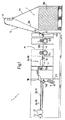
図1の符号1は、タバコフィルタを製造するための二重ストランド装置を全体として表している。装置1は、それぞれ連続するフィルタロッド3a、3bを形成するための2つのフォーマット形成区間2a、2bを備えるフォーマット形成部を含んでおり、ならびに、各々のフォーマット形成区間2a、2bについて、それぞれ1つのフィルタ材料供給部4a、4bを含んでいる。供給部4a、4bは、装置1の一部を形成し、供給部4a、4bの入口ステーション6と、フィルタ材料からなる2つのベイル8a、8bからなる備蓄領域7とのあいだを延びる搬送区間5から、フィルタ材料を受けとる。
Reference numeral 1 in FIG. 1 represents as a whole a double-strand device for producing a tobacco filter. The apparatus 1 includes a format forming section comprising two format forming sections 2a, 2b for forming
図1と図2に示すように、それぞれの粗糸9a、9bがベイル8a、8bから巻き出され、搬送区間5に沿って、入口ステーション6に配置された案内ロール構造10aによって搬送される。
As shown in FIGS. 1 and 2, the
搬送区間5は、粗糸9a、9bを案内するためにベイル8a、8bの上方に配置された二重案内装置11を含んでいる。さらに搬送区間5は、粗糸9a、9bを横方向へ引き伸ばして、案内装置10aに供給されるそれぞれ区域的に平坦なストライプ13a、13bにするために、搬送方向で見て入口ステーション6の案内構造10aのすぐ手前に配置された吸引装置12を含んでいる。案内装置10aの後、両方のストライプ13a、13bは供給部ないし供給区間4a、4bに沿って実質的に水平方向14に、案内ロール構造ないし制動ロール構造10aと2つの駆動ロール構造10b、10cとを含むプレス装置15を通るように搬送される。両方のストライプ13a、13bは、その後、それぞれの供給部4a、4bに沿って方向14へ、ストライプ13a、13bへ空気を吹き込んでその容積を増やす膨張装置16を通るように搬送される。その後、ストライプ13a、13bは前処理装置17を通るように搬送され、そこで化学物質、特にトリアセチンがストライプ13a、13bに添加され、それによりフィルタ材料に成形可能性および/またはアロマが与えられる。最後に両方のストライプ13a、13bはそれぞれの供給部4a、4bに沿って方向14へ、構造10b、10cと同様に構成され、供給部4a、4bないし供給区間4a、4bの出口領域を定義する駆動ロール構造10dを通るように搬送される。
The conveyance section 5 includes a
供給部4a、4bは、ロール構造10dの直後に配置された安定化ユニットないし転向装置18によって、フォーマット形成部のフォーマット形成区間2a、2bと連結されている。安定化ユニット18はストライプ13a、13bを供給部4a、4bから受けとり、ストライプ13a、13bを均等に集めてフィルタ材料からなる2本のストランドを形成し、このフィルタ材料ストランドをフォーマット形成区間2a、2bへと搬送する。両方のフォーマット形成区間2a、2bでは、各々のフィルタ材料ストランドが、事前にゴム引きステーション20でゴム引きされた紙テープ19a、19bの上に搬送され、引き続いてこの紙テープが、連続するフィルタロッド3a、3bを形成するために、フィルタ材料ストランドの回りへ横に巻きつけられる。
The
フォーマット形成区間2a、2bの出口部では、1つまたは複数の点検ステーション21がフィルタロッド3a、3bのさまざまな品質特性を点検する(たとえば密度、直径、外観・・・)。裁断ヘッド22がロッド3a、3bを横に切断して、それぞれ以後のフィルタ切片にする(図示せず)。
At the exit of the format forming sections 2a, 2b, one or
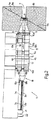
図3および図4に示すように、安定化ユニット18は、装置1のフレームに取り付けられ、両方のフィルタ材料ストランドの間隔を狭めるために集束する側方に相並んで配置された2つの安定化区間24a、24bを内部に保持する、ハウジング23を含んでいる。
As shown in FIGS. 3 and 4, the
各々の安定化区間24は、ストライプ13が供給部4から搬送されてくる入口漏斗25と、これに後置された出口漏斗26とを含んでおり、この出口漏斗を通ってフィルタトウストランドがフォーマット形成区間2へと搬送される。入口漏斗25と出口漏斗26はノズルをそれぞれ有しており、これらのノズルによって、ストランドを搬送するための駆動ガス流、特に空気流が生成される。したがって漏斗25、26は、それぞれ搬送ノズルとして機能する。各々の漏斗25は、搬送方向と平行に延びる、ないしは供給部4の領域でストライプ13の搬送平面に位置する、直線状の中央の対称軸27を有している。各々の出口漏斗26も、同じく、入口漏斗25からくるフィルタ材料ストランドの搬送方向に関して傾いて延びる、ならびにフォーマット形成区間2に沿ったフィルタ材料ストランドの搬送方向に関して傾いて延びる、直線状の中央の対称軸28を有している。それぞれの入口漏斗25と出口漏斗26のあいだには管状の転向部が配置されており、特に、入口漏斗25からくるフィルタ材料ストランドの搬送方向を転向させるために湾曲した区域を有する湾曲円弧部29が配置されている。各々の湾曲円弧部29は、入口漏斗25の排出部と直接連結されているのが好ましい。
Each stabilizing
フィルタ材料ストランドにおけるフィルタ材料の均質性をさらに改善するために、各々の漏斗25、26へ空気が吹き込まれる。具体的には、各々の漏斗25、26は、狭く先細になっていく入口領域(すなわち次第に減少していく流動通路直径)と、円筒状の中間区域(すなわち一定の流動通路直径)とを備える管状体30を含んでいる。さらに各々の漏斗25、26は、管状体30に後置された、若干拡張している別の管状体31(すなわち次第に増加していく流動通路直径)を含んでいる。
Air is blown into each
管状体30は別の管状体31にねじ込まれており、それにより、管状体30の外面と別の管状体31の内面とのあいだには管状の空気流動通路32が仕切られており、この空気流動通路に、管状体30の内面を円筒状の中間区域で貫通する複数の吹付け開口部33が開口している。供給通路34が別の管状体31に形成されており、この供給通路を通って作動時に圧縮空気が管状通路32へ、およびそこから吹付け開口部33を通って管状体30の流動通路へと吹き込まれる。
The
入口漏斗25の吹付け開口部33は中央の対称軸27に関して、空気流に軸方向成分が印加されるような、すなわち中央の対称軸27と平行な成分が印加されるような方向を向いている。
The blowing
一変形例では、入口漏斗25の吹付け開口部33は中央の対称軸27に関して、軸方向成分だけでなく半径方向成分(すなわち中央の対称軸27に対して垂直方向)も、空気に印加されるような方向を向いている。この場合、入口漏斗25を通過するようにフィルタ材料を押圧する役目をする軸方向の空気流成分の方が優勢であり、それに対して半径方向の空気流成分は、空気流に渦形成をさせる役目をする。
In one variant, the blowing
出口漏斗26の吹付け開口部33は中央の対称軸28に関して、主として軸方向成分(すなわち中央の対称軸28と平行)が空気流に印加されるような方向を向いており、それにより、フィルタ材料に作用する推進力が最大化される。
The
安定化ユニット18の組立と調節の際には、管状体13が別の管状体31へねじ込まれ、ないしは外されることによって、各々の管状通路32の空気流領域を調製することができ、それにより、吹付け開口部33を通る空気速度と空気流が調整される。
During assembly and adjustment of the
さらに付言しておくと、フィルタストランド材料は各々の入口漏斗25と出口漏斗26のあいだでは自由空間35を通って搬送され、このときフィルタストランド材料は自由に、すなわち案内部材なしに移動する。
It is further noted that the filter strand material is transported through the free space 35 between each
図1〜図4に示す実施例には、各々の漏斗25は目打ちのある管状の膨張部によって、対応する漏斗26と連結されていた変形例が含まれる。
The embodiment shown in FIGS. 1 to 4 includes a modification in which each funnel 25 is connected to a
フィルタストランド材料が自由に動いて通過していく自由空間35は、各入口漏斗25の吹付け開口部33を通って吹き込まれる圧縮空気の膨張を可能にし、それによって望ましくない背圧現象が回避される。さらにそれにより、前処理装置17で添加された余剰の化学物質を、フィルタストランド材料が放出することが可能になる。フィルタストランド材料から放出される化学物質を回収して排出するために、ハウジング23は下方に向かって傾くように配置されるとともに、最も低い点のところに、受水槽へと通じる受水通路を有している。フィルタストランド材料から放出された化学物質がハウジング23から外へ逃げて他の装置1を汚染するのを回避するために、ハウジング23は実質的に密閉されており、ハウジング23の中央領域に配置されていて直接的な噴霧に対して遮蔽された排出開口部だけを有している。
The free space 35 through which the filter strand material moves freely allows for the expansion of compressed air blown through the blowing
吹付け開口部33を通って各々の出口漏斗26へ吹き込まれる圧縮空気の自由な膨張を可能にするために(および、それによって望ましくない背圧現象を回避するために)、各々の出口漏斗26は、複数の開口部38を有し、出口漏斗26のすぐ後に配置された、若干テーパ状になった目打ちのある管状体37を備えている。目打ちされた各々の管状体37にある貫通孔38は、下方に向かう空気流すなわちフォーマット形成区間2に向かう空気流を回避するために、目打ちされた管状体37の上面にだけ配置されているのが好ましい。
In order to allow free expansion of the compressed air blown into each
実施例には、安定化ユニット18の各々の安定化区間24は、入口漏斗25と出口漏斗26のあいだに配置され、漏斗25、26と同一に構成された、1つ、2つ、またはそれ以上の中間漏斗を備えたもの(図示されず)が含まれる。
In an embodiment, each
実施例には、上に説明した装置1が単一ストランド装置として構成されており、すなわち、連続するフィルタロッド3を形成するための1つのフォーマット形成区間2を備えるフォーマット形成部と、1つのフィルタ材料供給部4とを備えたもの(図示されず)が含まれる。この場合、安定化ユニットないし転向装置18は、上に説明した入口漏斗および出口漏斗25、26を備える1つの安定化区間24を含んでいる。これに類似した仕方で、上に説明した装置1は三重ストランド装置または4重ストランド装置として構成されていてもよく、すなわち、3つまたは4つの連続するフィルタロッド3を形成するための3つまたは4つのフォーマット形成区間2を備えるフォーマット形成部と、3つまたは4つのフィルタ材料供給部4とを含んでいてよい。この場合、安定化ユニットないし転向装置18は、それぞれ上に説明した入口漏斗および出口漏斗25、26を備える3つまたは4つの安定化区間24を有している。
In the embodiment, the device 1 described above is configured as a single-strand device, i.e. a format-forming part with one format-forming section 2 for forming a
上に説明した安定化ユニットないし転向装置18で製作可能なフィルタ材料は非常に優れた均質性を有しており、少なくとも均質性の観点からは、現在市場で入手できる安定化ユニットで製作されるフィルタ材料を凌駕している。
The filter material that can be produced with the stabilization unit or turning
駆動ロール構造10b、10c、10dは、供給部4a、4bに沿ってサイズと構造の点で区別されているが、機能的には同一である。したがって以下の説明は、これらの駆動ロール構造10b、10c、10dのうちの1つだけを対象として行い、これを便宜上符号10で表す。各々の駆動ロール構造10は各々の供給部4について、モータにより他のロールのモータとは関わりなく回転する駆動ロールと、駆動ロールに当接してこれと協働する、自由回転をするロールとを含んでいる。各々の駆動ロール構造10の両方の駆動ロールの両方のモータは、供給部4の同一の側で装置フレームに配置されていてよい。各々の駆動ロール構造10において、一方の駆動ロールのモータが装置1のフレームに配置され、他方の駆動ロールのモータが駆動ロールの横に配置された変形例を採用してもよい。
The
次に、安定化ユニット18とも呼ばれる転向装置について詳しく説明する。
Next, the turning device, also called the
図3および図4に示すように、転向装置は基本的に、転向装置を通って移動するフィルタトウストランド13の転向が空気圧式に行われるように互いに協働する、転向器具50と搬送装置40とを有している。
As shown in FIGS. 3 and 4, the turning device is basically a
転向装置を工業的に具体化するにはさまざまな選択肢がある。たとえば、図3および図4に示すように、空気圧式に作動する搬送ノズル25、26と接続された湾曲円弧部29を利用することが可能である。図3および図4に示す例では、転向装置18の入口側にある搬送ノズル25a、25bだけが、それぞれ湾曲円弧部29a、29bを備えている。
There are various options for industrializing the turning device. For example, as shown in FIGS. 3 and 4, it is possible to use a
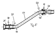
転向装置の出口側にある搬送ノズル26a、26bだけに、それぞれ湾曲円弧部(図示せず)を設けることも可能である。さらに別のオプションの要諦は、転向装置の出口側の搬送ノズル26と入口側の搬送ノズル25の両方に、湾曲円弧部29をそれぞれ設けることにある(図5〜図7)。
It is also possible to provide curved arc portions (not shown) only on the
一般に、湾曲円弧部を図3および図4に示すように搬送方向で見て付属の搬送ノズルの後に配置することが可能であり、このことはストランドが空気圧式に、すなわち圧縮空気の供給によって、湾曲円弧部29を通るように押圧されることを意味している。図5〜図7に転向装置の出口側にある搬送ノズル26について示すように、湾曲円弧部29が搬送方向で見て各搬送ノズルの上方に配置されていると、ストランドは湾曲円弧部29を通るように吸引される。
In general, it is possible to place the curved arc in the conveying direction as shown in FIGS. 3 and 4 after the attached conveying nozzle, which means that the strand is pneumatically, ie by supplying compressed air. It means that it is pressed so as to pass through the
さらに、湾曲円弧部29を搬送方向で見て各ノズルの上方および/または下方に配置することが可能であり、この場合、湾曲円弧部を搬送方向で見てノズルの下方に配置し、それによってストランドを空気圧式に湾曲円弧部を通るように押圧する選択肢の方が、フィルタ材料の引張強さや、そのばらつきの観点から、より良い結果につながる。
Furthermore, it is possible to arrange the
図4および同様に図5〜図7にも見られるように、転向器具50は、少なくとも1つの水平方向成分を含んでいる方向へフィルタトウストランドの転向を引き起すために適合化されている。図3に示す例では、転向装置全体が水平面に対して傾いて配置されているので、水平方向成分と垂直方向成分を両方とも含んでいる転向が行われる。
As seen in FIG. 4 and also in FIGS. 5-7, the turning
ここで転向とは一般に、搬送方向が少なくとも1回だけ変わることを意味している。 Here, turning generally means that the transport direction changes at least once.
転向器具50を工業的に具体化するために、湾曲円弧部29を別の手段で置き換えることができ、たとえば開いた構造を備えるコンポーネントで置き換えることができ、特に、空気圧式の搬送装置40に付属する湾曲した阻流板で置き換えることができる。湾曲した阻流板は、フィルタトウストランド13の所望のオフセットを実現すると同時に、フィルタトウストランドを連続的に転向させるために利用することができる。
In order to industrially embody the
一般に、連続的かつ空気圧式に駆動されるフィルタトウストランドの転向を可能にするコンポーネントを、転向器具50を工業的に具体化するために使用することができる。このことは、フィルタトウストランドの案内経路を少なくとも区域的に仕切ると同時に搬送方向を変える、連続的に湾曲した少なくとも1つの壁部を転向器具50が有しているのがよいことを意味している。一般に、転向器具50は、入口漏斗または入口搬送ノズルと出口漏斗または出口搬送ノズルとのあいだに配置された転向部分を含んでいる。転向部分は管状に構成されていてよく、入口漏斗または入口搬送ノズルからくるフィルタ材料ストランドないし粗糸の搬送方向を転向させるための湾曲した区域を含んでいる。
In general, components that enable the turning of continuously and pneumatically driven filter tow strands can be used to industrially implement the
転向装置を二重ストランド装置で使用するときには、両方のストランドが接近しながら供給されるように、すなわち集束するように(図4)、搬送方向を変えるのが好ましい。そしてこれらのストランドを、装置のフォーマット形成部の導入システムへ供給することができる。別のケースでは、たとえば互いに間隔をおいて配置された2つの別々のフォーマット形成部が使用されるときなどには、上記と異なる方向へストランドを転向させるのが有意義な場合がある。 When the turning device is used in a double strand device, it is preferable to change the transport direction so that both strands are fed in close proximity, ie converge (FIG. 4). These strands can then be supplied to the introduction system of the format forming unit of the apparatus. In other cases, it may be meaningful to redirect the strands in a different direction from the above, for example when two separate format forming portions are used that are spaced apart from each other.
湾曲円弧部29がそれぞれの搬送ノズル25、26と取外し可能に連結されていると、本装置がいっそうフレキシブルに構成される。そうすれば、さまざまなプロセス条件に合わせて本装置を適合化することができるからである。これに加えて、湾曲円弧部29が旋回可能ないし回転可能に配置されていてよく、それにより、ストランドがそれぞれの湾曲円弧部29から出ていくときの方向を変えることができる。本装置の入口側の湾曲円弧部29と出口側の湾曲円弧部29を、それぞれの湾曲円弧部29を相応に旋回させることによって、簡単にアライメントすることができる。
When the
図4に見られるように、本装置の入口側にある各々の湾曲円弧部29a、29bは、湾曲円弧部29a、29bの自由端の中央の対称軸が、本装置の出口側にある、離れて配置された搬送ノズル26a、26bの中央の対称軸と入口平面で交差するような方向を向いている。本装置の出口側にある搬送ノズル26a、26bに対するこのような湾曲円弧部29a、29bのアライメントは、それぞれの湾曲円弧部29a、29bから搬送ノズル26a、26bへのストランド13の均等な移行をもたらす。
As can be seen in FIG. 4, each
図3および図4に示す実施例は、湾曲円弧部29a、29bと出口搬送ノズル26a、26bとのあいだに自由空間35を有している転向装置に関わるものである。別案として、本装置の入口側にある湾曲円弧部29と、本装置の出口側にある湾曲円弧部29’とをつなぐ管区域51、特に直線状の管区域51を設けることも可能である。この系統の所望のオフセットを実現するために、両方の湾曲円弧部29、29’は反対方向に湾曲しており、それぞれの搬送ノズル25、26の中央の対称軸と同軸である湾曲円弧部29、29’の中央の対称軸は、それぞれ平行に延びている。さらに、それぞれ付属の搬送ノズル25、26から離れて配置されているそれぞれの湾曲円弧部29、29’の各端部は一直線上に並んでおり、それにより、管区域51を両方の湾曲円弧部29、29’のあいだへ嵌め合わせることができる。
The embodiment shown in FIGS. 3 and 4 relates to a turning device having a free space 35 between the
管区域51は、管系統の長さを伸ばすためのきわめて有効な手段である。それにより、システムで実現可能なフィルタ材料の渦形成とブルーミング現象(blooming effect)が強化される。管区域51は、必ずしも直線状に延びている必要はない。少なくとも区域的に湾曲円弧部を有する、ないし一般的に言えば湾曲している、管区域を使用することも可能である。
The
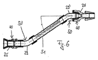
図6に示すように、管区域51は、本装置の入口側にある搬送ノズル25によって供給された圧縮空気が外に出られるようにするために、目打ちされていてよい。
As shown in FIG. 6, the
図面には示さない、本発明のさらに別の好ましい実施形態では、たとえば活性炭、軟化剤、またはその他の物質のような添加剤をフィルタトウストランドへ供給することを可能にする供給装置が管区域に付属している。さらにこの供給装置は、水をストランドへ供給し、それによって硬化時間に影響を与えるために利用することができる。管区域51の1つの格別な利点は、システムの長さが伸びるという点にある。それにより、供給される添加剤および/または供給される水が、管区域の長さ全体にわたって均等にフィルタトウストランドで分散されることが可能となる。このようにして、このような転向装置を含んでいる装置で製造されるフィルタロッドの品質を、有意に改善することができる。
In yet another preferred embodiment of the present invention, not shown in the drawings, a supply device is provided in the tube section that allows additives such as activated carbon, softeners, or other materials to be supplied to the filter tow strand. Comes with. Furthermore, this supply device can be used to supply water to the strands, thereby affecting the curing time. One particular advantage of the
転向装置の寸法の観点からは、転向器具50の水平方向のオフセットが少なくとも5cmであるのが好ましい。1つの好ましい範囲は5〜50cm、特に10〜40cm、特に15〜30cmである。本装置の長手方向の全長は、少なくとも200mmであるのが望ましい。このことは、本装置の入口側と出口側とのあいだの軸方向間隔が少なくとも200mmであることを意味している。好ましい範囲は200〜1000mm、特に500〜900mm、特に600〜800mmである。
From the viewpoint of the dimensions of the turning device, the horizontal offset of the
各々の湾曲円弧部の湾曲角は少なくとも10°である。このとき湾曲角とは、湾曲円弧部の両方の中央の対称軸にはさまれた鋭角である。図7の湾曲角は符号aが付されている。好ましい範囲は10°〜80°、特に20°〜60°、特に30°〜50°である。 The bending angle of each curved arc portion is at least 10 °. At this time, the bending angle is an acute angle sandwiched between the central symmetry axes of both of the curved arc portions. The bending angle in FIG. A preferred range is 10 ° to 80 °, in particular 20 ° to 60 °, in particular 30 ° to 50 °.
以上に説明した転向装置は、単一ストランド装置用としても二重ストランド装置用としても使用することができ、単一ストランド装置用として意図される実施例は図5および図6に、また二重ストランド装置用として意図される実施例は図1〜図4および図7に、それぞれ示されている。 The turning device described above can be used for both single-strand and double-strand devices, and examples intended for single-strand devices are shown in FIGS. Examples intended for the strand device are shown in FIGS. 1-4 and 7 respectively.
図5〜図7に示す管系統は、図1〜図4に示す転向器具50について意図されているように、ハウジング23の中に配置されていてもよい。
The tubing shown in FIGS. 5-7 may be disposed in the
要約すると、本発明による装置は、系統内での渦形成の改善およびこれに伴うフィルタ材料の均質性向上につながる、組み合わせ型の転向および空気圧式の搬送に基づいて、引張強さならびに引張強さのばらつきを改善する。 In summary, the device according to the invention is based on a combination of turning and pneumatic conveying, which leads to improved vortex formation in the system and the resulting increased homogeneity of the filter material. Improve the variation of
さらに、以上に説明した転向装置は、加工速度が高いときに発生する脈動の減衰を可能にする。脈動の減衰は、特に、本装置の入口側と出口側に付属する2つの湾曲円弧部のあいだでの管区域の使用との関連で、搬送経路の拡張された長さに基づいて行われる。このようにして、ブルーミング現象も改善することができる。 Furthermore, the turning device described above enables attenuation of pulsation that occurs when the machining speed is high. The pulsation attenuation is based on the extended length of the transport path, particularly in the context of the use of the tube section between the two curved arcs attached to the inlet and outlet sides of the device. In this way, the blooming phenomenon can also be improved.
1 装置
2a、2b フォーマット形成部
3a、3b フィルタロッド
4a、4b 供給部
5 搬送区間
6 入口ステーション
7 備蓄領域
8a、8b ベイル
9a、9b 粗糸
10a 案内ロール構造
10b、10c 駆動ロール構造
10d ロール構造
11 二重案内装置
12 吸引装置
13a、13b ストランド
14 水平方向
15 プレス装置
16 膨張装置
17 前処理装置
18 安定化構造ないし転向装置
19a、19b ゴム引きされた紙からなるテープ
20 ゴム引きステーション
21 点検ステーション
22 裁断ヘッド
23 ハウジング
24a、24b 安定化区間
25、26 搬送ノズル
27、28 対称軸
29 湾曲円弧部
30 管状体
31 別の管状体
32 空気通路
33 吹付け開口部
34 供給通路
35 自由空間
36 吐出開口部
37 目打ちされた管状体
40 搬送装置
50 転向器具
51 管区域
DESCRIPTION OF SYMBOLS 1 Apparatus 2a, 2b
Claims (51)
Applications Claiming Priority (2)
| Application Number | Priority Date | Filing Date | Title |
|---|---|---|---|
| DE200610001643 DE102006001643A1 (en) | 2006-01-12 | 2006-01-12 | Deflection device for conveying and deflection of filter tow strand, has passage and returning device, which cooperates with transport unit for pneumatically driven deflection of filter tow strand |
| PCT/EP2006/011042 WO2007087848A2 (en) | 2006-01-12 | 2006-11-15 | Deflecting device for a continuous filter tow, method for conveying and deflecting at least one continuous filter tow, and device for the production of cigarette filters |
Publications (2)
| Publication Number | Publication Date |
|---|---|
| JP2009523015A true JP2009523015A (en) | 2009-06-18 |
| JP2009523015A5 JP2009523015A5 (en) | 2010-01-07 |
Family
ID=37461573
Family Applications (1)
| Application Number | Title | Priority Date | Filing Date |
|---|---|---|---|
| JP2008549773A Pending JP2009523015A (en) | 2006-01-12 | 2006-11-15 | Turning device, device with the turning device, and method for conveying and turning at least one filter tow strand |
Country Status (5)
| Country | Link |
|---|---|
| EP (1) | EP1978833B1 (en) |
| JP (1) | JP2009523015A (en) |
| CN (1) | CN101394760B (en) |
| DE (2) | DE102006001643A1 (en) |
| WO (1) | WO2007087848A2 (en) |
Cited By (1)
| Publication number | Priority date | Publication date | Assignee | Title |
|---|---|---|---|---|
| JP2011036249A (en) * | 2009-08-18 | 2011-02-24 | G D Spa | Method and mechanical equipment for simultaneously producing at least two tobacco filter rods |
Families Citing this family (11)
| Publication number | Priority date | Publication date | Assignee | Title |
|---|---|---|---|---|
| DE102007057396A1 (en) | 2007-11-27 | 2009-05-28 | Hauni Maschinenbau Ag | Device for processing at least two filter tows |
| DE102008003368A1 (en) * | 2008-01-08 | 2009-07-09 | Hauni Maschinenbau Aktiengesellschaft | Device for transporting a filter tow |
| DE102008016827A1 (en) * | 2008-04-01 | 2009-10-08 | Hauni Maschinenbau Ag | Device for transporting a filter tow |
| DE102008024553A1 (en) | 2008-05-21 | 2009-12-03 | Hauni Maschinenbau Aktiengesellschaft | Device for introducing additives into a strand provided for the production of a smoking article and already round-shaped |
| DE102008057457A1 (en) * | 2008-11-14 | 2010-05-20 | Hauni Maschinenbau Aktiengesellschaft | Device for transporting a filter tow strip |
| DE102009017963A1 (en) | 2009-04-21 | 2010-10-28 | Hauni Maschinenbau Ag | Capsule monitoring and capsule position control in filters of the tobacco processing industry |
| DE102009022790A1 (en) | 2009-05-27 | 2010-12-02 | Hauni Maschinenbau Aktiengesellschaft | Apparatus for processing filter bowl line in tobacco processing industry, has filter bowl guide path, along which filter bowl line is guided in transport direction |
| IT1408375B1 (en) * | 2010-10-20 | 2014-06-20 | Gd Spa | UNIT AND METHOD OF FEEDING ELEMENTS OF ADDITIVES OF FIBER MATERIAL IN A MACHINE FOR THE PRODUCTION OF SMOKE ITEMS |
| ITBO20100637A1 (en) * | 2010-10-22 | 2012-04-23 | Gd Spa | MACHINE FOR THE PRODUCTION OF FILTERS FOR CIGARETTES. |
| ITBO20110206A1 (en) | 2011-04-18 | 2012-10-19 | Gd Spa | COMPACT GROUP FOR A MACHINE FOR THE PRODUCTION OF FILTERS FOR CIGARETTES. |
| ITBO20130314A1 (en) | 2013-06-21 | 2014-12-22 | Gd Spa | MACHINE FOR THE PRODUCTION OF FILTERS FOR CIGARETTES |
Citations (3)
| Publication number | Priority date | Publication date | Assignee | Title |
|---|---|---|---|---|
| JPH05211860A (en) * | 1991-12-09 | 1993-08-24 | Mitsubishi Rayon Co Ltd | Air jet |
| WO2005009151A1 (en) * | 2003-07-25 | 2005-02-03 | Mitsubishi Rayon Co., Ltd. | Manufacturing apparatus for plug of cigarttte filter and manufacturing method for the filter |
| WO2005058079A1 (en) * | 2003-11-25 | 2005-06-30 | Hauni Maschinenbau Aktiengesellschaft | Device for processing filter tow material, and device for the production of filters |
Family Cites Families (10)
| Publication number | Priority date | Publication date | Assignee | Title |
|---|---|---|---|---|
| US4511420A (en) * | 1980-12-16 | 1985-04-16 | Molins, Ltd. | Continuous rod manufacture |
| GB2089190B (en) * | 1980-12-16 | 1985-05-30 | Molins Ltd | Quality control in continuous rod manufacture |
| US4522616A (en) * | 1982-03-10 | 1985-06-11 | Celanese Corporation | Method and apparatus for forming cigarette filter rods |
| US4541825A (en) * | 1982-12-27 | 1985-09-17 | Celanese Corporation | Low air pressure method and apparatus for forming filter rods |
| IT1185472B (en) | 1984-11-10 | 1987-11-12 | Hauni Werke Koerber & Co Kg | PROCEDURE AND DEVICE FOR PRODUCING STICKS-FILTER |
| DE3640883A1 (en) | 1986-11-29 | 1988-06-09 | Rhodia Ag | METHOD AND DEVICES FOR MANUFACTURING TOBACCO Fume Filter Rods |
| DE4300841A1 (en) * | 1992-01-16 | 1993-07-22 | Molins Plc | |
| US5331976A (en) * | 1992-10-21 | 1994-07-26 | Hoechst Celanese Corporation | Transport jet adapter |
| DE10200320A1 (en) * | 2002-01-07 | 2003-07-17 | Hauni Maschinenbau Ag | Method and device for producing a fiber strand of the tobacco processing industry |
| CN2642061Y (en) * | 2003-04-16 | 2004-09-22 | 云南烟草科学研究院 | Device for feeding liquid and linear materials in acetate silk |
-
2006
- 2006-01-12 DE DE200610001643 patent/DE102006001643A1/en not_active Ceased
- 2006-11-15 CN CN200680053609.9A patent/CN101394760B/en not_active Expired - Fee Related
- 2006-11-15 DE DE502006008784T patent/DE502006008784D1/en active Active
- 2006-11-15 EP EP06818621A patent/EP1978833B1/en active Active
- 2006-11-15 WO PCT/EP2006/011042 patent/WO2007087848A2/en active Application Filing
- 2006-11-15 JP JP2008549773A patent/JP2009523015A/en active Pending
Patent Citations (3)
| Publication number | Priority date | Publication date | Assignee | Title |
|---|---|---|---|---|
| JPH05211860A (en) * | 1991-12-09 | 1993-08-24 | Mitsubishi Rayon Co Ltd | Air jet |
| WO2005009151A1 (en) * | 2003-07-25 | 2005-02-03 | Mitsubishi Rayon Co., Ltd. | Manufacturing apparatus for plug of cigarttte filter and manufacturing method for the filter |
| WO2005058079A1 (en) * | 2003-11-25 | 2005-06-30 | Hauni Maschinenbau Aktiengesellschaft | Device for processing filter tow material, and device for the production of filters |
Cited By (1)
| Publication number | Priority date | Publication date | Assignee | Title |
|---|---|---|---|---|
| JP2011036249A (en) * | 2009-08-18 | 2011-02-24 | G D Spa | Method and mechanical equipment for simultaneously producing at least two tobacco filter rods |
Also Published As
| Publication number | Publication date |
|---|---|
| CN101394760B (en) | 2011-09-28 |
| CN101394760A (en) | 2009-03-25 |
| WO2007087848A3 (en) | 2007-10-25 |
| WO2007087848A2 (en) | 2007-08-09 |
| DE502006008784D1 (en) | 2011-03-03 |
| EP1978833B1 (en) | 2011-01-19 |
| EP1978833A2 (en) | 2008-10-15 |
| DE102006001643A1 (en) | 2007-07-26 |
Similar Documents
| Publication | Publication Date | Title |
|---|---|---|
| JP2009523015A (en) | Turning device, device with the turning device, and method for conveying and turning at least one filter tow strand | |
| JP4584371B2 (en) | Method and apparatus for processing filter tow strips | |
| US10039316B2 (en) | Cigarette filter manufacturing apparatus and cigarette filter manufacturing method | |
| US5331976A (en) | Transport jet adapter | |
| WO2011114440A1 (en) | Filter manufacturing machine | |
| CA2480886A1 (en) | Method and apparatus for making cigarette filters with a centrally located flavored element | |
| US20150164133A1 (en) | Filter for a Smoking Article | |
| JP2009523015A5 (en) | ||
| KR102355964B1 (en) | Methods and equipment for forming tubes of fiber material | |
| JP2018174920A (en) | Apparatus for transferring rod-like article of tobacco processing industry | |
| EP2910133B1 (en) | Filter rod manufacturing machine and filter rod manufacturing method | |
| JP2009278973A (en) | Device for inserting additives into rounded strand for manufacture of tobacco products | |
| JP2012239437A (en) | Tow transport jet | |
| GB2145918A (en) | Producing filler material, particularly for cigarette filters | |
| US6334243B1 (en) | Method of and apparatus for manipulating tows of filter material for tobacco smoke | |
| US20220160024A1 (en) | Methods and Equipment for Gathering Fibres | |
| KR101853778B1 (en) | Tow cutter | |
| CN101480275B (en) | Device for transporting a filter tow | |
| JP2009541172A (en) | Fiber conveying apparatus and method | |
| JP2010273677A (en) | Preparation of filter material strap of tobacco-processing industry | |
| EP2818061A1 (en) | Cigarette filter manufacturing machine | |
| CN111904021A (en) | Device for transferring rod-shaped articles of the tobacco processing industry | |
| TH47613A (en) | Equipment And the process for producing filter strings being performed with filler conditioning. |
Legal Events
| Date | Code | Title | Description |
|---|---|---|---|
| A521 | Request for written amendment filed |
Free format text: JAPANESE INTERMEDIATE CODE: A523 Effective date: 20090424 |
|
| A521 | Request for written amendment filed |
Free format text: JAPANESE INTERMEDIATE CODE: A523 Effective date: 20091110 |
|
| A621 | Written request for application examination |
Free format text: JAPANESE INTERMEDIATE CODE: A621 Effective date: 20091110 |
|
| RD03 | Notification of appointment of power of attorney |
Free format text: JAPANESE INTERMEDIATE CODE: A7423 Effective date: 20100818 |
|
| A131 | Notification of reasons for refusal |
Free format text: JAPANESE INTERMEDIATE CODE: A131 Effective date: 20120214 |
|
| A02 | Decision of refusal |
Free format text: JAPANESE INTERMEDIATE CODE: A02 Effective date: 20120710 |