EP2910133B1 - Filter rod manufacturing machine and filter rod manufacturing method - Google Patents
Filter rod manufacturing machine and filter rod manufacturing method Download PDFInfo
- Publication number
- EP2910133B1 EP2910133B1 EP12890930.6A EP12890930A EP2910133B1 EP 2910133 B1 EP2910133 B1 EP 2910133B1 EP 12890930 A EP12890930 A EP 12890930A EP 2910133 B1 EP2910133 B1 EP 2910133B1
- Authority
- EP
- European Patent Office
- Prior art keywords
- filter
- thread
- tow
- liquid
- rod
- Prior art date
- Legal status (The legal status is an assumption and is not a legal conclusion. Google has not performed a legal analysis and makes no representation as to the accuracy of the status listed.)
- Active
Links
Images


Classifications
-
- A—HUMAN NECESSITIES
- A24—TOBACCO; CIGARS; CIGARETTES; SIMULATED SMOKING DEVICES; SMOKERS' REQUISITES
- A24D—CIGARS; CIGARETTES; TOBACCO SMOKE FILTERS; MOUTHPIECES FOR CIGARS OR CIGARETTES; MANUFACTURE OF TOBACCO SMOKE FILTERS OR MOUTHPIECES
- A24D3/00—Tobacco smoke filters, e.g. filter-tips, filtering inserts; Filters specially adapted for simulated smoking devices; Mouthpieces for cigars or cigarettes
- A24D3/02—Manufacture of tobacco smoke filters
- A24D3/0204—Preliminary operations before the filter rod forming process, e.g. crimping, blooming
- A24D3/0212—Applying additives to filter materials
Definitions
- the present invention relates to a filter rod manufacturing machine and a filter rod manufacturing method for manufacturing a filter rod several times longer than a filter prior to manufacturing of a filter cigarette including a thread into which an additive liquid is impregnated inside the filter.
- a manufacturing machine of this type includes a wrapping section for wrapping a filter tow with a wrapping material into a rod shape to form a tow rod, a cutting unit so disposed downstream of this wrapping section as to cut the tow rod into filter rods, and a thread feed-out unit for feeding an additive-impregnated thread into the filter tow in a process of conveying the filter tow toward the wrapping section (see FIG. 3 of Patent Document 1, for example).
- each filter rod includes the additive-impregnated thread in its filter tow.
- the thread feed-out unit of Patent Document 1 includes a feed-out path of a thread member extending from a feed reel of the thread toward the wrapping section and a liquid tank disposed in this feed path, an additive liquid is reserved in this liquid tank, and a flavor is dissolved in this additive liquid.
- the thread member is conveyed through the additive liquid in the liquid tank before being fed into the filter tow, thereby impregnating the additive liquid into the thread member to obtain the additive-impregnated thread.
- the above described thread feed-out unit of Patent Document 1 further includes a thread guide and a thread nozzle in the thread feed-out path downstream of the liquid tank, and the thread guide and the thread nozzle enable the additive-impregnated thread to be accurately fed into the filter tow.
- Patent Document 2 describes a filter rod manufacturing machine according to the preamble of claim 1 and a filter rod manufacturing method according to the preamble of claim 6.
- An object of the present invention is to provide a filter rod manufacturing machine and a filter rod manufacturing method capable of effectively reducing variation in impregnated amount in terms of the impregnated amount of an additive liquid contained in an additive-impregnated thread in each filter rod.
- the thread member is fed into the filter tow located more downstream than the merging position between the filter tow and the wrapping material, and the additive liquid is discharged toward this thread member at the same time.
- the additive-impregnated thread made by impregnating the additive liquid into the thread member is not formed outside the filter tow, but inside the filter during conveyance of the filter tow in a web shape; a wrapping section for respectively receiving the converged filter tow and a wrapping material at a merging position defined to be downstream of the tow converging section if viewed in a conveyance direction of the filter tow so as to wrap the filter tow with the wrapping material into a tow rod; a thread feed-out nozzle for guiding a thread member toward the wrapping section, the thread feed-out nozzle including a thread feed-out end located more downstream than the merging position, the thread feed-out nozzle feeding the thread member from the thread feed-out end into the filter tow, thereby forming the tow rod including the thread member there
- the thread member is fed into the filter tow located more downstream than the merging position between the filter tow and the wrapping material, and the additive liquid is discharged toward this thread member at the same time.
- the additive-impregnated thread made by impregnating the additive liquid into the thread member is not formed outside the filter tow, but inside the filter tow; thus it is possible to eliminate the aforementioned thread guider and thread nozzle for leading the additive-impregnated thread into the filter tow.
- the additive-impregnated thread does not slidingly come into direct contact with the thread guide and the thread nozzle; therefore, it is prevented that the thread guide and the thread nozzle squeeze the additive liquid from the additive-impregnated thread, and then the squeezed additive liquid adheres to the thread guide and the thread nozzle. Accordingly, variation in impregnated amount of the additive liquid is suppressed in terms of the impregnated amount of the additive liquid contained in the additive-impregnated thread per filter rod.
- the wrapping section includes the tong so located downstream of the merging position as to squeeze the filter tow into a rod shape, and in this case, the thread feed-out end and the liquid discharge outlet are preferably disposed inside the tong.
- the thread feed-out end and the liquid discharge outlet are disposed inside the tong as described above, the thread feed-out end and the liquid discharge outlet are surrounded by the filter tow in a process of forming the filter tow into a rod shape. Hence, even if part of the additive liquid discharged from the liquid discharge outlet is not impregnated into the thread member, the part of the additive liquid is prevented from adhering to the adjacent filter tow, and thus the tong and the wrapping material are prevented from being unclean with this additive liquid.
- the liquid discharge outlet is preferably disposed at the front end of the liquid supply nozzle. This configuration minimizes the insertion length of the liquid supply nozzle into the tong.
- the liquid supply nozzle may extend immediately under the thread feed-out nozzle, and the liquid discharge outlet may upwardly open.
- the additive liquid upwardly discharged from the liquid discharge outlet is so applied to the lower surface of the thread member as to be impregnated into the thread member. With the liquid discharge outlet upwardly opening, the additive liquid is prevented from oozing out from the liquid discharge outlet because of gravity even if the additive liquid is stopped to be discharged from the liquid discharge outlet.
- liquid supply nozzle and the thread feed-out nozzle are integrally supported by a common holder plate.
- the present invention also provides a filter rod manufacturing method carried out by the aforementioned manufacturing machine.
- the filter rod manufacturing machine and the filter rod manufacturing method of the present invention form the additive-impregnated thread in the filter tow; therefore, it is possible to effectively suppress variation in impregnated amount of the additive liquid in terms of the impregnated amount of the additive liquid contained in the additive-impregnated liquid per filter rod.
- a filter cigarette FC includes a cigarette C, and a filter F connected to a base end of the cigarette C by wrapping them with a tipping paper TP.
- the filter F includes a flavor-impregnated thread FT thereinside, and the flavor-impregnated thread FT contains a flavor.
- the filter F is produced by cutting a filter rod FR shown in FIG. 2 .
- the filter rod FR includes a filter tow T formed of a bundle of acetate fibers, a wrapping material for wrapping the filter tow T into a rod shape, that is, a wrapping paper WP, and the flavor-impregnated thread FT disposed at a center of the filter tow T.
- FIG. 3 schematically shows a structural outline of a manufacturing machine of the filter rod FR, and a manufacturing method of the filter rod FR carried out by this manufacturing machine will be apparent from the following description according to the manufacturing machine.
- the manufacturing machine includes a tow bale formed of acetate fibers, that is, the filter tow T in a web shape, and the filter tow T forms a pile 12 on a wagon 10.
- a conveyance path 16 of the filter tow T extends from the pile 12 toward a tow converging section 14, and in this conveyance path 16, there are sequentially disposed a ring guide 18, a first banding jet 20, a second banding jet 22, pretension rolls 24, blooming rolls 26, a third banding jet 28, an plasticizer applying unit 30, and conveyance rolls 32 in the order from the pile 12 of the filter tow T.
- the first to third banding jets 20, 22, 28 respectively inject compressed air to the filter tow T, and this injection of the compressed air opens crimped acetate fibers, thus opening the filter tow T.
- the pretension rolls 24 apply a predetermined tension to the filter tow T, and the blooming rolls 26 stretch out the filter tow T incorporation with the pretension rolls 24 therebetween.
- the applying unit 30 evenly applies liquid triacetin as a plasticizer to the filter tow T. Subsequently, the filter tow T is conveyed from the conveyance rolls 32 to the tow converging section 14.
- the tow converging section 14 includes a trumpet jet 34 and a trumpet guide 36, and the trumpet jet 34 and the trumpet guide 36 are disposed sequentially in the order from the conveyance rolls 32 in a manner as to be adjacent to each other.
- the trumpet jet 34 generates a compressed air flow thereinside to flow toward the trumpet guide 36, and this compressed air flow converges the filter tow T conveyed from the conveyance rolls 32 into a cylindrical shape in the trumpet jet 34 (tow converging step) to introduce this filter tow T into the trumpet guide 36.
- the filter tow T in a cylindrical shape entering the trumpet guide 36 once expands in its radial direction, and then is conveyed toward a wrapping section 38.
- the wrapping section 38 includes a forming bed 40, and this forming bed 40 extends in the horizontal direction, and has a starting end 40a located near the trumpet guide 36 and a terminal end 40b spaced apart from the trumpet guide 36.
- a forming groove (not shown) on an upper surface of the forming bed 40, and this forming groove extends from the starting end 40a to the terminal end 40b.
- the forming groove is configured to be flat at the starting end 40a, but gradually increased in depth toward the terminal end 40b while its width is gradually decreased toward the terminal end 40b. Accordingly, the forming groove has a semi-circular cross section at the terminal end 40b.
- a part of a garniture tape 42 is disposed in the forming groove.
- This garniture tape 42 is formed to be endless, and is wound around a driving drum 44 below the forming bed 40 at a predetermined winding angle, and is guided by plural guide rollers 46 at the same time.
- one of the guide rollers 46 is disposed immediately under the trumpet guide 36.
- a paper web PW is laid over the garniture tape 42, and this paper web PW is led from a web roll WR through plural guide rollers 48 onto the garniture tape 42.
- One of these guide rollers 48 is disposed adjacent to the above described guide rollers 46 immediately under the trumpet guide 36.
- Spray guns 50, 52 are disposed in a feed path of the paper web PW.
- the spray gun 50 applies a rail glue at the center of the paper web PW if viewed in the width direction of the paper web PW, while the spray gun 52 applies a lap glue at one side edge of the paper web PW.
- the filter tow T fed through the trumpet guide 36 is laid over the paper web PW at a merging position MP defined at or in front of the starting end 40a of the forming bed 40, and is bonded to the paper web PW with the rail glue. Thereafter, the paper web PW and the filter tow T travel together with the garniture tape 42 on the forming bed 40 along the forming groove.
- a tong 54, a former 56, a heater 58, and a cooler 60 are disposed sequentially in the order from the starting end 40a.
- the tong 54 squeezes the filter tow T from above (squeezing process) to compressively form the filter tow T into a rod shape in cooperation with the forming groove of the forming bed 40.
- the garniture tape 42 and the paper web PW are bent in a U shape along the forming groove in a manner as to wrap up the filter tow T therewith from below.
- the tong 54 defines a compressive forming passage in cooperation with the forming groove of the forming bed 40, and this compressive forming passage has a ceiling surface defined by the tong 54, and this ceiling surface has a shape of an upside-down forming groove. Accordingly, the compressive forming passage has a circular cross section at the terminal end 40b of the forming bed 40, that is, the terminal end of the compressive forming passage.
- the paper web PW is sequentially bent at its both side edges toward the filter tow T via the garniture tape 42. Accordingly, the both side edges of the paper web PW are laid over each other on the filter tow T in a manner as to be adhesively bonded to each other with the aforementioned lap glue into a lap portion. At this time, the filter tow T is completely wrapped up with the paper web PW (wrapping step) into the tow rod TR.
- the tow rod TR is provided with firm bonding at its lap portion during traveling through the heater 58 and the cooler 60.
- a cutting unit 70 is disposed immediately downstream of the wrapping section 38, and the tow rod TR is conveyed through this cutting unit 70. At this time, the cutting unit 70 cuts the tow rod TR in a predetermined length into individual filter rods FR (cutting step).
- the filter rods FR formed in this manner are received by a receiver 72 from the cutting unit 70, and thereafter, are conveyed toward a manufacturing machine of filter cigarettes, that is, a filter installation machine.
- the filter rod FR is cut into double filters, each having a length twice as long as that of the filter F.
- the double filter is disposed between two cigarettes C, and the cigarettes and the double filter are connected by being wrapped with the tipping paper to be formed into a double filter cigarette. Thereafter, the double filter cigarette is cut into individual filter cigarettes.
- the aforementioned the filter rod FR manufacturing machine further includes a thread feed unit 74 for embedding the flavor-impregnated thread FT in the tow rod TR, and the details of this thread feed unit 74 are shown in FIG. 4 .
- the thread feed unit 74 includes a thread feed-out nozzle 76.
- the thread feed-out nozzle 76 is formed of a pipe member, and extends from the outside of the tow converging section 14 through the tow converging section 14 toward the wrapping section 38.
- the thread feed-out nozzle 76 extends through the trumpet jet 34 and the trumpet guide 36, and has its both ends, that is, an inlet end 78 and a thread feed-out end (thread feed-out position) 80.
- the inlet end 78 is located outside the trumpet jet 34, and the thread feed-out end 80 is located more downstream than the above described merging position MP if viewed in the conveyance direction of the filter tow T.
- the thread feed-out end 80 enters the tong 54, and has an opening toward the downstream if viewed in the conveyance direction of the filter tow T.
- a horizontal axial line (not shown) extending through the center of the circular terminal end in the aforementioned compressive forming passage, the thread feed-out end 80 is located on this axial line.
- the thread feed-out nozzle 76 receives a thread member S at the inlet end 78, and guides the received thread member S toward the thread feed-out end 80 so as to feed this thread member S from the thread feed-out end 80 into the tong 54 (thread feed-out step).
- the thread member S is fed from a thread feed source 82, and led to the inlet end 78 of the thread feed-out nozzle 76.
- the thread feed source 82 includes a thread reel around which the thread S is wounded, and a feed roll and the like for feeding the thread member S from the thread reel along a guide path toward the thread feed-out nozzle 76; and
- FIG. 4 shows a guide roller 84 which is one of components defining the guide path, and this guide roller 84 is disposed in the vicinity of the inlet end 78.
- the thread feed unit 74 further includes a liquid supply nozzle 86.
- the liquid supply nozzle 86 is also formed of a pipe member, and extends along the thread feed-out nozzle 76. Specifically, the liquid supply nozzle 86 also extends through the trumpet jet 34 and the trumpet guide 36.
- the liquid supply nozzle 86 is located immediately under the thread feed-out nozzle 76, and has a front end located inside the tong 54, that is, a liquid discharge outlet (liquid discharging position) 88. This liquid discharge outlet 88 upwardly opens more downstream than the thread feed-out end 80.
- the liquid discharge outlet 88 is located immediately under the thread member S fed out from the thread feed-out end 80, and opens toward the lower surface of this thread member S.
- the front end of the liquid supply nozzle 86 is formed as a closed end 90, and the liquid discharge outlet 88 is formed by obliquely cutting off the upper portion of the liquid supply nozzle 86 in a predetermined length from the closed end 90. It should be noted that the lower portion of the closed end 90 still remains.
- the liquid supply nozzle 86 projects from the trumpet jet 34, and is integrally supported together with the thread feed-out nozzle 76 by a holder plate 92.
- this integral support of the liquid supply nozzle 86 and the thread feed-out nozzle 76 relative to the holder plate 92 by simply installing the liquid supply nozzle 86 and the thread feed-out nozzle 76 to the holder plate 92 at respective predetermined installation positions, it is possible to automatically determine positioning of the liquid discharge outlet 88 and the thread feed-out end 80 inside the tong 54, as well as relative positioning between the thread feed-out end 80 and the liquid discharge outlet 88. Accordingly, it is unnecessary to perform subsequent positional adjustment of the thread feed-out end 80 and the liquid discharge outlet 88, and it is possible to reduce variation in addition of the flavor liquid as well as it is effective for enhancement of productivity.
- the liquid supply nozzle 86 is connected to a liquid supply pipe 94 at the holder plate 92, and this liquid supply pipe 94 extends toward a liquid supply source 96 so as to be connected to this liquid supply source 96.
- the liquid supply source 96 is capable of quantitatively supplying the flavor liquid through the liquid supply pipe 94 to the liquid supply nozzle 86.
- the liquid supply source 96 includes a liquid tank for reserving the flavor liquid, and a quantitative pump for supplying the flavor liquid from this liquid tank.
- the flavor liquid contains propylene glycol (PG) as a solvent and menthol (M) as a flavor dissolved in this propylene glycol.
- PG propylene glycol
- M menthol
- the thread member S is fed from the thread feed-out end 80 of the thread feed-out nozzle 76 (thread feed-out step) into the center of the filter tow T entering the tong 54 (during the squeezing process); meanwhile, in FIG. 6 , the flavor liquid is discharged obliquely upward from the liquid discharge outlet 88 of the liquid supply nozzle 86, that is, toward the thread member S as shown by an arrow L in FIG. 6 (liquid discharging step). The flavor liquid discharged in this manner is applied to the thread member S, and is impregnated into the thread member S during the process of forming the tow rod TR.
- the tow rod TR that is, the filter rod FR formed from the tow rod TR includes the flavor-impregnated thread FT at the center thereof.
- the flavor liquid is applied to the thread member S fed from the thread feed-out end 80 of the thread feed-out nozzle 76, and subsequently, the thread member S to which the flavor liquid is applied, that is, the flavor-impregnated thread FT is surround by the filter tow T; thus the flavor-impregnated thread FT comes into contact with the filter tow T, but out of contact with the thread feed-out nozzle 76 and the peripheral mechanical components, such as the tong 54, the garniture tape 42, and the forming bed 40.
- the flavor liquid once impregnated into the flavor-impregnated thread FT is unlikely to ooze out from the flavor-impregnated thread FT. Even if the flavor liquid oozes out from the flavor-impregnated thread FT, the flavor liquid in this state adheres to only the filter tow T, but is prevented from adhering to the thread feed-out nozzle 76 and the peripheral mechanical components.
- the flavor liquid is discharged from the liquid discharge outlet 88 at a constant discharge rate, it is possible to effectively suppress variation in impregnated amount of the flavor liquid in terms of the amount of the flavor liquid impregnated into the flavor-impregnated thread FT per filter rod FR. As aforementioned, even if part of the flavor liquid adheres to the filter tow T, the content of the flavor liquid per filter rod FR becomes constant.
- the liquid discharge outlet 88 upwardly opens, the flavor liquid is prevented from dropping from the liquid discharge outlet 88 because of gravity even if the operation of the manufacturing machine is stopped, that is, the flavor liquid is stopped to be supplied from the liquid supply source 96.
- the peripheral mechanical components are prevented from becoming unclean with the flavor liquid; therefore, it is possible to reduce load required for cleaning the mechanical components.
- Table 1 shows measurement results of respective average values of the amount of menthol M contained in the flavor-impregnated thread FT and respective CV values thereof.
- Qo and M amount respectively represent a target content and actual impregnated amount of the menthol M per flavor-impregnated thread FT.
- Table 1 also shows results of the same measurement on filter rods of Comparative Examples C1 to C3 manufactured by the manufacturing machine of Patent Document 1.
- the difference between Examples E1 and E2, and the differences among Comparative Examples C1 to C3 represent respective differences in manufacturing date.
- [Table 1] Qo (g/filter rod) Number of filter rods N M amount (g/filter rod)
- Example E1 Average 0.026 10 0.024 CV value(%) 2.81
- Example E2 Average 0.026 10 0.025 CV value(%) 3.60
- Comparative Example C1 Average 0.026 5 0.0245 CV value(%) 9.65 Comparative Example C2 Average 0.026 5 0.0245 CV value(%) 17.57 Comparative Example C3 Average 0.026 5 0.0253 CV value(%) 12.18
- FIG. 7 shows the CV values of the menthol M in Table 1 in a bar graph.
- the CV values of Examples E1, E2 are significantly reduced compared with the CV values of Comparative Examples C1 to C3. This means that the amount of the menthol M contained per filter rod FR, that is, per filter F becomes stable, which enables manufacturing of the filter cigarettes FC in high quality.
- FIG. 8 shows the CV values of the menthol M in Examples E3, E4 with respect to the filter rods FR of Examples E3, E4 manufactured in such a manner that the target impregnated amount Qo of the flavor liquid was changed to 0.056g/filter rod.
- the manufacturing machine of the present embodiment can further reduce the CV value of the menthol M.
- the liquid discharge outlet 88 of the liquid supply nozzle 86 may upwardly open in the vertical direction, or may open toward a side surface of the thread member S. There may be provided multiple liquid supply nozzles 86.
- the thread feed-out nozzle 76 and the liquid supply nozzle 86 extend together through the trumpet jet 34 and the trumpet guide 36 into the tong 54, but at least the thread feed-out nozzle 76 may once enter between the tong 54 and the trumpet guide 36 or between the trumpet guide 36 and the trumpet jet 34 in a direction vertical to the conveyance direction of the filter tow T, and then may be bent to extend into the tong 54 along the conveyance direction of the filter tow T.
- the additive liquid to be impregnated into the thread member may contain other flavors than the menthol, and the solvent is not limited to propylene glycol.
- the combination ratio between the menthol and the solvent may be 9:1 to 5:5.
Description
- The present invention relates to a filter rod manufacturing machine and a filter rod manufacturing method for manufacturing a filter rod several times longer than a filter prior to manufacturing of a filter cigarette including a thread into which an additive liquid is impregnated inside the filter.
- A manufacturing machine of this type includes a wrapping section for wrapping a filter tow with a wrapping material into a rod shape to form a tow rod, a cutting unit so disposed downstream of this wrapping section as to cut the tow rod into filter rods, and a thread feed-out unit for feeding an additive-impregnated thread into the filter tow in a process of conveying the filter tow toward the wrapping section (see
FIG. 3 of Patent Document 1, for example). Hence, each filter rod includes the additive-impregnated thread in its filter tow. - Specifically, the thread feed-out unit of Patent Document 1 includes a feed-out path of a thread member extending from a feed reel of the thread toward the wrapping section and a liquid tank disposed in this feed path, an additive liquid is reserved in this liquid tank, and a flavor is dissolved in this additive liquid. The thread member is conveyed through the additive liquid in the liquid tank before being fed into the filter tow, thereby impregnating the additive liquid into the thread member to obtain the additive-impregnated thread.
-
- Patent Document 1: Japanese Patent Laid-Open No.
S55-58084 JP1980-58084 A - Patent Document 2:
WO 2009/013082 A1 - The above described thread feed-out unit of Patent Document 1 further includes a thread guide and a thread nozzle in the thread feed-out path downstream of the liquid tank, and the thread guide and the thread nozzle enable the additive-impregnated thread to be accurately fed into the filter tow.
- Unfortunately, if the additive-impregnated thread slidingly comes into direct contact with the thread guide and the thread nozzle, the additive-impregnated thread is compressed by the thread guide and the thread nozzle, so that the additive liquid may be squeezed from the additive-impregnated thread. This causes variation in impregnated amount of the additive liquid into the additive-impregnated thread, that is, variation in content of the additive per filter rod, and this variation deteriorates quality of the filter rods. The above mentioned
Patent Document 2 describes a filter rod manufacturing machine according to the preamble of claim 1 and a filter rod manufacturing method according to the preamble of claim 6. - An object of the present invention is to provide a filter rod manufacturing machine and a filter rod manufacturing method capable of effectively reducing variation in impregnated amount in terms of the impregnated amount of an additive liquid contained in an additive-impregnated thread in each filter rod.
- The above object is achieved by a filter rod manufacturing machine according to new claim 1.
- According to the above described manufacturing machine, the thread member is fed into the filter tow located more downstream than the merging position between the filter tow and the wrapping material, and the additive liquid is discharged toward this thread member at the same time. Specifically, the additive-impregnated thread made by impregnating the additive liquid into the thread member is not formed outside the filter tow, but inside the filter during conveyance of the filter tow in a web shape;
a wrapping section for respectively receiving the converged filter tow and a wrapping material at a merging position defined to be downstream of the tow converging section if viewed in a conveyance direction of the filter tow so as to wrap the filter tow with the wrapping material into a tow rod;
a thread feed-out nozzle for guiding a thread member toward the wrapping section, the thread feed-out nozzle including a thread feed-out end located more downstream than the merging position, the thread feed-out nozzle feeding the thread member from the thread feed-out end into the filter tow, thereby forming the tow rod including the thread member thereinside;
a liquid supply nozzle extending along the thread feed-out nozzle to supply an additive liquid to be impregnated into the thread member, the liquid supply nozzle including a liquid discharge outlet so located more downstream than the thread feed-out end as to discharge the additive liquid toward the thread member fed from the thread feed-out end; and
a cutting unit so located downstream of the wrapping section as to cut the tow rod into filter rods, each having a predetermined length. - According to the above described manufacturing machine, the thread member is fed into the filter tow located more downstream than the merging position between the filter tow and the wrapping material, and the additive liquid is discharged toward this thread member at the same time. Specifically, the additive-impregnated thread made by impregnating the additive liquid into the thread member is not formed outside the filter tow, but inside the filter tow; thus it is possible to eliminate the aforementioned thread guider and thread nozzle for leading the additive-impregnated thread into the filter tow.
- Hence, the additive-impregnated thread does not slidingly come into direct contact with the thread guide and the thread nozzle; therefore, it is prevented that the thread guide and the thread nozzle squeeze the additive liquid from the additive-impregnated thread, and then the squeezed additive liquid adheres to the thread guide and the thread nozzle. Accordingly, variation in impregnated amount of the additive liquid is suppressed in terms of the impregnated amount of the additive liquid contained in the additive-impregnated thread per filter rod.
- The wrapping section includes the tong so located downstream of the merging position as to squeeze the filter tow into a rod shape, and in this case, the thread feed-out end and the liquid discharge outlet are preferably disposed inside the tong.
- If the thread feed-out end and the liquid discharge outlet are disposed inside the tong as described above, the thread feed-out end and the liquid discharge outlet are surrounded by the filter tow in a process of forming the filter tow into a rod shape. Hence, even if part of the additive liquid discharged from the liquid discharge outlet is not impregnated into the thread member, the part of the additive liquid is prevented from adhering to the adjacent filter tow, and thus the tong and the wrapping material are prevented from being unclean with this additive liquid.
- The liquid discharge outlet is preferably disposed at the front end of the liquid supply nozzle. This configuration minimizes the insertion length of the liquid supply nozzle into the tong.
- In addition, the liquid supply nozzle may extend immediately under the thread feed-out nozzle, and the liquid discharge outlet may upwardly open. In this case, the additive liquid upwardly discharged from the liquid discharge outlet is so applied to the lower surface of the thread member as to be impregnated into the thread member. With the liquid discharge outlet upwardly opening, the additive liquid is prevented from oozing out from the liquid discharge outlet because of gravity even if the additive liquid is stopped to be discharged from the liquid discharge outlet.
- In addition, it is preferable that the liquid supply nozzle and the thread feed-out nozzle are integrally supported by a common holder plate.
- The present invention also provides a filter rod manufacturing method carried out by the aforementioned manufacturing machine.
- The filter rod manufacturing machine and the filter rod manufacturing method of the present invention form the additive-impregnated thread in the filter tow; therefore, it is possible to effectively suppress variation in impregnated amount of the additive liquid in terms of the impregnated amount of the additive liquid contained in the additive-impregnated liquid per filter rod.
-
-
FIG. 1 is a perspective view showing a filter cigarette. -
FIG. 2 is a perspective view showing a partially broken filter rod used for forming a filer of the filter cigarette ofFIG 1 . -
FIG. 3 is a schematic view showing a part of a manufacturing machine for manufacturing the filter rod ofFIG. 2 . -
FIG. 4 is a drawing showing a thread feed unit included in the manufacturing machine ofFIG. 3 . -
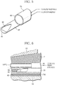
FIG. 5 is a perspective view showing the partially enlarged thread feed unit ofFIG. 4 . -
FIG. 6 is a drawing for explaining operation of the thread feed unit ofFIG. 4 . -
FIG. 7 is a graph showing CV values between Examples and Comparative Examples in terms of amount of menthol contained in a flavor-impregnated thread per filter rod. -
FIG. 8 is a graph showing CV values in Examples in which the impregnated amount of the menthol into the additive-impregnated thread is increased. - With reference to
FIG. 1 , a filter cigarette FC includes a cigarette C, and a filter F connected to a base end of the cigarette C by wrapping them with a tipping paper TP. The filter F includes a flavor-impregnated thread FT thereinside, and the flavor-impregnated thread FT contains a flavor. - Specifically, the filter F is produced by cutting a filter rod FR shown in
FIG. 2 . The filter rod FR includes a filter tow T formed of a bundle of acetate fibers, a wrapping material for wrapping the filter tow T into a rod shape, that is, a wrapping paper WP, and the flavor-impregnated thread FT disposed at a center of the filter tow T. -
FIG. 3 schematically shows a structural outline of a manufacturing machine of the filter rod FR, and a manufacturing method of the filter rod FR carried out by this manufacturing machine will be apparent from the following description according to the manufacturing machine. - The manufacturing machine includes a tow bale formed of acetate fibers, that is, the filter tow T in a web shape, and the filter tow T forms a
pile 12 on awagon 10. Aconveyance path 16 of the filter tow T extends from thepile 12 toward atow converging section 14, and in thisconveyance path 16, there are sequentially disposed aring guide 18, afirst banding jet 20, asecond banding jet 22,pretension rolls 24,blooming rolls 26, athird banding jet 28, anplasticizer applying unit 30, andconveyance rolls 32 in the order from thepile 12 of the filter tow T. - The first to
third banding jets pretension rolls 24 apply a predetermined tension to the filter tow T, and theblooming rolls 26 stretch out the filter tow T incorporation with thepretension rolls 24 therebetween. - When the filter tow T is conveyed through the applying
unit 30, the applyingunit 30 evenly applies liquid triacetin as a plasticizer to the filter tow T. Subsequently, the filter tow T is conveyed from theconveyance rolls 32 to thetow converging section 14. - In the present embodiment, the
tow converging section 14 includes atrumpet jet 34 and atrumpet guide 36, and thetrumpet jet 34 and thetrumpet guide 36 are disposed sequentially in the order from theconveyance rolls 32 in a manner as to be adjacent to each other. Thetrumpet jet 34 generates a compressed air flow thereinside to flow toward thetrumpet guide 36, and this compressed air flow converges the filter tow T conveyed from theconveyance rolls 32 into a cylindrical shape in the trumpet jet 34 (tow converging step) to introduce this filter tow T into thetrumpet guide 36. Subsequently, the filter tow T in a cylindrical shape entering thetrumpet guide 36 once expands in its radial direction, and then is conveyed toward awrapping section 38. - The
wrapping section 38 includes a formingbed 40, and this formingbed 40 extends in the horizontal direction, and has a startingend 40a located near thetrumpet guide 36 and aterminal end 40b spaced apart from thetrumpet guide 36. There is provided a forming groove (not shown) on an upper surface of the formingbed 40, and this forming groove extends from the startingend 40a to theterminal end 40b. Specifically, the forming groove is configured to be flat at the startingend 40a, but gradually increased in depth toward theterminal end 40b while its width is gradually decreased toward theterminal end 40b. Accordingly, the forming groove has a semi-circular cross section at theterminal end 40b. - A part of a
garniture tape 42 is disposed in the forming groove. Thisgarniture tape 42 is formed to be endless, and is wound around a driving drum 44 below the formingbed 40 at a predetermined winding angle, and is guided byplural guide rollers 46 at the same time. As apparent fromFIG. 3 , one of theguide rollers 46 is disposed immediately under thetrumpet guide 36. When the driving drum 44 is rotated, the above described part of thegarniture tape 42 travels on the forming groove of the formingbed 40 from the startingend 40a toward theterminal end 40b of the formingbed 40. - Meanwhile, on the forming
bed 40, a paper web PW is laid over thegarniture tape 42, and this paper web PW is led from a web roll WR throughplural guide rollers 48 onto thegarniture tape 42. One of theseguide rollers 48 is disposed adjacent to the above describedguide rollers 46 immediately under thetrumpet guide 36. -
Spray guns spray gun 50 applies a rail glue at the center of the paper web PW if viewed in the width direction of the paper web PW, while thespray gun 52 applies a lap glue at one side edge of the paper web PW. - The filter tow T fed through the
trumpet guide 36 is laid over the paper web PW at a merging position MP defined at or in front of the startingend 40a of the formingbed 40, and is bonded to the paper web PW with the rail glue. Thereafter, the paper web PW and the filter tow T travel together with thegarniture tape 42 on the formingbed 40 along the forming groove. - Immediately above the forming
bed 40, atong 54, a former 56, aheater 58, and a cooler 60 are disposed sequentially in the order from the startingend 40a. When filter tow T together with the paper web PW and the garniture tape T travel through thetong 54, thetong 54 squeezes the filter tow T from above (squeezing process) to compressively form the filter tow T into a rod shape in cooperation with the forming groove of the formingbed 40. At this time, thegarniture tape 42 and the paper web PW are bent in a U shape along the forming groove in a manner as to wrap up the filter tow T therewith from below. - Specifically, the
tong 54 defines a compressive forming passage in cooperation with the forming groove of the formingbed 40, and this compressive forming passage has a ceiling surface defined by thetong 54, and this ceiling surface has a shape of an upside-down forming groove. Accordingly, the compressive forming passage has a circular cross section at theterminal end 40b of the formingbed 40, that is, the terminal end of the compressive forming passage. - Thereafter, during conveyance of the filter tow T, the paper web PW, and the
garniture tape 42 all together through the former 56, the paper web PW is sequentially bent at its both side edges toward the filter tow T via thegarniture tape 42. Accordingly, the both side edges of the paper web PW are laid over each other on the filter tow T in a manner as to be adhesively bonded to each other with the aforementioned lap glue into a lap portion. At this time, the filter tow T is completely wrapped up with the paper web PW (wrapping step) into the tow rod TR. - Thereafter, the tow rod TR is provided with firm bonding at its lap portion during traveling through the
heater 58 and the cooler 60. - A cutting
unit 70 is disposed immediately downstream of thewrapping section 38, and the tow rod TR is conveyed through this cuttingunit 70. At this time, the cuttingunit 70 cuts the tow rod TR in a predetermined length into individual filter rods FR (cutting step). - The filter rods FR formed in this manner are received by a
receiver 72 from the cuttingunit 70, and thereafter, are conveyed toward a manufacturing machine of filter cigarettes, that is, a filter installation machine. - In this filter installation machine, the filter rod FR is cut into double filters, each having a length twice as long as that of the filter F. The double filter is disposed between two cigarettes C, and the cigarettes and the double filter are connected by being wrapped with the tipping paper to be formed into a double filter cigarette. Thereafter, the double filter cigarette is cut into individual filter cigarettes.
- Although not shown in
FIG. 1 , the aforementioned the filter rod FR manufacturing machine further includes athread feed unit 74 for embedding the flavor-impregnated thread FT in the tow rod TR, and the details of thisthread feed unit 74 are shown inFIG. 4 . - The
thread feed unit 74 includes a thread feed-outnozzle 76. The thread feed-outnozzle 76 is formed of a pipe member, and extends from the outside of thetow converging section 14 through thetow converging section 14 toward thewrapping section 38. - Specifically, the thread feed-out
nozzle 76 extends through thetrumpet jet 34 and thetrumpet guide 36, and has its both ends, that is, aninlet end 78 and a thread feed-out end (thread feed-out position) 80. Theinlet end 78 is located outside thetrumpet jet 34, and the thread feed-outend 80 is located more downstream than the above described merging position MP if viewed in the conveyance direction of the filter tow T. In the present embodiment, as apparent fromFIG. 4 , the thread feed-outend 80 enters thetong 54, and has an opening toward the downstream if viewed in the conveyance direction of the filter tow T. In addition, supposing a horizontal axial line (not shown) extending through the center of the circular terminal end in the aforementioned compressive forming passage, the thread feed-outend 80 is located on this axial line. - The thread feed-out
nozzle 76 receives a thread member S at theinlet end 78, and guides the received thread member S toward the thread feed-outend 80 so as to feed this thread member S from the thread feed-outend 80 into the tong 54 (thread feed-out step). The thread member S is fed from athread feed source 82, and led to theinlet end 78 of the thread feed-outnozzle 76. Although not shown inFIG. 4 , thethread feed source 82 includes a thread reel around which the thread S is wounded, and a feed roll and the like for feeding the thread member S from the thread reel along a guide path toward the thread feed-outnozzle 76; andFIG. 4 shows aguide roller 84 which is one of components defining the guide path, and thisguide roller 84 is disposed in the vicinity of theinlet end 78. - The
thread feed unit 74 further includes aliquid supply nozzle 86. Theliquid supply nozzle 86 is also formed of a pipe member, and extends along the thread feed-outnozzle 76. Specifically, theliquid supply nozzle 86 also extends through thetrumpet jet 34 and thetrumpet guide 36. As apparent fromFIG. 4 , in the present embodiment, theliquid supply nozzle 86 is located immediately under the thread feed-outnozzle 76, and has a front end located inside thetong 54, that is, a liquid discharge outlet (liquid discharging position) 88. Thisliquid discharge outlet 88 upwardly opens more downstream than the thread feed-outend 80. Hence, theliquid discharge outlet 88 is located immediately under the thread member S fed out from the thread feed-outend 80, and opens toward the lower surface of this thread member S. - Specifically, as apparent from
FIG. 5 , the front end of theliquid supply nozzle 86 is formed as aclosed end 90, and theliquid discharge outlet 88 is formed by obliquely cutting off the upper portion of theliquid supply nozzle 86 in a predetermined length from theclosed end 90. It should be noted that the lower portion of theclosed end 90 still remains. - Meanwhile, the
liquid supply nozzle 86 projects from thetrumpet jet 34, and is integrally supported together with the thread feed-outnozzle 76 by aholder plate 92. With this integral support of theliquid supply nozzle 86 and the thread feed-outnozzle 76 relative to theholder plate 92, by simply installing theliquid supply nozzle 86 and the thread feed-outnozzle 76 to theholder plate 92 at respective predetermined installation positions, it is possible to automatically determine positioning of theliquid discharge outlet 88 and the thread feed-outend 80 inside thetong 54, as well as relative positioning between the thread feed-outend 80 and theliquid discharge outlet 88. Accordingly, it is unnecessary to perform subsequent positional adjustment of the thread feed-outend 80 and theliquid discharge outlet 88, and it is possible to reduce variation in addition of the flavor liquid as well as it is effective for enhancement of productivity. - In addition, the
liquid supply nozzle 86 is connected to aliquid supply pipe 94 at theholder plate 92, and thisliquid supply pipe 94 extends toward aliquid supply source 96 so as to be connected to thisliquid supply source 96. Theliquid supply source 96 is capable of quantitatively supplying the flavor liquid through theliquid supply pipe 94 to theliquid supply nozzle 86. Although not shown inFIG. 4 , theliquid supply source 96 includes a liquid tank for reserving the flavor liquid, and a quantitative pump for supplying the flavor liquid from this liquid tank. - In the case of the present embodiment, the flavor liquid contains propylene glycol (PG) as a solvent and menthol (M) as a flavor dissolved in this propylene glycol.
- According to the above described
thread feed unit 74, the thread member S is fed from the thread feed-outend 80 of the thread feed-out nozzle 76 (thread feed-out step) into the center of the filter tow T entering the tong 54 (during the squeezing process); meanwhile, inFIG. 6 , the flavor liquid is discharged obliquely upward from theliquid discharge outlet 88 of theliquid supply nozzle 86, that is, toward the thread member S as shown by an arrow L inFIG. 6 (liquid discharging step). The flavor liquid discharged in this manner is applied to the thread member S, and is impregnated into the thread member S during the process of forming the tow rod TR. As a result, the tow rod TR, that is, the filter rod FR formed from the tow rod TR includes the flavor-impregnated thread FT at the center thereof. - As aforementioned, the flavor liquid is applied to the thread member S fed from the thread feed-out
end 80 of the thread feed-outnozzle 76, and subsequently, the thread member S to which the flavor liquid is applied, that is, the flavor-impregnated thread FT is surround by the filter tow T; thus the flavor-impregnated thread FT comes into contact with the filter tow T, but out of contact with the thread feed-outnozzle 76 and the peripheral mechanical components, such as thetong 54, thegarniture tape 42, and the formingbed 40. Hence, the flavor liquid once impregnated into the flavor-impregnated thread FT is unlikely to ooze out from the flavor-impregnated thread FT. Even if the flavor liquid oozes out from the flavor-impregnated thread FT, the flavor liquid in this state adheres to only the filter tow T, but is prevented from adhering to the thread feed-outnozzle 76 and the peripheral mechanical components. - Accordingly, if the flavor liquid is discharged from the
liquid discharge outlet 88 at a constant discharge rate, it is possible to effectively suppress variation in impregnated amount of the flavor liquid in terms of the amount of the flavor liquid impregnated into the flavor-impregnated thread FT per filter rod FR. As aforementioned, even if part of the flavor liquid adheres to the filter tow T, the content of the flavor liquid per filter rod FR becomes constant. - Furthermore, in the case of the present embodiment, because the
liquid discharge outlet 88 upwardly opens, the flavor liquid is prevented from dropping from theliquid discharge outlet 88 because of gravity even if the operation of the manufacturing machine is stopped, that is, the flavor liquid is stopped to be supplied from theliquid supply source 96. Hence, the peripheral mechanical components are prevented from becoming unclean with the flavor liquid; therefore, it is possible to reduce load required for cleaning the mechanical components. - With respect to filter rods FR of Examples E1, E2 manufactured by the aforementioned manufacturing machine, the following Table 1 shows measurement results of respective average values of the amount of menthol M contained in the flavor-impregnated thread FT and respective CV values thereof. In Table 1, Qo and M amount respectively represent a target content and actual impregnated amount of the menthol M per flavor-impregnated thread FT.
- Table 1 also shows results of the same measurement on filter rods of Comparative Examples C1 to C3 manufactured by the manufacturing machine of Patent Document 1. The difference between Examples E1 and E2, and the differences among Comparative Examples C1 to C3 represent respective differences in manufacturing date.
[Table 1] Qo (g/filter rod) Number of filter rods N M amount (g/filter rod) Example E1 Average 0.026 10 0.024 CV value(%) 2.81 Example E2 Average 0.026 10 0.025 CV value(%) 3.60 Comparative Example C1 Average 0.026 5 0.0245 CV value(%) 9.65 Comparative Example C2 Average 0.026 5 0.0245 CV value(%) 17.57 Comparative Example C3 Average 0.026 5 0.0253 CV value(%) 12.18 -
FIG. 7 shows the CV values of the menthol M in Table 1 in a bar graph. As apparent fromFIG. 7 , the CV values of Examples E1, E2 are significantly reduced compared with the CV values of Comparative Examples C1 to C3. This means that the amount of the menthol M contained per filter rod FR, that is, per filter F becomes stable, which enables manufacturing of the filter cigarettes FC in high quality. -
FIG. 8 shows the CV values of the menthol M in Examples E3, E4 with respect to the filter rods FR of Examples E3, E4 manufactured in such a manner that the target impregnated amount Qo of the flavor liquid was changed to 0.056g/filter rod. As apparent fromFIG. 8 , if the target impregnated amount Qo of the menthol M is increased, the manufacturing machine of the present embodiment can further reduce the CV value of the menthol M. - The present invention is not limited to the manufacturing machine and the manufacturing method according to the aforementioned embodiment, and various modifications may be made within the scope of the appended claims.
- For example, the
liquid discharge outlet 88 of theliquid supply nozzle 86 may upwardly open in the vertical direction, or may open toward a side surface of the thread member S. There may be provided multipleliquid supply nozzles 86. - In one exemplary embodiment, the thread feed-out
nozzle 76 and theliquid supply nozzle 86 extend together through thetrumpet jet 34 and thetrumpet guide 36 into thetong 54, but at least the thread feed-outnozzle 76 may once enter between thetong 54 and thetrumpet guide 36 or between thetrumpet guide 36 and thetrumpet jet 34 in a direction vertical to the conveyance direction of the filter tow T, and then may be bent to extend into thetong 54 along the conveyance direction of the filter tow T. - In addition, the additive liquid to be impregnated into the thread member may contain other flavors than the menthol, and the solvent is not limited to propylene glycol. Although not limited to specific one, the combination ratio between the menthol and the solvent may be 9:1 to 5:5.
-
- 14
- tow converging section
- 38
- wrapping section
- 54
- tong
- 70
- cutting unit
- 76
- thread feed-out nozzle
- 80
- thread feed-out end
- 86
- liquid supply nozzle
- 88
- liquid discharge outlet
- FR
- filter rod
- FT
- flavor-impregnated thread
- S
- thread member
- T
- filter tow
Claims (8)
- A filter rod manufacturing machine comprising:a tow converging section (14) for converging a filter tow during conveyance of the filter tow (T) in a web shape;a wrapping section (38) for respectively receiving the converged filter tow (T) and a wrapping material (PW) at a merging position (MP) defined to be downstream of the tow converging section (14) if viewed in a conveyance direction of the filter tow (T) so as to wrap the filter tow (T) with the wrapping material (PW) into a tow rod (TR);a thread feed-out nozzle (76) for guiding a thread member (S) toward the wrapping section (38) to form the tow rod including the thread member thereinside;a liquid supply nozzle (86) for supplying an additive liquid to be impregnated into the thread member; anda cutting unit (70) so located downstream of the wrapping section (38) as to cut the tow rod (TR) into filter rods (FR), each having a predetermined length,characterized in thatthe thread feed-out nozzle (76) includes a thread feed-out end (80) located more downstream than the merging position (MP), the thread feed-out end (80) feeding the thread member (S) into the filter tow (T), andthe liquid supply nozzle (86) includes a liquid discharge outlet (88) so located more downstream than the thread feed-out end (80) as to discharge the additive liquid toward the thread member (S) fed from the thread feed-out end (80).
- The filter rod manufacturing machine according to claim 1, wherein
the wrapping section (38) includes a tong (54) so located downstream of the merging position (MP) as to squeeze the filter tow (T) into a rod shape, and
the thread feed-out end (80) and the liquid discharge outlet (88) are disposed together inside the tong (54). - The filter rod manufacturing machine according to claim 2, wherein
the liquid discharge outlet (88) is disposed at a front end of the liquid supply nozzle. - The filter rod manufacturing machine according to claim 3, wherein
the liquid supply nozzle (86) extends immediately under the thread feed-out nozzle (76), and the liquid discharge outlet (88) upwardly opens. - The filter rod manufacturing machine according to claim 1, wherein
the liquid supply nozzle (86) and the thread feed-out nozzle (76) are integrally supported by a common holder plate (92). - A filter rod manufacturing method comprising:a tow converging step (14) of converging a filter tow (T) during conveyance of the filter tow (T) in a web shape;a wrapping step (38) of respectively receiving the converged filter tow (T) and a wrapping material (PW) at a merging position (MP) so as to wrap the filter tow (T) with the wrapping material (PW) into a tow rod (TR);a thread feed-out step (76) of feeding a thread member (S) into the filter tow (T) at a thread feed-out position (80) to form the tow rod (TR) including the thread member (S) thereinside;a liquid discharging step (86) of discharging an additive liquid toward the thread member (S) at a liquid discharging position (88) to impregnate the discharged additive liquid into the thread member (S); anda cutting step (70) of cutting the tow rod (TR) formed in the wrapping step (38) into filter rods (FR), each having a predetermined length,characterized in thatthe tread feed-out position (80) is defined to be more downstream than the merging position (MP), andthe liquid discharging positon (88) is defined to be more downstream than the thread feed-out position (80).
- The filter rod manufacturing method according to claim 6, wherein
the wrapping step (38) includes a squeezing process (54) of squeezing the filter tow (T) into a rod shape at a position downstream of the merging position (MP), and
the thread feed-out step (76) and the liquid discharging step (86) are carried out during the squeezing process (54). - The filter rod manufacturing method according to claim 7, wherein
in the liquid discharging step (86), the additive liquid is upwardly discharged at the liquid discharging position (88).
Applications Claiming Priority (1)
| Application Number | Priority Date | Filing Date | Title |
|---|---|---|---|
| PCT/JP2012/083609 WO2014102926A1 (en) | 2012-12-26 | 2012-12-26 | Filter rod manufacturing machine and filter rod manufacturing method |
Publications (3)
| Publication Number | Publication Date |
|---|---|
| EP2910133A1 EP2910133A1 (en) | 2015-08-26 |
| EP2910133A4 EP2910133A4 (en) | 2016-06-15 |
| EP2910133B1 true EP2910133B1 (en) | 2020-03-04 |
Family
ID=51020085
Family Applications (1)
| Application Number | Title | Priority Date | Filing Date |
|---|---|---|---|
| EP12890930.6A Active EP2910133B1 (en) | 2012-12-26 | 2012-12-26 | Filter rod manufacturing machine and filter rod manufacturing method |
Country Status (3)
| Country | Link |
|---|---|
| EP (1) | EP2910133B1 (en) |
| JP (1) | JP5888800B2 (en) |
| WO (1) | WO2014102926A1 (en) |
Families Citing this family (6)
| Publication number | Priority date | Publication date | Assignee | Title |
|---|---|---|---|---|
| DE102015201781A1 (en) * | 2015-02-02 | 2016-08-04 | Hauni Maschinenbau Ag | Method and device for producing filters of the tobacco processing industry |
| CN105595415A (en) * | 2016-01-15 | 2016-05-25 | 红云红河烟草(集团)有限责任公司 | Method for preparing honey fragrance cigarette incense thread by means of litchi nectar |
| CN109793276B (en) * | 2019-03-20 | 2021-02-19 | 红云红河烟草(集团)有限责任公司 | Guide wire tongue gel filling device |
| KR102393804B1 (en) * | 2019-12-19 | 2022-05-03 | 주식회사 케이티앤지 | A manufacturing apparatus for a tube filter and manufacturing method for the tube filter |
| KR102533111B1 (en) * | 2020-02-17 | 2023-05-16 | 주식회사 케이티앤지 | A smoking article including flavored tube filter and manufacturing method thereof |
| US20230371578A1 (en) * | 2020-10-09 | 2023-11-23 | Philip Morris Products S.A. | Applying an additive upon shaping sheet material into a rod incorporating a heatable susceptor |
Family Cites Families (7)
| Publication number | Priority date | Publication date | Assignee | Title |
|---|---|---|---|---|
| GB2020158B (en) | 1978-04-21 | 1982-11-24 | Cigarette Components Ltd | Production of tobacco smoke filters |
| US4549875A (en) * | 1983-06-02 | 1985-10-29 | R. J. Reynolds Tobacco Co. | Manufacture of tobacco smoke filters |
| US7074170B2 (en) * | 2002-03-29 | 2006-07-11 | Philip Morris Usa Inc. | Method and apparatus for making cigarette filters with a centrally located flavored element |
| PL1958523T3 (en) * | 2006-08-04 | 2012-09-28 | Philip Morris Products Sa | Multi-component filter providing multiple flavour enhancement |
| GB0714530D0 (en) * | 2007-07-25 | 2007-09-05 | British American Tobacco Co | New apparatus and method |
| GB0905210D0 (en) * | 2009-03-26 | 2009-05-13 | British American Tobacco Co | Rod for a smoking article and method and apparatus for manufacture |
| WO2012164645A1 (en) * | 2011-05-27 | 2012-12-06 | 日本たばこ産業株式会社 | Filter manufacturing device, filter manufacturing method, and filter |
-
2012
- 2012-12-26 WO PCT/JP2012/083609 patent/WO2014102926A1/en active Application Filing
- 2012-12-26 JP JP2014553933A patent/JP5888800B2/en not_active Expired - Fee Related
- 2012-12-26 EP EP12890930.6A patent/EP2910133B1/en active Active
Non-Patent Citations (1)
| Title |
|---|
| None * |
Also Published As
| Publication number | Publication date |
|---|---|
| EP2910133A1 (en) | 2015-08-26 |
| WO2014102926A1 (en) | 2014-07-03 |
| JP5888800B2 (en) | 2016-03-22 |
| JPWO2014102926A1 (en) | 2017-01-12 |
| EP2910133A4 (en) | 2016-06-15 |
Similar Documents
| Publication | Publication Date | Title |
|---|---|---|
| EP2910133B1 (en) | Filter rod manufacturing machine and filter rod manufacturing method | |
| US10039316B2 (en) | Cigarette filter manufacturing apparatus and cigarette filter manufacturing method | |
| JP4222524B2 (en) | Filter rod making machine | |
| KR102072382B1 (en) | Apparatus and method for supplying a continuous web of crimped sheet material | |
| EP2057908A1 (en) | Rod forming machine | |
| EP2606755B1 (en) | Feed unit for feeding thread to an automatic cigarette filter manufacturing machine | |
| RU2355265C1 (en) | Cigarette production machine | |
| KR102226828B1 (en) | Method and appratus for forming a filter rod | |
| JP5640090B2 (en) | Filter manufacturing apparatus, filter manufacturing method, and filter | |
| CN205233452U (en) | Eliminate device of no paper filter rod strap indentation | |
| US4575368A (en) | Method and apparatus for making filters | |
| CN107734980B (en) | Improved filter rod making machine for processing rigid wrapper web material | |
| DE10156691A1 (en) | Glue nozzle for applying glue to filter paper edges is designed with adhesive exiting outlet opening in direction across delivery direction | |
| CN104872818B (en) | Method and device for producing a rod for the tobacco processing industry | |
| CN108601393B (en) | Machine for making cigarette filters and method for making cigarette filters | |
| KR20180044351A (en) | Filter rod drying method | |
| KR102614970B1 (en) | A garniture device and a machine and a method for manufacturing multi-segment filter rods | |
| US20190328035A1 (en) | A feeding device for feeding a continuous strip into a continuous fibrous band in a tobacco industry machine for manufacturing rod-like elements and a machine for manufacturing rod-like elements | |
| TWI468120B (en) | Method for manufacturing filter cigarette as well as filter and filter cigarette | |
| PL241632B1 (en) | Formatting device, machine for manufacturing multi-segmented cigarette filter slabs and method for manufacturing multi-segmented cigarette filter slabs |
Legal Events
| Date | Code | Title | Description |
|---|---|---|---|
| PUAI | Public reference made under article 153(3) epc to a published international application that has entered the european phase |
Free format text: ORIGINAL CODE: 0009012 |
|
| 17P | Request for examination filed |
Effective date: 20150522 |
|
| AK | Designated contracting states |
Kind code of ref document: A1 Designated state(s): AL AT BE BG CH CY CZ DE DK EE ES FI FR GB GR HR HU IE IS IT LI LT LU LV MC MK MT NL NO PL PT RO RS SE SI SK SM TR |
|
| AX | Request for extension of the european patent |
Extension state: BA ME |
|
| DAX | Request for extension of the european patent (deleted) | ||
| RA4 | Supplementary search report drawn up and despatched (corrected) |
Effective date: 20160512 |
|
| RIC1 | Information provided on ipc code assigned before grant |
Ipc: A24D 3/02 20060101AFI20160506BHEP Ipc: A24D 3/04 20060101ALI20160506BHEP |
|
| GRAP | Despatch of communication of intention to grant a patent |
Free format text: ORIGINAL CODE: EPIDOSNIGR1 |
|
| STAA | Information on the status of an ep patent application or granted ep patent |
Free format text: STATUS: GRANT OF PATENT IS INTENDED |
|
| INTG | Intention to grant announced |
Effective date: 20191017 |
|
| GRAS | Grant fee paid |
Free format text: ORIGINAL CODE: EPIDOSNIGR3 |
|
| GRAA | (expected) grant |
Free format text: ORIGINAL CODE: 0009210 |
|
| STAA | Information on the status of an ep patent application or granted ep patent |
Free format text: STATUS: THE PATENT HAS BEEN GRANTED |
|
| AK | Designated contracting states |
Kind code of ref document: B1 Designated state(s): AL AT BE BG CH CY CZ DE DK EE ES FI FR GB GR HR HU IE IS IT LI LT LU LV MC MK MT NL NO PL PT RO RS SE SI SK SM TR |
|
| REG | Reference to a national code |
Ref country code: GB Ref legal event code: FG4D |
|
| REG | Reference to a national code |
Ref country code: CH Ref legal event code: EP |
|
| REG | Reference to a national code |
Ref country code: AT Ref legal event code: REF Ref document number: 1239382 Country of ref document: AT Kind code of ref document: T Effective date: 20200315 |
|
| REG | Reference to a national code |
Ref country code: DE Ref legal event code: R096 Ref document number: 602012068310 Country of ref document: DE |
|
| REG | Reference to a national code |
Ref country code: IE Ref legal event code: FG4D |
|
| PG25 | Lapsed in a contracting state [announced via postgrant information from national office to epo] |
Ref country code: FI Free format text: LAPSE BECAUSE OF FAILURE TO SUBMIT A TRANSLATION OF THE DESCRIPTION OR TO PAY THE FEE WITHIN THE PRESCRIBED TIME-LIMIT Effective date: 20200304 Ref country code: RS Free format text: LAPSE BECAUSE OF FAILURE TO SUBMIT A TRANSLATION OF THE DESCRIPTION OR TO PAY THE FEE WITHIN THE PRESCRIBED TIME-LIMIT Effective date: 20200304 Ref country code: NO Free format text: LAPSE BECAUSE OF FAILURE TO SUBMIT A TRANSLATION OF THE DESCRIPTION OR TO PAY THE FEE WITHIN THE PRESCRIBED TIME-LIMIT Effective date: 20200604 |
|
| REG | Reference to a national code |
Ref country code: NL Ref legal event code: MP Effective date: 20200304 |
|
| PG25 | Lapsed in a contracting state [announced via postgrant information from national office to epo] |
Ref country code: BG Free format text: LAPSE BECAUSE OF FAILURE TO SUBMIT A TRANSLATION OF THE DESCRIPTION OR TO PAY THE FEE WITHIN THE PRESCRIBED TIME-LIMIT Effective date: 20200604 Ref country code: GR Free format text: LAPSE BECAUSE OF FAILURE TO SUBMIT A TRANSLATION OF THE DESCRIPTION OR TO PAY THE FEE WITHIN THE PRESCRIBED TIME-LIMIT Effective date: 20200605 Ref country code: SE Free format text: LAPSE BECAUSE OF FAILURE TO SUBMIT A TRANSLATION OF THE DESCRIPTION OR TO PAY THE FEE WITHIN THE PRESCRIBED TIME-LIMIT Effective date: 20200304 Ref country code: LV Free format text: LAPSE BECAUSE OF FAILURE TO SUBMIT A TRANSLATION OF THE DESCRIPTION OR TO PAY THE FEE WITHIN THE PRESCRIBED TIME-LIMIT Effective date: 20200304 Ref country code: HR Free format text: LAPSE BECAUSE OF FAILURE TO SUBMIT A TRANSLATION OF THE DESCRIPTION OR TO PAY THE FEE WITHIN THE PRESCRIBED TIME-LIMIT Effective date: 20200304 |
|
| REG | Reference to a national code |
Ref country code: LT Ref legal event code: MG4D |
|
| PG25 | Lapsed in a contracting state [announced via postgrant information from national office to epo] |
Ref country code: NL Free format text: LAPSE BECAUSE OF FAILURE TO SUBMIT A TRANSLATION OF THE DESCRIPTION OR TO PAY THE FEE WITHIN THE PRESCRIBED TIME-LIMIT Effective date: 20200304 |
|
| PG25 | Lapsed in a contracting state [announced via postgrant information from national office to epo] |
Ref country code: SK Free format text: LAPSE BECAUSE OF FAILURE TO SUBMIT A TRANSLATION OF THE DESCRIPTION OR TO PAY THE FEE WITHIN THE PRESCRIBED TIME-LIMIT Effective date: 20200304 Ref country code: ES Free format text: LAPSE BECAUSE OF FAILURE TO SUBMIT A TRANSLATION OF THE DESCRIPTION OR TO PAY THE FEE WITHIN THE PRESCRIBED TIME-LIMIT Effective date: 20200304 Ref country code: LT Free format text: LAPSE BECAUSE OF FAILURE TO SUBMIT A TRANSLATION OF THE DESCRIPTION OR TO PAY THE FEE WITHIN THE PRESCRIBED TIME-LIMIT Effective date: 20200304 Ref country code: EE Free format text: LAPSE BECAUSE OF FAILURE TO SUBMIT A TRANSLATION OF THE DESCRIPTION OR TO PAY THE FEE WITHIN THE PRESCRIBED TIME-LIMIT Effective date: 20200304 Ref country code: SM Free format text: LAPSE BECAUSE OF FAILURE TO SUBMIT A TRANSLATION OF THE DESCRIPTION OR TO PAY THE FEE WITHIN THE PRESCRIBED TIME-LIMIT Effective date: 20200304 Ref country code: PT Free format text: LAPSE BECAUSE OF FAILURE TO SUBMIT A TRANSLATION OF THE DESCRIPTION OR TO PAY THE FEE WITHIN THE PRESCRIBED TIME-LIMIT Effective date: 20200729 Ref country code: CZ Free format text: LAPSE BECAUSE OF FAILURE TO SUBMIT A TRANSLATION OF THE DESCRIPTION OR TO PAY THE FEE WITHIN THE PRESCRIBED TIME-LIMIT Effective date: 20200304 Ref country code: RO Free format text: LAPSE BECAUSE OF FAILURE TO SUBMIT A TRANSLATION OF THE DESCRIPTION OR TO PAY THE FEE WITHIN THE PRESCRIBED TIME-LIMIT Effective date: 20200304 Ref country code: IS Free format text: LAPSE BECAUSE OF FAILURE TO SUBMIT A TRANSLATION OF THE DESCRIPTION OR TO PAY THE FEE WITHIN THE PRESCRIBED TIME-LIMIT Effective date: 20200704 |
|
| REG | Reference to a national code |
Ref country code: AT Ref legal event code: MK05 Ref document number: 1239382 Country of ref document: AT Kind code of ref document: T Effective date: 20200304 |
|
| REG | Reference to a national code |
Ref country code: DE Ref legal event code: R097 Ref document number: 602012068310 Country of ref document: DE |
|
| PLBE | No opposition filed within time limit |
Free format text: ORIGINAL CODE: 0009261 |
|
| STAA | Information on the status of an ep patent application or granted ep patent |
Free format text: STATUS: NO OPPOSITION FILED WITHIN TIME LIMIT |
|
| PG25 | Lapsed in a contracting state [announced via postgrant information from national office to epo] |
Ref country code: IT Free format text: LAPSE BECAUSE OF FAILURE TO SUBMIT A TRANSLATION OF THE DESCRIPTION OR TO PAY THE FEE WITHIN THE PRESCRIBED TIME-LIMIT Effective date: 20200304 Ref country code: AT Free format text: LAPSE BECAUSE OF FAILURE TO SUBMIT A TRANSLATION OF THE DESCRIPTION OR TO PAY THE FEE WITHIN THE PRESCRIBED TIME-LIMIT Effective date: 20200304 Ref country code: DK Free format text: LAPSE BECAUSE OF FAILURE TO SUBMIT A TRANSLATION OF THE DESCRIPTION OR TO PAY THE FEE WITHIN THE PRESCRIBED TIME-LIMIT Effective date: 20200304 |
|
| 26N | No opposition filed |
Effective date: 20201207 |
|
| PG25 | Lapsed in a contracting state [announced via postgrant information from national office to epo] |
Ref country code: SI Free format text: LAPSE BECAUSE OF FAILURE TO SUBMIT A TRANSLATION OF THE DESCRIPTION OR TO PAY THE FEE WITHIN THE PRESCRIBED TIME-LIMIT Effective date: 20200304 Ref country code: PL Free format text: LAPSE BECAUSE OF FAILURE TO SUBMIT A TRANSLATION OF THE DESCRIPTION OR TO PAY THE FEE WITHIN THE PRESCRIBED TIME-LIMIT Effective date: 20200304 |
|
| REG | Reference to a national code |
Ref country code: DE Ref legal event code: R119 Ref document number: 602012068310 Country of ref document: DE |
|
| REG | Reference to a national code |
Ref country code: CH Ref legal event code: PL |
|
| GBPC | Gb: european patent ceased through non-payment of renewal fee |
Effective date: 20201226 |
|
| PG25 | Lapsed in a contracting state [announced via postgrant information from national office to epo] |
Ref country code: MC Free format text: LAPSE BECAUSE OF FAILURE TO SUBMIT A TRANSLATION OF THE DESCRIPTION OR TO PAY THE FEE WITHIN THE PRESCRIBED TIME-LIMIT Effective date: 20200304 |
|
| REG | Reference to a national code |
Ref country code: BE Ref legal event code: MM Effective date: 20201231 |
|
| PG25 | Lapsed in a contracting state [announced via postgrant information from national office to epo] |
Ref country code: FR Free format text: LAPSE BECAUSE OF NON-PAYMENT OF DUE FEES Effective date: 20201231 Ref country code: LU Free format text: LAPSE BECAUSE OF NON-PAYMENT OF DUE FEES Effective date: 20201226 Ref country code: IE Free format text: LAPSE BECAUSE OF NON-PAYMENT OF DUE FEES Effective date: 20201226 |
|
| PG25 | Lapsed in a contracting state [announced via postgrant information from national office to epo] |
Ref country code: DE Free format text: LAPSE BECAUSE OF NON-PAYMENT OF DUE FEES Effective date: 20210701 Ref country code: CH Free format text: LAPSE BECAUSE OF NON-PAYMENT OF DUE FEES Effective date: 20201231 Ref country code: GB Free format text: LAPSE BECAUSE OF NON-PAYMENT OF DUE FEES Effective date: 20201226 Ref country code: LI Free format text: LAPSE BECAUSE OF NON-PAYMENT OF DUE FEES Effective date: 20201231 |
|
| PG25 | Lapsed in a contracting state [announced via postgrant information from national office to epo] |
Ref country code: TR Free format text: LAPSE BECAUSE OF FAILURE TO SUBMIT A TRANSLATION OF THE DESCRIPTION OR TO PAY THE FEE WITHIN THE PRESCRIBED TIME-LIMIT Effective date: 20200304 Ref country code: MT Free format text: LAPSE BECAUSE OF FAILURE TO SUBMIT A TRANSLATION OF THE DESCRIPTION OR TO PAY THE FEE WITHIN THE PRESCRIBED TIME-LIMIT Effective date: 20200304 Ref country code: CY Free format text: LAPSE BECAUSE OF FAILURE TO SUBMIT A TRANSLATION OF THE DESCRIPTION OR TO PAY THE FEE WITHIN THE PRESCRIBED TIME-LIMIT Effective date: 20200304 |
|
| PG25 | Lapsed in a contracting state [announced via postgrant information from national office to epo] |
Ref country code: MK Free format text: LAPSE BECAUSE OF FAILURE TO SUBMIT A TRANSLATION OF THE DESCRIPTION OR TO PAY THE FEE WITHIN THE PRESCRIBED TIME-LIMIT Effective date: 20200304 Ref country code: AL Free format text: LAPSE BECAUSE OF FAILURE TO SUBMIT A TRANSLATION OF THE DESCRIPTION OR TO PAY THE FEE WITHIN THE PRESCRIBED TIME-LIMIT Effective date: 20200304 |
|
| PG25 | Lapsed in a contracting state [announced via postgrant information from national office to epo] |
Ref country code: BE Free format text: LAPSE BECAUSE OF NON-PAYMENT OF DUE FEES Effective date: 20201231 |