EP1978833B1 - Deflecting device for a continuous filter tow, method for conveying and deflecting at least one continuous filter tow, and device for the production of cigarette filters - Google Patents
Deflecting device for a continuous filter tow, method for conveying and deflecting at least one continuous filter tow, and device for the production of cigarette filters Download PDFInfo
- Publication number
- EP1978833B1 EP1978833B1 EP06818621A EP06818621A EP1978833B1 EP 1978833 B1 EP1978833 B1 EP 1978833B1 EP 06818621 A EP06818621 A EP 06818621A EP 06818621 A EP06818621 A EP 06818621A EP 1978833 B1 EP1978833 B1 EP 1978833B1
- Authority
- EP
- European Patent Office
- Prior art keywords
- machine
- funnel
- tubular body
- filtering material
- deflection
- Prior art date
- Legal status (The legal status is an assumption and is not a legal conclusion. Google has not performed a legal analysis and makes no representation as to the accuracy of the status listed.)
- Active
Links
- 238000004519 manufacturing process Methods 0.000 title claims description 5
- 235000019504 cigarettes Nutrition 0.000 title claims description 4
- 238000000034 method Methods 0.000 title description 4
- 239000000463 material Substances 0.000 claims description 58
- 239000000126 substance Substances 0.000 claims description 8
- 238000001914 filtration Methods 0.000 claims 11
- 239000007921 spray Substances 0.000 claims 1
- 238000002347 injection Methods 0.000 description 9
- 239000007924 injection Substances 0.000 description 9
- XLYOFNOQVPJJNP-UHFFFAOYSA-N water Substances O XLYOFNOQVPJJNP-UHFFFAOYSA-N 0.000 description 7
- URAYPUMNDPQOKB-UHFFFAOYSA-N triacetin Chemical compound CC(=O)OCC(OC(C)=O)COC(C)=O URAYPUMNDPQOKB-UHFFFAOYSA-N 0.000 description 6
- 239000000654 additive Substances 0.000 description 5
- 230000010349 pulsation Effects 0.000 description 5
- OKTJSMMVPCPJKN-UHFFFAOYSA-N Carbon Chemical compound [C] OKTJSMMVPCPJKN-UHFFFAOYSA-N 0.000 description 4
- 230000000694 effects Effects 0.000 description 4
- 230000003750 conditioning effect Effects 0.000 description 3
- 238000005520 cutting process Methods 0.000 description 3
- 235000013773 glyceryl triacetate Nutrition 0.000 description 3
- 239000001087 glyceryl triacetate Substances 0.000 description 3
- 238000003860 storage Methods 0.000 description 3
- 229960002622 triacetin Drugs 0.000 description 3
- 230000000712 assembly Effects 0.000 description 2
- 238000000429 assembly Methods 0.000 description 2
- 230000008901 benefit Effects 0.000 description 2
- 238000013016 damping Methods 0.000 description 2
- 230000006872 improvement Effects 0.000 description 2
- 230000004048 modification Effects 0.000 description 2
- 238000012986 modification Methods 0.000 description 2
- 239000004014 plasticizer Substances 0.000 description 2
- 238000003825 pressing Methods 0.000 description 2
- 230000001154 acute effect Effects 0.000 description 1
- 238000007792 addition Methods 0.000 description 1
- 230000008859 change Effects 0.000 description 1
- 230000003247 decreasing effect Effects 0.000 description 1
- 238000009826 distribution Methods 0.000 description 1
- 210000003608 fece Anatomy 0.000 description 1
- 239000000796 flavoring agent Substances 0.000 description 1
- 235000019634 flavors Nutrition 0.000 description 1
- 238000005243 fluidization Methods 0.000 description 1
- 230000007062 hydrolysis Effects 0.000 description 1
- 238000006460 hydrolysis reaction Methods 0.000 description 1
- 230000008092 positive effect Effects 0.000 description 1
- 230000008569 process Effects 0.000 description 1
- 230000009467 reduction Effects 0.000 description 1
- 238000000926 separation method Methods 0.000 description 1
- 238000005507 spraying Methods 0.000 description 1
- 230000017260 vegetative to reproductive phase transition of meristem Effects 0.000 description 1
Images


Classifications
-
- A—HUMAN NECESSITIES
- A24—TOBACCO; CIGARS; CIGARETTES; SIMULATED SMOKING DEVICES; SMOKERS' REQUISITES
- A24D—CIGARS; CIGARETTES; TOBACCO SMOKE FILTERS; MOUTHPIECES FOR CIGARS OR CIGARETTES; MANUFACTURE OF TOBACCO SMOKE FILTERS OR MOUTHPIECES
- A24D3/00—Tobacco smoke filters, e.g. filter-tips, filtering inserts; Filters specially adapted for simulated smoking devices; Mouthpieces for cigars or cigarettes
- A24D3/02—Manufacture of tobacco smoke filters
- A24D3/0204—Preliminary operations before the filter rod forming process, e.g. crimping, blooming
- A24D3/0212—Applying additives to filter materials
- A24D3/022—Applying additives to filter materials with liquid additives, e.g. application of plasticisers
-
- A—HUMAN NECESSITIES
- A24—TOBACCO; CIGARS; CIGARETTES; SIMULATED SMOKING DEVICES; SMOKERS' REQUISITES
- A24D—CIGARS; CIGARETTES; TOBACCO SMOKE FILTERS; MOUTHPIECES FOR CIGARS OR CIGARETTES; MANUFACTURE OF TOBACCO SMOKE FILTERS OR MOUTHPIECES
- A24D3/00—Tobacco smoke filters, e.g. filter-tips, filtering inserts; Filters specially adapted for simulated smoking devices; Mouthpieces for cigars or cigarettes
- A24D3/02—Manufacture of tobacco smoke filters
- A24D3/027—Multiple line manufacturing devices
Definitions
- the invention relates to a deflection device for conveying and deflecting at least one filter tow strand.
- This device can be coupled with a format part, in particular with an intake system of a machine for the production of filter rods.
- the invention relates to a machine comprising such a deflection device and a method for conveying and deflecting at least one filter tow.
- a deflection device of the type mentioned is, for example, from the WO 2005/058 079 A1 known.
- This deflection device is used in double-strand machines, which comprise two format sections for forming continuous filter rods and a filter material supply line for each format section.
- the supply lines receive the filter material from a conveyor line which extends between an inlet region of the supply lines and a storage area of two filter material bales.
- a blower which is provided in the inlet area to pull the two Lunten transversely in two strips of filter material.
- the two strips are blown along respective feeds by a pressing device, then by an expander, in the air in the strips to increase their volume, and finally conveyed by a conditioning device where chemical substances are added to the strip to give the filter material flavor and formability.
- Each feeder is connected to the format section by a diverter which serves to convert and stabilize the strips into strands of filter material.
- the diverter receives a strip from the feeder and conveys this, in the shape of a uniform strand, on a strip of previously rubberized paper in the format section.
- the diverter unit typically includes a hopper for each feeder into which the strip is inserted and compacted, thereby forming the filter material strand.
- air can be blown into the hopper, such as in the US 4,522,616 A1 described.
- the paper strip is wound in the format section transversally around the strand, whereby a continuous filter rod is formed.
- a control unit controls the density of the filter rods.
- a cutting head cuts the bars into individual filter sections.
- the reduction of the distance between the two strands in the deflection unit of the machine according to WO 2005/058 079 A1 is effected by two pulleys, which have a V-shaped cross-section.
- the two deflection rollers interact with the curvature arcs of the two inlet funnels and receive the filter tow strand from two transport rollers.
- the filter material strand is therefore fed mechanically into the two inlet funnel.
- Filter rods made on known filter rod machines with a deflection unit described above have insufficient homogeneity.
- the invention has for its object to further develop the aforementioned deflection such that filter rods can be produced with improved homogeneity. Moreover, the device with comparatively be easy to implement at a low cost. Another object of the invention is to provide a machine with such a deflection device and a method for conveying and deflecting at least one filter tow.
- the above-mentioned object is achieved by a machine for producing cigarette filters according to independent claim 1.
- An essential aspect of the invention is the provision of a transport device for pneumatically conveying the at least one filter strand and a deflection device which cooperates with the transport device for pneumatically driven deflection of the filter tow strand.
- the combination of pneumatic transport with strand deflection results in increased fluidization of the material, resulting in a very homogeneous filter material.
- the draw resistance and draw resistance spread of a filter rod are significantly improved, which is obtainable by a filter rod machine with the inventive deflection device.
- the deflection device according to the invention can be realized cost-effectively, so that the total cost of the filter rod machine can be reduced.
- the inventive deflection device can be used in a simple manner in known filter rod machines, wherein only the existing deflection unit of such a machine is replaced by the deflection device according to the invention.
- the known deflection device according to WO 2005/058 079 A1 designed to feed the filter tow line mechanically into the format section of the machine.
- the known deflection device couples to a mechanical conveyor with a deflection.
- This filter rod machine is therefore unable to produce a filter material which is comparable in terms of homogeneity, draw resistance and draw resistance scattering to a filter material obtainable by a filter rod machine comprising a deflection device according to the invention.
- the deflection device also works on a mechanical basis using a pulley.
- the strand coming from the pulley is introduced into a hopper by a forward flow of air from a nozzle located immediately in front of the hopper. This means that the nozzle is used exclusively to insert the strand into the hopper, whereby no distraction or deflection of the strand takes place.
- the deflection device is adapted such that the deflection of the at least one filter tow strand has at least one horizontal component. It has been found that due to the horizontal component of the deflection, the draw resistance and draw resistance scattering can be further improved. In contrast, the deflection device according to US 4,522,616 only a vertical deflection of the strand before.
- the transport device may have at least one pneumatically operated transport nozzle, whereby a particularly simple technical implementation the transport device is achieved since conventional transport nozzles can be used.
- the transport device has two transport nozzles, which are arranged in the region of the inlet side and the outlet side of the device.
- the two nozzles can be operated at different pressures to influence the properties of the filter tow.
- the deflection device comprises at least one curvature arc which determines the conveying path of the filter tow strand at least in sections.
- the use of a curvature arc in connection with the deflection device has the advantage that a continuous deflection of the filter tow strand is achieved.
- any component having a continuously curved configuration that causes a deflection of an airflow such as a baffle, is suitable for implementing the baffle.
- the curvature arc can be connected to the transport nozzle provided on the outlet side and / or with the transport nozzle provided on the inlet side, in particular detachably connected. In this way, the curvature arc and the transport nozzle act together directly, which ensures that the deflection is driven pneumatically or pneumatically. Due to the detachable connection between the curvature arc and the transport nozzle, in each case one of the two transport nozzles can be equipped with a curvature arc or both transport nozzles each with a curvature arc.
- curvature arc or the plurality of curvature arcs are arranged rotatably or pivotally.
- the lower limit of the curvature angle of the curvature arc may be at least 10 °, with preferred ranges between 10 ° - 80 °, 20 ° - 60 ° and 30 ° - 50 °.
- a uniform transfer of the filter tow strand from a curve of curvature to the associated further curve of curvature can be achieved by the fact that the ends of the curved bends remote from the respective transport nozzle are aligned.
- curvature arches are connected by a pipe section, in particular a rectilinear pipe section.
- a pipe section in particular a rectilinear pipe section.
- the tube section is an effective means of increasing the length of the diverter, resulting in the positive effect of dampening pulsations, which become critical particularly at high processing speeds.
- Increased pulsations are related to the higher pressures applied to the inlet nozzle, which are necessary to ensure proper feeding of the strand into the finger. Due to the short guide channels in conventional deflection systems such pulsations are transmitted almost undamped on the format part of the machine. This leads to an increased scattering of the draw resistance, especially at high processing speeds.
- the increased length of the system according to this embodiment of the invention enhances the blooming effect.
- the pipe section may be perforated at least in sections, whereby the escape of compressed air from the pipe section is made possible.
- the pipe section is provided with a feed device for feeding in additives, such as activated carbon, plasticizer and / or for feeding water.
- additives such as activated carbon, plasticizer and / or for feeding water. Due to the increased length of the system, the feed of additives and / or water in the pipe section leads to a homogeneous distribution of the additives and / or the water in the filter tow line. Moreover, the feeding of water in the pipe section of the deflector ensures a safe separation of the water supply from the triacetin, which must be anhydrous to prevent hydrolysis of the triacetin.
- a clearance is formed between the arcs of curvature, thereby enabling the release of chemical substances from the filter tow strand that have been added to the strand before it is introduced into the diverter.
- the deflecting device is adapted for a horizontal offset of the at least one filter tow strand of at least 5 cm, in particular from 5 to 50 cm, in particular from 10 to 40 cm, in particular from 15 to 30 cm.
- a suitable length of the device in order to achieve a good turbulence of the filter rod material is achieved if the total longitudinal length of the device is at least 200 mm, in particular 200-1000 mm, in particular 500-900 mm, in particular 600-800 mm.
- Reference numeral 1 in FIG Fig. 1 overall designates a double-strand machine for the production of cigarette filters.
- the machine 1 comprises a format part with two format sections 2a, 2b in each case for forming continuous filter rods 3a, 3b and, for each format section 2a, 2b, in each case one filter material feed 4a, 4b.
- the feeds 4a, 4b receive filter material from the conveyor line 5, which forms part of the machine 1 and extends between an inlet station 6 of the feeders 4a, 4b and a storage area 7 comprising two bales 8a, 8b of filter material.
- respective slivers 9a, 9b are unwound from the bales 8a, 8b and conveyed along the conveying path 5 by a guide roller arrangement 10a, which is arranged at the inlet station 6.
- the conveyor line 5 comprises a double guide device 11, which is arranged above the bales 8a, 8b for guiding the lunts 9a, 9b.
- the conveyor line 5 further comprises a suction device 12, which is arranged directly in the conveying direction in front of the guide assembly 10a at the inlet station 6 to the Lunten 9a, 9b in the transverse direction in respective Partially flat strips 13a, 13b to pull apart, which are supplied to the guide device 10a.
- a pressing device 15 which comprises a guide roller or brake roller arrangement 10a and two drive roller arrangements 10b, 10c.
- the two strips 13a, 13b are then conveyed along the respective feeds 4a, 4b in the direction 14 through an expansion device 16 which injects air into the strips 13a, 13b in order to increase their volume. Thereafter, the strips 13a, 13b are transported through a conditioning device 17, where chemical substances, in particular triacetin, are added to the strips 13a, 13b so as to impart moldability and / or aroma to the filter material. Finally, the two strips 13a, 13b are conveyed along the respective feeds 4a, 4b in the direction 14 by a drive roller assembly 10d, which is constructed similarly to the arrangements 10b, 10c and defines a discharge region of the feeds 4a, 4b or feed paths 4a, 4b.
- a drive roller assembly 10d which is constructed similarly to the arrangements 10b, 10c and defines a discharge region of the feeds 4a, 4b or feed paths 4a, 4b.
- the feeds 4a, 4b are connected to the format sections 2a, 2b of the format part by a deflection unit or deflecting device 18, which is immediately downstream of the roller arrangement 10d.
- the deflection unit 18 receives the strips 13a, 13b from the feeds 4a, 4b, collects the strips 13a, 13b uniformly to form two strands of filter material and conveys the filter material strands to the format sections 2a, 2b.
- each filter material strand is conveyed onto a paper strip 19a, 19b which has been previously gummed in a gumming station 20 and then wound transversely around the filter material strand to form a continuous filter rod 3a, 3b.
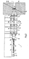
- the Deflection unit 18 which is fixed to the frame of the machine 1 and inside two laterally juxtaposed deflection lines 24a, 24b holds, which converge to reduce the distance between the two filter material strands.
- Each deflection line 24 comprises an inlet funnel 25, into which the strip 13 is conveyed out of the feed 4, and a downstream outlet funnel 26, through which the filter tow line is conveyed to the format line 2.
- the inlet funnel 25 and the outlet funnel 26 each have a nozzle, by means of which a drive gas flow, in particular air flow, is generated to convey the strand.
- the funnels 25, 26 therefore each function as a transport nozzle.
- Each hopper 25 has a straight central axis of symmetry 27, which runs parallel to the conveying direction, or lies in the conveying plane of the strip 13 in the region of the feed 4.
- Each outlet funnel 26 likewise has a rectilinear central axis of symmetry 28, which runs inclined with respect to the conveying direction of the filter material strand out of the inlet funnel 25 and with respect to the conveying direction of the filter material line along the format line 2.
- a tubular deflection part is arranged, in particular a curvature arc 29, which has a curved section for deflecting the conveying direction of the filter material strand from the inlet funnel 25.
- Each arc of curvature 29 is preferably connected directly to the outlet of the inlet funnel 25.
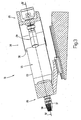
- each hopper 25, 26 comprises a tubular body 30 having a narrowly tapered entrance area (ie, with a gradually decreasing flow channel diameter) and a cylindrical intermediate section (ie with a constant flow channel diameter).
- Each hopper 25, 26 further includes a slightly flared further tubular body 31 (ie, having a gradually increasing flow channel diameter) downstream of the tubular body 30.
- the tubular body 30 is screwed into the further tubular body 31, whereby between an outer surface of the tubular body 30 and an inner surface of the further tubular body 31, a tubular air flow channel 32 is limited, in which a plurality of injection ports 33 open, which are the inner surface of the tubular Break body 30 in the cylindrical intermediate section.
- Supply channels 34 are formed in the further tubular body 31, through which, in operation, compressed air is introduced into the tubular channel 32 and from there through the injection openings 33 into the flow channel of the tubular body 30.
- the injection openings 33 in the inlet funnel 25 are oriented with respect to the central axis of symmetry 27 in such a way that the air flow has an axial component, i. a component parallel to the central axis of symmetry 27, imprinted.
- the injection ports 33 in the feed hopper 25 are oriented with respect to the central axis of symmetry 27 such that both an axial component and a radial component (i.e., perpendicular to the central axis of symmetry 27) are impressed on the airflow.
- the axial air flow component prevails, which serves to press the filter material through the inlet funnel 25, whereas the radial air flow component serves to swirl the air flow.
- the injection openings 33 in the discharge funnel 26 are oriented with respect to the central axis of symmetry 28 such that primarily an axial component (ie parallel to the central axis of symmetry 28) of the air flow is impressed, whereby the feed acting on the filter material is maximized.
- each tubular channel 32 can be adjusted by screwing the tubular body 13 into and out of the further tubular body 31, thereby adjusting the air velocity and flow through the injection openings 33.
- the filter rod material is conveyed between each inlet hopper 25 and outlet hopper 26 through the clearance 35, the filter rod material being exposed, i.e., free, to flow. moved without guide part.
- each hopper 25 may be connected to the corresponding hopper 26 through a perforated tubular expansion member.
- the clearance 35 through which the filter rod material is moved freely, allows expansion of the injected through the injection ports 33 of each inlet funnel 25 compressed air, whereby unwanted backpressure phenomena are avoided. Furthermore, it is thereby made possible for the filter rod material to release excess chemical substances which have been added in the treatment device 17.
- the housing 23 In order to collect and remove the released from the filter rod material chemical substances, the housing 23 is arranged inclined downwards and has at the lowest point a collecting channel, which leads to a catch basin. In order to prevent the chemical substances released from the filter rod material from escaping from the housing 23 and contaminating the rest of the machine 1, the housing 23 is substantially sealed and has only outlet openings arranged in a central region of the housing 23 and against direct spraying are shielded.
- each discharge hopper 26 is provided with a slightly conical perforated tubular body 37 having a plurality of openings 38 and the Outlet funnel 26 is located immediately downstream.
- the passage openings 38 in each perforated tubular body 37 are preferably arranged only on the upper side of the perforated tubular body 37 in order to avoid a downwardly directed air flow, ie an air flow directed onto the format section 2.
- each deflection section 24 of the deflection unit 18 comprises one, two or even more intermediate funnels, which are arranged between the inlet funnel 25 and the outlet funnel 26 and are constructed identically to the funnels 25, 26.
- the machine 1 described above is designed as a single-strand machine and therefore comprises a format part with a format section 2 to form a continuous filter rod 3 and a filter material supply 4.
- the deflection unit or deflection device 18 comprises a deflection path 24 with above
- the machine 1 described above may be formed as a triple or quadruple strand machine and thus a format part with three or four format plug 2 to form three or four continuous filter rods 3 and three or four filter material feeds. 4 include.
- the deflection unit or deflection device 18 has three or four deflection paths 24, which are each equipped with the inlet and outlet funnels 25, 26 described above.
- the filter material obtainable with the deflector 18 described above has excellent homogeneity and, at least in terms of homogeneity, is superior to filter materials made with the deflector currently available on the market.
- the drive roller assemblies 10b, 10c, 10d are different along the feeds 4a, 4b in size and arrangement, but are functionally identical. The following description therefore refers only to one of the drive roller assemblies 10b, 10c, 10d, which is designated by the reference numeral 10 for the sake of simplicity.
- Each drive roller assembly 10 includes, for each feed 4, a drive roller rotated by a motor independent of the motors of the other rollers and a free rotating roller which abuts and engages the drive roller.
- the two motors of the two drive rollers of each drive roller assembly 10 may be located on the same side of the feeders 4 in the machine frame. Alternatively, in each drive roller assembly 10, the motor of a drive roller in the frame of the machine 1 and the motor of the other drive roller may be arranged adjacent to the drive roller.
- the deflection device which is also referred to as a deflection unit 18, described in detail.
- the deflection device essentially comprises a deflection device 50 and a transport device 40, which cooperate with each other such that the deflection of the filter tow rope 13, which is moved by the deflection device, takes place pneumatically.
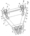
- Fig. 4 illustrated to use a curvature arc 29 which is connected to the pneumatically driven transport nozzles 25, 26.
- Fig. 3 Fig. 4
- the transport nozzles 25a, 25b on the inlet side of the deflecting device 18 are each provided with a curvature arc 29a, 29b.
- curvature arc 29 in the conveying direction above and / or below the respective nozzle, wherein the alternative of arranging the curvature in the conveying direction below the nozzle and thus to pneumatically press the strand through the curvature, leads to better results in terms of Draw resistance and draw resistance spread of the filter material.
- the deflector 50 is adapted to effect a deflection of the filter tow string in a direction comprising at least one horizontal component.
- the deflection is carried out with both a horizontal and a vertical component, since the entire deflection device is arranged inclined with respect to a horizontal plane.
- Diversion generally means that the conveying direction is changed at least once.
- the curvature bends 29 can be replaced by other means, for example by components with an open structure, in particular by a curved baffle plate, which is associated with the pneumatic transport device 40.
- the curved baffle plate can be used to achieve the desired offset of the filter tow string 13 while continuously redirecting the filter tow string.
- the deflection device 50 comprises a deflection part, which is arranged between an inlet funnel or an inlet-transport nozzle and a discharge funnel or a discharge transport nozzle.
- the deflection part may be tubular and comprises a curved section for deflecting the conveying direction of the filter material strand or the sliver coming from the inlet funnel or the inlet transport nozzle.
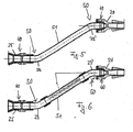
- the deflection device is to be used in a double-strand machine, it is advantageous to change the conveying direction such that the two strands are fed to one another, ie converge ( Fig. 4 ).
- the strands can then be fed to the infeed system of a format part of the machine.
- the device is designed to be even more flexible when the bends 29 are detachably connected to the respective transport nozzle 25, 26, since the device can then be adapted to different process conditions.
- the curvature bends 29 can be arranged to be pivotable, whereby the direction under which the strands leave the respective curvature arc 29 can be changed.
- the curvature arc 29 on the inlet side and the curvature arc 29 on the outlet side of the device can be easily aligned by the respective curvature arcs 29 are pivoted accordingly.
- each curvature arc 29a, 29b oriented on the inlet side of the device such that the central axis of symmetry of the free end of the arc of curvature 29a, 29b, the central axis of symmetry of the remote transport nozzle 26a, 26b on the outlet side of the device in the inlet plane intersects.
- This alignment of the arc of curvature 29a, 29b with respect to the delivery nozzles 26a, 26b on the outlet side of the device provides for uniform transfer of the strand 13 from the respective arc of curvature 29a, 29b to the transport nozzles 26a, 26b.
- the embodiment according to the Figures 3 . 4 relates to a deflection device having a clearance 35 between the curvature arches 29a, 29b and the outlet transport nozzles 26a, 26b.
- a pipe section 51 in particular a straight pipe section 51, which connects a curvature arc 29 on the inlet side of the device and a curvature arc 29 'on the outlet side of the device.
- the two curvature arcs 29, 29 ' are curved in opposite directions, with the central axis of symmetry of the arcs 29, 29' coaxial with the central axis of symmetry of the respective transport nozzle 25, 26 being parallel.
- the ends of the respective curvature arcs 29, 29 ' which are located away from the respective associated transport nozzle 25, 26, are aligned, so that the pipe section 51 can be fitted between the two curvature arcs 29, 29'.
- the pipe section 51 is an extremely effective means for increasing the length of the pipe system. This enhances the turbulence of the filter material that can be achieved with the system and the blooming effect.
- the pipe section 51 does not necessarily have to extend straight. It is also possible to use a pipe section which, at least in sections, has bends or is generally curved.
- a supply device is associated with the pipe section, which allows the feeding of additives, such as activated carbon, plasticizer or other substances into the filter tow line.
- the feeder can be used to feed water into the strand, thereby affecting the cure time.
- a particular advantage of the pipe section 51 is that the length of the system is increased. This makes it possible that the injected additives and / or the injected water is distributed homogeneously over the length of the pipe section in the filter tow line. The quality of the filter rods, which are produced with a machine comprising such a deflection device, can thus be significantly improved.
- the horizontal offset of the deflection device 50 is at least 5 cm.
- a preferred range is 5 - 50 cm, in particular 10 - 40 cm, in particular 15 - 30 cm.
- the total longitudinal length of the device should be at least 200 mm. This means that the axial distance between the inlet side and the outlet side of the device is at least 200 mm.
- Preferred ranges are from 200 to 1000 mm, in particular 500 to 900 mm, in particular 600 to 800 mm.
- the device according to the invention improves the draw resistance as well as the draw resistance spread due to the combined deflection and pneumatic conveying, which leads to an improvement of the turbulence in the system and thus to an increased homogeneity of the filter material.
- the deflection devices described above allow damping of the pulsations that occur at higher processing speeds.
- the damping of the pulsations is due to the increased length of the conveying path, in particular in connection with the use of a pipe section between two associated curves on the inlet and outlet side of the device. In this way, the flowering effect can be improved.
Abstract
Description
Die Erfindung betrifft eine Umlenkvorrichtung zur Förderung und Umlenkung wenigstens eines Filtertowstranges. Diese Vorrichtung kann mit einem Formatteil, insbesondere mit einem Einlaufsystem einer Maschine zur Herstellung von Filterstäben gekoppelt werden. Überdies betrifft die Erfindung eine Maschine umfassend eine derartige Umlenkvorrichtung und ein Verfahren zum Fördern und Umlenken wenigstens eines Filtertowstranges.The invention relates to a deflection device for conveying and deflecting at least one filter tow strand. This device can be coupled with a format part, in particular with an intake system of a machine for the production of filter rods. Moreover, the invention relates to a machine comprising such a deflection device and a method for conveying and deflecting at least one filter tow.
Eine Umlenkvorrichtung der eingangs genannten Art ist beispielsweise aus der
Jede Zuführung ist mit der Formatstrecke durch eine Umlenkeinheit verbunden, die dazu dient, die Streifen in Stränge aus Filtermaterial umzuwandeln und zu stabilisieren. Die Umlenkeinheit erhält einen Streifen von der Zuführung und fördert diesen, in der Form eines gleichmässigen Stranges, auf einen Streifen aus zuvor gummiertem Papier in der Formatstrecke. Die Umlenkeinheit weist üblicherweise für jede Zuführung einen Trichter auf, in den der Streifen eingeführt und verdichtet wird, wodurch der Filtermaterialstrang gebildet wird. Um die Homogenität des Filtermaterials im Strang zu verbessern, kann Luft in den Trichter eingeblasen werden, wie beispielsweise in der
Der Papierstreifen wird in der Formatstrecke transversal um den Strang gewunden, wodurch ein kontinuierlicher Filterstab gebildet wird. Am Auslass der Formatstrecken kontrolliert eine Kontrolleinheit die Dichte der Filterstäbe. Ein Schneidkopf schneidet die Stäbe in einzelne Filterabschnitte.The paper strip is wound in the format section transversally around the strand, whereby a continuous filter rod is formed. At the outlet of the format sections, a control unit controls the density of the filter rods. A cutting head cuts the bars into individual filter sections.
Es ist bekannt, in der Umlenkeinheit den Abstand zwischen den beiden Filtermaterialsträngen zu senken. Zum Beispiel wird in der
Die Verringerung des Abstandes zwischen den beiden Strängen in der Umlenkeinheit der Maschine gemäss der
Filterstäbe, die auf bekannten Filterstabmaschinen mit einer vorstehend beschriebenen Umlenkeinheit hergestellt werden, weisen eine unzureichende Homogenität auf.Filter rods made on known filter rod machines with a deflection unit described above have insufficient homogeneity.
Der Erfindung liegt die Aufgabe zugrunde, die eingangs genannte Umlenkvorrichtung derart weiter zu entwickeln, dass Filterstäbe mit verbesserter Homogenität hergestellt werden können. Überdies soll die Vorrichtung mit vergleichsweise geringen Kosten leicht zu implementieren sein. Eine weitere Aufgabe der Erfindung besteht darin, eine Maschine mit einer derartigen Umlenkvorrichtung sowie ein Verfahren zum Fördern und Umlenken wenigstens eines Filtertowstranges anzugeben.The invention has for its object to further develop the aforementioned deflection such that filter rods can be produced with improved homogeneity. Moreover, the device with comparatively be easy to implement at a low cost. Another object of the invention is to provide a machine with such a deflection device and a method for conveying and deflecting at least one filter tow.
Erfindungsgemäss wird die vorstehend genannte Aufgabe durch eine Maschine zur Herstellung von Zigarettenfiltern nach dem unabhängigen Anspruch 1 gelöst.According to the invention, the above-mentioned object is achieved by a machine for producing cigarette filters according to independent claim 1.
Weitere Verbesserungen und konstruktive Details der Erfindung sind in den Unteransprüchen angegeben.Further improvements and structural details of the invention are specified in the subclaims.
Ein wesentlicher Punkt der Erfindung besteht in der Bereitstellung einer Transporteinrichtung zur pneumatischen Förderung des wenigstens einen Filterstranges sowie einer Umlenkeinrichtung, die mit der Transporteinrichtung zur pneumatisch angetriebenen Umlenkung des Filtertowstranges zusammenwirkt.An essential aspect of the invention is the provision of a transport device for pneumatically conveying the at least one filter strand and a deflection device which cooperates with the transport device for pneumatically driven deflection of the filter tow strand.
Dies bedeutet, dass die Förderrichtung des Stranges geändert wird, wobei die Antriebskraft, wenigstens in dem Bereich, wo die Förderrichtung geändert wird, also im Bereich der Umlenkung pneumatisch aufgebracht wird.This means that the conveying direction of the strand is changed, wherein the driving force, at least in the region where the conveying direction is changed, that is pneumatically applied in the region of the deflection.
Ohne sich an die folgende Theorie zu binden, wird angenommen, dass die Kombination des pneumatischen Transportes mit der Umlenkung des Stranges in einer verstärkten Verwirbelung des Materiales resultiert, wodurch ein sehr homogenes Filtermaterial erhalten wird. Insbesondere sind der Zugwiderstand sowie die Zugwiderstandstreuung eines Filterstabes signifikant verbessert, der durch eine Filterstrangmaschine mit der erfindungsgemässen Umlenkvorrichtung erhältlich ist. Überdies kann die erfindungsgemässe Umlenkvorrichtung kostengünstig realisiert werden, so dass die Gesamtkosten der Filterstrangmaschine verringert werden. Die erfindungsgemässe Umlenkvorrichtung kann auf einfache Weise in bekannten Filterstrangmaschinen verwendet werden, wobei lediglich die bestehende Umlenkeinheit einer derartigen Maschine durch die erfindungsgemäße Umlenkvorrichtung ersetzt wird.Without wishing to be bound by the theory that follows, it is believed that the combination of pneumatic transport with strand deflection results in increased fluidization of the material, resulting in a very homogeneous filter material. In particular, the draw resistance and draw resistance spread of a filter rod are significantly improved, which is obtainable by a filter rod machine with the inventive deflection device. Moreover, the deflection device according to the invention can be realized cost-effectively, so that the total cost of the filter rod machine can be reduced. The inventive deflection device can be used in a simple manner in known filter rod machines, wherein only the existing deflection unit of such a machine is replaced by the deflection device according to the invention.
Im Gegensatz zu der erfindungsgemäßen Umlenkvorrichtung ist die bekannte Umlenkvorrichtung gemäß
Die Umlenkvorrichtung gemäß
In einer bevorzugten Ausführungsform ist die Umlenkeinrichtung derart angepasst, dass die Umlenkung des wenigstens einen Filtertowstranges wenigstens eine horizontale Komponente aufweist. Es hat sich gezeigt, dass aufgrund der horizontalen Komponente der Umlenkung der Zugwiderstand und die Zugwiderstandstreuung weiter verbessert werden können. Im Gegensatz dazu sieht die Umlenkvorrichtung gemäß
Die Transporteinrichtung kann wenigstens eine pneumatisch betriebene Transportdüse aufweisen, wodurch eine besonders einfache technische Umsetzung der Transporteinrichtung erzielt wird, da herkömmliche Transportdüsen verwendet werden können.The transport device may have at least one pneumatically operated transport nozzle, whereby a particularly simple technical implementation the transport device is achieved since conventional transport nozzles can be used.
Vorzugsweise weist die Transporteinrichtung zwei Transportdüsen auf, die im Bereich der Einlassseite und der Auslassseite der Vorrichtung angeordnet sind. Der Einsatz zweier Transportdüsen, von denen eine Düse der anderen Düse nachgeordnet ist, verbessert die Flexibilität des Herstellungsprozesses. Beispielsweise können die beiden Düsen mit unterschiedlichen Drücken betrieben werden, um die Eigenschaften des Filtertowstranges zu beeinflussen.Preferably, the transport device has two transport nozzles, which are arranged in the region of the inlet side and the outlet side of the device. The use of two transport nozzles, one nozzle of which is arranged downstream of the other nozzle, improves the flexibility of the manufacturing process. For example, the two nozzles can be operated at different pressures to influence the properties of the filter tow.
In einer weiteren Ausgestaltung der Erfindung umfasst die Umlenkeinrichtung wenigstens einen Krümmungsbogen, der zumindest abschnittsweise den Förderweg des Filtertowstranges bestimmt. Der Einsatz eines Krümmungsbogens im Zusammenhang mit der Umlenkeinrichtung hat den Vorteil, dass eine kontinuierliche Umlenkung des Filtertowstranges erreicht wird.In a further embodiment of the invention, the deflection device comprises at least one curvature arc which determines the conveying path of the filter tow strand at least in sections. The use of a curvature arc in connection with the deflection device has the advantage that a continuous deflection of the filter tow strand is achieved.
Generell gilt, dass jede Komponente mit einem kontinuierlich gekrümmten Aufbau, der eine Ablenkung eines Luftstromes bewirkt, wie beispielsweise ein Prallblech, geeignet ist, um die Umlenkeinrichtung zu implementieren.In general, any component having a continuously curved configuration that causes a deflection of an airflow, such as a baffle, is suitable for implementing the baffle.
Der Krümmungsbogen kann mit der an der Auslassseite vorgesehenen Transportdüse und/oder mit der an der Einlassseite vorgesehenen Transportdüse verbunden, insbesondere lösbar verbunden sein. Auf diese Weise wirken der Krümmungsbogen und die Transportdüse unmittelbar zusammen, wodurch sichergestellt wird, dass die Umlenkung pneumatisch angetrieben wird bzw. pneumatisch erfolgt. Aufgrund der lösbaren Verbindung zwischen dem Krümmungsbogen und der Transportdüse kann jeweils eine der beiden Transportdüsen mit einem Krümmungsbogen oder beide Transportdüsen jeweils mit einem Krümmungsbogen ausgestattet sein.The curvature arc can be connected to the transport nozzle provided on the outlet side and / or with the transport nozzle provided on the inlet side, in particular detachably connected. In this way, the curvature arc and the transport nozzle act together directly, which ensures that the deflection is driven pneumatically or pneumatically. Due to the detachable connection between the curvature arc and the transport nozzle, in each case one of the two transport nozzles can be equipped with a curvature arc or both transport nozzles each with a curvature arc.
Um die Position des Krümmungsbogens bzw. der Vielzahl der Krümmungsbögen entweder im Hinblick auf die Transportdüse oder im Hinblick auf einen gegenüber angeordneten Krümmungsbogen einzustellen, kann vorgesehen sein, dass der Krümmungsbogen bzw. die Vielzahl der Krümmungsbögen drehbar bzw. schwenkbar angeordnet sind.To adjust the position of the arc of curvature or the plurality of curvature arcs either with respect to the transport nozzle or with respect to an oppositely disposed arc of curvature can be provided be that the curvature arc or the plurality of curvature arcs are arranged rotatably or pivotally.
Die Untergrenze des Krümmungswinkels des Krümmungsbogens kann wenigstens 10° betragen, wobei bevorzugte Bereiche zwischen 10° - 80°, 20° - 60° und 30° - 50° liegen.The lower limit of the curvature angle of the curvature arc may be at least 10 °, with preferred ranges between 10 ° - 80 °, 20 ° - 60 ° and 30 ° - 50 °.
Eine gleichmäßige Überführung des Filtertowstranges von einem Krümmungsbogen zu dem zugeordneten weiteren Krümmungsbogen kann dadurch erreicht werden, dass die von der jeweiligen Transportdüse entfernten Enden der Krümmungsbögen fluchtend angeordnet sind.A uniform transfer of the filter tow strand from a curve of curvature to the associated further curve of curvature can be achieved by the fact that the ends of the curved bends remote from the respective transport nozzle are aligned.
In einer weiteren bevorzugten Ausführungsform ist vorgesehen, dass die Krümmungsbögen durch einen Rohrabschnitt, insbesondere einen geradlinig ausgebildeten Rohrabschnitt verbunden sind. Diese Ausführungsform ist insbesondere unter Sicherheitsgründen als bevorzugt anzusehen, da dabei vermieden wird, dass ein schnell laufender, ungeschützter Filtertowstrang für Betriebspersonal zugänglich ist.In a further preferred embodiment it is provided that the curvature arches are connected by a pipe section, in particular a rectilinear pipe section. This embodiment is to be regarded as preferred in particular for safety reasons, as it is avoided that a fast-running, unprotected filter tow line is accessible to operating personnel.
Überdies stellt der Rohrabschnitt ein wirksames Mittel dar, die Länge der Umlenkvorrichtung zu vergrößern, was zu dem positiven Effekt führt, dass Pulsationen gedämpft werden, die insbesondere bei hohen Verarbeitungsgeschwindigkeiten kritisch werden. Erhöhte Pulsationen stehen im Zusammenhang mit den an der Einlaufdüse aufgebrachten höheren Drücken, die erforderlich sind, um eine ordnungsgemäße Einspeisung des Stranges in den Finger zu gewährleisten. Aufgrund der kurzen Führungskanäle bei herkömmlichen Umlenksystemen werden derartige Pulsationen fast ungedämpft auf das Formatteil der Maschine übertragen. Dies führt zu einer erhöhten Streuung des Zugwiderstandes, insbesondere bei hohen Verarbeitungsgeschwindigkeiten. Außerdem verstärkt die vergrößerte Länge des Systems gemäß dieser Ausführungsform der Erfindung den Blüheffekt (blooming effect).Moreover, the tube section is an effective means of increasing the length of the diverter, resulting in the positive effect of dampening pulsations, which become critical particularly at high processing speeds. Increased pulsations are related to the higher pressures applied to the inlet nozzle, which are necessary to ensure proper feeding of the strand into the finger. Due to the short guide channels in conventional deflection systems such pulsations are transmitted almost undamped on the format part of the machine. This leads to an increased scattering of the draw resistance, especially at high processing speeds. In addition, the increased length of the system according to this embodiment of the invention enhances the blooming effect.
Der Rohrabschnitt kann zumindest abschnittsweise perforiert sein, wodurch das Austreten von Druckluft aus dem Rohrabschnitt ermöglicht wird.The pipe section may be perforated at least in sections, whereby the escape of compressed air from the pipe section is made possible.
In einer weiteren bevorzugten Ausführungsform der Erfindung ist der Rohrabschnitt mit einer Zufuhreinrichtung zur Einspeisung von Zusatzstoffen, wie Aktivkohle, Weichmacher und/oder zur Einspeisung von Wasser versehen. Aufgrund der vergrößerten Länge des Systems führt die Einspeisung von Additiven und/oder Wasser im Rohrabschnitt zu einer homogenen Verteilung der Additive und/oder des Wassers im Filtertowstrang. Überdies gewährleistet die Einspeisung von Wasser im Rohrabschnitt der Umlenkvorrichtung' eine sichere Trennung der Wasserzufuhr vom Triacetinkreislauf, der wasserfrei sein muss, um eine Hydrolyse des Triacetins zu vermeiden.In a further preferred embodiment of the invention, the pipe section is provided with a feed device for feeding in additives, such as activated carbon, plasticizer and / or for feeding water. Due to the increased length of the system, the feed of additives and / or water in the pipe section leads to a homogeneous distribution of the additives and / or the water in the filter tow line. Moreover, the feeding of water in the pipe section of the deflector ensures a safe separation of the water supply from the triacetin, which must be anhydrous to prevent hydrolysis of the triacetin.
In einer anderen Ausführungsform ist ein Freiraum zwischen den Krümmungsbögen ausgebildet, wodurch die Freisetzung chemischer Substanzen aus dem Filtertowstrang ermöglicht wird, die dem Strang zugegeben wurden, bevor dieser in die Umlenkvorrichtung eingeführt wird.In another embodiment, a clearance is formed between the arcs of curvature, thereby enabling the release of chemical substances from the filter tow strand that have been added to the strand before it is introduced into the diverter.
Vorzugsweise ist die Umlenkeinrichtung für einen horizontalen Versatz des wenigstens einen Filtertowstranges von mindestens 5 cm, insbesondere von 5 - 50 cm, insbesondere von 10 - 40 cm, insbesondere von 15 - 30 cm angepasst. Eine geeignete Länge der Vorrichtung, um eine gute Verwirbelung des Filterstrangmateriales zu erzielen, wird erreicht, wenn die longitudinale Gesamtlänge der Vorrichtung mindestens 200 mm, insbesondere 200 - 1000 mm, insbesondere 500 - 900 mm, insbesondere 600 - 800 mm beträgt.Preferably, the deflecting device is adapted for a horizontal offset of the at least one filter tow strand of at least 5 cm, in particular from 5 to 50 cm, in particular from 10 to 40 cm, in particular from 15 to 30 cm. A suitable length of the device in order to achieve a good turbulence of the filter rod material is achieved if the total longitudinal length of the device is at least 200 mm, in particular 200-1000 mm, in particular 500-900 mm, in particular 600-800 mm.
Die Erfindung wird nachstehend unter Bezug auf die in den beigefügten Zeichnungen schematisch dargestellten Ausführungsbeispiele näher erläutert. In diesen zeigen:
- Fig. 1
- eine schematische Seitenansicht eines bevorzugten Ausführungs- beispiels einer Doppelstrangfilterstabmaschine gemäß der Erfin- dung;
- Fig. 2
- eine Draufsicht der Maschine gemäß
Fig. 1 ; eine Seitenansicht im Teilschnitt der Umlenkeinheit bzw. Umlenkvorrichtung der Maschine gemässFig. 1 , wobei aus Gründen der Klarheit Teile weggelassen wurden; - Fig. 4
- einen Schnitt entlang der Linie IV-IV der Umlenkeinheit bzw. Umlenkvorrichtung gemäss
Fig. 3 ; - Fig. 5
- einen Querschnitt durch ein weiteres Ausführungsbeispiel der erfindungsgemässen Umlenkvorrichtung umfassend einen Rohrabschnitt;
- Fig. 6
- einen Querschnitt durch ein weiteres Ausführungsbeispiel der erfindungsgemässen Umlenkvorrichtung, wobei der Rohrabschnitt perforiert ist; und
- Fig. 7
- ein weiteres Ausführungsbeispiel der erfindungsgemässen Umlenkvorrichtung, das für eine Doppelstrangmaschine angepasst ist.
- Fig. 1
- a schematic side view of a preferred embodiment of a double-stranded filter rod machine according to the invention;
- Fig. 2
- a plan view of the machine according to
Fig. 1 ; a side view in partial section of the deflection or deflection of the machine according toFig. 1 with parts omitted for the sake of clarity; - Fig. 4
- a section along the line IV-IV of the deflection or deflection device according to
Fig. 3 ; - Fig. 5
- a cross section through a further embodiment of the inventive deflection device comprising a pipe section;
- Fig. 6
- a cross section through a further embodiment of the inventive deflecting device, wherein the pipe section is perforated; and
- Fig. 7
- a further embodiment of the inventive deflection device, which is adapted for a double-strand machine.
Bezugszeichen 1 in
Wie in den
Die Förderstrecke 5 umfasst eine Doppelführungseinrichtung 11, die oberhalb der Ballen 8a, 8b zur Führung der Lunten 9a, 9b angeordnet ist. Die Förderstrecke 5 umfasst ferner eine Saugeinrichtung 12, die unmittelbar in Förderrichtung vor der Führungsanordnung 10a an der Einlaufstation 6 angeordnet ist, um die Lunten 9a, 9b in transversaler Richtung in jeweilige abschnittsweise flache Streifen 13a, 13b auseinander zu ziehen, die der Führungseinrichtung 10a zugeführt werden. Nach der Führungseinrichtung 10a werden die beiden Streifen 13a, 13b entlang der Zuführungen bzw. Zuführstrecken 4a, 4b in im Wesentlichen horizontaler Richtung 14 durch eine Presseinrichtung 15 gefördert, die eine Führungsrollen- bzw. Bremsrollenanordnung 10a sowie zwei Antriebsrollenanordnungen 10b, 10c umfasst. Die beiden Streifen 13a, 13b werden daraufhin entlang der jeweiligen Zuführungen 4a, 4b in Richtung 14 durch eine Expansionseinrichtung 16 gefördert, die Luft in die Streifen 13a, 13b einbläst, um deren Volumen zu erhöhen. Daraufhin werden die Streifen 13a, 13b durch eine Aufbereitungseinrichtung 17 transportiert, wo chemische Substanzen, insbesondere Triacetin, den Streifen 13a, 13b zugegeben werden, so dass dem Filtermaterial Formbarkeit und/oder Aroma verliehen wird. Schliesslich werden die beiden Streifen 13a, 13b entlang der jeweiligen Zuführungen 4a, 4b in Richtung 14 durch eine Antriebsrollenanordnung 10d gefördert, die ähnlich wie die Anordnungen 10b, 10c aufgebaut ist und einen Auslaufbereich der Zuführungen 4a, 4b bzw. Zuführstrecken 4a, 4b definiert.The
Die Zuführungen 4a, 4b sind mit den Formatstrecken 2a, 2b des Formatteiles durch eine Umlenkeinheit bzw. Umlenkvorrichtung 18 verbunden, die der Rollenanordnung 10d unmittelbar nachgeordnet ist. Die Umlenkeinheit 18 erhält die Streifen 13a, 13b aus den Zuführungen 4a, 4b, sammelt die Streifen 13a, 13b gleichmässig zur Bildung von zwei Strängen aus Filtermaterial und fördert die Filtermaterialstränge zu den Formatstrecken 2a, 2b. In den beiden Formatstrecken 2a, 2b wird jeder Filtermaterialstrang auf einen Papierstreifen 19a, 19b gefördert, der zuvor in einer Gummierstation 20 gummiert wurde und daraufhin transversal um den Filtermaterialstrang zur Bildung eines kontinuierlichen Filterstabes 3a, 3b gewickelt wird.The
Am Ausgang der Formatstrecken 2a, 2b kontrollieren eine oder mehrere Kontrollstationen 21 verschiedene Qualitätseigenschaften der Filterstäbe 3a, 3b (beispielsweise Dichte, Durchmesser, Erscheinungsbild...). Ein Schneidkopf 22 schneidet die Stäbe 3a, 3b transversal in jeweils nachfolgende Filterabschnitte (nicht gezeigt). Wie in den
Jede Umlenkstrecke 24 umfasst einen Einlauftrichter 25, in den der Streifen 13 aus der Zuführung 4 gefördert wird, sowie einen nachgeordneten Auslauftrichter 26, durch den der Filtertowstrang zur Formatstrecke 2 gefördert wird. Der Einlauftrichter 25 und der Auslauftrichter 26 weisen jeweils eine Düse auf, mit deren Hilfe ein Antriebs-Gasstrom, insbesondere Luftstrom, zur Förderung des Stranges erzeugt wird. Die Trichter 25, 26 fungieren daher jeweils als Transportdüse. Jeder Trichter 25 weist eine gerade zentrale Symmetrieachse 27 auf, die parallel zur Förderrichtung verläuft, bzw. in der Förderebene des Streifens 13 im Bereich der Zuführung 4 liegt. Jeder Auslauftrichter 26 weist ebenfalls eine geradlinige zentrale Symmetrieachse 28 auf, die bezüglich der Förderrichtung des Filtermaterialstranges aus dem Einlauftrichter 25 sowie bezüglich der Förderrichtung des Filtermaterialstranges entlang der Formatstrecke 2 geneigt verläuft. Zwischen dem jeweiligen Einlauftrichter 25 und Auslauftrichter 26 ist ein rohrförmiges Umlenkteil angeordnet, insbesondere ein Krümmungsbogen 29, der einen gekrümmten Abschnitt zur Umlenkung der Förderrichtung des Filtermaterialstranges aus dem Einlauftrichter 25 aufweist. Jeder Krümmungsbogen 29 ist vorzugsweise direkt mit dem Ausgang des Einlauftrichters 25 verbunden.Each
Zur weiteren Verbesserung der Homogenität des Filtermaterials im Filtermaterialstrang wird Luft in jeden Trichter 25, 26 eingeblasen. Konkret umfasst jeder Trichter 25, 26 einen rohrförmigen Körper 30 mit einem sich eng verjüngenden Eingangsbereich (d.h. mit einem allmählich abnehmenden Strömungskanaldurchmesser) und einem zylindrischen Zwischenabschnitt (d.h. mit einem konstanten Strömungskanaldurchmesser). Jeder Trichter 25, 26 umfasst ferner einen sich leicht aufweitenden weiteren rohrförmigen Körper 31 (d.h. mit einem allmählich zunehmenden Strömungskanaldurchmesser), der dem rohrförmigen Körper 30 nachgeordnet ist.To further improve the homogeneity of the filter material in the filter material strand, air is injected into each
Der rohrförmige Körper 30 ist in den weiteren rohrförmigen Körper 31 eingeschraubt, wodurch zwischen einer Außenfläche des rohrförmigen Körpers 30 und einer Innenfläche des weiteren rohrförmigen Körpers 31 ein rohrförmiger Luftströmungskanal 32 begrenzt ist, in den eine Mehrzahl von Einblasöffnungen 33 münden, die die Innenfläche des rohrförmigen Körpers 30 im zylindrischen Zwischenabschnitt durchbrechen. Zufuhrkanäle 34 sind in dem weiteren rohrförmigen Körper 31 gebildet, durch die, im Betrieb, Druckluft in den rohrförmigen Kanal 32 und von dort durch die Einblasöffnungen 33 in den Strömungskanal des rohrförmigen Körpers 30 eingebracht wird.The
Die Einblasöffnungen 33 im Einlauftrichter 25 sind, bezogen auf die zentrale Symmetrieachse 27, so orientiert, dass dem Luftstrom eine axiale Komponente, d.h. eine Komponente parallel zur zentralen Symmetrieachse 27, aufgeprägt wird.The
In einer Abwandlung sind die Einblasöffnungen 33 im Einlauftrichter 25 bezüglich der zentralen Symmetrieachse 27 derart orientiert, dass dem Luftstrom sowohl eine axiale Komponente als auch eine radiale Komponente (d.h. senkrecht zur zentralen Symmetrieachse 27) aufgeprägt wird. Dabei herrscht die axiale Luftströmungskomponente vor, die dazu dient, das Filtermaterial durch den Einlauftrichter 25 zu pressen, wohingegen die radiale Luftströmungskomponente dazu dient, die Luftströmung zu verwirbeln.In a modification, the
Die Einblasöffnungen 33 im Auslauftrichter 26 sind bezüglich der zentralen Symmetrieachse 28 derart orientiert, dass primär eine axiale Komponente (d.h. parallel zur zentralen Symmetrieachse 28) der Luftströmung aufgeprägt wird, wodurch der auf das Filtermaterial wirkende Vorschub maximiert wird.The
Bei der Montage und Justierung der Umlenkeinheit 18 kann der Luftströmungsbereich jedes rohrförmigen Kanals 32 dadurch eingestellt werden, dass der rohrförmige Körper 13 in den weiteren rohrförmigen Körper 31 hinein- bzw. herausgeschraubt wird, wodurch die Luftgeschwindigkeit und -strömung durch die Einblasöffnungen 33 eingestellt werden.During assembly and adjustment of the
Ferner sei angemerkt, dass das Filterstrangmaterial zwischen jedem Einlauftrichter 25 und Auslauftrichter 26 durch den Freiraum 35 gefördert wird, wobei das Filterstrangmaterial sich frei, d.h. ohne Führungsteil bewegt.It should also be noted that the filter rod material is conveyed between each
In Abwandlung der in den
Der Freiraum 35, durch den das Filterstrangmaterial frei bewegt wird, ermöglicht eine Expansion der durch die Einblasöffnungen 33 jedes Einlauftrichters 25 eingeblasenen Druckluft, wodurch unerwünschte Gegendruck-Phänomene vermieden werden. Ferner wird dadurch ermöglicht, dass das Filterstrangmaterial überschüssige chemische Substanzen freisetzt, die in der Aufbereitungseinrichtung 17 zugegeben wurden. Um die aus dem Filterstrangmaterial freigesetzten chemischen Substanzen zu sammeln und abzuführen, ist das Gehäuse 23 nach unten geneigt angeordnet und weist am tiefsten Punkt einen Auffangkanal auf, der zu einem Auffangbecken führt. Um zu vermeiden, dass die aus dem Filterstrangmaterial freigesetzten chemischen Substanzen aus dem Gehäuse 23 entweichen und die übrige Maschine 1 kontaminieren, ist das Gehäuse 23 im Wesentlichen abgedichtet und weist lediglich Auslassöffnungen auf, die in einem mittleren Bereich des Gehäuses 23 angeordnet und gegen direkte Besprühung abgeschirmt sind.The
Um eine freie Expansion der durch die Einblasöffnungen 33 in jeden Auslauftrichter 26 eingeblasenen Druckluft zu ermöglichen (und somit ungewünschte Gegendruck-Phänomene zu vermeiden), ist jeder Auslauftrichter 26 mit einem leicht konischen, perforierten rohrförmigen Körper 37 versehen, der eine Mehrzahl von Öffnungen 38 aufweist und dem Auslauftrichter 26 unmittelbar nachgeordnet ist. Die Durchgangsöffnungen 38 in jedem perforierten rohrförmigen Körper 37 sind vorzugsweise nur auf der Oberseite des perforierten rohrförmigen Körpers 37 angeordnet, um eine nach unten gerichtete Luftströmung, d.h. eine auf die Formatstrecke 2 gerichtete Luftströmung zu vermeiden.In order to allow free expansion of the compressed air injected through the
In einem nicht dargestellten alternativen Ausführungsbeispiel umfasst jede Umlenkstrecke 24 der Umlenkeinheit 18 einen, zwei oder noch mehr Zwischentrichter, die zwischen dem Einlauftrichter 25 und dem Auslauftrichter 26 angeordnet und identisch wie die Trichter 25, 26 aufgebaut sind.In an alternative embodiment, not shown, each
In einem weiteren nicht dargestellten Ausführungsbeispiel ist die vorstehend beschriebene Maschine 1 als Einzelstrangsmaschine ausgebildet und umfasst daher ein Formatteil mit einer Formatstrecke 2 zur Bildung eines kontinuierlichen Filterstabes 3 und eine Filtermaterialzuführung 4. In diesem Fall umfasst die Umlenkeinheit bzw. Umlenkvorrichtung 18 eine Umlenkstrecke 24 mit vorstehend beschriebenen Einlauf- und Auslauftrichtern 25, 26. In ähnlicher Weise kann die vorstehend beschriebene Maschine 1 als Dreifach- oder Vierfachstrangmaschine ausgebildet sein und somit ein Formatteil mit drei oder vier Formatstecken 2 zur Bildung von drei oder vier kontinuierlichen Filterstäben 3 sowie drei oder vier Filtermaterialzuführungen 4 umfassen. In diesem Fall weist die Umlenkeinheit bzw. Umlenkvorrichtung 18 drei oder vier Umlenkstrecken 24 auf, die jeweils mit den vorstehend beschriebenen Einlauf- und Auslauftrichter 25, 26 ausgestattet sind.In another embodiment, not shown, the machine 1 described above is designed as a single-strand machine and therefore comprises a format part with a format section 2 to form a continuous filter rod 3 and a filter material supply 4. In this case, the deflection unit or
Das mit der vorstehend beschriebenen Umlenkeinheit bzw. Umlenkvorrichtung 18 herstellbare Filtermaterial weist eine hervorragende Homogenität auf und ist, zumindest im Hinblick auf die Homogenität, Filtermaterialien überlegen, die mit gegenwärtig auf dem Markt erhältlichen Umlenkeinheit hergestellt werden.The filter material obtainable with the
Die Antriebsrollenanordnungen 10b, 10c, 10d unterscheiden sich entlang der Zuführungen 4a, 4b in Grösse und Anordnung, sind aber funktional identisch. Die nachfolgende Beschreibung bezieht sich daher nur auf eine der Antriebsrollenanordnungen 10b, 10c, 10d, die der Einfachheit halber mit dem Bezugszeichen 10 bezeichnet wird. Jede Antriebsrollenanordnung 10 umfasst für jede Zuführung 4 eine Antriebsrolle, die durch einen Motor unabhängig von den Motoren der anderen Rollen gedreht wird, sowie eine frei drehende Rolle, die an der Antriebsrolle anliegt und mit dieser zusammmenwirkt. Die beiden Motoren der beiden Antriebsrollen jeder Antriebsrollenanordnung 10 können auf der selben Seite der Zuführungen 4 im Maschinenrahmen angeordnet sein. Alternativ kann bei jeder Antriebsrollenanordnung 10 der Motor einer Antriebsrolle im Rahmen der Maschine 1 und der Motor der anderen Antriebsrolle neben der Antriebsrolle angeordnet sein.The
Nachfolgend wird die Umlenkvorrichtung, die auch als Umlenkeinheit 18 bezeichnet wird, näher beschrieben.Hereinafter, the deflection device, which is also referred to as a
Wie in den
Es bestehen verschiedene Möglichkeiten, die Umlenkvorrichtung technisch zu realisieren. Beispielsweise ist es möglich, wie in den
Es ist auch möglich, nur die Transportdüsen 26a, 26b auf der Auslassseite der Umlenkvorrichtung jeweils mit einem Krümmungsbogen zu versehen (nicht dargestellt). Eine weitere Option besteht darin, sowohl die Transportdüsen 26 auf der Auslassseite als auch die Transportdüsen 25 auf der Einlassseite der Umlenkvorrichtung mit jeweiligen Krümmungsbögen 29 auszustatten (
Generell ist es möglich, den Krümmungsbogen entweder der zugehörigen Transportdüse in Förderrichtung nachzuordnen, wie in
Ferner ist möglich, den Krümmungsbogen 29 in Förderrichtung oberhalb und/oder unterhalb der jeweiligen Düse anzuordnen, wobei die Alternative, den Krümmungsbogen in Förderrichtung unterhalb der Düse anzuordnen und damit den Strang pneumatisch durch den Krümmungsbogen zu pressen, zu besseren Ergebnissen führt im Hinblick auf den Zugwiderstand und die Zugwiderstandstreuung des Filtermaterials.It is also possible to arrange the
In
Umlenkung bedeutet dabei allgemein, dass die Förderrichtung wenigstens einmal geändert wird.Diversion generally means that the conveying direction is changed at least once.
Zur technischen Realisierung der Umlenkeinrichtung 50 können die Krümmungsbögen 29 durch andere Mittel ersetzt werden, beispielsweise durch Komponenten mit einem offenen Aufbau, insbesondere durch eine gekrümmte Prallplatte, die der pneumatischen Transporteinrichtung 40 zugeordnet ist. Die gekrümmte Prallplatte kann eingesetzt werden, um den gewünschten Off-set des Filtertowstranges 13 zu erzielen und gleichzeitig den Filtertowstrang kontinuierlich umzulenken.For the technical realization of the
Generell können Komponenten zur technischen Umsetzung der Umlenkeinrichtung 50 verwendet werden, die eine kontinuierliche und pneumatisch angetriebene Umlenkung des Filtertowstranges ermöglichen. Dies bedeutet, dass die Umlenkeinrichtung 50 wenigstens eine kontinuierlich gekrümmte Wand aufweisen sollte, die wenigstens abschnittsweise den Führungsweg des Filtertowstranges begrenzt und gleichzeitig die Förderrichtung ändert. Allgemein umfasst die Umlenkeinrichtung 50 ein Umlenkteil, das zwischen einem Einlauftrichter oder einer Einlauf-Transportdüse und einem Auslauftrichter oder einer Auslauf-Transportdüse angeordnet ist. Das Umlenkteil kann rohrförmig ausgebildet sein und umfasst einen gekrümmten Abschnitt zur Umlenkung der Förderrichtung des Filtermaterialstranges bzw. der Lunte, die aus dem Einlauftrichter oder der Einlauf-Transportdüse kommt.In general, components for the technical implementation of the
Wenn die Umlenkvorrichtung in einer Doppelstrangmaschine eingesetzt werden soll, ist es vorteilhaft, die Förderrichtung so zu ändern, dass die beiden Stränge aufeinander zugeführt werden, d.h. konvergieren (
Die Vorrichtung wird noch flexibler gestaltet, wenn die Krümmungsbögen 29 lösbar mit der jeweiligen Transportdüse 25, 26 verbunden sind, da die Vorrichtung dann an unterschiedliche Prozessbedingungen angepasst werden kann. Überdies können die Krümmungsbögen 29 schwenkbar bzw. drehbar angeordnet sein, wodurch die Richtung, unter der die Stränge den jeweiligen Krümmungsbogen 29 verlassen, verändert werden kann. Der Krümmungsbogen 29 auf der Einlassseite und der Krümmungsbogen 29 auf der Auslassseite der Vorrichtung können einfach ausgerichtet werden, indem die jeweiligen Krümmungsbögen 29 entsprechend verschwenkt werden.The device is designed to be even more flexible when the
Wie in
Das Ausführungsbeispiel gemäß den
Der Rohrabschnitt 51 stellt ein äußerst wirksames Mittel dar, um die Länge des Rohrsystems zu vergrößern. Dadurch werden die mit dem System erzielbare Verwirbelung des Filtermaterials und der Blüheffekt (blooming effect) verstärkt. Der Rohrabschnitt 51 muss sich nicht notwendigerweise gerade erstrecken. Es ist auch möglich, einen Rohrabschnitt einzusetzen, der, wenigstens abschnittsweise, Krümmungsbögen aufweist bzw. allgemein gekrümmt ist.The
Wie in
In einer weiteren bevorzugten Ausführungsform der Erfindung, die in den Figuren nicht dargestellt ist, ist eine Zufuhreinrichtung dem Rohrabschnitt zugeordnet, die die Einspeisung von Additiven, wie beispielsweise Aktivkohle, Weichmacher oder anderen Substanzen in den Filtertowstrang ermöglicht. Überdies kann die Zufuhreinrichtung dazu verwendet werden, um Wasser in den Strang einzuspeisen, wodurch die Aushärtezeit beeinflusst wird. Ein besonderer Vorteil des Rohrabschnittes 51 besteht darin, dass die Länge des Systems vergrößert wird. Dadurch wird es möglich, dass die eingespeisten Additive und/oder das eingespeiste Wasser sich homogen über die Länge des Rohrabschnittes im Filtertowstrang verteilt. Die Qualität der Filterstäbe, die mit einer Maschine umfassend eine solche Umlenkvorrichtung hergestellt werden, kann somit signifikant verbessert werden.In a further preferred embodiment of the invention, which is not shown in the figures, a supply device is associated with the pipe section, which allows the feeding of additives, such as activated carbon, plasticizer or other substances into the filter tow line. Moreover, the feeder can be used to feed water into the strand, thereby affecting the cure time. A particular advantage of the
Im Hinblick auf die Dimension der Umlenkvorrichtung ist es vorteilhaft, dass der horizontale Versatz der Umlenkeinrichtung 50 wenigstens 5 cm beträgt. Ein bevorzugter Bereich beträgt 5 - 50 cm, insbesondere 10 - 40 cm, insbesondere 15 - 30 cm. Die longitudinale Gesamtlänge der Vorrichtung sollte wenigstens 200 mm betragen. Dies bedeutet, dass der axiale Abstand zwischen der Einlassseite und der Auslassseite der Vorrichtung wenigstens 200 mm beträgt. Bevorzugte Bereiche liegen von 200 - 1000 mm, insbesondere 500 - 900 mm, insbesondere 600 - 800 mm.With regard to the dimension of the deflection device, it is advantageous that the horizontal offset of the
Der Krümmungswinkel jedes Krümmungsbogens beträgt wenigstens 10°. Der Krümmungswinkel ist dabei der spitze Winkel zwischen den beiden zentralen Symmetrieachsen eines Krümmungsbogens. Der Krümmungswinkel in
Die vorstehend beschriebene Umlenkvorrichtung kann sowohl für eine Einzelstrang- als auch für eine Doppelstrangmaschine verwendet werden, wobei die für die Einzelstrangmaschine vorgesehenen Ausführungsbeispiele in den
Die Rohrsysteme gemäß den
Zusammenfassen verbessert die erfindungsgemäße Vorrichtung den Zugwiderstand sowie die Zugwiderstandstreuung aufgrund der kombinierten Umlenkung und pneumatischen Förderung, die zu einer Verbesserung der Verwirbelung im System und somit zu einer erhöhten Homogenität des Filtermaterials führt.To summarize, the device according to the invention improves the draw resistance as well as the draw resistance spread due to the combined deflection and pneumatic conveying, which leads to an improvement of the turbulence in the system and thus to an increased homogeneity of the filter material.
Überdies erlauben die vorstehend beschriebenen Umlenkvorrichtungen eine Dämpfung der Pulsationen, die bei höheren Verarbeitungsgeschwindigkeiten auftreten. Die Dämpfung der Pulsationen erfolgt aufgrund der vergrößerten Länge des Förderweges, insbesondere im Zusammenhang mit der Verwendung eines Rohrabschnittes zwischen zwei zugeordneten Krümmungsbögen auf der Einlass- und Auslassseite der Vorrichtung. Auf diese Weise kann auch der Blüheffekt verbessert werden.Moreover, the deflection devices described above allow damping of the pulsations that occur at higher processing speeds. The damping of the pulsations is due to the increased length of the conveying path, in particular in connection with the use of a pipe section between two associated curves on the inlet and outlet side of the device. In this way, the flowering effect can be improved.
- 11
- Maschinemachine
- 2a, 2b2a, 2b
- Formatstreckenformat routes
- 3a, 3b3a, 3b
- Filterstäbefilter rods
- 4a, 4b4a, 4b
- Zuführungenadditions
- 55
- Förderstreckeconveyor line
- 66
- Einlaufstationinfeed station
- 77
- Vorratsbereichstorage area
- 8a, 8b8a, 8b
- Ballenbale
- 9a, 9b9a, 9b
- Luntefuse
- 10a10a
- FührungsrollenanordnungGuide roller assembly
- 10b, 10c10b, 10c
- AntriebsrollenanordnungDrive roller assembly
- 10d10d
- Rollenanordnungroller assembly
- 1111
- DoppelführungseinrichtungDouble guide device
- 1212
- Saugeinrichtungsuction
- 13a, 13b13a, 13b
- Strangstrand
- 1414
- horizontale Richtunghorizontal direction
- 1515
- Presseinrichtungpresser
- 1616
- Expansionseinrichtungexpander
- 1717
- Aufbereitungseinrichtungconditioning device
- 1818
- Umlenkeinheit bzw. UmlenkvorrichtungDeflection unit or deflection device
- 19a, 19b19a, 19b
- Streifen aus gummiertem PapierStrip of rubberized paper
- 2020
- Gummierstationgumming
- 2121
- Kontrollstationcontrol station
- 2222
- Schneidkopfcutting head
- 2323
- Gehäusecasing
- 24a, 24b24a, 24b
- Umlenkstreckendeflecting sections
- 25, 2625, 26
- Transportdüsentransport jets
- 27,2827.28
- Symmetrieachsenaxes of symmetry
- 2929
- Krümmungsbogencurvature arch
- 3030
- rohrförmiger Körpertubular body
- 3131
- weiterer rohrförmiger Körperanother tubular body
- 3232
- Luftkanalair duct
- 3333
- Einblasöffnungeninjection openings
- 3434
- Zufuhrkanälesupply channels
- 3535
- Freiraumfree space
- 3636
- Auslassöffnungenoutlet
- 3737
- perforierter rohrförmiger Körperperforated tubular body
- 4040
- Transporteinrichtungtransport means
- 5050
- Umlenkeinrichtungdeflecting
- 5151
- Rohrabschnittpipe section
Claims (19)
- A cigarette filter manufacturing machine (1); the machine (1) comprising:a number of feed lines (4) for respective continuous strips (13) of filtering material;a number of forming beams (2) for forming respective continuous filter rods (3); anda twisting assembly (18) which is located between the feed lines (4) and the forming beams (2), receives the strips (13) from the feed lines (4), gathers the strips (13) uniformly into two ropes of filtering material, and feeds the ropes of filtering material to the forming beams (2);wherein the twisting assembly (18) comprises a number of twisting lines (24), each of which comprises an input funnel (25) into which the strip (13) from the feed line (4) is fed;characterized in that each twisting line (24) of the twisting assembly (18) comprises an output funnel (26) which is separated and located downstream from the input funnel (25), and through which a rope of filtering material is fed to the forming beam (2).
- A machine (1) as claimed in Claim 1, wherein the twisting lines (24) of the twisting assembly (18) are side by side and converge to reduce the distance between the ropes of filtering material.
- A machine (1) as claimed in Claim 1 or 2, wherein each input funnel (25) has a central axis (27) of symmetry which is straight and parallel to the feed direction/lies in the feed plane of the strip (13) from the feed line (4).
- A machine (1) as claimed in Claim 1, 2 or 3, wherein, between each input funnel (25) and the output funnel (26), there is interposed a diverting member (29), which is tubular and comprises a curved portion for diverting the feed direction of the rope of filtering material from the input funnel (25).
- A machine (1) as claimed in Claim 4, wherein each diverting member (29) is fitted directly to the outlet of the input funnel (25).
- A machine (1) as claimed in one of Claims 1 to 5, wherein each output funnel (26) has a central axis (28) of symmetry, which is straight and inclined slightly with respect to the feed direction of the rope of filtering material from the input funnel (25), and with respect to the feed direction of the rope of filtering material along the forming beam (2).
- A machine (1) as claimed in one of Claims 1 to 6, wherein air is blown into each funnel (25, 26) through blow holes (33) which debouch inside the funnel (25, 26).
- A machine (1) as claimed in Claim 7, wherein each funnel (25, 26) comprises a first tubular body (30), and a second tubular body (31) downstream from the first tubular body (30); the first tubular body (30) is screwed inside the second tubular body (31) to define, between an outer surface of the first tubular body (30) and an inner surface of the second tubular body (31), a tubular airflow channel (32) which debouches inside the blow holes (33).
- A machine (1) as claimed in Claim 8, wherein the first tubular body (30) comprises a narrowly tapering initial portion and a cylindrical intermediate portion; and the second tubular body (31) flares slightly.
- A machine (1) as claimed in Claim 8 or 9, wherein the blow holes (33) of each input funnel (25) are oriented with respect to the central axis (27) of symmetry to impart both an axial component and a radial component to the airflow.
- A machine (1) as claimed in Claim 8 or 9, wherein the blow holes (33) of each input funnel (25) are oriented with respect to the central axis (27) of symmetry to only impart an axial component to the airflow.
- A machine (1) as claimed in one of Claims 8 to 11, wherein the blow holes (33) of each output funnel (26) are oriented with respect to the central axis (28) of symmetry to only impart an axial component to the airflow.
- A machine (1) as claimed in one of Claims 1 to 12, wherein, between each input funnel (25) and the output funnel (26), the rope of filtering material is fed through a clear area (35), in which the rope of filtering material travels freely with no guiding members.
- A machine (1) as claimed in Claim 13, wherein the twisting assembly (18) comprises a box body (23) internally supporting the twisting lines (24).
- A machine (1) as claimed in Claim 14, wherein, to collect and drain off the chemical substances released by the ropes of filtering material, the box body (23) is tilted downwards, and comprises, at the lowest point, a catch channel which drains into a catch tank.
- A machine (1) as claimed in Claim 14 or 15, wherein the box body (23) is substantially sealed, and comprises compressed-air relief openings (36) shielded against direct spray.
- A machine (1) as claimed in one of Claims 1 to 16, wherein each output funnel (26) is fitted with a perforated tubular body (37) having a number of through holes (38) and located immediately downstream from the output funnel (26).
- A machine (1) as claimed in Claim 17, wherein the through holes (38) in each perforated tubular body (37) are only formed in the top of the perforated tubular body (37) to prevent airflow being directed onto the forming beam (2).
- A machine (1) as claimed in one of Claims 1 to 18, wherein each twisting line (24) of the twisting assembly (18) comprises at least one intermediate funnel located between the input funnel (25) and the output funnel (26).
Applications Claiming Priority (2)
| Application Number | Priority Date | Filing Date | Title |
|---|---|---|---|
| DE200610001643 DE102006001643A1 (en) | 2006-01-12 | 2006-01-12 | Deflection device for conveying and deflection of filter tow strand, has passage and returning device, which cooperates with transport unit for pneumatically driven deflection of filter tow strand |
| PCT/EP2006/011042 WO2007087848A2 (en) | 2006-01-12 | 2006-11-15 | Deflecting device for a continuous filter tow, method for conveying and deflecting at least one continuous filter tow, and device for the production of cigarette filters |
Publications (2)
| Publication Number | Publication Date |
|---|---|
| EP1978833A2 EP1978833A2 (en) | 2008-10-15 |
| EP1978833B1 true EP1978833B1 (en) | 2011-01-19 |
Family
ID=37461573
Family Applications (1)
| Application Number | Title | Priority Date | Filing Date |
|---|---|---|---|
| EP06818621A Active EP1978833B1 (en) | 2006-01-12 | 2006-11-15 | Deflecting device for a continuous filter tow, method for conveying and deflecting at least one continuous filter tow, and device for the production of cigarette filters |
Country Status (5)
| Country | Link |
|---|---|
| EP (1) | EP1978833B1 (en) |
| JP (1) | JP2009523015A (en) |
| CN (1) | CN101394760B (en) |
| DE (2) | DE102006001643A1 (en) |
| WO (1) | WO2007087848A2 (en) |
Cited By (1)
| Publication number | Priority date | Publication date | Assignee | Title |
|---|---|---|---|---|
| EP3231298B1 (en) | 2009-04-21 | 2020-05-20 | Hauni Maschinenbau GmbH | Capsule position regulation in filters for the tobacco processing industry |
Families Citing this family (11)
| Publication number | Priority date | Publication date | Assignee | Title |
|---|---|---|---|---|
| DE102007057396A1 (en) | 2007-11-27 | 2009-05-28 | Hauni Maschinenbau Ag | Device for processing at least two filter tows |
| DE102008003368A1 (en) * | 2008-01-08 | 2009-07-09 | Hauni Maschinenbau Aktiengesellschaft | Device for transporting a filter tow |
| DE102008016827A1 (en) * | 2008-04-01 | 2009-10-08 | Hauni Maschinenbau Ag | Device for transporting a filter tow |
| DE102008024553A1 (en) | 2008-05-21 | 2009-12-03 | Hauni Maschinenbau Aktiengesellschaft | Device for introducing additives into a strand provided for the production of a smoking article and already round-shaped |
| DE102008057457A1 (en) * | 2008-11-14 | 2010-05-20 | Hauni Maschinenbau Aktiengesellschaft | Device for transporting a filter tow strip |
| DE102009022790A1 (en) | 2009-05-27 | 2010-12-02 | Hauni Maschinenbau Aktiengesellschaft | Apparatus for processing filter bowl line in tobacco processing industry, has filter bowl guide path, along which filter bowl line is guided in transport direction |
| IT1395043B1 (en) | 2009-08-18 | 2012-09-05 | Gd Spa | METHOD AND MACHINE FOR THE CONTEMPORARY PRODUCTION OF AT LEAST TWO FILTER BUGS FOR CIGARETTES. |
| IT1408375B1 (en) * | 2010-10-20 | 2014-06-20 | Gd Spa | UNIT AND METHOD OF FEEDING ELEMENTS OF ADDITIVES OF FIBER MATERIAL IN A MACHINE FOR THE PRODUCTION OF SMOKE ITEMS |
| ITBO20100637A1 (en) * | 2010-10-22 | 2012-04-23 | Gd Spa | MACHINE FOR THE PRODUCTION OF FILTERS FOR CIGARETTES. |
| ITBO20110206A1 (en) * | 2011-04-18 | 2012-10-19 | Gd Spa | COMPACT GROUP FOR A MACHINE FOR THE PRODUCTION OF FILTERS FOR CIGARETTES. |
| ITBO20130314A1 (en) | 2013-06-21 | 2014-12-22 | Gd Spa | MACHINE FOR THE PRODUCTION OF FILTERS FOR CIGARETTES |
Family Cites Families (13)
| Publication number | Priority date | Publication date | Assignee | Title |
|---|---|---|---|---|
| US4511420A (en) * | 1980-12-16 | 1985-04-16 | Molins, Ltd. | Continuous rod manufacture |
| GB2089190B (en) * | 1980-12-16 | 1985-05-30 | Molins Ltd | Quality control in continuous rod manufacture |
| US4522616A (en) * | 1982-03-10 | 1985-06-11 | Celanese Corporation | Method and apparatus for forming cigarette filter rods |
| US4541825A (en) * | 1982-12-27 | 1985-09-17 | Celanese Corporation | Low air pressure method and apparatus for forming filter rods |
| IT1185472B (en) | 1984-11-10 | 1987-11-12 | Hauni Werke Koerber & Co Kg | PROCEDURE AND DEVICE FOR PRODUCING STICKS-FILTER |
| DE3640883A1 (en) | 1986-11-29 | 1988-06-09 | Rhodia Ag | METHOD AND DEVICES FOR MANUFACTURING TOBACCO Fume Filter Rods |
| JP2965184B2 (en) * | 1991-12-09 | 1999-10-18 | 三菱レイヨン株式会社 | Air jet |
| DE4300841A1 (en) * | 1992-01-16 | 1993-07-22 | Molins Plc | |
| US5331976A (en) * | 1992-10-21 | 1994-07-26 | Hoechst Celanese Corporation | Transport jet adapter |
| DE10200320A1 (en) * | 2002-01-07 | 2003-07-17 | Hauni Maschinenbau Ag | Method and device for producing a fiber strand of the tobacco processing industry |
| CN2642061Y (en) * | 2003-04-16 | 2004-09-22 | 云南烟草科学研究院 | Device for feeding liquid and linear materials in acetate silk |
| WO2005009151A1 (en) * | 2003-07-25 | 2005-02-03 | Mitsubishi Rayon Co., Ltd. | Manufacturing apparatus for plug of cigarttte filter and manufacturing method for the filter |
| DE10354924B4 (en) * | 2003-11-25 | 2024-01-18 | Körber Technologies Gmbh | Device for processing filter tow material and device for producing filters |
-
2006
- 2006-01-12 DE DE200610001643 patent/DE102006001643A1/en not_active Ceased
- 2006-11-15 DE DE502006008784T patent/DE502006008784D1/en active Active
- 2006-11-15 JP JP2008549773A patent/JP2009523015A/en active Pending
- 2006-11-15 EP EP06818621A patent/EP1978833B1/en active Active
- 2006-11-15 CN CN200680053609.9A patent/CN101394760B/en not_active Expired - Fee Related
- 2006-11-15 WO PCT/EP2006/011042 patent/WO2007087848A2/en active Application Filing
Cited By (1)
| Publication number | Priority date | Publication date | Assignee | Title |
|---|---|---|---|---|
| EP3231298B1 (en) | 2009-04-21 | 2020-05-20 | Hauni Maschinenbau GmbH | Capsule position regulation in filters for the tobacco processing industry |
Also Published As
| Publication number | Publication date |
|---|---|
| CN101394760A (en) | 2009-03-25 |
| WO2007087848A3 (en) | 2007-10-25 |
| JP2009523015A (en) | 2009-06-18 |
| DE102006001643A1 (en) | 2007-07-26 |
| EP1978833A2 (en) | 2008-10-15 |
| CN101394760B (en) | 2011-09-28 |
| WO2007087848A2 (en) | 2007-08-09 |
| DE502006008784D1 (en) | 2011-03-03 |
Similar Documents
| Publication | Publication Date | Title |
|---|---|---|
| EP1978833B1 (en) | Deflecting device for a continuous filter tow, method for conveying and deflecting at least one continuous filter tow, and device for the production of cigarette filters | |
| EP2292107B1 (en) | Device for providing filter tow material and device for producing filters | |
| EP1847186B1 (en) | Processing unit for processing at least one strip of filter tow for manufacturing filters for rod-shaped tobacco articles | |
| EP0919144B2 (en) | Method and device for treating a stream of filter tow | |
| EP1847187B1 (en) | Processing unit for processing at least one filter strip and device with at least two such processing units | |
| DE102007006674A1 (en) | Air spinning device | |
| WO2013117493A1 (en) | Air spinning machine with separate spinning and piecing nozzles | |
| EP2123180A1 (en) | Device for inserting additives into a previously rounded line for the manufacture of tobacco products | |
| EP3165635A1 (en) | Stretching device | |
| DE202012003924U1 (en) | Compactor or compactor group for a machine for the production of cigarette filters | |
| DE102012204443A1 (en) | A fiber processing apparatus of the tobacco processing industry and a process for the preparation of finite fibers for producing a fiber strand of the tobacco processing industry | |
| EP1692957A1 (en) | Treating a strip of filter material in the tobacco industry | |
| EP1490539B1 (en) | Pneumatic compaction device for a fiber assembly and method for pneumatically compacting a fiber assembly | |
| EP3165636A1 (en) | Stretching device | |
| DE1710017A1 (en) | Method and device for spinning yarn | |
| DE10321283A1 (en) | Textile fleece making assembly has variable-speed compressed air supply to a jet directed at rotating drum | |
| DE102006006504A1 (en) | Stretching method and drafting system for refining fiber material | |
| DE102009022790A1 (en) | Apparatus for processing filter bowl line in tobacco processing industry, has filter bowl guide path, along which filter bowl line is guided in transport direction | |
| EP1654407B1 (en) | Nonwoven guiding device for a textile machine, and associated textile machine | |
| EP2982253A1 (en) | Transporting nozzle for a device for the production of filter rods for the tobacco industry and device for production of filter rods for the tobacco industry | |
| DE102006006505B4 (en) | Method and device for compacting band-shaped fibrous material | |
| WO2007025535A2 (en) | Drafting system for fabricating fibrous material | |
| DE202014010449U1 (en) | Cigarette filter manufacturing machine | |
| DE102009021808B4 (en) | Deflection device for filter tow | |
| DE10352152A1 (en) | Process and assembly to manufacture cigarette filter fibers that area combination of cellulose ester and cellulose |
Legal Events
| Date | Code | Title | Description |
|---|---|---|---|
| PUAI | Public reference made under article 153(3) epc to a published international application that has entered the european phase |
Free format text: ORIGINAL CODE: 0009012 |
|
| 17P | Request for examination filed |
Effective date: 20080731 |
|
| AK | Designated contracting states |
Kind code of ref document: A2 Designated state(s): CH DE GB LI NL |
|
| RBV | Designated contracting states (corrected) |
Designated state(s): CH DE GB LI NL |
|
| GRAP | Despatch of communication of intention to grant a patent |
Free format text: ORIGINAL CODE: EPIDOSNIGR1 |
|
| TPAC | Observations filed by third parties |
Free format text: ORIGINAL CODE: EPIDOSNTIPA |
|
| DAX | Request for extension of the european patent (deleted) | ||
| GRAS | Grant fee paid |
Free format text: ORIGINAL CODE: EPIDOSNIGR3 |
|
| GRAA | (expected) grant |
Free format text: ORIGINAL CODE: 0009210 |
|
| AK | Designated contracting states |
Kind code of ref document: B1 Designated state(s): CH DE GB LI NL |
|
| REG | Reference to a national code |
Ref country code: GB Ref legal event code: FG4D Free format text: NOT ENGLISH |
|
| REG | Reference to a national code |
Ref country code: CH Ref legal event code: EP |
|
| REG | Reference to a national code |
Ref country code: CH Ref legal event code: NV Representative=s name: HEPP WENGER RYFFEL AG |
|
| REF | Corresponds to: |
Ref document number: 502006008784 Country of ref document: DE Date of ref document: 20110303 Kind code of ref document: P |
|
| REG | Reference to a national code |
Ref country code: DE Ref legal event code: R096 Ref document number: 502006008784 Country of ref document: DE Effective date: 20110303 |
|
| REG | Reference to a national code |
Ref country code: NL Ref legal event code: T3 |
|
| PLBE | No opposition filed within time limit |
Free format text: ORIGINAL CODE: 0009261 |
|
| STAA | Information on the status of an ep patent application or granted ep patent |
Free format text: STATUS: NO OPPOSITION FILED WITHIN TIME LIMIT |
|
| 26N | No opposition filed |
Effective date: 20111020 |
|
| REG | Reference to a national code |
Ref country code: DE Ref legal event code: R097 Ref document number: 502006008784 Country of ref document: DE Effective date: 20111020 |
|
| REG | Reference to a national code |
Ref country code: NL Ref legal event code: V1 Effective date: 20120601 |
|
| REG | Reference to a national code |
Ref country code: CH Ref legal event code: PL |
|
| PG25 | Lapsed in a contracting state [announced via postgrant information from national office to epo] |
Ref country code: CH Free format text: LAPSE BECAUSE OF NON-PAYMENT OF DUE FEES Effective date: 20111130 Ref country code: NL Free format text: LAPSE BECAUSE OF NON-PAYMENT OF DUE FEES Effective date: 20120601 Ref country code: LI Free format text: LAPSE BECAUSE OF NON-PAYMENT OF DUE FEES Effective date: 20111130 |
|
| PGFP | Annual fee paid to national office [announced via postgrant information from national office to epo] |
Ref country code: GB Payment date: 20121126 Year of fee payment: 7 |
|
| GBPC | Gb: european patent ceased through non-payment of renewal fee |
Effective date: 20131115 |
|
| PG25 | Lapsed in a contracting state [announced via postgrant information from national office to epo] |
Ref country code: GB Free format text: LAPSE BECAUSE OF NON-PAYMENT OF DUE FEES Effective date: 20131115 |
|
| PGFP | Annual fee paid to national office [announced via postgrant information from national office to epo] |
Ref country code: DE Payment date: 20231129 Year of fee payment: 18 |