JP2009502526A - Longitudinal cutting device for continuous longitudinally proceeding material width part for forming outer band with variable length direction - Google Patents
Longitudinal cutting device for continuous longitudinally proceeding material width part for forming outer band with variable length direction Download PDFInfo
- Publication number
- JP2009502526A JP2009502526A JP2008523405A JP2008523405A JP2009502526A JP 2009502526 A JP2009502526 A JP 2009502526A JP 2008523405 A JP2008523405 A JP 2008523405A JP 2008523405 A JP2008523405 A JP 2008523405A JP 2009502526 A JP2009502526 A JP 2009502526A
- Authority
- JP
- Japan
- Prior art keywords
- cutting
- cutting device
- cutting tool
- drive mechanism
- axis
- Prior art date
- Legal status (The legal status is an assumption and is not a legal conclusion. Google has not performed a legal analysis and makes no representation as to the accuracy of the status listed.)
- Pending
Links
Images


Classifications
-
- B—PERFORMING OPERATIONS; TRANSPORTING
- B26—HAND CUTTING TOOLS; CUTTING; SEVERING
- B26D—CUTTING; DETAILS COMMON TO MACHINES FOR PERFORATING, PUNCHING, CUTTING-OUT, STAMPING-OUT OR SEVERING
- B26D3/00—Cutting work characterised by the nature of the cut made; Apparatus therefor
- B26D3/10—Making cuts of other than simple rectilinear form
-
- B—PERFORMING OPERATIONS; TRANSPORTING
- B26—HAND CUTTING TOOLS; CUTTING; SEVERING
- B26D—CUTTING; DETAILS COMMON TO MACHINES FOR PERFORATING, PUNCHING, CUTTING-OUT, STAMPING-OUT OR SEVERING
- B26D1/00—Cutting through work characterised by the nature or movement of the cutting member or particular materials not otherwise provided for; Apparatus or machines therefor; Cutting members therefor
- B26D1/01—Cutting through work characterised by the nature or movement of the cutting member or particular materials not otherwise provided for; Apparatus or machines therefor; Cutting members therefor involving a cutting member which does not travel with the work
- B26D1/12—Cutting through work characterised by the nature or movement of the cutting member or particular materials not otherwise provided for; Apparatus or machines therefor; Cutting members therefor involving a cutting member which does not travel with the work having a cutting member moving about an axis
- B26D1/14—Cutting through work characterised by the nature or movement of the cutting member or particular materials not otherwise provided for; Apparatus or machines therefor; Cutting members therefor involving a cutting member which does not travel with the work having a cutting member moving about an axis with a circular cutting member, e.g. disc cutter
- B26D1/157—Cutting through work characterised by the nature or movement of the cutting member or particular materials not otherwise provided for; Apparatus or machines therefor; Cutting members therefor involving a cutting member which does not travel with the work having a cutting member moving about an axis with a circular cutting member, e.g. disc cutter rotating about a movable axis
- B26D1/18—Cutting through work characterised by the nature or movement of the cutting member or particular materials not otherwise provided for; Apparatus or machines therefor; Cutting members therefor involving a cutting member which does not travel with the work having a cutting member moving about an axis with a circular cutting member, e.g. disc cutter rotating about a movable axis mounted on a movable carriage
- B26D1/185—Cutting through work characterised by the nature or movement of the cutting member or particular materials not otherwise provided for; Apparatus or machines therefor; Cutting members therefor involving a cutting member which does not travel with the work having a cutting member moving about an axis with a circular cutting member, e.g. disc cutter rotating about a movable axis mounted on a movable carriage for thin material, e.g. for sheets, strips or the like
-
- B—PERFORMING OPERATIONS; TRANSPORTING
- B26—HAND CUTTING TOOLS; CUTTING; SEVERING
- B26D—CUTTING; DETAILS COMMON TO MACHINES FOR PERFORATING, PUNCHING, CUTTING-OUT, STAMPING-OUT OR SEVERING
- B26D1/00—Cutting through work characterised by the nature or movement of the cutting member or particular materials not otherwise provided for; Apparatus or machines therefor; Cutting members therefor
- B26D1/01—Cutting through work characterised by the nature or movement of the cutting member or particular materials not otherwise provided for; Apparatus or machines therefor; Cutting members therefor involving a cutting member which does not travel with the work
- B26D1/12—Cutting through work characterised by the nature or movement of the cutting member or particular materials not otherwise provided for; Apparatus or machines therefor; Cutting members therefor involving a cutting member which does not travel with the work having a cutting member moving about an axis
- B26D1/14—Cutting through work characterised by the nature or movement of the cutting member or particular materials not otherwise provided for; Apparatus or machines therefor; Cutting members therefor involving a cutting member which does not travel with the work having a cutting member moving about an axis with a circular cutting member, e.g. disc cutter
- B26D1/22—Cutting through work characterised by the nature or movement of the cutting member or particular materials not otherwise provided for; Apparatus or machines therefor; Cutting members therefor involving a cutting member which does not travel with the work having a cutting member moving about an axis with a circular cutting member, e.g. disc cutter coacting with a movable member, e.g. a roller
- B26D1/225—Cutting through work characterised by the nature or movement of the cutting member or particular materials not otherwise provided for; Apparatus or machines therefor; Cutting members therefor involving a cutting member which does not travel with the work having a cutting member moving about an axis with a circular cutting member, e.g. disc cutter coacting with a movable member, e.g. a roller for thin material, e.g. for sheets, strips or the like
-
- B—PERFORMING OPERATIONS; TRANSPORTING
- B26—HAND CUTTING TOOLS; CUTTING; SEVERING
- B26D—CUTTING; DETAILS COMMON TO MACHINES FOR PERFORATING, PUNCHING, CUTTING-OUT, STAMPING-OUT OR SEVERING
- B26D5/00—Arrangements for operating and controlling machines or devices for cutting, cutting-out, stamping-out, punching, perforating, or severing by means other than cutting
- B26D5/20—Arrangements for operating and controlling machines or devices for cutting, cutting-out, stamping-out, punching, perforating, or severing by means other than cutting with interrelated action between the cutting member and work feed
-
- B—PERFORMING OPERATIONS; TRANSPORTING
- B26—HAND CUTTING TOOLS; CUTTING; SEVERING
- B26D—CUTTING; DETAILS COMMON TO MACHINES FOR PERFORATING, PUNCHING, CUTTING-OUT, STAMPING-OUT OR SEVERING
- B26D7/00—Details of apparatus for cutting, cutting-out, stamping-out, punching, perforating, or severing by means other than cutting
- B26D7/26—Means for mounting or adjusting the cutting member; Means for adjusting the stroke of the cutting member
- B26D7/2628—Means for adjusting the position of the cutting member
- B26D7/2635—Means for adjusting the position of the cutting member for circular cutters
-
- B—PERFORMING OPERATIONS; TRANSPORTING
- B26—HAND CUTTING TOOLS; CUTTING; SEVERING
- B26F—PERFORATING; PUNCHING; CUTTING-OUT; STAMPING-OUT; SEVERING BY MEANS OTHER THAN CUTTING
- B26F1/00—Perforating; Punching; Cutting-out; Stamping-out; Apparatus therefor
- B26F1/38—Cutting-out; Stamping-out
- B26F1/3806—Cutting-out; Stamping-out wherein relative movements of tool head and work during cutting have a component tangential to the work surface
- B26F1/3813—Cutting-out; Stamping-out wherein relative movements of tool head and work during cutting have a component tangential to the work surface wherein the tool head is moved in a plane parallel to the work in a coordinate system fixed with respect to the work
- B26F1/3826—Cutting-out; Stamping-out wherein relative movements of tool head and work during cutting have a component tangential to the work surface wherein the tool head is moved in a plane parallel to the work in a coordinate system fixed with respect to the work using a rotary circular cutting member
-
- Y—GENERAL TAGGING OF NEW TECHNOLOGICAL DEVELOPMENTS; GENERAL TAGGING OF CROSS-SECTIONAL TECHNOLOGIES SPANNING OVER SEVERAL SECTIONS OF THE IPC; TECHNICAL SUBJECTS COVERED BY FORMER USPC CROSS-REFERENCE ART COLLECTIONS [XRACs] AND DIGESTS
- Y10—TECHNICAL SUBJECTS COVERED BY FORMER USPC
- Y10T—TECHNICAL SUBJECTS COVERED BY FORMER US CLASSIFICATION
- Y10T83/00—Cutting
- Y10T83/202—With product handling means
- Y10T83/2066—By fluid current
- Y10T83/207—By suction means
-
- Y—GENERAL TAGGING OF NEW TECHNOLOGICAL DEVELOPMENTS; GENERAL TAGGING OF CROSS-SECTIONAL TECHNOLOGIES SPANNING OVER SEVERAL SECTIONS OF THE IPC; TECHNICAL SUBJECTS COVERED BY FORMER USPC CROSS-REFERENCE ART COLLECTIONS [XRACs] AND DIGESTS
- Y10—TECHNICAL SUBJECTS COVERED BY FORMER USPC
- Y10T—TECHNICAL SUBJECTS COVERED BY FORMER US CLASSIFICATION
- Y10T83/00—Cutting
- Y10T83/647—With means to convey work relative to tool station
- Y10T83/6584—Cut made parallel to direction of and during work movement
- Y10T83/6587—Including plural, laterally spaced tools
-
- Y—GENERAL TAGGING OF NEW TECHNOLOGICAL DEVELOPMENTS; GENERAL TAGGING OF CROSS-SECTIONAL TECHNOLOGIES SPANNING OVER SEVERAL SECTIONS OF THE IPC; TECHNICAL SUBJECTS COVERED BY FORMER USPC CROSS-REFERENCE ART COLLECTIONS [XRACs] AND DIGESTS
- Y10—TECHNICAL SUBJECTS COVERED BY FORMER USPC
- Y10T—TECHNICAL SUBJECTS COVERED BY FORMER US CLASSIFICATION
- Y10T83/00—Cutting
- Y10T83/647—With means to convey work relative to tool station
- Y10T83/6584—Cut made parallel to direction of and during work movement
- Y10T83/6592—Interrelated work-conveying and tool-moving means
- Y10T83/6595—With means to move tool laterally of feed direction during cutting
Abstract
本発明は、単純で、経済的で、その実施が簡単であると同時に、高速生産に応じることの可能である装置である予め決められかつ制御されるランダムな順番で変動する長さ方向外形の連続縦方向進行材料幅部内の切断を可能にする切断装置に関する。本発明による切断装置(5)には材料幅部の縦進行方向Dに垂直に配置される対向筒(71)と協働する円状刃(61)が含まれる1組の切断工具(60)が含まれる。これらの切断工具(60)は台座(50)に関する2軸、各切断工具の切断角度を修正するよう対向する筒(71)に垂直な回転軸(A)ならびに2つの切断工具(60)間の間隔を修正するように対向筒(71)に平行な平行移動軸(B)により移動可能に取り付けられる。各切断工具(60)は変動しかつ与えられたランダムな順番で外形の切断線に応じて中央制御装置により2軸(A,B)による組み合わせで制御される回転駆動機構(8)と平行移動機構(90)に連結される。用途:文房具、織物、プラスチックフィルム等の分野、特に郵便物処理機の分野
【選択図】図3The present invention is simple, economical, simple to implement and at the same time a device capable of responding to high-speed production with a longitudinal profile that varies in a predetermined and controlled random order. The present invention relates to a cutting device that enables cutting in a continuous longitudinally proceeding material width. The cutting device (5) according to the present invention includes a set of cutting tools (60) including a circular blade (61) cooperating with an opposing cylinder (71) arranged perpendicular to the longitudinal direction D of the material width. Is included. These cutting tools (60) have two axes with respect to the pedestal (50), a rotation axis (A) perpendicular to the opposite cylinder (71) to correct the cutting angle of each cutting tool, and between the two cutting tools (60). It is movably attached by a parallel movement axis (B) parallel to the opposing cylinder (71) so as to correct the interval. Each cutting tool (60) fluctuates and translates in parallel with the rotary drive mechanism (8) controlled by a combination of two axes (A, B) by the central controller according to the cutting line of the outer shape in a given random order Connected to mechanism (90). Application: Stationery, textiles, plastic film, etc., especially mail processing machines [selection figure] Fig. 3
Description
本発明は、ランダムな順番で長さ方向変動する外形に従って少なくとも1本の帯を切断するための連続縦方向進行材料、特に紙あるいは同様のものの幅部の長さ方向切断装置に関するもので、この装置には材料幅部の縦進行方向に垂直に配置される少なくとも1つの対向部品と協働する少なくとも1つの第1組の切断工具、ならびに対向部品に平行な平行移動軸により2つの切断工具の間の間隔が修正されるようにかつ対向部品に垂直な回転軸により切断角度が修正されるように、移動する前記切断工具が取り付けられる少なくとも1つの台座が含まれる。 The present invention relates to a continuous longitudinally proceeding material for cutting at least one strip according to a profile that varies in the longitudinal direction in a random order, in particular to a longitudinal cutting device for the width of paper or the like. The apparatus comprises at least one first set of cutting tools cooperating with at least one opposing part arranged perpendicular to the longitudinal direction of the material width, and two cutting tools by means of a translation axis parallel to the opposing part. At least one pedestal on which the moving cutting tool is mounted is included so that the spacing between them is modified and the cutting angle is modified by a rotation axis perpendicular to the opposing part.
連続縦方向進行幅部の切断装置は文房具の分野、例えば、封筒や封筒に導入されるよう仕向けられる文書の切断装置が見受けられる郵便物が準備されるために採用される機械ではよく知られている。あらゆる場合において、紙の同一幅部に切断する文書は一様であり切断の形状とピッチは一定である。切断工具は、従って、連続縦方向進行する紙幅部内で、回転筒がなす少なくとも1つの外形または各回転時の形状の切断を可能にする回転筒上に取り付けられる切断刃で形成され、この外形あるいはこの形状は一様にかつ周期的に再現される。このタイプの切断工具では再現可能な順番では記録されないランダムに変動する外形または形状の切断は可能とならない。 Cutting devices for continuous longitudinal width are well known in the field of stationery, for example, machines used to prepare envelopes and postal items that can be found in document cutting devices intended to be introduced into envelopes. Yes. In all cases, the document cut into the same width of the paper is uniform and the cutting shape and pitch are constant. The cutting tool is thus formed with a cutting blade mounted on a rotating cylinder that allows cutting of at least one outer shape or the shape of each rotation within the paper width part that proceeds continuously in the longitudinal direction. This shape is reproduced uniformly and periodically. This type of cutting tool does not allow cutting of randomly varying contours or shapes that are not recorded in a reproducible order.
公開GB-702 116には紙幅部の各端部に設置されると同時に、非線形の切断外形による紙の幅縁部の切断のためにそれぞれ横方向に移動しやすく揺動アーム端部に取り付けられる2つの尖端またはルーレットが含まれる別の切断装置が説明されている。切断工具の横移動は揺動アームに連結されると同時に回転筒内に設置されるカム外形内に誘導される駆動指により得られる。この装置により得られる切断外形も周期的であり、切断工具の行程は筒の各回転につき一様である。 Open GB-702 116 is installed at each end of the paper width part, and at the same time, it is attached to the end of the swing arm for easy movement in the lateral direction for cutting the width edge of the paper with a non-linear cutting profile Another cutting device is described that includes two tips or roulette. The lateral movement of the cutting tool is obtained by a driving finger that is connected to the swing arm and is guided in the outer shape of the cam installed in the rotating cylinder. The cutting profile obtained with this device is also periodic and the stroke of the cutting tool is uniform for each rotation of the cylinder.
公開US 5,918,519ではまた、横方向移動キャリッジに乗せられると同時に、この切断点により刃の横移動時に円弧が描かれると同時にランダムな非線形の切断外形が生ずるように、刃の切断地点から遠ざかる垂直軸廻りを動くバランス棒により支持される対向部品と協働する2つの円形刃が含まれる別の切断装置も説明されている。刃が横方向に移動する時にのみ生ずる条件での刃の角度移動は、故に、制御可能ではない。このため得られる切断外形は制御されない。 In the published US 5,918,519, a vertical axis that moves away from the cutting point of the blade so that it can be placed on a laterally moving carriage and at the same time a circular arc is drawn by the cutting point and at the same time a random non-linear cutting profile is generated. Another cutting device is also described that includes two circular blades that cooperate with opposing parts supported by a balance rod that moves about. The angular movement of the blade under conditions that only occur when the blade moves laterally is therefore not controllable. For this reason, the cutting outline obtained is not controlled.
従って、既知の切断装置はランダムで完全に制御された順番の長さ方向外形に応じた切断は不可能な点で満足がいくものではない。
本発明は、単純で経済的、実施と構成が容易で、高速生産に応えることの可能な装置である連続した縦方向に進行する材料の幅部に、ランダムな順番で変動する制御された長さ方向外形の切断を可能にする切断装置を提案してこれらの不都合をなくすことにある。 The present invention is a simple, economical, easy to implement and configure device that is capable of responding to high speed production, with a controlled length that varies in a random order in the width of a continuous longitudinally proceeding material. The purpose of this invention is to eliminate these disadvantages by proposing a cutting device capable of cutting a vertical profile.
この目的で、各切断装置は平行移動駆動機構と回転駆動機構により切断されることを特徴とする本発明は序文で示された類の切断装置に関するもので、これらの機構は、予め決められかつ制御されるランダムな順番で変動する長さ方向外形切断線に応じて少なくとも1台の中央制御装置により組み合わせられて制御される。 For this purpose, the present invention relates to a cutting device of the kind indicated in the introduction, characterized in that each cutting device is cut by a translation drive mechanism and a rotary drive mechanism, these mechanisms being predetermined and It is controlled by being combined by at least one central control unit according to the lengthwise outer shape cutting line that varies in a random order to be controlled.
切断工具はレーザービーム、超音波ビーム、噴射水、鋭利な尖端、円状刃が含まれる集団の中で選択可能である。 The cutting tool can be selected from a group including a laser beam, an ultrasonic beam, spray water, a sharp tip, and a circular blade.
ある実施変形例によると、この切断装置には、連続縦方向進行材料の同一幅部内で事前に決められかつ制御されるランダムな順番で変動する長さ方向第2外形をたどる第2帯の切断用の第2組の切断工具が含まれうる。 According to an embodiment variant, the cutting device includes cutting a second band following a second longitudinal profile that varies in a random order that is predetermined and controlled within the same width of continuous longitudinally proceeding material. A second set of cutting tools can be included.
好ましい実施形態では、各切断工具が少なくとも横方向誘導具に沿って台座上を平行に移動するキャリッジ上に取り付けられ、このキャリッジは平行移動駆動機構に連結される。 In a preferred embodiment, each cutting tool is mounted on a carriage that moves in parallel on a pedestal along at least a lateral guide, and the carriage is coupled to a translation drive mechanism.
回転駆動機構には移動キャリッジに乗せられると同時にその切断工具に直接あるいは機械伝動装置を通じて連結される少なくとも1台の駆動装置が含まれると都合がよい。 Conveniently, the rotary drive mechanism includes at least one drive device that is mounted on the moving carriage and is connected to the cutting tool directly or through a mechanical transmission.
該切断装置には、対向部品位置から離れた少なくとも1ヶ所の持ち上げられた停止位置と対向部品と押圧状態で接触する下げられた作動位置の間で切断工具の移動用に設置される少なくとも1つの圧搾機構が含まれうる。 The cutting device comprises at least one installed for movement of the cutting tool between at least one raised stop position remote from the opposing part position and a lowered operating position in pressed contact with the opposing part. A pressing mechanism may be included.
好ましい実施形態では、該圧搾機構には移動キャリッジに乗せられる少なくとも1つのジャッキが含まれると同時に、切断工具は該ジャッキ軸により支えられるかまたは逆に該軸によりこの回転軸が定められる。 In a preferred embodiment, the squeezing mechanism includes at least one jack mounted on a moving carriage, while the cutting tool is supported by the jack shaft or conversely the axis of rotation is defined by the shaft.
ある変型実施例では、切断工具には円状刃と回転駆動機構に連結される前記回転軸周りの揺動支持材により支持され接する円状対抗刃が含まれうる。
この場合には、対向部品にはローラーにより延長されると同時に、揺動支持材に乗せられる駆動装置による軸周りを回転駆動する円状対抗刃が含まれると都合がよい。
In one variation, the cutting tool may include a circular blade and a circular counter blade supported and in contact with a rocking support member about the rotational axis coupled to a rotational drive mechanism.
In this case, it is convenient that the counter part includes a circular counter blade that is extended by a roller and that rotates around an axis by a driving device mounted on the swing support member.
好ましい実施形態例では、該平行移動駆動機構には1組の切断工具に共通であると同時に、逆転方向のキャリッジの平行移動用であるとともに同期をとるように設置される機械伝動装置による移動キャリッジに連結される少なくとも1台の駆動装置が含まれる。 In a preferred embodiment, the parallel drive mechanism is common to a set of cutting tools, and at the same time, is a moving carriage by a mechanical transmission device that is used for parallel movement of the carriage in the reverse rotation direction and is arranged to be synchronized. At least one drive unit coupled to the.
諸駆動装置は原動機、原動減速機、サーボ原動機、ジャッキ、磁石が含まれる集団から選択可能であると同時に機械伝動装置は歯車伝動装置、小歯車装置、および平板歯車、逆ねじ山付きあるいは二重ねじおよびナットのウォームネジくぎ、小連結棒、歯車および小連結棒が含まれる集団から選択可能である。 The drive units can be selected from the group including a prime mover, a prime mover, a servo prime mover, a jack, and a magnet. At the same time, the mechanical transmission can be a gear transmission, a small gear unit, a flat gear, a reverse threaded or double screw. A selection can be made from the group including screw and nut worm screws, small connecting rods, gears and small connecting rods.
好ましい実施形態例では、対向部品には少なくとも1本のその軸周りの回転作動筒が含まれる。 In the preferred embodiment, the counter part includes at least one rotationally actuating cylinder about its axis.
切断装置は各切断工具の近傍に設置されると同時に、中央吸入装置を経由する配管により容器に接続される少なくとも1本の吸入導管が含まれる少なくとも1台の切断から生ずる切り屑の自動排出装置により補完されると都合が良い。 A cutting device is installed in the vicinity of each cutting tool and at the same time an automatic discharge device for chips generated from at least one cutting including at least one suction conduit connected to the container by a pipe passing through a central suction device It is convenient to be supplemented by.
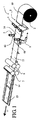
図1を参照すると、本発明による切断装置5が「切断」部分のみがこの図に表わされる郵便物1の準備装置中にその用途を見出す。この郵便物準備機械1は従来の機械とは封筒14が、この場合に、折込文書13が印刷されかつ切断される紙幅部である材料10の幅部の全体部分をなす点で区別される。この新しい技術は進行速度アップ、安全性ならびに折込による原価低減といった郵便物の完全性の強化といった多くの利点を示す。この新技術はこのため、文書13および/または封筒14の数やサイズが手紙からその他まで変化可能な、非直線かつ非繰り返しで、制御されて長さ方向に変動する外形12による紙10の幅部内の帯11の切断用に設置される本発明の対象である「動的」いわれる切断装置5を必要とする。図2Aは2枚の封筒14と3つの文書13が含まれる帯11が切断される紙10の幅部の第1供試体を図解する。図2Bは相互にずらされ、各帯11,11‘が適当な外形12,12’を有する各2枚の封筒14と3つの文書13が含まれる2本の帯11,11‘が切断される紙10‘の2倍幅部の第2供試体を図解する。勿論、本発明による切断装置5は文房具、織物、プラスチック製造業、鋼板工場などの業界で「動的」といわわれる切断を必要とする他の分野でも応用可能であると同時に、材料10の幅部は紙、厚紙、織物、非織布、プラスチックフィルム、鋼板などの幅部でありえる。
Referring to FIG. 1, the
図1を参照すると、紙10の幅部は巻き取り機2により支持される事前印刷されたロールから解かれる。これらはまたつながっている印字機から直接取り出すことも可能である。紙10の幅部は第1ローラー引張装置3を横切った後、封筒14の横方向折り返し部16に折り目15を付けるため設置される溝きり装置4が引き続き折込操作を助ける。紙の幅部10は2つの切断工具60とその切断屑自動排出装置の吸入導管8によってのみ示される切断装置5を横切る。この切断装置5により文書13がほどよい幅部に整えられると同時に、封筒14の横方向折り返し部16が作られ、これらが文書13の幅部を越える紙帯11形成用の長さ方向縁部または幅部の縁部10の切断が可能となる。この切断装置5により発生する紙屑は中央吸入装置(図示されず)を経由して貯蔵容器の方向に吸入導管8により自動的に排出される。ロール紙10は第2ローラー引張装置6を横切る行程を追った後、例えば刃付き回転筒を利用する横方向切断装置7により選定と積重ねの装置の後に折込と封筒14の文書13(図示されず)と一緒の閉鎖の装置を供給するための文書13の封筒14からの分離が可能となる。横方向切断装置7は切断様式に応じて稼動される中央制御装置(図示されず)により制御され、封筒14の切断長さは文書13のものとは異なる。この稼動は、文書13と封筒14の間の切断様式を特定する目的で補完される情報プログラムによりあるいは幅部10または紙帯11にわたり印刷される諸基準点を見出すために設置されるピックアップにより搬送される信号により得られる。
Referring to FIG. 1, the width of
図3および図4に参照されて図示される切断装置5には例えば、機械溶接などで製作されると同時に、矢印Dにより示されるロール紙10縦進行方向に垂直に配置される少なくとも1つの対向部品70と協働する少なくとも第1組の切断工具60支持用に設置される台座50が含まれ、ロール紙10は事前に決められかつ制御されるランダムな順番12で変動する長さ方向外形を生み出すためにロール紙10の長さ方向縁を切断するように切断工具60と対向部品70の間を縦に進行する。このため、切断工具60は、各切断工具60の切断角度を修正するように対向部品70に垂直な回転軸Aと2つの切断工具60間の間隔を修正するように対向部品70に平行な平行移動軸Bの2軸により台座50に関して移動するよう取り付けられる。この例では、各切断工具60は、事前に決められるランダムな順番12で長さ方向に変動する外形に応じて中央制御装置(図示されず)による2つの回転と1つの平行移動の軸による組み合わせで制御される回転駆動機構80と平行移動駆動機構90により切断される。
The
対向部品70には台座50に関してその軸C周りに回転移動する取り付けられる筒71が含まれる。諸用途により、この対向部品70は勿論様々な形態を有することができると同時に、台座50に関して固定されことができる。この例では、筒71は1つのプーリー72だけが示されると同時に台座50の横壁と一体の軸受け内に誘導される機構によるかあるいはその他のあらゆる同等手段による回転で駆動される。駆動機構は直接連結されるかまたは対向部品70の軸の機械伝動装置によるあらゆるタイプの駆動装置から構成されと同時に、ロール紙10の縦方向進行の速度に応じて中央制御装置(図示されず)により制御される。筒71は好ましくは切断工具60のものより長いと同時に、熱、化学等の処理により得られる例えば63HRCに等しい耐久性のスチールから製作可能である。
The facing
示された例では、各切断工具60には、例えば、61HRCに相当する耐久性のスチール製であるとともに本体62に取り付けられる対向部品70により回転駆動されるその軸E周りに回転する円状刃61が含まれる。軸Cを通る軸Aならびに軸Aを通る軸E、筒71上の円状刃61の支点Pは軸A上の直線に並べられる。当然ながら、その他の構成も可能である。本体62は玉軸受けなどによる軸Bの横断方向誘導具51に沿ったキャリッジ50に関する平行移動で移動キャリッジ63により支持される。
In the example shown, each cutting
各切断工具60の回転駆動機構80は対向する移動キャリッジ63上に乗せられる。これには示された例では、減速機を形成する本体62と一体の大歯車83を噛合する小歯車原動機82により切断工具60に連結されたサーボ原動機81が含まれる。本体62は玉軸受けなどによる軸64の端部の移動キャリッジ63に関する回転で誘導される。この軸64は少なくとも1ヶ所の対向部品70と接触しないと同時に、ロール紙10の通り抜けを可能にする持ち上がった停止位置と対向部品70と破砕により切断を行うと同時に円状刃61の損耗を埋め合わせるために同時に利用されるある一定の圧力下で接触する下がった作動位置との間の円状刃61の鉛直移動用に設置される圧搾機構を形成するこれも移動キャリッジ63に乗せられる空圧などのジャッキ65の一部をなす。小型の歯車原動機82の幅部はすっかり噛合しつつその停止位置と作動位置の間の円状刃61の鉛直移動を可能にする大歯車83のものより大きい。当然ながら、その他の圧搾機構も合わせことが可能である。
The
平行移動駆動機構90は2つの切断工具60と共通であると同時に、示された例では、2つの小歯車93を対向する直径方向に噛合し、そのそれぞれは同期をとってかつ対向する方向のこれらの移動キャリッジ63の平行移動用の移動キャリッジ63と一体の平板歯車94を噛合する小型歯車原動機92により切断工具60に結合されたサーボ原動機91を含む。移動キャリッジ63の逆の平行移動はサーボ原動機91の回転方向を逆にして得られる。
The
中央制御装置(図示されず)により別々の駆動装置、特にサーボ原動機81,91の機能稼動が極めて簡単に、極めて正確に、かつロール紙10内の変動する長さ方向切断外形12に応じた組合が可能となり、この外形はランダムで、非周期的かつ完全に制御される。この中央制御装置は補完情報プログラムによりあるいはまた文書13と封筒14との間の切断様式を特定する目的で紙11の幅部10または帯にわたる印刷基準点探知用に設置されるピックアップにより引き渡される信号により稼動される。
A central controller (not shown) makes it possible for the functional operation of the separate drive units, in particular the
当然ながら、その他の駆動機構80,90も合わせることができ、不可欠なことは、その軸周りの回転と対向部品70の軸に平行な平行移動の組み合わせ移動により切断工具60の極めて精度よくかつ極めて迅速に移動させることにある。
Of course, the
これらの駆動機構80,90の機構で利用される駆動装置81,91は、その他のタイプの原動機あるいは原動減速機、ジャッキ、電磁石などでも構成可能である。しかしながら、サーボ原動機81,91の利用は、出足の遅れも、停止慣性もなく極めて精度よくこれらの原動機の移動の制御が可能であるので制御に関する大きな柔軟性を有する利点を有する。
The
回転駆動機構80のためには、切断工具60による駆動装置81の設置が好ましく、これらの切断工具60は平行移動が可能である。2つの切断工具60用の駆動装置により設置機械伝動装置に関する実施が複雑となろう。
For the
平行移動駆動機構90については、1組の切断工具60による駆動装置91の設置という事実により2つの切断工具60の同時移動の確保が可能となる。図3および図4に示された機械平行移動装置はその他の別の同等装置で置き換えることも可能であり、3つの例が図6から図8に示される。
With respect to the parallel
図5Aおよび図5Bは各切断工具60‘に円状刃61ならびに円状対抗刃61’が含まれる本発明による別の切断装置5‘を示しており、これらの刃ははさみ切断を生ずるための切断地帯に接している。この実施例では、対向部品70’には対向部品61‘の延長部に配置されると同時に材料幅部10の誘導用に設置されるローラー71‘が含まれる。刃61、対向刃61’およびローラー71‘により形成される全体は移動キャリッジ63に乗せられると同時に、前出例と類似の回転駆動機構80で連結される揺動支持材53により支持される。円状刃61と61’は下部円状刃61‘とローラー71’に直接または機械伝動装置により連結される駆動装置73によりこれらの軸Eの周りに回転駆動される。駆動装置73はあらゆるタイプの原動機などであってよい。この実施例では、ジャッキ65で構成される圧搾機構はもはや必要ない。材料幅部10の切断装置5‘内通り抜けのために、揺動支持材53が切断地帯の刃61,61’の取り出し用の平行移動駆動機構90により移動される。その後、切断開始には、揺動支持材53が挟みのように切断地帯に刃61,61‘をかみ合わせるために逆転方向に移動される。
この切断装置5’には最良品質の切断が生まれる利点がある。
FIGS. 5A and 5B show another
This cutting device 5 'has the advantage of producing the best quality cutting.
当然ながら、その他の切断工具も利用可能であり、ランダムな順番で制御されて変動する長さ方向外形による材料帯の連続切断が可能であることが不可欠である。このため、円状刃61,61‘をレーザーあるいは超音波のビーム、高圧下の流体噴射、鋭利な尖端などで置き換えることも考えられる。
Of course, other cutting tools can also be used, and it is essential to be able to continuously cut the strip of material with a longitudinal profile that is controlled and varied in a random order. For this reason, it is also conceivable to replace the
図6では、平行駆動機構100に、逆ねじ山101a, 101b付きウォームネジくぎ101による機械伝動装置が含まれ、このウォームネジくぎ101はこれらの軸受け102,103内に誘導されると同時に、その端部の1端に連結されるものの図示はされてはいない原動機のような駆動装置により回転制御される。
In FIG. 6, the
各ねじ山101a、101bは移動キャリッジ63に設置されるナット104と噛合し、ある方向のウォームネジくぎ101の回転により移動キャリッジ63の平行移動と同時に、つまりは切断工具60が同時にかつ対向する両方向に起動し、逆の平行移動が駆動装置の回転方向とは逆に生じる。
Each
図7の平行移動駆動機構110には小連結棒112,113を伴った装置による機械式伝動装置が含まれる。電動原動機、サーボ原動機などといった駆動装置111により、中心がずらされた小連結棒113によりその原動機軸上で移動キャリッジ63上に連結される連接棒112が支持され、切断工具60の平行移動と同時にその反対方向にも駆動装置111の回転が引き起こされ、逆の平行移動が駆動装置111の回転方向を逆転させながら生み出される。
The
図8は諸小連結棒123がそれぞれ共通小歯車原動機125に噛合する歯車124に連結される点が異なる前出と同様の平行移動駆動機構120を示す。このように、駆動装置は同一回転方向に回転可能であると同時に、移動キャリッジ63の平行移動と同時にその反対方向への2種の移動を開始し、各平行移動は駆動装置の半回転上(図示されず)に得られる。この方案により平行移動の方向を変えることが必要になる度に、その各回転方向を逆転させるための駆動装置の強制停止が回避される。
FIG. 8 shows a
本発明による切断装置10,10‘は、第1組切断工具60の軸または同一材料幅部内の第2帯の切断目的でずれた軸内に配置される第2組の切断工具60,60’を通じて、また、図2Bの例により例示されるように、第1組と同じかまたは異なる変動する長さ方向外形に応じて補完可能である。
The cutting
図1および図2に示された例では、文書13と封筒14は、あらゆるタイプの印字機により分離された場所で紙10幅部にその折込みのために予定された順番で順次続けて連続印刷され、該ロール紙10は郵便物準備機1に供給されるためにロールの形で再び巻き取られた。この技術については、各文書は任意の特定の封筒に合わせられると同時に仕向けられることが容易に可能である。この郵便物準備機1は、従って、郵便物の完全性重視が難なく保証されるとともに区域別仕分けと同じ位従来の郵便物にも十分充当可能であって、つまりは正常な文書が正常な封筒内に納まることなる。
In the example shown in FIGS. 1 and 2, the
ロールが巻き取り機2に設置されるときに、ロール紙10は別々の装置3から7までの装置内を越えて通り抜ける。図3および図4による切断装置5からの通り抜けのため、ジャッキ65により円状刃61が持ち上げられた後、印刷されたロール紙10に関して切断工具60の調整固定が行われる。平行して、情報プログラムが切断帯に対応する中央制御装置に投入されるかあるいは既に記憶されたプログラムが選択される。円状刃61が作動位置に下げられると同時に、機械が作動開始する。ローラー引張装置6により引っ張られる紙幅部1は、文書13の幅と封筒14の幅と横方向折り返し16により決定されるランダムな順番で変動する外形に応じてロール紙10の長さ方向縁を切断する切断装置5を横断して、連続して縦方向に進行する。文書13より大きい封筒14の折り返し16が形成されるために、中央制御装置により切断工具60の回転駆動機構80ならびに平行移動駆動機構90が同時にかつ円状刃61の移動のために曲線切断線の生成が可能となる回転と平行移動の組み合わせに応じて組み合わせられるように運転される。
When the roll is installed in the winder 2, the
図5Aおよび図5Bによる切断装置5‘の機能形態は刃61の持ち上げと取り下ろしがもはや不要である以外は同様である。
The functional configuration of the cutting device 5 'according to FIGS. 5A and 5B is the same except that the lifting and unloading of the
この説明から、本発明により設定された目的は、単純でコストがかからなくかつ使い方の柔軟な切断装置、すなわち、繰り返しの概念から全く外れたロール紙10の縦方向進行中のあらゆる時点におけると同時に制御された方法であらゆる形状の長さ方向切断線の生成を可能にする切断工具60,60‘等を用いて達成可能であることがはっきり引き出される。
From this description, the objective set by the present invention is that at any point during the longitudinal progression of the
本発明は説明された実施例に限定されずに、付録の請求項に定義された保護範囲に留まるかぎり専門家にとって明らかなあらゆる変更例や変型例に拡大される。 The invention is not limited to the embodiments described, but extends to all modifications and variations apparent to the expert as long as they remain within the scope of protection defined in the appended claims.
本発明とその諸利点は付録図を参照して非限定的な例として挙げられるいくつかの実施形態例に関する次の説明によりさらによく明らかになろう。 The invention and its advantages will become better apparent from the following description of some exemplary embodiments given by way of non-limiting example with reference to the accompanying figures.
Claims (16)
s The discharge device is installed in the vicinity of each cutting tool (60, 60 ') and at the same time includes at least one suction conduit (8) connected to the container by a pipe passing through the central suction device. Cutting device s according to claim 15
Applications Claiming Priority (2)
| Application Number | Priority Date | Filing Date | Title |
|---|---|---|---|
| FR0507878A FR2888768B1 (en) | 2005-07-25 | 2005-07-25 | DEVICE FOR LONGITUDINAL CUTTING OF A LAIZE OF CONTINUOUSLY SHAPING MATERIAL FOR FORMING A VARIABLE LONGITUDINAL PROFILE STRIP |
| PCT/FR2006/001798 WO2007012739A1 (en) | 2005-07-25 | 2006-07-24 | Device for longitudinally cutting a web of continuously moving material to form a strip with variable longitudinal profile |
Publications (1)
| Publication Number | Publication Date |
|---|---|
| JP2009502526A true JP2009502526A (en) | 2009-01-29 |
Family
ID=36127350
Family Applications (1)
| Application Number | Title | Priority Date | Filing Date |
|---|---|---|---|
| JP2008523405A Pending JP2009502526A (en) | 2005-07-25 | 2006-07-24 | Longitudinal cutting device for continuous longitudinally proceeding material width part for forming outer band with variable length direction |
Country Status (8)
| Country | Link |
|---|---|
| US (1) | US20080115641A1 (en) |
| EP (1) | EP1922187A1 (en) |
| JP (1) | JP2009502526A (en) |
| BR (1) | BRPI0613655A2 (en) |
| CA (1) | CA2612909A1 (en) |
| FR (1) | FR2888768B1 (en) |
| IL (1) | IL188491A0 (en) |
| WO (1) | WO2007012739A1 (en) |
Families Citing this family (35)
| Publication number | Priority date | Publication date | Assignee | Title |
|---|---|---|---|---|
| DE102008035278A1 (en) * | 2008-07-29 | 2010-02-04 | Dgr-Graphic Gmbh | Longitudinal cutter for cutting e.g. spine tape material to book block height in spine taping station of adhesive binder, has quetsch roller blade pivotable around pivoting axis and supported at holder that is movable upto height dimension |
| NL1036870C2 (en) * | 2009-04-17 | 2010-10-19 | Ten Cate Itex B V | DEVICE FOR MANUFACTURING A FIBER MAT BY WEAVING. |
| DE102009032653A1 (en) * | 2009-07-09 | 2011-01-13 | Marc Tschech | Device for separating in particular for separating welding plastic sheets |
| RU2612924C2 (en) | 2011-11-10 | 2017-03-13 | ПЭКСАЙЗ, ЭлЭлСи | Vertical cardboard plant with unloading guide |
| WO2013098356A1 (en) * | 2011-12-30 | 2013-07-04 | Philip Morris Products S.A. | Apparatus and method for supplying a continuous web of crimped sheet material |
| WO2013106180A1 (en) | 2012-01-09 | 2013-07-18 | Packsize Llc | Converting machine with an upward outfeed guide |
| CA2947142C (en) * | 2014-04-28 | 2022-07-19 | Arkk Engineering | Weight material cutting, dispensing and applying systems |
| CN104527014B (en) * | 2014-12-19 | 2017-02-22 | 安徽广德金鹏新材料制造有限公司 | Separating mechanism for co-extruded strips of profiles |
| US10093438B2 (en) | 2014-12-29 | 2018-10-09 | Packsize Llc | Converting machine |
| CN105108791A (en) * | 2015-09-18 | 2015-12-02 | 江苏冰城电材股份有限公司 | Resin-rich mica tape slitting device |
| CN105383989A (en) * | 2015-12-03 | 2016-03-09 | 太仓市中厚机械有限公司 | Transparent tape slitting machine |
| EP3471953B1 (en) | 2016-06-16 | 2020-12-16 | Packsize LLC | A box template production system and method |
| US10850469B2 (en) | 2016-06-16 | 2020-12-01 | Packsize Llc | Box forming machine |
| CN106346558A (en) * | 2016-08-25 | 2017-01-25 | 安庆市兴丰工贸有限公司 | Laser drilling device for plastic film |
| CN106272623A (en) * | 2016-11-14 | 2017-01-04 | 湖南省客来宝生物能源科技有限公司 | A kind of Biodegradable films automatic cutting means |
| US11242214B2 (en) | 2017-01-18 | 2022-02-08 | Packsize Llc | Converting machine with fold sensing mechanism |
| SE541921C2 (en) | 2017-03-06 | 2020-01-07 | Packsize Llc | A box erecting method and system |
| SE540672C2 (en) | 2017-06-08 | 2018-10-09 | Packsize Llc | Tool head positioning mechanism for a converting machine, and method for positioning a plurality of tool heads in a converting machine |
| DE102017215712A1 (en) | 2017-09-06 | 2019-03-07 | Bhs Corrugated Maschinen- Und Anlagenbau Gmbh | Link interface arrangement |
| CN107598583B (en) * | 2017-10-19 | 2023-11-17 | 亦宸五金(浙江)股份有限公司 | Automatic processing device for foundation bolts |
| US11173685B2 (en) | 2017-12-18 | 2021-11-16 | Packsize Llc | Method for erecting boxes |
| US11247427B2 (en) | 2018-04-05 | 2022-02-15 | Avercon BVBA | Packaging machine infeed, separation, and creasing mechanisms |
| US11305903B2 (en) | 2018-04-05 | 2022-04-19 | Avercon BVBA | Box template folding process and mechanisms |
| WO2019246344A1 (en) | 2018-06-21 | 2019-12-26 | Packsize Llc | Packaging machine and systems |
| SE543046C2 (en) | 2018-09-05 | 2020-09-29 | Packsize Llc | A box erecting method and system |
| CN109179011A (en) * | 2018-09-21 | 2019-01-11 | 浙江华越丝绸制品有限公司 | A kind of fabric trimming device |
| US11524474B2 (en) * | 2018-11-30 | 2022-12-13 | Packsize Llc | Adjustable cutting and creasing heads for creating angled cuts and creases |
| DE112020000348T5 (en) | 2019-01-07 | 2021-09-16 | Packsize Llc | Carton erecting machine |
| US11701854B2 (en) | 2019-03-14 | 2023-07-18 | Packsize Llc | Packaging machine and systems |
| CN110103271B (en) * | 2019-03-28 | 2021-02-09 | 上海汉合纸业有限公司 | Automatic paper cutter for roll paper |
| CN110407002A (en) * | 2019-06-27 | 2019-11-05 | 安徽东锦服饰有限公司 | A kind of clothes cloth all pointss device and its application method with draw-in and draw-off function |
| CN110356905A (en) * | 2019-07-02 | 2019-10-22 | 深圳市友利特精密机械制造有限公司 | Adjust roller group and cutting machine |
| DE202020104847U1 (en) * | 2020-08-21 | 2020-11-04 | Michael Hörauf Maschinenfabrik Gmbh Und Co. Kg | Circular knife device |
| CN113263603B (en) * | 2021-05-19 | 2022-07-19 | 中建材创新科技研究院有限公司 | Gypsum building material is surely chased after and is cut processing application apparatus and control system |
| CN114803656A (en) * | 2022-04-19 | 2022-07-29 | 江西力征材料有限公司 | Cutting machine is used in dry film production |
Family Cites Families (13)
| Publication number | Priority date | Publication date | Assignee | Title |
|---|---|---|---|---|
| GB702116A (en) * | 1952-05-27 | 1954-01-06 | Holweg Const Mec | Improvements in or relating to devices for cutting continuously travelling webs of non-fibrous material |
| US4071997A (en) * | 1976-04-27 | 1978-02-07 | Gunther Business Systems, Inc. | Mechanism and method of making an envelope |
| US4189895A (en) * | 1977-12-16 | 1980-02-26 | Compak Systems, Inc. | Method and apparatus for making envelope assemblies |
| DE3714662A1 (en) * | 1987-05-02 | 1988-11-17 | Kronseder Maschf Krones | METHOD AND DEVICE FOR CUTTING CONTOURED LABELS |
| JPH0767678B2 (en) * | 1988-07-08 | 1995-07-26 | 豊田合成株式会社 | Weather strip manufacturing equipment |
| US5197262A (en) * | 1989-06-01 | 1993-03-30 | Webcraft Technologies, Inc. | Assembly for producing a mass distributable printed packet |
| JP2901413B2 (en) * | 1992-04-22 | 1999-06-07 | 北村機電株式会社 | Stripping device for band material for wound iron core |
| DE4218272A1 (en) * | 1992-06-03 | 1992-10-29 | Voith Gmbh J M | Trimming fast moving paper band - by using rotary cutter, water jet or laser, entering at oblique angle |
| DE4314095A1 (en) * | 1993-04-29 | 1994-11-03 | B & B Maschinenbau Gmbh | Apparatus for cutting veneer |
| US5918519A (en) * | 1994-07-16 | 1999-07-06 | Bhs Corrugated Maschinen- Und Anlagenbau Gmbh | Apparatus for the manufacture of sheets of corrugated board of variable size |
| WO1996016773A1 (en) * | 1994-11-28 | 1996-06-06 | Three Dimensional Trim Corporation | Trimming apparatus and method |
| DE19625818A1 (en) * | 1996-06-28 | 1998-01-02 | Bielomatik Leuze & Co | Device and method for processing sheet material |
| US6865864B2 (en) * | 2002-05-31 | 2005-03-15 | Robert E. Katz | Inline formed crossfold package and method |
-
2005
- 2005-07-25 FR FR0507878A patent/FR2888768B1/en not_active Expired - Fee Related
-
2006
- 2006-07-24 BR BRPI0613655-9A patent/BRPI0613655A2/en not_active Application Discontinuation
- 2006-07-24 WO PCT/FR2006/001798 patent/WO2007012739A1/en not_active Application Discontinuation
- 2006-07-24 EP EP06778906A patent/EP1922187A1/en not_active Withdrawn
- 2006-07-24 JP JP2008523405A patent/JP2009502526A/en active Pending
- 2006-07-24 CA CA 2612909 patent/CA2612909A1/en not_active Abandoned
-
2007
- 2007-12-30 IL IL188491A patent/IL188491A0/en unknown
-
2008
- 2008-01-25 US US12/019,806 patent/US20080115641A1/en not_active Abandoned
Also Published As
| Publication number | Publication date |
|---|---|
| US20080115641A1 (en) | 2008-05-22 |
| WO2007012739A1 (en) | 2007-02-01 |
| BRPI0613655A2 (en) | 2011-01-25 |
| FR2888768B1 (en) | 2008-10-24 |
| CA2612909A1 (en) | 2007-02-01 |
| IL188491A0 (en) | 2008-04-13 |
| FR2888768A1 (en) | 2007-01-26 |
| WO2007012739A8 (en) | 2007-04-26 |
| EP1922187A1 (en) | 2008-05-21 |
Similar Documents
| Publication | Publication Date | Title |
|---|---|---|
| JP2009502526A (en) | Longitudinal cutting device for continuous longitudinally proceeding material width part for forming outer band with variable length direction | |
| EP1426152B1 (en) | An apparatus for cutting pieces of material into appropriate shaped portions | |
| US9259892B2 (en) | Creasing machine | |
| JPH05208775A (en) | Hole line forming device and rewinding device | |
| KR102288466B1 (en) | Fabric cuttinf apparatus using ultrasonic wave | |
| CN211225726U (en) | Welding flattening device for cloth | |
| US5358164A (en) | Drive apparatus for a driving of at least one oscillating shaft and an intermittent feeding apparatus including the drive apparatus | |
| EP2719527A1 (en) | Device for producing a cushioning product from paper | |
| CN209161070U (en) | A kind of folding tea glazing machine | |
| US3468202A (en) | Machine for cutting flat flexible multiwall tubing | |
| CN205471916U (en) | A high -efficient non -woven fabric slitter for zigzag lace | |
| US1400777A (en) | Paper-cutting device | |
| US1954605A (en) | Slicing machine | |
| EP3981584A1 (en) | Apparatus and method for manufacturing of spirally wound tubes | |
| CN211591533U (en) | Sheet positioning embossing device | |
| DE19830978C2 (en) | Method for cutting a printing material web in the longitudinal direction and cutting device for cutting the printing material web | |
| RU2179514C1 (en) | Method of cross cutting of blanks of preset length from continuously moving material web | |
| CN108975019A (en) | A kind of folding tea glazing machine | |
| US255632A (en) | jaegee | |
| JPS61192663A (en) | Cloth spreading machine | |
| US528542A (en) | Paper cutting and embossing press | |
| US1168130A (en) | Rug-cutting machine. | |
| RU2190506C2 (en) | Shears for sheet material | |
| PL241509B1 (en) | Device for the production of spiral tubes and method for the production of spiral tubes |