JP2009277726A - Laminated circuit board, motor controller and steering device for vehicle - Google Patents

Laminated circuit board, motor controller and steering device for vehicle Download PDF

Info

Publication number
JP2009277726A
JP2009277726A JP2008125118A JP2008125118A JP2009277726A JP 2009277726 A JP2009277726 A JP 2009277726A JP 2008125118 A JP2008125118 A JP 2008125118A JP 2008125118 A JP2008125118 A JP 2008125118A JP 2009277726 A JP2009277726 A JP 2009277726A
Authority
JP
Japan
Prior art keywords
housing
substrate body
layer
shaft
circuit board
Prior art date
Legal status (The legal status is an assumption and is not a legal conclusion. Google has not performed a legal analysis and makes no representation as to the accuracy of the status listed.)
Pending
Application number
JP2008125118A
Other languages
Japanese (ja)
Other versions
JP2009277726A5 (en
Inventor
Motoo Nakai
基生 中井
Shigeki Nagase
茂樹 長瀬
Kouya Yoshida
航也 吉田
Sanehiro Uchida
修弘 内田
Current Assignee (The listed assignees may be inaccurate. Google has not performed a legal analysis and makes no representation or warranty as to the accuracy of the list.)
JTEKT Corp
Original Assignee
JTEKT Corp
Priority date (The priority date is an assumption and is not a legal conclusion. Google has not performed a legal analysis and makes no representation as to the accuracy of the date listed.)
Filing date
Publication date
Application filed by JTEKT Corp filed Critical JTEKT Corp
Priority to JP2008125118A priority Critical patent/JP2009277726A/en
Publication of JP2009277726A publication Critical patent/JP2009277726A/en
Publication of JP2009277726A5 publication Critical patent/JP2009277726A5/ja
Pending legal-status Critical Current

Links

Images

Classifications

    • HELECTRICITY
    • H01ELECTRIC ELEMENTS
    • H01LSEMICONDUCTOR DEVICES NOT COVERED BY CLASS H10
    • H01L2924/00Indexing scheme for arrangements or methods for connecting or disconnecting semiconductor or solid-state bodies as covered by H01L24/00
    • H01L2924/0001Technical content checked by a classifier
    • H01L2924/0002Not covered by any one of groups H01L24/00, H01L24/00 and H01L2224/00

Abstract

<P>PROBLEM TO BE SOLVED: To prevent a foreign matter from being generated from a laminated circuit board. <P>SOLUTION: A power substrate 78 includes a substrate body 301 composed by laminating first, third, fifth and seventh layers 311, 313, 315 and 317 as insulating layers and second, fourth and sixth layers 312, 314 and 316 as layers including conductors. The outer side face 301c of the substrate body 301 is covered with a cover member 304. Thus, a material configuring the insulating layers is prevented from dispersing as dust (foreign matter) from the outer side face 301c of the substrate body 301. <P>COPYRIGHT: (C)2010,JPO&INPIT

Description

本発明は、積層回路基板、モータ制御装置および車両用操舵装置に関する。   The present invention relates to a laminated circuit board, a motor control device, and a vehicle steering device.

通常、積層回路基板は、導体層と絶縁層とを積層して形成されている(例えば、特許文献1〜4参照)。
特開2002−9435号公報 特開平8−78849号公報 特開平5−243743号公報 特開2006−237115号公報
Usually, a laminated circuit board is formed by laminating a conductor layer and an insulating layer (see, for example, Patent Documents 1 to 4).
JP 2002-9435 A JP-A-8-78849 JP-A-5-243743 JP 2006-237115 A

積層回路基板は、導体層と絶縁層とが積層された製造中間体を打ち抜き加工することにより形成される。絶縁層は、例えばセラミック等を含有する合成樹脂を用いて形成されている。このため、打ち抜きによって切断された切断面に、セラミック粉等の粉塵(異物)が発生するおそれがある。このような粉塵は、積層回路基板に電子部品を接合する際の接合不良の原因となる可能性がある。特に、電動パワーステアリング装置の電動モータを制御する制御基板において、このような粉塵は、モータ軸受等に侵入して軸受の摩耗を促進する原因となるおそれがある。   The laminated circuit board is formed by punching a manufacturing intermediate in which a conductor layer and an insulating layer are laminated. The insulating layer is formed using, for example, a synthetic resin containing ceramic or the like. For this reason, there is a possibility that dust (foreign matter) such as ceramic powder may be generated on the cut surface cut by punching. Such dust may cause bonding failure when bonding electronic components to the laminated circuit board. In particular, in a control board that controls an electric motor of an electric power steering apparatus, such dust may enter a motor bearing or the like and promote wear of the bearing.

本発明は、かかる背景のもとでなされたもので、積層回路基板から異物が生じることを防止できる積層回路基板、モータ制御装置および車両用操舵装置を提供することを目的とする。   The present invention has been made under such a background, and an object of the present invention is to provide a laminated circuit board, a motor control device, and a vehicle steering device that can prevent foreign matters from being produced from the laminated circuit board.

上記目的を達成するため、本発明は、導体(312a,312c,314a,316a,316b,316d)を含む層(312,314,316)と絶縁層(311,313,315,317)とを積層してなる基板本体(301)と、被覆部材(304)とを備え、上記基板本体は、積層方向(D)に対向する表面(301a)および裏面(301b)と、側面(301c)とを含み、上記側面は、上記被覆部材によって被覆されていることを特徴とする積層回路基板(78)である(請求項1)。   In order to achieve the above object, the present invention comprises a layer (312, 314, 316) including conductors (312a, 312c, 314a, 316a, 316b, 316d) and an insulating layer (311, 313, 315, 317). The substrate body includes a front surface (301a) and a back surface (301b) facing the stacking direction (D), and a side surface (301c). The side surface is a laminated circuit board (78) covered with the covering member (claim 1).

例えば、積層回路基板は、導体を含む層と絶縁層とが積層された製造中間体を打ち抜き加工することにより、形成される。絶縁層は、例えばセラミック等を含有する合成樹脂を用いて形成されている。また、積層回路基板の側面は、導体を含む層と絶縁層とが打ち抜き加工によって露出している。
本発明によれば、基板本体の側面が被覆部材で覆われていることにより、例えば、この側面から、絶縁層を構成する材料が粉塵(異物)として飛散することを防止できる。これにより、基板本体の表面等に異物が付着してしまうことを防止でき、積層回路基板に電子部品を接合する際の接合不良を確実に防止できる。
For example, a laminated circuit board is formed by stamping a manufacturing intermediate in which a layer including a conductor and an insulating layer are laminated. The insulating layer is formed using, for example, a synthetic resin containing ceramic or the like. Moreover, the layer including the conductor and the insulating layer are exposed on the side surface of the multilayer circuit board by punching.
According to the present invention, since the side surface of the substrate main body is covered with the covering member, for example, the material constituting the insulating layer can be prevented from being scattered as dust (foreign matter) from this side surface. Thereby, it can prevent that a foreign material adheres to the surface etc. of a board | substrate body, and can prevent the joining defect at the time of joining an electronic component to a laminated circuit board reliably.

また、本発明において、上記絶縁層は、基材と、この基材よりも熱伝導率が高い熱伝導材とを含む場合がある(請求項2)。この場合、絶縁層の熱伝導性を高くすることができ、基板本体の放熱性をより高くすることができる。
また、本発明において、上記基板本体にはビアホール(308)が設けられ、上記基板本体の表面は、ワイヤボンディングによる接合のための接合部(326)を含み、上記接合部は、上記積層方向に関して、上記ビアホールを避けて配置されている場合がある(請求項3)。この場合、基板本体のうちビアホールが形成されている部分は、ビアホールの形成作業に伴って基板本体表面に凹凸が生じることとなる。その一方で、ビアホールが形成されていない部分は、ビアホールを形成する作業が行われないので、基板本体の表面に凹凸が生じることが無い。このように、基板本体の表面のうち凹凸が生じていない平滑な部分に接合部が設けられるので、接合部と、この接合部にボンディングされたボンディングワイヤとの接合を確実に行うことができ、両者の接合強度を十分に確保することができる。しかも、ボンディングパッドのような別部品を用いて接合部を形成する必要がないので、コスト安価である。
Moreover, in this invention, the said insulating layer may contain a base material and a heat conductive material whose heat conductivity is higher than this base material (Claim 2). In this case, the thermal conductivity of the insulating layer can be increased, and the heat dissipation of the substrate body can be further increased.
In the present invention, the substrate body is provided with a via hole (308), and the surface of the substrate body includes a bonding portion (326) for bonding by wire bonding, and the bonding portion is related to the stacking direction. In some cases, the via holes are disposed away from the via holes. In this case, the portion of the substrate body where the via hole is formed has irregularities on the surface of the substrate body as the via hole is formed. On the other hand, since the operation for forming the via hole is not performed in the portion where the via hole is not formed, the surface of the substrate body is not uneven. Thus, since the joint portion is provided in the smooth portion of the surface of the substrate body where the irregularities are not generated, the joint portion and the bonding wire bonded to the joint portion can be reliably bonded, It is possible to sufficiently secure the bonding strength between the two. In addition, since it is not necessary to form a joint using another component such as a bonding pad, the cost is low.

また、本発明において、上記積層回路基板は、基板本体の裏面に接合される金属ベース(302)と、この金属ベースに形成される位置決め孔(321a,321b)とを備え、上記位置決め孔に、上記金属ベースが設置される基板設置部材(77a)に形成された位置決め部材(318,319)を嵌合可能である場合がある(請求項4)。この場合、基板設置部材に対する積層回路基板の位置決めの精度をより高くすることができる。   In the present invention, the multilayer circuit board includes a metal base (302) bonded to the back surface of the substrate body and positioning holes (321a, 321b) formed in the metal base. In some cases, positioning members (318, 319) formed on the board installation member (77a) on which the metal base is installed can be fitted (claim 4). In this case, the positioning accuracy of the laminated circuit board with respect to the board installation member can be further increased.

また、本発明において、上記の積層回路基板と、上記積層回路基板の基板本体に実装されたモータ駆動用素子(83)を含むモータ駆動回路(82)とを含む場合がある(請求項5)。この場合、積層回路基板から粉塵(異物)が発生することが防止されているので、このような異物がモータの軸受等に侵入してモータの軸受の摩耗が促進されることを防止できる。   Further, the present invention may include the above-described multilayer circuit board and a motor drive circuit (82) including a motor drive element (83) mounted on the board body of the multilayer circuit board (Claim 5). . In this case, since dust (foreign matter) is prevented from being generated from the laminated circuit board, it is possible to prevent such foreign matter from entering the motor bearing or the like and promoting wear of the motor bearing.

また、本発明において、モータ制御装置(78)と、上記モータ制御装置によって駆動され、操舵機構(4)に操舵力を付与する電動モータ(18)とを備える場合がある(請求項6)。この場合、積層回路基板に実装される電子部品の接合不良が確実に防止されているとともに、モータの軸受等の摩耗が抑制された車両用操舵装置を実現することができる。   In the present invention, there may be provided a motor control device (78) and an electric motor (18) that is driven by the motor control device and applies a steering force to the steering mechanism (4). In this case, it is possible to realize a vehicle steering apparatus in which the bonding failure of the electronic components mounted on the multilayer circuit board is reliably prevented and the wear of the motor bearings and the like is suppressed.

なお、上記において、括弧内の数字等は、後述する実施の形態における対応構成要素の参照符号を表すものであるが、これらの参照符号により特許請求の範囲を限定する趣旨ではない。   In the above description, numbers in parentheses represent reference numerals of corresponding components in the embodiments described later, but the scope of the claims is not limited by these reference numerals.

以下には、図面を参照して、本発明の実施形態について具体的に説明する。
図1は、本発明の一実施形態に係る車両用操舵装置としての電動パワーステアリング装置1の概略構成を示す模式図である。
図1を参照して、電動パワーステアリング装置1は、操舵部材としてのステアリングホイール2と、ステアリングホイール2の回転に連動して転舵輪3を転舵する操舵機構4と、運転者の操舵を補助するための操舵補助機構5とを備えている。ステアリングホイール2と操舵機構4とは、ステアリングシャフト6および中間軸7を介して機械的に連結されている。
Hereinafter, embodiments of the present invention will be specifically described with reference to the drawings.
FIG. 1 is a schematic diagram showing a schematic configuration of an electric power steering apparatus 1 as a vehicle steering apparatus according to an embodiment of the present invention.
Referring to FIG. 1, an electric power steering apparatus 1 assists steering by a steering wheel 2 as a steering member, a steering mechanism 4 that steers the steered wheels 3 in conjunction with the rotation of the steering wheel 2, and a driver. A steering assist mechanism 5 is provided. The steering wheel 2 and the steering mechanism 4 are mechanically connected via a steering shaft 6 and an intermediate shaft 7.

本実施の形態では、操舵補助機構5がステアリングシャフト6にアシスト力(操舵補助力)を与える例に則して説明するが、本発明を、操舵補助機構5が後述するピニオン軸にアシスト力を与える構造や、操舵補助機構5が後述するラック軸にアシスト力を与える構造に適用することが可能である。
ステアリングシャフト6は、直線状に延びている。また、ステアリングシャフト6は、ステアリングホイール2に連結された入力軸8と、中間軸7に連結された出力軸9とを含む。入力軸8と出力軸9とは、トーションバー10を介して同一軸線上で相対回転可能に連結されている。すなわち、ステアリングホイール2に一定値以上の操舵トルクが入力されると、入力軸8および出力軸9は、互いに相対回転しつつ同一方向に回転するようになっている。
In the present embodiment, the steering assist mechanism 5 will be described based on an example in which an assist force (steering assist force) is applied to the steering shaft 6. However, the present invention is applied to the pinion shaft described later. The present invention can be applied to a structure for giving or an assisting mechanism 5 for giving assist force to a rack shaft, which will be described later.
The steering shaft 6 extends linearly. Steering shaft 6 includes an input shaft 8 connected to steering wheel 2 and an output shaft 9 connected to intermediate shaft 7. The input shaft 8 and the output shaft 9 are connected via a torsion bar 10 so as to be relatively rotatable on the same axis. That is, when a steering torque greater than a certain value is input to the steering wheel 2, the input shaft 8 and the output shaft 9 rotate in the same direction while rotating relative to each other.

ステアリングシャフト6の周囲に配置されたトルクセンサ11は、入力軸8および出力軸9の相対回転変位量に基づいて、ステアリングホイール2に入力された操舵トルクを検出する。トルクセンサ11のトルク検出結果は、制御装置としてのECU12(Electronic Control Unit :電子制御ユニット)に入力される。また、車速センサ90からの車速検出結果がECU12に入力される。中間軸7は、ステアリングシャフト6と操舵機構4とを連結している。   A torque sensor 11 disposed around the steering shaft 6 detects the steering torque input to the steering wheel 2 based on the relative rotational displacement amounts of the input shaft 8 and the output shaft 9. The torque detection result of the torque sensor 11 is input to an ECU 12 (Electronic Control Unit) as a control device. Further, the vehicle speed detection result from the vehicle speed sensor 90 is input to the ECU 12. The intermediate shaft 7 connects the steering shaft 6 and the steering mechanism 4.

操舵機構4は、ピニオン軸13と、転舵軸としてのラック軸14とを含むラックアンドピニオン機構からなる。ラック軸14の各端部には、タイロッド15およびナックルアーム(図示せず)を介して転舵輪3が連結されている。
ピニオン軸13は、中間軸7に連結されている。ピニオン軸13は、ステアリングホイール2の操舵に連動して回転するようになっている。ピニオン軸13の先端(図1では下端)には、ピニオン16が連結されている。
The steering mechanism 4 includes a rack and pinion mechanism including a pinion shaft 13 and a rack shaft 14 as a steered shaft. A steered wheel 3 is connected to each end of the rack shaft 14 via a tie rod 15 and a knuckle arm (not shown).
The pinion shaft 13 is connected to the intermediate shaft 7. The pinion shaft 13 rotates in conjunction with the steering of the steering wheel 2. A pinion 16 is connected to the tip of the pinion shaft 13 (the lower end in FIG. 1).

ラック軸14は、自動車の左右方向に沿って直線状に延びている。ラック軸14の軸方向の途中部には、上記ピニオン16に噛み合うラック17が形成されている。このピニオン16およびラック17によって、ピニオン軸13の回転がラック軸14の軸方向移動に変換される。ラック軸14を軸方向に移動させることで、転舵輪3を転舵することができる。   The rack shaft 14 extends linearly along the left-right direction of the automobile. A rack 17 that meshes with the pinion 16 is formed in the middle of the rack shaft 14 in the axial direction. By the pinion 16 and the rack 17, the rotation of the pinion shaft 13 is converted into the axial movement of the rack shaft 14. The steered wheel 3 can be steered by moving the rack shaft 14 in the axial direction.

ステアリングホイール2が操舵(回転)されると、この回転が、ステアリングシャフト6および中間軸7を介して、ピニオン軸13に伝達される。そして、ピニオン軸13の回転は、ピニオン16およびラック17によって、ラック軸14の軸方向移動に変換される。これにより、転舵輪3が転舵される。
操舵補助機構5は、操舵補助用の電動モータ18と、電動モータ18の出力トルクを操舵機構4に伝達するための伝達機構としての減速機構19とを含む。減速機構19としては、例えばウォームギヤ機構などの食い違い軸歯車機構や、平行軸歯車機構などを用いることができる。本実施形態では、減速機構19として、ウォームギヤ機構が用いられている。すなわち、減速機構19は、駆動ギヤ(伝達機構の駆動側部材)としてのウォーム軸20と、このウォーム軸20と噛み合う従動ギヤ(伝達機構の従動側部材)としてのウォームホイール21とを含む。減速機構19は、伝達ハウジングとしてのギヤハウジング22内に収容されている。
When the steering wheel 2 is steered (rotated), this rotation is transmitted to the pinion shaft 13 via the steering shaft 6 and the intermediate shaft 7. The rotation of the pinion shaft 13 is converted into an axial movement of the rack shaft 14 by the pinion 16 and the rack 17. Thereby, the steered wheel 3 is steered.
The steering assist mechanism 5 includes a steering assist electric motor 18 and a speed reduction mechanism 19 as a transmission mechanism for transmitting the output torque of the electric motor 18 to the steering mechanism 4. As the speed reduction mechanism 19, for example, a staggered shaft gear mechanism such as a worm gear mechanism, a parallel shaft gear mechanism, or the like can be used. In the present embodiment, a worm gear mechanism is used as the speed reduction mechanism 19. That is, the speed reduction mechanism 19 includes a worm shaft 20 as a drive gear (drive-side member of the transmission mechanism) and a worm wheel 21 as a driven gear (driven-side member of the transmission mechanism) that meshes with the worm shaft 20. The speed reduction mechanism 19 is accommodated in a gear housing 22 as a transmission housing.

ウォーム軸20は、図示しない継手を介して電動モータ18の回転軸(図示せず)に連結されている。ウォーム軸20は、電動モータ18によって回転駆動される。また、ウォームホイール21は、ステアリングシャフト6とは同行回転可能に連結されている。ウォームホイール21は、ウォーム軸20によって回転駆動される。
電動モータ18がウォーム軸20を回転駆動すると、ウォーム軸20によってウォームホイール21が回転駆動され、ウォームホイール21およびステアリングシャフト6が同行回転する。そして、ステアリングシャフト6の回転は、中間軸7を介してピニオン軸13に伝達される。ピニオン軸13の回転は、ラック軸14の軸方向移動に変換される。これにより、転舵輪3が転舵される。すなわち、電動モータ18によってウォーム軸20を回転駆動することで、転舵輪3が転舵されるようになっている。
The worm shaft 20 is connected to a rotating shaft (not shown) of the electric motor 18 through a joint (not shown). The worm shaft 20 is rotationally driven by the electric motor 18. The worm wheel 21 is connected to the steering shaft 6 so as to be able to rotate together. The worm wheel 21 is rotationally driven by the worm shaft 20.
When the electric motor 18 rotationally drives the worm shaft 20, the worm wheel 21 is rotationally driven by the worm shaft 20, and the worm wheel 21 and the steering shaft 6 rotate together. The rotation of the steering shaft 6 is transmitted to the pinion shaft 13 via the intermediate shaft 7. The rotation of the pinion shaft 13 is converted into the axial movement of the rack shaft 14. Thereby, the steered wheel 3 is steered. That is, the steered wheels 3 are steered by rotating the worm shaft 20 by the electric motor 18.

電動モータ18は、ECU12によって制御される。ECU12は、トルクセンサ11からのトルク検出結果、車速センサ90からの車速検出結果等に基づいて電動モータ18を制御する。具体的には、ECU12では、トルクと目標アシスト量との関係を車速毎に記憶したマップを用いて目標アシスト量を決定し、電動モータ18の発生するアシスト力を目標アシスト量に近づけるように制御する。   The electric motor 18 is controlled by the ECU 12. The ECU 12 controls the electric motor 18 based on the torque detection result from the torque sensor 11, the vehicle speed detection result from the vehicle speed sensor 90, and the like. Specifically, the ECU 12 determines a target assist amount using a map in which the relationship between the torque and the target assist amount is stored for each vehicle speed, and controls the assist force generated by the electric motor 18 to approach the target assist amount. To do.

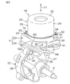
図2および図3は、それぞれ操舵補助機構5の概略斜視図であり、互いに別角度から操舵補助機構5を見た図である。本実施の形態の主に特徴とするところは、上記の制御装置としてのECU12を収容するためのハウジングHを、図2および図3に示すように、互いに接触する(例えば互いの端面を突き合わせた状態、或いは互いの端部を嵌合させた状態である)第1のハウジング23および第2のハウジング24によって構成した点にある。   2 and 3 are schematic perspective views of the steering assist mechanism 5, respectively, and are views of the steering assist mechanism 5 viewed from different angles. The main feature of the present embodiment is that the housing H for housing the ECU 12 as the control device is in contact with each other as shown in FIGS. 2 and 3 (for example, the end faces of each other are abutted against each other). The state is that the first housing 23 and the second housing 24 are in a state or a state in which the end portions are fitted to each other.

すなわち、ECU12を収容するためのハウジングHを構成する第1のハウジング23および第2のハウジング24は互いに接触しており(直接に係合しており)、両ハウジング23,24の間に、別のハウジングが介在していない。これにより、格段の小型化が図られている。
第1のハウジング23および第2のハウジング24は、一端が開放した概ね四角箱形に形成されている。第1および第2のハウジング23,24の互いの端部は、突き合わされ固定ねじ91により互いに締結されている。
In other words, the first housing 23 and the second housing 24 that constitute the housing H for housing the ECU 12 are in contact with each other (directly engaged), and are separately provided between the housings 23 and 24. No housing is interposed. As a result, a significant reduction in size is achieved.
The first housing 23 and the second housing 24 are formed in a substantially square box shape with one end opened. The end portions of the first and second housings 23 and 24 are abutted and fastened to each other by a fixing screw 91.

一方、電動モータのモータハウジング25は、筒状のモータハウジング本体26と、上記の第1のハウジング23とにより構成されている。具体的には、ECU12を収容するためのハウジングHの一部である第1のハウジング23が、電動モータ12のモータハウジング25の少なくとも一部とは単一の材料で一体に形成されている。換言すると、モータハウジング25の少なくとも一部と、ECU12を収容するためのハウジングHの一部とが兼用されている。   On the other hand, the motor housing 25 of the electric motor includes a cylindrical motor housing body 26 and the first housing 23 described above. Specifically, the first housing 23 that is a part of the housing H for housing the ECU 12 is formed integrally with at least a part of the motor housing 25 of the electric motor 12 from a single material. In other words, at least a part of the motor housing 25 and a part of the housing H for housing the ECU 12 are combined.

また、ギヤハウジング22は、ウォーム軸20が収容された筒状の駆動ギヤ収容ハウジング27と、ウォームホイール21が収容された筒状の従動ギヤ収容ハウジング28と、上記の第2のハウジング24とにより構成されている。具体的には、ECU12を収容するためのハウジングHの一部である第2のハウジング24が、ギヤハウジング22の駆動ギヤ収容ハウジング27および従動ギヤ収容ハウジング28とは単一の材料で一体に形成されている。換言すると、ギヤハウジング22の一部と、ECU12を収容するためのハウジングHの一部とが兼用されている。   The gear housing 22 includes a cylindrical drive gear housing 27 in which the worm shaft 20 is housed, a cylindrical driven gear housing 28 in which the worm wheel 21 is housed, and the second housing 24 described above. It is configured. Specifically, the second housing 24 that is a part of the housing H for housing the ECU 12 is formed integrally with the drive gear housing 27 and the driven gear housing 28 of the gear housing 22 from a single material. Has been. In other words, a part of the gear housing 22 is also used as a part of the housing H for housing the ECU 12.

第1のハウジング23の側壁としての外周壁92の外周92aには、筒状突起93が突出形成されており、その筒状突起93内には、第1のハウジング23の外部に臨む電気コネクタ94が配置されている。図示していないが、電気コネクタ94には、バッテリーからECU12に電源供給するための端子や、外部からの信号の入、出力用の端子が設けられている。   A cylindrical projection 93 projects from an outer periphery 92 a of the outer peripheral wall 92 as a side wall of the first housing 23, and an electrical connector 94 facing the outside of the first housing 23 is formed in the cylindrical projection 93. Is arranged. Although not shown, the electrical connector 94 is provided with terminals for supplying power from the battery to the ECU 12 and terminals for inputting and outputting signals from the outside.

電動パワーステアリング装置の要部の断面図である図4を参照して、減速機構19(伝達機構)の従動側部材としてのウォームホイール21、および電気コネクタ94は、減速機構19(伝達機構)の駆動側部材としてのウォーム軸20の中心軸線C3を含み且つウォームホイール21の中心軸線21aとは平行な平面Q1に対して、同側に配置されている。   Referring to FIG. 4 which is a cross-sectional view of the main part of the electric power steering apparatus, the worm wheel 21 as the driven member of the speed reduction mechanism 19 (transmission mechanism) and the electrical connector 94 are the same as those of the speed reduction mechanism 19 (transmission mechanism). It is arranged on the same side with respect to a plane Q1 including the central axis C3 of the worm shaft 20 as the drive side member and parallel to the central axis 21a of the worm wheel 21.

この場合、電動モータ18の回転軸37の軸方向X1に沿って見たときに、突出部となる電気コネクタ94および従動ギヤ収容ハウジング28が同側に突出することになる。その結果、実質的な小型化および省スペース化を図ることができ、車両への搭載性が向上する。
また、図3を参照して、電動モータ18の後述する回転軸37の軸方向X1に沿って見たときに、電気コネクタ94および従動ギヤ収容ハウジング28の互いの少なくとも一部が互いに重なり合うレイアウトとされている。これにより、実質的な小型化および省スペース化を図ることができ、車両への搭載性が向上する。
In this case, when viewed along the axial direction X1 of the rotating shaft 37 of the electric motor 18, the electrical connector 94 and the driven gear housing 28 that serve as a projecting portion project to the same side. As a result, substantial downsizing and space saving can be achieved, and mountability on the vehicle is improved.
Further, with reference to FIG. 3, when viewed along an axial direction X1 of a rotating shaft 37 (to be described later) of the electric motor 18, the electrical connector 94 and the driven gear housing 28 have a layout in which at least a part of each other overlaps each other. Has been. Thereby, substantial miniaturization and space saving can be achieved, and the mounting property to the vehicle is improved.

また、回転軸37の軸方向X1に沿って見たときに、電気コネクタ94およびセンサハウジング35の互いの少なくとも一部が互いに重なり合うレイアウトとされている。これにより、実質的な小型化および省スペース化を図ることができ、車両への搭載性が向上する。
モータハウジング25の第1のハウジング23は、例えばアルミニウム合金(例えば鋳造品、冷間鍛造品)により形成され、操舵補助機構5の軽量化が図られている。また、駆動ギヤ収容ハウジング27、従動ギヤ収容ハウジング28および第2のハウジング24で構成されるギヤハウジング22は、例えばアルミニウム合金(例えば鋳造品、冷間鍛造品)により形成され、操舵補助機構5の軽量化が図られている。また、モータハウジング25のモータハウジング本体26には、例えば非磁性の板金が用いられている。
Further, when viewed along the axial direction X1 of the rotary shaft 37, the electrical connector 94 and the sensor housing 35 have a layout in which at least a part of each other overlaps each other. Thereby, substantial miniaturization and space saving can be achieved, and the mounting property to the vehicle is improved.
The first housing 23 of the motor housing 25 is formed of, for example, an aluminum alloy (for example, a cast product or a cold forging product), and the steering assist mechanism 5 is reduced in weight. The gear housing 22 including the drive gear housing 27, the driven gear housing 28, and the second housing 24 is formed of, for example, an aluminum alloy (for example, a cast product or a cold forging product). The weight is reduced. Further, for example, a non-magnetic sheet metal is used for the motor housing body 26 of the motor housing 25.

モータハウジング本体26は、円筒状の周壁29と、周壁29の一端を閉塞する底壁30と、周壁29の他端からその径方向外方に張り出した環状のフランジ31とを含む。
環状のフランジ31の周方向の一部から径方向外方に張り出したブラケット32が設けられている。そのブラケット32のねじ挿通孔33に挿通された固定ねじ34が、第1のハウジング23のねじ孔にねじ込まれることにより、モータハウジング本体26と第1のハウジング23とが一体に固定されている。上記のねじ挿通孔33は、モータハウジング本体26の周方向に延びる長孔に形成されているので、第1のハウジング23に対して、モータハウジング本体26の周方向位置を調整可能となっている。
The motor housing body 26 includes a cylindrical peripheral wall 29, a bottom wall 30 that closes one end of the peripheral wall 29, and an annular flange 31 that protrudes radially outward from the other end of the peripheral wall 29.
A bracket 32 projecting radially outward from a part of the annular flange 31 in the circumferential direction is provided. The motor housing body 26 and the first housing 23 are integrally fixed by screwing the fixing screw 34 inserted through the screw insertion hole 33 of the bracket 32 into the screw hole of the first housing 23. Since the screw insertion hole 33 is formed as a long hole extending in the circumferential direction of the motor housing body 26, the circumferential position of the motor housing body 26 can be adjusted with respect to the first housing 23. .

また、ECU12を収容するためのハウジングHを構成する第1のハウジング23および第2のハウジング24は、固定ねじ91を用いて互いに固定されている。
ギヤハウジング22の従動ギヤ収容ハウジング28には、トルクセンサ11が収容された筒状のセンサハウジング35が連結されており、従動ギヤ収容ハウジング28およびセンサハウジング35は、固定ねじ36を用いて互いに固定されている。ステアリングシャフト6が、筒状の従動ギヤ収容ハウジング28およびセンサハウジング35内に挿通されている。
Further, the first housing 23 and the second housing 24 that constitute the housing H for housing the ECU 12 are fixed to each other using a fixing screw 91.
A cylindrical sensor housing 35 in which the torque sensor 11 is accommodated is connected to the driven gear accommodating housing 28 of the gear housing 22, and the driven gear accommodating housing 28 and the sensor housing 35 are fixed to each other using a fixing screw 36. Has been. The steering shaft 6 is inserted into the cylindrical driven gear housing 28 and the sensor housing 35.

図4を参照して、電動モータ18のモータハウジング25である第1のハウジング23とこの第1のハウジング23に接触する第2のハウジング24とによって、制御装置としてのECU12を収容する収容室100が形成されている。第1のハウジング23および第2のハウジング24の互いの端面が突き合わされており、両端面間が環状のシール部材95によって封止されている。   Referring to FIG. 4, a housing chamber 100 that houses ECU 12 as a control device by first housing 23 that is motor housing 25 of electric motor 18 and second housing 24 that is in contact with first housing 23. Is formed. The end surfaces of the first housing 23 and the second housing 24 are abutted with each other, and the both end surfaces are sealed with an annular seal member 95.

シール部材95は、図6に示すように、第1および第2のハウジング23,24の何れか一方、例えば第2のハウジング24の端面98に形成された環状溝99に収容され、他方の、例えば第1のハウジング23の端面(フランジ88の端面88aに相当)に接触している。シール部材95としては、例えばOリングを用いることができる。
再び図4を参照して、第1のハウジング23は、収容室100の一部を区画する第1の内壁面101を含み、第2のハウジング24は収容室100の一部を区画する第2の内壁面102を含み、これら第1の内壁面101および第2の内壁面102は、電動モータ18の回転軸37の軸方向X1に対向している。
As shown in FIG. 6, the seal member 95 is accommodated in one of the first and second housings 23, 24, for example, an annular groove 99 formed in the end surface 98 of the second housing 24, and the other, For example, it contacts the end surface of the first housing 23 (corresponding to the end surface 88a of the flange 88). As the seal member 95, for example, an O-ring can be used.
Referring again to FIG. 4, the first housing 23 includes a first inner wall surface 101 that defines a part of the storage chamber 100, and the second housing 24 is a second that partitions a part of the storage chamber 100. The first inner wall surface 101 and the second inner wall surface 102 are opposed to the axial direction X1 of the rotating shaft 37 of the electric motor 18.

また、第2のハウジング24の第2の内壁面102は、環状平面により構成されており、その環状平面は、電動モータ18の回転軸37の中心軸線C1または上記中心軸線C1の延長線C2(通例、ウォーム軸20の中心軸線C3に一致)とは直交し且つ上記中心軸線C1または上記延長線C2の回りを取り囲んでいる。
第2の内壁面102のなす環状平面の延長面P1が、ステアリングシャフト6を取り囲む筒状部としての従動ギヤ収容ハウジング28の外周面28aの主要部のなす円筒面P2と図4のように交差するか、または接する状態にある。具体的には、従動ギヤ収容ハウジング28は、ステアリングシャフト6が嵌合するウォームホイール21を取り囲んでいる。
In addition, the second inner wall surface 102 of the second housing 24 is configured by an annular plane, and the annular plane is the central axis C1 of the rotating shaft 37 of the electric motor 18 or an extension line C2 ( Usually, it is orthogonal to the central axis C3 of the worm shaft 20 and surrounds the central axis C1 or the extension line C2.
The extended surface P1 of the annular plane formed by the second inner wall surface 102 intersects the cylindrical surface P2 formed by the main part of the outer peripheral surface 28a of the driven gear housing 28 as a cylindrical portion surrounding the steering shaft 6 as shown in FIG. You are in or are in contact. Specifically, the driven gear housing 28 surrounds the worm wheel 21 to which the steering shaft 6 is fitted.

また、制御装置としてのECU12は、回転軸37の中心軸線C1または延長線C2の回りに配置されている。
電動モータ18の回転軸37およびウォーム軸20が同軸上に並べて配置されており、回転軸37およびウォーム軸20は、互いの間に介在する継手38を介して同軸的に動力伝達可能に連結されている。継手38は、電動モータ18の回転軸37と同行回転する環状の入力部材39と、ウォーム軸20と同行回転する環状の出力部材40と、入力部材39および出力部材40の間に介在し入力部材39および出力部材40を動力伝達可能に連結する環状の弾性部材41とを有している。
Further, the ECU 12 as the control device is disposed around the central axis C1 or the extension line C2 of the rotating shaft 37.
A rotating shaft 37 and a worm shaft 20 of the electric motor 18 are arranged side by side on the same axis, and the rotating shaft 37 and the worm shaft 20 are coaxially connected to each other via a joint 38 interposed therebetween so that power can be transmitted. ing. The joint 38 is interposed between the input member 39 and the output member 40, the annular input member 39 that rotates together with the rotating shaft 37 of the electric motor 18, the annular output member 40 that rotates along with the worm shaft 20, and the input member 40. 39 and an output elastic member 41 for connecting the output member 40 so that power can be transmitted.

ウォーム軸20は、ギヤハウジング22の駆動ギヤ収容ハウジング27の駆動ギヤ収容孔42に収容されている。ウォーム軸20は第1の端部20aおよび第2の端部20bを有しており、ウォーム軸20の軸方向の中間部にウォーム20cが形成されている。
ウォーム軸20の第1の端部20aは、駆動ギヤ収容孔42の一端(電動モータ18側の端部)の内周の軸受保持部44に保持された第1の軸受45によって、回転可能に支持されている。ウォーム軸20の第2の端部20bは、駆動ギヤ収容孔42の他端の内周の軸受保持部46に保持された第2の軸受47によって、回転可能に支持されている。
The worm shaft 20 is accommodated in the drive gear accommodation hole 42 of the drive gear accommodation housing 27 of the gear housing 22. The worm shaft 20 has a first end portion 20 a and a second end portion 20 b, and a worm 20 c is formed at an intermediate portion in the axial direction of the worm shaft 20.
The first end portion 20a of the worm shaft 20 can be rotated by a first bearing 45 held by a bearing holding portion 44 on the inner periphery of one end (end portion on the electric motor 18 side) of the drive gear accommodation hole 42. It is supported. The second end portion 20 b of the worm shaft 20 is rotatably supported by a second bearing 47 held by an inner peripheral bearing holding portion 46 at the other end of the drive gear accommodation hole 42.

第1の軸受45は、内輪48と、外輪49と、内輪48および外輪49の間に介在する複数の転動体50とを有する転がり軸受からなる。内輪48は、ウォーム軸20の第1の端部20aに同行回転可能に保持されている。内輪48の一方の端面は、ウォーム軸20の外周に設けられた位置決め段部に当接している。ウォーム軸20の第1の端部20aには、小径の突軸51が延設されており、その突軸51には、継手38の出力部材40が同行回転可能に且つ軸方向移動不能に嵌合されている。出力部材40は内輪48の他方の端面に当接しており、ウォーム軸20の上記位置決め段部と出力部材40の間に、内輪48が挟持されている。これにより、ウォーム軸20に対する内輪45の軸方向移動が規制されている。   The first bearing 45 is a rolling bearing having an inner ring 48, an outer ring 49, and a plurality of rolling elements 50 interposed between the inner ring 48 and the outer ring 49. The inner ring 48 is held by the first end 20a of the worm shaft 20 so as to be able to rotate together. One end face of the inner ring 48 is in contact with a positioning step provided on the outer periphery of the worm shaft 20. A small-diameter protruding shaft 51 is extended from the first end portion 20a of the worm shaft 20, and the output member 40 of the joint 38 is fitted to the protruding shaft 51 so that the output member 40 can rotate together and cannot move in the axial direction. Are combined. The output member 40 is in contact with the other end surface of the inner ring 48, and the inner ring 48 is sandwiched between the positioning step portion of the worm shaft 20 and the output member 40. Thereby, the axial movement of the inner ring 45 relative to the worm shaft 20 is restricted.

外輪49の一方の端面が、駆動ギヤ収容孔42の軸受保持部44の一側に隣接する段部に、所定の隙間を隔てて対向している。また、駆動ギヤ収容孔42の軸受保持部44の他側に隣接するねじ部に、環状の固定部材52がねじ込まれており、固定部材52が外輪49の他方の端面を押圧している。これにより、外輪49の軸方向移動が規制されている。 固定部材52は、外周にねじが形成された筒状の本体52aと、本体52aの一端から径方向内方に延びる内方フランジ52bと、本体52aの他端から径方向外方に延びる外方フランジ52cとを有している。内方フランジ52bが、外輪49の他方の端面を押圧している。また、外方フランジ52cは、ECU12の収容室を区画する第2のハウジング24の第2の内壁面102に押圧されており、これにより、固定部材52の緩み止めが達成されている。   One end surface of the outer ring 49 is opposed to a step portion adjacent to one side of the bearing holding portion 44 of the drive gear accommodation hole 42 with a predetermined gap therebetween. An annular fixing member 52 is screwed into a screw portion adjacent to the other side of the bearing holding portion 44 of the drive gear accommodation hole 42, and the fixing member 52 presses the other end surface of the outer ring 49. Thereby, the axial movement of the outer ring 49 is restricted. The fixing member 52 includes a cylindrical main body 52a having a screw formed on the outer periphery, an inner flange 52b extending radially inward from one end of the main body 52a, and an outer extending radially outward from the other end of the main body 52a. And a flange 52c. The inner flange 52 b presses the other end surface of the outer ring 49. Further, the outer flange 52c is pressed against the second inner wall surface 102 of the second housing 24 that divides the accommodation chamber of the ECU 12, and thereby the locking of the fixing member 52 is achieved.

固定部材52の筒状の本体52a内には、継手38の一部が収容されている。これにより、回転軸37の軸方向X1に関しての、電動パワーステアリング装置1の小型化が達成されている。
第2の軸受47は、内輪53と、外輪54と、内輪53および外輪54の間に介在する複数の転動体55とを有する転がり軸受からなる。内輪53は、ウォーム軸20の第2の端部20bに同行回転可能に保持されている。内輪53の一方の端面は、ウォーム軸20の外周に設けられた位置決め段部に当接している。これにより、ウォーム軸20に対する内輪53の軸方向移動(第1の軸受45側への移動)が規制されている。
A part of the joint 38 is accommodated in the cylindrical main body 52 a of the fixing member 52. Thereby, size reduction of the electric power steering device 1 with respect to the axial direction X1 of the rotating shaft 37 is achieved.
The second bearing 47 is composed of a rolling bearing having an inner ring 53, an outer ring 54, and a plurality of rolling elements 55 interposed between the inner ring 53 and the outer ring 54. The inner ring 53 is held by the second end 20b of the worm shaft 20 so as to be able to rotate together. One end face of the inner ring 53 is in contact with a positioning step provided on the outer periphery of the worm shaft 20. Thereby, the axial movement (movement toward the first bearing 45) of the inner ring 53 with respect to the worm shaft 20 is restricted.

駆動ギヤ収容孔42の軸受保持部46に隣接する、駆動ギヤ収容孔42の入口部に、ねじ部56が形成されており、そのねじ部56に、第1および第2の軸受45,47に一括して予圧を付与するための予圧付与部材57がねじ込まれている。予圧付与部材57は、円板状の本体58を有しており、本体58の外周には、上記ねじ部56に螺合するねじ部59が形成されている。また、本体58の一方の端面に、第2の軸受47の外輪54の一方の端面を押圧する環状凸部60が形成されている。   A screw portion 56 is formed at the entrance portion of the drive gear accommodation hole 42 adjacent to the bearing holding portion 46 of the drive gear accommodation hole 42, and the first and second bearings 45 and 47 are formed in the screw portion 56. A preload application member 57 for applying preload in a lump is screwed in. The preload applying member 57 has a disk-shaped main body 58, and a screw portion 59 that is screwed into the screw portion 56 is formed on the outer periphery of the main body 58. An annular convex portion 60 that presses one end surface of the outer ring 54 of the second bearing 47 is formed on one end surface of the main body 58.

本体58の他方の端面には、当該予圧付与部材57を回動操作するための工具を係合する、例えば断面多角形形状の工具係合孔61が形成されている。また、本体58のねじ部59に螺合されたロックナット62によって、予圧付与部材57が止定されるようになっている。
ウォーム軸20の第1および第2の端部20a,20bを支持する第1および第2の軸受45,47は、何れも公知のシール軸受により構成されている。具体的には、転動体の軸方向X1の両側において、内輪と外輪の間を密封するシール部材62を備えており、そのシール部材62は、内輪または外輪の何れか一方に固定される。また、シール部材62は他方に摺接するリップを有している。
A tool engagement hole 61 having a polygonal cross section, for example, is formed on the other end surface of the main body 58 to engage with a tool for rotating the preload applying member 57. Further, the preload applying member 57 is fixed by a lock nut 62 screwed into the threaded portion 59 of the main body 58.
The first and second bearings 45 and 47 that support the first and second end portions 20a and 20b of the worm shaft 20 are both configured by known seal bearings. Specifically, a seal member 62 that seals between the inner ring and the outer ring is provided on both sides of the rolling element in the axial direction X1, and the seal member 62 is fixed to either the inner ring or the outer ring. Further, the seal member 62 has a lip that is in sliding contact with the other.

ウォーム軸20の両端を支持する第1および第2の軸受45,47がシール軸受により構成されているので、ギヤハウジング22内のグリース等の潤滑剤が、ECU12を収容する収容室100側へ漏れ出ることがない。ただし、収容室100内の密封性を高めるために、例えば、固定部材52の本体52aの外周のねじ部とこれに螺合するねじ部との間に、液体パッキンを介在させてもよい。   Since the first and second bearings 45 and 47 that support both ends of the worm shaft 20 are constituted by seal bearings, lubricant such as grease in the gear housing 22 leaks to the accommodation chamber 100 side in which the ECU 12 is accommodated. I don't get out. However, in order to improve the sealing performance in the storage chamber 100, for example, a liquid packing may be interposed between the screw portion on the outer periphery of the main body 52a of the fixing member 52 and the screw portion screwed into the screw portion.

本実施形態では、電動モータ18としてブラシレスモータが用いられている。電動モータ18は、上記モータハウジング25と、このモータハウジング25内に収容されたロータ64およびステータ65を含む。
ロータ64は、回転軸37の外周に同行回転可能に取り付けられた環状のロータコア66と、ロータコア66の外周に同行回転可能に取り付けられた例えば環状の永久磁石からなるロータマグネット67とを有している。ロータマグネット67には、複数の磁極が周方向に並べて配置されている。これらの磁極は、ロータ64の周方向に関して、N極およびS極が交互に入れ替わるようにされている。
In the present embodiment, a brushless motor is used as the electric motor 18. The electric motor 18 includes the motor housing 25, and a rotor 64 and a stator 65 accommodated in the motor housing 25.
The rotor 64 includes an annular rotor core 66 attached to the outer periphery of the rotary shaft 37 so as to be able to rotate along with the rotor shaft 67, and a rotor magnet 67 made of, for example, an annular permanent magnet attached to the outer periphery of the rotor core 66 so as to be able to rotate along with the rotor. Yes. In the rotor magnet 67, a plurality of magnetic poles are arranged side by side in the circumferential direction. These magnetic poles are configured so that the N pole and the S pole are alternately switched in the circumferential direction of the rotor 64.

ステータ65は、モータハウジング25のモータハウジング本体26の内周に固定されている。ステータ65は、モータハウジング本体26の内周に固定されたステータコア68と、複数のコイル69とを含む。ステータコア68は、環状のヨークと、このヨークの内周から径方向内方へ突出する複数のティースとを含む。各コイル69は対応するティースに巻回されている。   The stator 65 is fixed to the inner periphery of the motor housing body 26 of the motor housing 25. The stator 65 includes a stator core 68 fixed to the inner periphery of the motor housing body 26 and a plurality of coils 69. Stator core 68 includes an annular yoke and a plurality of teeth protruding radially inward from the inner periphery of the yoke. Each coil 69 is wound around a corresponding tooth.

また、モータハウジング25のモータハウジング本体26と第1のハウジング23とにより区画されるモータ室70内には、環状またはC形形状をなすバスバー71が収容されている。各ティースに巻回されたコイル69は、バスバー71と接続されている。バスバー71は、各コイル69と電流印加線との接続部に用いられる導電接続材であり、バスバー71は、各コイル69に、図示しない電力供給源からの電力を配電するための配電部材として機能する。   A bus bar 71 having an annular shape or a C shape is accommodated in the motor chamber 70 defined by the motor housing main body 26 and the first housing 23 of the motor housing 25. The coil 69 wound around each tooth is connected to the bus bar 71. The bus bar 71 is a conductive connection material used for a connection portion between each coil 69 and the current application line, and the bus bar 71 functions as a power distribution member for distributing power from a power supply source (not shown) to each coil 69. To do.

また、モータハウジング25のモータハウジング本体26と第1のハウジング23とにより区画されるモータ室70内には、ロータ64の回転位置を検出するための回転位置検出装置72が収容されている。回転位置検出装置72は、第1のハウジング23に固定されたステータ73と、回転軸37とは同行回転可能に取り付けられたロータ74とを有している。回転位置検出装置72としては、例えばレゾルバを用いることができる。また、ホール素子を用いることもできる。   A rotation position detection device 72 for detecting the rotation position of the rotor 64 is accommodated in the motor chamber 70 defined by the motor housing main body 26 and the first housing 23 of the motor housing 25. The rotational position detection device 72 has a stator 73 fixed to the first housing 23 and a rotor 74 attached to the rotational shaft 37 so as to be able to rotate together. As the rotational position detecting device 72, for example, a resolver can be used. A Hall element can also be used.

回転位置検出装置72は、電動モータ18の回転軸37の軸方向X1に関して電動モータ18のロータ64のロータコア66と、第2のハウジング24との間に配置されていればよい。したがって、本実施の形態のように、モータ室70内に配置されていてもよいし、ECU12の収容室100を区画する第1のハウジング23の中央に設けられた後述する筒状部89内に配置されていてもよい。   The rotational position detection device 72 may be disposed between the rotor core 66 of the rotor 64 of the electric motor 18 and the second housing 24 with respect to the axial direction X1 of the rotation shaft 37 of the electric motor 18. Therefore, as in the present embodiment, it may be arranged in the motor chamber 70, or in a cylindrical portion 89 (described later) provided in the center of the first housing 23 that defines the storage chamber 100 of the ECU 12. It may be arranged.

また、図4を参照して、回転軸37は、モータハウジング25の一部とECU12を収容するハウジングの一部とを兼用する第1のハウジング23によって保持された第3の軸受75および第4の軸受76によって、回転可能に支持されている。第3および第4の軸受75,76は、第1および第2の軸受45,47と同じ構成のシール軸受により構成されている。   Referring to FIG. 4, the rotary shaft 37 includes third and fourth bearings 75 and 4 held by the first housing 23 that serves as both a part of the motor housing 25 and a part of the housing that houses the ECU 12. The bearing 76 is rotatably supported. The third and fourth bearings 75 and 76 are constituted by seal bearings having the same configuration as the first and second bearings 45 and 47.

ECU12の収容室100を区画するハウジングHの一部である第1のハウジング23は、収容室100とモータ室70とを仕切る仕切り壁77を底壁として含んでいる。この仕切り壁77に、上記第1の内壁面101が設けられている。仕切り壁77の外周の近傍からモータハウジング本体26側に向かって筒状突起104が延びており、その筒状突起104の外周に、モータハウジング本体26の一端が嵌合されている。   The first housing 23, which is a part of the housing H that partitions the storage chamber 100 of the ECU 12, includes a partition wall 77 that partitions the storage chamber 100 and the motor chamber 70 as a bottom wall. The partition wall 77 is provided with the first inner wall surface 101. A cylindrical projection 104 extends from the vicinity of the outer periphery of the partition wall 77 toward the motor housing body 26, and one end of the motor housing body 26 is fitted to the outer periphery of the cylindrical projection 104.

また、仕切り壁77は、上記の第3の軸受75の外輪を保持するための保持孔105を有している。仕切り壁77からモータハウジング本体26側に向けて延びる筒状突起106が形成されている。筒状突起106は上記保持孔105とは同軸的に形成されている。筒状突起106は、モータハウジング本体26に係合する上記の筒状突起104よりも小径に形成されている。この筒状突起106の内周には、回転位置検出装置72のステータ73が固定されている。   The partition wall 77 has a holding hole 105 for holding the outer ring of the third bearing 75. A cylindrical projection 106 extending from the partition wall 77 toward the motor housing body 26 is formed. The cylindrical protrusion 106 is formed coaxially with the holding hole 105. The cylindrical projection 106 is formed with a smaller diameter than the cylindrical projection 104 that engages with the motor housing body 26. A stator 73 of the rotational position detecting device 72 is fixed to the inner periphery of the cylindrical protrusion 106.

また、仕切り壁77から第2のハウジング24側に向けて延びる筒状部89が形成されている。筒状部89は上記の保持孔105とは同軸的に形成されている。筒状部89内の内周には、上記の第4の軸受76の外輪が保持されている。筒状部89の一端には、径方向内方に延びる環状フランジ107が延設されており、第4の軸受76の外輪の一端が環状フランジ107に当接することにより、筒状部89に対する第4の軸受76の外輪の軸方向移動が規制されている。   Further, a cylindrical portion 89 extending from the partition wall 77 toward the second housing 24 is formed. The cylindrical portion 89 is formed coaxially with the holding hole 105. The outer ring of the fourth bearing 76 is held on the inner periphery of the cylindrical portion 89. An annular flange 107 extending radially inward is extended at one end of the cylindrical portion 89, and one end of the outer ring of the fourth bearing 76 abuts on the annular flange 107, so The axial movement of the outer ring of the fourth bearing 76 is restricted.

一方、第4の軸受76の内輪は、回転軸37の外周に形成された環状の位置決め段部と、継手38の入力部材39の端面との間に挟持されており、これにより、回転軸37に対する第4の軸受76の内輪の軸方向移動が規制されている。
収容室100には、ECU12の一部を構成するパワー基板78および制御基板79が収容され保持されている。パワー基板78には、電動モータ18を駆動するためのパワー回路の少なくとも一部(例えばFETなどのスイッチング素子)が実装されている。上記の各コイル69と接続されたバスバー71は、第1のハウジング23の上記仕切り壁77を挿通して収容室100内に進入するバスバー端子80を介して、パワー基板78に接続されている。
On the other hand, the inner ring of the fourth bearing 76 is sandwiched between an annular positioning step formed on the outer periphery of the rotating shaft 37 and the end face of the input member 39 of the joint 38, whereby the rotating shaft 37. The axial movement of the inner ring of the fourth bearing 76 is restricted.
In the accommodation chamber 100, a power board 78 and a control board 79 that constitute a part of the ECU 12 are accommodated and held. On the power board 78, at least a part of a power circuit (for example, a switching element such as an FET) for driving the electric motor 18 is mounted. The bus bar 71 connected to each coil 69 is connected to the power board 78 via a bus bar terminal 80 that passes through the partition wall 77 of the first housing 23 and enters the housing chamber 100.

また、回転位置検出装置72が、第1のハウジング23の仕切り壁77を挿通して収容室100内に進入するバスバー端子81を介して、制御基板79に接続されている。
収容室100内において、パワー回路が実装されたパワー基板78は、第1の内壁面101および第2の内壁面102のうち第1の内壁面101に相対的に近接して配置されている。すなわち、上記の仕切り壁77は、電動モータ18の回転軸37の軸方向X1に関しての厚みt1が相対的に厚い厚肉部77aと相対的に薄い薄肉部77bとを含んでいる。厚肉部77aは、収容室100内に突出するように設けられている。
In addition, the rotational position detection device 72 is connected to the control board 79 via a bus bar terminal 81 that passes through the partition wall 77 of the first housing 23 and enters the storage chamber 100.
In the storage chamber 100, the power board 78 on which the power circuit is mounted is disposed relatively close to the first inner wall surface 101 among the first inner wall surface 101 and the second inner wall surface 102. That is, the partition wall 77 includes a thick portion 77a and a relatively thin portion 77b that have a relatively thick thickness t1 in the axial direction X1 of the rotating shaft 37 of the electric motor 18. The thick portion 77a is provided so as to protrude into the storage chamber 100.

上記のパワー基板78は、厚肉部77aにおける第1の内壁面101に近接して或いは本実施の形態のように接触して配置されている。具体的には、第1の内壁面101において、厚肉部77aの部分が、パワー基板78を受ける座部103となっている。
本実施の形態では、パワー基板78は厚肉部77aにおける第1の内壁面101に対して熱伝導可能に接触しており、上記の厚肉部77aは、パワー基板78の熱を逃がすためのヒートシンクとして機能している。
The power board 78 is arranged close to or in contact with the first inner wall surface 101 in the thick portion 77a. Specifically, in the first inner wall surface 101, the thick portion 77 a is a seat portion 103 that receives the power board 78.
In the present embodiment, the power substrate 78 is in contact with the first inner wall surface 101 in the thick portion 77a so as to be capable of conducting heat, and the thick portion 77a is for releasing the heat of the power substrate 78. It functions as a heat sink.

継手38の入力部材39は、電動モータ18の回転軸37の端部に同行回転可能に嵌合する筒状部39aを有しており、制御基板79は、入力部材39の筒状部39aの周囲に配置されている。具体的には、制御基板79の中央の挿通孔79aに、筒状部39aが挿通されている。
制御基板79は、電動モータ18の回転軸37の軸方向X1に関して、第2のハウジング24の第2の内壁面102とパワー基板78との間に配置されている。パワー基板78および制御基板79は、電動モータ18の回転軸37の軸方向X1に関して所定の間隔を隔てて配置されている。また、電動モータ18の回転軸37の中心軸線C1に沿う方向に関して、制御基板79および継手38の互いの少なくとも一部が重なるようにレイアウトされている。
The input member 39 of the joint 38 has a cylindrical portion 39 a that is fitted to the end portion of the rotating shaft 37 of the electric motor 18 so as to be able to rotate together. The control board 79 is formed of the cylindrical portion 39 a of the input member 39. It is arranged around. Specifically, the cylindrical portion 39 a is inserted through the insertion hole 79 a in the center of the control board 79.
The control board 79 is disposed between the second inner wall surface 102 of the second housing 24 and the power board 78 with respect to the axial direction X1 of the rotating shaft 37 of the electric motor 18. The power board 78 and the control board 79 are arranged at a predetermined interval with respect to the axial direction X1 of the rotating shaft 37 of the electric motor 18. Further, the control board 79 and the joint 38 are laid out so that at least a part of each other overlaps in the direction along the central axis C1 of the rotating shaft 37 of the electric motor 18.

収容室100内において、第1のハウジング23の仕切り壁77の薄肉部77bと制御基板79との間に形成される収容空間S1は、電動モータ18の回転軸37の軸方向X1に関して、十分な高さを有している。図4では図示していないが、この収容空間S1には、後述する図5に示す複数のコンデンサ85やリレー86等の比較的大型で背の高い部品が収容されるようになっており、収容室100内の空間の有効利用が図られている。   In the accommodation chamber 100, the accommodation space S <b> 1 formed between the thin wall portion 77 b of the partition wall 77 of the first housing 23 and the control board 79 is sufficient with respect to the axial direction X <b> 1 of the rotating shaft 37 of the electric motor 18. Has a height. Although not shown in FIG. 4, the housing space S1 accommodates relatively large and tall parts such as a plurality of capacitors 85 and relays 86 shown in FIG. The space in the room 100 is effectively used.

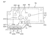
次いで、分解斜視図である図5を参照して、上記のパワー基板78には、電動モータ18を駆動するためのモータ駆動回路としてのパワー回路82が実装されている。図5および図7を参照して、パワー基板78に実装されるパワー回路82には、スイッチング素子としての複数のFET83(電解効果型トランジスタ)と、FET83によるスイッチングノイズを低減するための複数のスナバ回路200とが含まれている。パワー基板78は、片面に回路が実装されたモータ制御装置である積層回路基板を構成している。パワー基板78は、基板本体301と、ヒートシンクとしての厚肉部77aに対して面接触する例えばアルミニウム板からなる高熱伝導板としての金属ベース302とを含んでいる。   Next, referring to FIG. 5, which is an exploded perspective view, a power circuit 82 is mounted on the power board 78 as a motor drive circuit for driving the electric motor 18. Referring to FIGS. 5 and 7, power circuit 82 mounted on power board 78 includes a plurality of FETs 83 (electrolytic effect type transistors) as switching elements and a plurality of snubbers for reducing switching noise caused by FETs 83. A circuit 200 is included. The power board 78 constitutes a laminated circuit board which is a motor control device having a circuit mounted on one side. The power substrate 78 includes a substrate main body 301 and a metal base 302 as a high thermal conductive plate made of, for example, an aluminum plate that is in surface contact with the thick portion 77a as a heat sink.

また、上記の制御基板79には、電動モータ18を駆動するパワー回路82を制御するための制御回路84が実装されている。制御基板79に実装された制御回路84は、電動モータ18の回転軸37の中心軸線C1(または中心軸線C1の延長線C2)の回りに配置されている。制御回路84には、パワー回路82の各FET83を制御するドライバと、このドライバを制御するCPUとが含まれている。   A control circuit 84 for controlling the power circuit 82 that drives the electric motor 18 is mounted on the control board 79. The control circuit 84 mounted on the control board 79 is arranged around the central axis C1 of the rotating shaft 37 of the electric motor 18 (or an extension line C2 of the central axis C1). The control circuit 84 includes a driver that controls each FET 83 of the power circuit 82 and a CPU that controls the driver.

また、ECU12は、上述した複数のコンデンサ85や、必要に応じて電動モータ18に流れる電流を遮断するためのリレー86、その他の非発熱要素を有している。コンデンサ85は、電動モータ18への電力ラインに配置され、電動モータ18に流れる電流のリップルを除去する平滑用の電解コンデンサである。通例、この種のコンデンサ85は、大容量であり大型である。非発熱要素としてのコンデンサ85およびリレー86等は、環状の合成樹脂製のホルダ120によって支持されたサブアセンブリSAを構成しており、第1のハウジング23に対して一括して取り付け操作が行えるようになっている。   Further, the ECU 12 includes the plurality of capacitors 85 described above, a relay 86 for cutting off the current flowing through the electric motor 18 as necessary, and other non-heating elements. The capacitor 85 is a smoothing electrolytic capacitor that is disposed in a power line to the electric motor 18 and removes a ripple of a current flowing through the electric motor 18. Typically, this type of capacitor 85 is large in capacity and large. The capacitor 85, the relay 86, and the like as non-heat generating elements constitute a subassembly SA supported by an annular synthetic resin holder 120, and can be collectively attached to the first housing 23. It has become.

各コンデンサ85は、ホルダ120に設けられた例えばアングル状の保持部121に、横倒し状態で保持されている。すなわち、大型のコンデンサ85の長手方向を上記中心軸線C1に平行な方向に対して直交する方向に向けて配置することにより、上記中心軸線C1に沿う方向に関しての、収容室100の小型化が図られている。
第1のハウジング23は、一端が開放した概ね四角箱型の部材である。具体的には、第1のハウジング23は、一端が開放した概ね四角箱型の本体87を備えている。本体87は、概ね四角環状をなす外周壁92と、外周壁92の一端から径方向外方に向けて張り出した四角環状のフランジ88と、底壁としての上記仕切り壁77とを有している。
Each capacitor 85 is held in a laid-down state by, for example, an angle-shaped holding portion 121 provided in the holder 120. That is, by arranging the longitudinal direction of the large capacitor 85 in a direction perpendicular to the direction parallel to the central axis C1, the storage chamber 100 can be downsized in the direction along the central axis C1. It has been.
The first housing 23 is a substantially square box-shaped member having one end opened. Specifically, the first housing 23 includes a generally rectangular box-shaped main body 87 having one end opened. The main body 87 has a substantially annular outer peripheral wall 92, a rectangular annular flange 88 projecting radially outward from one end of the outer peripheral wall 92, and the partition wall 77 as a bottom wall. .

収容室100内において、仕切り壁77の中央部には、本体87の開放側(第2のハウジング24側)に向かって延びる筒状部89が形成されている。外周壁92は、仕切り壁77の外周縁から延設されており、筒状部89を取り囲んでいる。本体87および筒状部89は、単一の部材で一体に形成されている。
フランジ88の端面88a(図5では、上面)は、平面にされている。この端面88aに上記のシール部材95が接触することになる。また、フランジ88は、径方向外方に向かって突出する複数(本実施の形態では一対)のブラケット状の取付部96を有している。各取付部96には、当該取付部96をその厚み方向に貫通するねじ挿通孔97が形成されている。各ねじ挿通孔97には、第1および第2のハウジング23,24を締結するための上記の固定ねじ91が挿通される。
In the storage chamber 100, a cylindrical portion 89 extending toward the open side (the second housing 24 side) of the main body 87 is formed at the central portion of the partition wall 77. The outer peripheral wall 92 extends from the outer peripheral edge of the partition wall 77 and surrounds the tubular portion 89. The main body 87 and the cylindrical portion 89 are integrally formed of a single member.
An end surface 88a (the upper surface in FIG. 5) of the flange 88 is flat. The sealing member 95 comes into contact with the end surface 88a. Further, the flange 88 has a plurality of (a pair in the present embodiment) bracket-shaped attachment portions 96 protruding outward in the radial direction. Each attachment portion 96 is formed with a screw insertion hole 97 that penetrates the attachment portion 96 in the thickness direction. The fixing screws 91 for fastening the first and second housings 23 and 24 are inserted through the screw insertion holes 97.

四角環状をなす外周壁92は、4つの側壁111〜114を有しており、対向する一対の側壁112,114の端部に、上記取付部96が延設されている。また、上記ヒートシンクとして機能する、仕切り壁77の厚肉部77aは、上記取付部96が延設された1つの側壁112の内面に連続して形成されている。
第1の内壁面101のうち、厚肉部77aにおける部分が、パワー基板78を受ける座部103を構成している。座部103は、発熱要素としてのFET83を有するパワー基板78に、熱伝導可能に接触している。発熱要素の熱は、パワー基板78から、ヒートシンクを構成する厚肉部77aおよび取付部96を介して、第2のハウジング24とは一体のギヤハウジング22側へ逃がされる。
The outer peripheral wall 92 having a quadrangular annular shape has four side walls 111 to 114, and the mounting portion 96 is extended at the ends of a pair of opposing side walls 112 and 114. Further, the thick portion 77a of the partition wall 77 that functions as the heat sink is formed continuously on the inner surface of one side wall 112 on which the mounting portion 96 is extended.
Of the first inner wall surface 101, a portion in the thick portion 77 a constitutes a seat portion 103 that receives the power board 78. The seat portion 103 is in contact with a power substrate 78 having an FET 83 as a heat generating element so as to allow heat conduction. The heat of the heat generating element is released from the power board 78 to the side of the gear housing 22 integrated with the second housing 24 through the thick portion 77a and the mounting portion 96 constituting the heat sink.

固定ねじ91による締結に用いられる取付部96では、フランジ88の他の部分と比較して、第2のハウジング24に対する接触面積が広くなっている。その取付部96が設けられた側壁112に連続して、熱容量の大きいヒートシンクとなる厚肉部77aを設けてある。
パワー基板78が、座部103に取り付けられた後、コンデンサ85、リレー86およびホルダ120を含むサブアセンブリSAが取り付けられる。このとき、環状のホルダ120の中央部が大きく開放されているので、パワー基板78の表面の大部分は、ホルダ120により覆われることなく、開放する状態になる。これにより、パワー基板78の表面に隣接する十分な放熱スペースが確保されるようにしてある。
In the attachment portion 96 used for fastening by the fixing screw 91, the contact area with respect to the second housing 24 is wide as compared with other portions of the flange 88. A thick wall 77a serving as a heat sink having a large heat capacity is provided continuously to the side wall 112 provided with the mounting portion 96.
After the power board 78 is attached to the seat 103, the subassembly SA including the capacitor 85, the relay 86, and the holder 120 is attached. At this time, since the central portion of the annular holder 120 is largely open, most of the surface of the power board 78 is not covered by the holder 120 and is open. Thereby, a sufficient heat radiation space adjacent to the surface of the power board 78 is ensured.

図8は、パワー基板78が第1のハウジング23の厚肉部77aに固定された状態を示す要部の断面図である。図8を参照して、厚肉部77aは、基板設置部材として設けられている。この厚肉部77aの一側面303は、軸線C1とは直交して平坦に延びている。この一側面303に、パワー基板78が設置されている。
パワー基板78は、基板本体301および金属ベース302と、被覆部材304とを備えている。
FIG. 8 is a cross-sectional view of the main part showing a state in which the power board 78 is fixed to the thick part 77 a of the first housing 23. Referring to FIG. 8, thick portion 77a is provided as a substrate installation member. One side surface 303 of the thick portion 77a extends flatly perpendicular to the axis C1. A power board 78 is installed on the one side surface 303.
The power board 78 includes a board body 301, a metal base 302, and a covering member 304.

基板本体301は、絶縁体からなる絶縁層と、導電体を含む層とを積層してなる。具体的には、基板本体301は、基板本体301の表面層としての第1の層311と、第2の層312と、第3の層313と、第4の層314と、第5の層315と、第6の層316と、基板本体301の裏面層としての第7の層317と、を含んでいる。各上記第1〜第7の層311〜317が、軸線C1に沿う積層方向Dに沿ってこの順に配置されている。   The substrate body 301 is formed by laminating an insulating layer made of an insulator and a layer containing a conductor. Specifically, the substrate body 301 includes a first layer 311, a second layer 312, a third layer 313, a fourth layer 314, and a fifth layer as surface layers of the substrate body 301. 315, a sixth layer 316, and a seventh layer 317 as a back layer of the substrate body 301. The first to seventh layers 311 to 317 are arranged in this order along the stacking direction D along the axis C1.

奇数番目の層としての第1、第3、第5、および第7の層311,313,315,317は、絶縁体からなる絶縁層を構成している。この絶縁体として、基材としての合成樹脂材料に、セラミックの粉末やガラス繊維等の、合成樹脂材料よりも熱伝導率が高い熱伝導材を添加したものを例示することができる。これにより、基板本体301の熱伝導性を高めており、熱抵抗が小さくされている。   The first, third, fifth, and seventh layers 311, 313, 315, and 317 as the odd-numbered layers constitute an insulating layer made of an insulator. As this insulator, what added the heat conductive material higher in heat conductivity than synthetic resin materials, such as a ceramic powder and glass fiber, to the synthetic resin material as a base material can be illustrated. Thereby, the thermal conductivity of the substrate body 301 is increased, and the thermal resistance is reduced.

偶数番目の層としての第2、第4および第6の層312,314,316は、それぞれ、導体を含む層を構成している。
第2の層312は、導体としての導電部312aと、絶縁体としての絶縁部312bとを含んでいる。導電部312aは、銅等の金属を用いて形成されている。絶縁部312bは、上記第1の層311と同様の材料を用いて形成されており、導電部312aを取り囲んでいる。
The second, fourth, and sixth layers 312, 314, and 316 as even-numbered layers each constitute a layer that includes a conductor.
The second layer 312 includes a conductive portion 312a as a conductor and an insulating portion 312b as an insulator. The conductive portion 312a is formed using a metal such as copper. The insulating portion 312b is formed using the same material as that of the first layer 311 and surrounds the conductive portion 312a.

第4の層314は、導体としての導電部314aと、絶縁体としての絶縁部314bとを含んでいる。導電部314aは、導電部312aと同様の材料を用いて形成されている。絶縁部314bは、上記第1の層311と同様の材料を用いて形成されており、導電部314aを取り囲んでいる。
第6の層316は、導体としての導電部316a,316bと、絶縁体としての絶縁部316cとを含んでいる。各導電部316a,316bは、第2の層312の導電部312aと同様の材料を用いて形成されている。絶縁部316cは、上記第1の層311と同様の材料を用いて形成されている。絶縁部316cは、導電部316a,316bが互いに直接接触しないように、これらの導電部316a,316bをそれぞれ取り囲んでいる。
The fourth layer 314 includes a conductive portion 314a as a conductor and an insulating portion 314b as an insulator. The conductive portion 314a is formed using the same material as that of the conductive portion 312a. The insulating portion 314b is formed using the same material as that of the first layer 311 and surrounds the conductive portion 314a.
The sixth layer 316 includes conductive portions 316a and 316b as conductors and an insulating portion 316c as an insulator. Each of the conductive portions 316a and 316b is formed using the same material as that of the conductive portion 312a of the second layer 312. The insulating portion 316c is formed using a material similar to that of the first layer 311. The insulating portion 316c surrounds the conductive portions 316a and 316b so that the conductive portions 316a and 316b do not directly contact each other.

第2の層312の導電部312aの一部と、第6の層316の導電部316aの一部とは、積層方向Dに対向している。また、第4の層314の導電部314aの一部と、第6の層316の導電部316bの一部とは、積層方向Dに対向している。
第1の層311の表面、すなわち、基板本体301の表面301aには、導電部305a,305b,305cがそれぞれ設けられている。各導電部305a,305b,305cは、第2の層312の導電部312aと同様の材料を用いて形成されている。
A part of the conductive part 312 a of the second layer 312 and a part of the conductive part 316 a of the sixth layer 316 are opposed to each other in the stacking direction D. In addition, a part of the conductive part 314 a of the fourth layer 314 and a part of the conductive part 316 b of the sixth layer 316 are opposed to each other in the stacking direction D.
Conductive portions 305a, 305b, and 305c are provided on the surface of the first layer 311, that is, the surface 301a of the substrate body 301, respectively. Each of the conductive portions 305a, 305b, and 305c is formed using the same material as that of the conductive portion 312a of the second layer 312.

導電部305aと、第2の層312の導電部312aと、第6の層316の導電部316aのそれぞれの一部は、積層方向Dに互いに対向している。
導電部305bと、第2の層312の導電部312aのそれぞれの一部は、積層方向Dに互いに対向している。
導電部305cと、第4の層314の導電部314aと、第6の層316の導電部316bのそれぞれの一部は、積層方向Dに互いに対向している。
Each of the conductive portion 305a, the conductive portion 312a of the second layer 312 and the conductive portion 316a of the sixth layer 316 faces each other in the stacking direction D.
A part of each of the conductive portion 305b and the conductive portion 312a of the second layer 312 is opposed to each other in the stacking direction D.
Each of the conductive portion 305c, the conductive portion 314a of the fourth layer 314, and the conductive portion 316b of the sixth layer 316 are opposed to each other in the stacking direction D.

導電部305aの表面には、めっき層306が形成されている。めっき層306は、例えば、ニッケル金めっき(Ni+Auめっき)である。めっき層306の表面には、半田307を用いて、モータ駆動用素子としてのFET83が接合されている。これにより、FET83は、導電部305aに接合されている。すなわち、FET83は、基板本体301にベアチップ実装されている。   A plating layer 306 is formed on the surface of the conductive portion 305a. The plating layer 306 is, for example, nickel gold plating (Ni + Au plating). An FET 83 as a motor driving element is joined to the surface of the plating layer 306 using solder 307. Thereby, the FET 83 is joined to the conductive portion 305a. That is, the FET 83 is bare chip mounted on the substrate body 301.

基板本体301には、基板本体301の放熱性を増すためのビアホール308a〜308gが形成されている。なお、基板本体301のビアホールを総称していうときは、単にビアホール308という。
各ビアホール308a〜308gは、基板本体301のうち、裏面層としての第7の層307以外の層、すなわち、第1〜第6の層311〜316を貫く層間接続孔である。ビアホール308a〜308dは、FET83が実装されている導電部305aに対応して形成されている。ビアホール308eは、導電部305bに対応して形成されている。ビアホール308f,308gは、導電部305cに対応して形成されている。
Via holes 308 a to 308 g for increasing the heat dissipation of the substrate body 301 are formed in the substrate body 301. Note that the via hole of the substrate body 301 is simply referred to as a via hole 308 when collectively referred to.
Each of the via holes 308a to 308g is an interlayer connection hole that penetrates a layer other than the seventh layer 307 as the back surface of the substrate body 301, that is, the first to sixth layers 311 to 316. The via holes 308a to 308d are formed corresponding to the conductive portion 305a on which the FET 83 is mounted. The via hole 308e is formed corresponding to the conductive portion 305b. The via holes 308f and 308g are formed corresponding to the conductive portion 305c.

ビアホール308a〜308dは、それぞれ、導電部305a、第1の層311、第2の層312の導電部312a、第3の層313、第4の層314の絶縁部314b、第5の層315および第6の層316の導電部316aを貫いている。
ビアホール308eは、導電部305b、第1の層311、第2の層312の導電部312a、第3の層313、第4の層314の絶縁部314b、第5の層315、および第6の層316の絶縁部316cを貫いている。
The via holes 308a to 308d include the conductive portion 305a, the first layer 311, the conductive portion 312a of the second layer 312, the third layer 313, the insulating portion 314b of the fourth layer 314, the fifth layer 315, and The conductive portion 316a of the sixth layer 316 is penetrated.
The via hole 308e includes a conductive portion 305b, a first layer 311, a conductive portion 312a of the second layer 312, a third layer 313, an insulating portion 314b of the fourth layer 314, a fifth layer 315, and a sixth layer. The insulating portion 316c of the layer 316 is penetrated.

ビアホール308f,308gは、第1の層311、第2の層312の絶縁部312b、第3の層313、第4の層314の導電部314a、第5の層315、および第6の層316の導電部316bを貫いている。
ビアホール308a〜308dには、それぞれ、銅等の金属製のピン部材309が圧入固定されている。これにより、導電部305a,第2の層312の導電部312aおよび第6の層316の導電部316aは、ピン部材309を介して電気的に接続されている。
The via holes 308 f and 308 g include the first layer 311, the insulating portion 312 b of the second layer 312, the third layer 313, the conductive portion 314 a of the fourth layer 314, the fifth layer 315, and the sixth layer 316. Through the conductive portion 316b.
A pin member 309 made of metal such as copper is press-fitted and fixed in each of the via holes 308a to 308d. As a result, the conductive portion 305a, the conductive portion 312a of the second layer 312 and the conductive portion 316a of the sixth layer 316 are electrically connected via the pin member 309.

ビアホール308eにも同様に、ピン部材309が圧入固定されている。これにより、導電部305b、および第2の層312の導電部312aが電気的に接続されている。
ビアホール308f,308gにも同様に、ピン部材309が圧入固定されている。これにより、導電部305c、第4の層314の導電部314aおよび第6の導電部316bが電気的に接続されている。
Similarly, a pin member 309 is press-fitted and fixed in the via hole 308e. Accordingly, the conductive portion 305b and the conductive portion 312a of the second layer 312 are electrically connected.
Similarly, a pin member 309 is press-fitted and fixed in the via holes 308f and 308g. Thus, the conductive portion 305c, the conductive portion 314a of the fourth layer 314, and the sixth conductive portion 316b are electrically connected.

上記の構成により、各導電部305a,305b,305cからの熱は、対応するピン部材309を介して、第7の層317に伝わり、さらに金属ベース302から第1のハウジング23の厚肉部77aに伝わる。
FET83は、スイッチング素子として機能することから発熱量が多い。このため、FET83が実装される導電部305aに対応して複数のピン部材309が設けられている。これにより、FET83からの熱をより多く厚肉部77aに伝えることができる。
With the above configuration, the heat from each of the conductive portions 305a, 305b, and 305c is transferred to the seventh layer 317 via the corresponding pin member 309, and further from the metal base 302 to the thick portion 77a of the first housing 23. It is transmitted to.
Since the FET 83 functions as a switching element, it generates a large amount of heat. Therefore, a plurality of pin members 309 are provided corresponding to the conductive portion 305a on which the FET 83 is mounted. Thereby, more heat from the FET 83 can be transmitted to the thick portion 77a.

また、各ピン部材309が第7の層317を貫通していないことから、各ピン部材309が金属ベース302に接触することを防止でき、両者が電気的に接続されることを防止できる。
基板本体301において、第1の層311がこの基板本体301の表面301aを形成しており、第7の層317がこの基板本体301の裏面301bを形成している。これらの表面301aおよび裏面301bは、積層方向Dに相対向している。また、基板本体301において、第1〜第7の層311〜317が協働して、基板本体301の外側面301cを構成している。外側面301cは、全体として環状をなしている。
In addition, since each pin member 309 does not penetrate the seventh layer 317, it is possible to prevent each pin member 309 from contacting the metal base 302 and to prevent both from being electrically connected.
In the substrate body 301, the first layer 311 forms the front surface 301 a of the substrate body 301, and the seventh layer 317 forms the back surface 301 b of the substrate body 301. These front surface 301a and back surface 301b are opposed to each other in the stacking direction D. In the substrate main body 301, the first to seventh layers 311 to 317 cooperate to constitute the outer surface 301 c of the substrate main body 301. The outer side surface 301c has an annular shape as a whole.

基板本体301は、後述するように、絶縁体と導体を含む層とを圧接して形成された板状の製造中間体を打ち抜いて形成したものである。したがって、基板本体301の外側面301cに、基板本体301を構成する樹脂やガラス繊維やセラミック等が粉塵(異物)として付着している場合がある。
本実施の形態の特徴の1つは、この外側面301cの全部を被覆部材304で覆うことで、基板本体301の外側面301cからの異物が飛散することを防止している点にある。
As will be described later, the substrate body 301 is formed by punching a plate-shaped manufacturing intermediate formed by pressing an insulator and a layer containing a conductor. Therefore, the resin, glass fiber, ceramic, or the like constituting the substrate body 301 may adhere to the outer surface 301c of the substrate body 301 as dust (foreign matter).
One of the features of this embodiment is that the outer surface 301c is entirely covered with a covering member 304, thereby preventing foreign matter from scattering from the outer surface 301c of the substrate body 301.

被覆部材304は、基板本体301の外側面301cに所定の材料をコーティングすることにより薄膜状に形成されている。この被覆部材304を構成する材料として、ポリイミド樹脂(PI)、エポキシ樹脂(EP)およびシリコン樹脂(SI)を例示することができる。被覆部材304の外側面304aは、基板本体301の外側面301cと平行な平滑な面に形成されている。   The covering member 304 is formed into a thin film by coating a predetermined material on the outer side surface 301 c of the substrate body 301. Examples of the material constituting the covering member 304 include polyimide resin (PI), epoxy resin (EP), and silicon resin (SI). The outer surface 304 a of the covering member 304 is formed as a smooth surface parallel to the outer surface 301 c of the substrate body 301.

金属ベース302は、ヒートシンクとして設けられており、積層方向Dに沿って見たとき、基板本体301と合致する形状に形成されている。金属ベース302は、前述したように、アルミニウム合金等の熱伝導性に優れた材料を用いて形成されている。この金属ベース302は、積層方向Dに対向する表面302aおよび裏面302bを含んでいる。これらの表面302aおよび裏面302bは、互いに平行である。金属ベース302の表面302aは、基板本体301の裏面301bに接着剤等を用いて固定されており、両者が全面的に面接触している。   The metal base 302 is provided as a heat sink and is formed in a shape that matches the substrate body 301 when viewed along the stacking direction D. As described above, the metal base 302 is formed using a material having excellent thermal conductivity such as an aluminum alloy. The metal base 302 includes a front surface 302 a and a back surface 302 b that face each other in the stacking direction D. These front surface 302a and back surface 302b are parallel to each other. The front surface 302a of the metal base 302 is fixed to the back surface 301b of the substrate body 301 using an adhesive or the like, and both are in surface contact with each other.

金属ベース302の裏面302bは、その全部が、厚肉部77aの一側面303に面接触している。これにより、基板本体301から金属ベース302に伝わった熱を、厚肉部77aに十分に逃がすことができる。
金属ベース302に関連して、位置決め部材318,319が設けられている。各位置決め部材318,319は、パワー基板78を第1のハウジング23の厚肉部77aに対して精度良く位置決めするためのものであり、絶縁体を用いて形成されている。
The entire back surface 302b of the metal base 302 is in surface contact with one side surface 303 of the thick portion 77a. Thereby, the heat transmitted from the substrate body 301 to the metal base 302 can be sufficiently released to the thick portion 77a.
In relation to the metal base 302, positioning members 318 and 319 are provided. The positioning members 318 and 319 are for accurately positioning the power board 78 with respect to the thick portion 77a of the first housing 23, and are formed using an insulator.

各位置決め部材318,319は、積層方向Dに沿って延びる棒状に形成されており、一端部および他端部の双方が、先細りテーパ状に形成されている。
一方の位置決め部材318の一端部は、金属ベース302の裏面302bに形成された第1の位置決め孔321aに嵌合されており、他端部は、厚肉部77aの一側面303に形成された第2の位置決め孔322aに嵌合されている。各第1および第2の位置決め孔321a,322aは、位置決め部材318の対応する一端部および他端部の形状に合致する形状に形成されている。なお、一方の位置決め部材318を、第1のハウジング23と同一の材料で一体成形してもよい。
Each positioning member 318, 319 is formed in a rod shape extending in the stacking direction D, and both one end and the other end are formed in a tapered shape.
One positioning member 318 has one end fitted in a first positioning hole 321a formed in the back surface 302b of the metal base 302, and the other end formed on one side 303 of the thick portion 77a. The second positioning hole 322a is fitted. Each of the first and second positioning holes 321 a and 322 a is formed in a shape that matches the shape of the corresponding one end and the other end of the positioning member 318. Note that one positioning member 318 may be integrally formed of the same material as that of the first housing 23.

他方の位置決め部材319は、第1の位置決め孔321bおよび第2の位置決め孔322bの双方に嵌合されている。第1の位置決め孔321bは、基板本体301および金属ベース302の双方を貫通している。他方の位置決め部材319の中間部は、基板本体301、金属ベース302および厚肉部77aのそれぞれを挿通している。第1の位置決め孔321bのうち、基板本体301側の一部は、他方の位置決め部材319の外径形状に合致するテーパ状に形成されており、他方の位置決め部材319の一端部が嵌合している。   The other positioning member 319 is fitted into both the first positioning hole 321b and the second positioning hole 322b. The first positioning hole 321 b penetrates both the substrate body 301 and the metal base 302. The intermediate portion of the other positioning member 319 is inserted through the substrate body 301, the metal base 302, and the thick portion 77a. A part of the first positioning hole 321b on the substrate body 301 side is formed in a tapered shape that matches the outer diameter shape of the other positioning member 319, and one end of the other positioning member 319 is fitted. ing.

第2の位置決め孔322bは、厚肉部77aの一側面303に形成されている。他方の位置決め部材319の他端部は、第2の位置決め孔322bに嵌合されている。第2の位置決め孔322bは、他方の位置決め部材319の対応する他端部の形状に合致する形状に形成されている。なお、他方の位置決め部材319を、第1のハウジング23と同一の材料で一体成形してもよい。   The second positioning hole 322b is formed on one side surface 303 of the thick portion 77a. The other end of the other positioning member 319 is fitted in the second positioning hole 322b. The second positioning hole 322b is formed in a shape that matches the shape of the corresponding other end portion of the other positioning member 319. Note that the other positioning member 319 may be integrally formed of the same material as that of the first housing 23.

一方の位置決め部材318と、他方の位置決め部材319とは、互いに離隔して配置されており、パワー基板78が何れかの位置決め部材318,319の周りに回転してしまうことを位置決め部材318,319が協働して防止している。
パワー基板78は、ねじ部材325を用いて厚肉部77aに固定されている。具体的には、パワー基板78にねじ挿通孔323が貫通形成されている。厚肉部77aには、このねじ挿通孔323に対応する箇所にねじ孔324が形成されている。これらのねじ挿通孔323およびねじ孔324を挿通するねじ部材325によって、パワー基板78が厚肉部77aに固定されている。なお、図示していないが、ねじ部材325を用いたねじ締結構造がパワー基板78のうちの別の部分にも設けられており、パワー基板78が厚肉部77aに堅固に固定されている。
One positioning member 318 and the other positioning member 319 are spaced apart from each other, and the positioning member 318, 319 indicates that the power board 78 rotates around one of the positioning members 318, 319. Are working together to prevent it.
The power board 78 is fixed to the thick portion 77a using a screw member 325. Specifically, screw insertion holes 323 are formed through the power board 78. A screw hole 324 is formed in the thick portion 77a at a location corresponding to the screw insertion hole 323. The power board 78 is fixed to the thick portion 77a by the screw insertion hole 323 and the screw member 325 that passes through the screw hole 324. Although not shown, a screw fastening structure using the screw member 325 is also provided in another part of the power board 78, and the power board 78 is firmly fixed to the thick portion 77a.

図9は、図7のIX−IX線に沿う要部の断面図である。図9を参照して、基板本体301の表面301aには、導電部305dおよび導電部305eが設けられている。導電部305eの表面には、ニッケル金めっき層306が形成されている。このニッケル金めっき層306には、半田307を用いてFET83がベアチップ実装されている。
導電部305dとFET83とは、ワイヤボンディングを用いて電気的に接続されている。具体的には、導電部305dの表面にボンディングワイヤ310の一端が接合されており、FET83の表面にボンディングワイヤ310の他端が接合されている。
FIG. 9 is a cross-sectional view of a main part taken along line IX-IX in FIG. Referring to FIG. 9, conductive surface 305d and conductive portion 305e are provided on surface 301a of substrate body 301. A nickel gold plating layer 306 is formed on the surface of the conductive portion 305e. An FET 83 is bare-chip mounted on the nickel gold plating layer 306 using solder 307.
The conductive portion 305d and the FET 83 are electrically connected using wire bonding. Specifically, one end of the bonding wire 310 is bonded to the surface of the conductive portion 305d, and the other end of the bonding wire 310 is bonded to the surface of the FET 83.

導電部305dには、ワイヤボンディングによる接合のための接合部326と、接合部326を避けて配置された非接合部327とが設けられている。接合部326は、導電部305dのうちFET83寄りに位置する一部分に設けられており、平滑な面に形成されている。この接合部326に上記ボンディングワイヤ310の一端が接合されている。すなわち、ボンディングワイヤ310の一端は、ボンディングパッドを用いることなく、導電部305dに接合されている。導電部305dとFET83とを、伸縮性のあるボンディングワイヤによって電気的に接続することにより、両者に生じる熱応力を緩和することができる。   The conductive portion 305d is provided with a joining portion 326 for joining by wire bonding and a non-joining portion 327 arranged so as to avoid the joining portion 326. The junction portion 326 is provided in a part of the conductive portion 305d located near the FET 83, and is formed on a smooth surface. One end of the bonding wire 310 is bonded to the bonding portion 326. That is, one end of the bonding wire 310 is bonded to the conductive portion 305d without using a bonding pad. By electrically connecting the conductive portion 305d and the FET 83 with a stretchable bonding wire, the thermal stress generated in both can be reduced.

非接合部327は、接合部326と比べてFET83から遠い位置に配置されており、接合部326とは積層方向Dに重なっていない。パワー基板78には、非接合部327および第1〜第6の層311〜316を貫通するビアホール308hが形成されている。接合部326は、積層方向Dに関してビアホール308hを避けて配置されている。
基板本体301の表面301aのうち、ビアホール308hが形成されている部分(非接合部327)は、後述するように、基板本体301を打ち抜いてビアホール308hを形成することに起因する凹凸が生じている。なお、この凹凸は微小であるため、図9では図示していない。この凹凸は、ボンディングワイヤ310の一端を十分に圧接して十分な接合強度を確保するためには好ましく無い。このような凹凸が生じていない接合部326にボンディングワイヤ310の一端を接合することにより、ボンディングワイヤ310の一端を導電部305dに十分な強度で接合することができる。
The non-joining portion 327 is disposed at a position farther from the FET 83 than the joining portion 326, and does not overlap the stacking direction D with the joining portion 326. The power substrate 78 is formed with a via hole 308 h that penetrates the non-joining portion 327 and the first to sixth layers 311 to 316. The joint portion 326 is disposed so as to avoid the via hole 308 h in the stacking direction D.
Of the surface 301a of the substrate main body 301, a portion where the via hole 308h is formed (non-joining portion 327) has unevenness caused by punching the substrate main body 301 to form the via hole 308h, as will be described later. . In addition, since this unevenness | corrugation is minute, it is not illustrated in FIG. This unevenness is not preferable in order to ensure sufficient bonding strength by sufficiently pressing one end of the bonding wire 310. By bonding one end of the bonding wire 310 to the bonding portion 326 where such unevenness does not occur, one end of the bonding wire 310 can be bonded to the conductive portion 305d with sufficient strength.

ビアホール308hは、前述のビアホール308a〜308gと同様の層間接続孔であり、例えば、非接合部327、第1の層311、第2の層312の導電部312c、第3の層313、第4の層314の絶縁部314b、第5の層315および第6の層316の絶縁部316cを貫通している。
このビアホール308hには、ピン部材309が圧入されており、導電部305dと第2の層312の導電部312cとを電気的に接続している。
The via hole 308h is an interlayer connection hole similar to the above-described via holes 308a to 308g. For example, the non-joining portion 327, the first layer 311, the conductive portion 312c of the second layer 312, the third layer 313, the fourth The insulating layer 314b of the first layer 314, the fifth layer 315, and the insulating portion 316c of the sixth layer 316 are penetrated.
A pin member 309 is press-fitted into the via hole 308h, and electrically connects the conductive portion 305d and the conductive portion 312c of the second layer 312.

導電部305eにも、ビアホール308hと同様のビアホール308i〜308lが形成されている。各ビアホール308i〜308lには、それぞれ、ピン部材309が圧入されており、例えば、導電部305eと、第6の層316の導電部316dとを電気的に接続している。
図7を参照して、基板本体301の一側縁には、導電部305f,305g,305hが設けられている。各導電部305f,305g,305hは、導電部305dと同様に接合部326および非接合部327を含んでいる。各導電部305f,305g,305hの各接合部326には、ボンディングワイヤ310の一端がそれぞれ接合されている。各ボンディングワイヤ310の他端は、バスバー端子80にそれぞれ接合されている。各非接合部327には、それぞれ、ピン部材309が配置されている。
Via holes 308i to 308l similar to the via hole 308h are also formed in the conductive portion 305e. A pin member 309 is press-fitted into each of the via holes 308i to 308l, and electrically connects, for example, the conductive portion 305e and the conductive portion 316d of the sixth layer 316.
Referring to FIG. 7, conductive portions 305f, 305g, and 305h are provided on one side edge of substrate body 301. Each of the conductive portions 305f, 305g, and 305h includes a joint portion 326 and a non-joint portion 327 similarly to the conductive portion 305d. One end of a bonding wire 310 is joined to each joint 326 of each conductive part 305f, 305g, 305h. The other end of each bonding wire 310 is bonded to the bus bar terminal 80. Each non-joining portion 327 is provided with a pin member 309.

以上の概略構成を有するパワー基板78は、例えば、以下のようにして製造される。図10(A)を参照して、まず、導電部305a,305b,305cおよび第1〜第7の層311〜317のそれぞれが横並びに複数設けられることで形成された製造中間体331を、プレス部材338で打ち抜く。これにより、図10(B)に示すように、導電部305a,305b,305cおよび第1〜第7の層311〜317を含む製造中間体332が形成される。   The power board 78 having the above schematic configuration is manufactured, for example, as follows. Referring to FIG. 10A, first, a production intermediate 331 formed by providing a plurality of conductive portions 305a, 305b, 305c and first to seventh layers 311 to 317 side by side is pressed. Punched with member 338. Thereby, as shown in FIG. 10B, a manufacturing intermediate 332 including the conductive portions 305a, 305b, 305c and the first to seventh layers 311 to 317 is formed.

次に、この製造中間体332の外側面の全面にコーティングを施す。これにより、図10(C)に示すように、被覆部材304が形成される。これにより、第1〜第7の層311〜317の材料としての合成樹脂やガラス繊維やセラミックの粉末が飛散することが防止されている。
次いで、製造中間体332に孔を形成する。具体的には、パンチ部材339を用いて第1の位置決め孔321bを形成する。また、パンチ部材340を用いてビアホール308a〜308g等の各ビアホール308を形成する。また、パンチ部材341を用いてねじ挿通孔323を形成する。これにより、製造中間体333が形成される。
Next, a coating is applied to the entire outer surface of the production intermediate 332. Thereby, the covering member 304 is formed as shown in FIG. Thereby, it is prevented that the synthetic resin, glass fiber, or ceramic powder as the material of the first to seventh layers 311 to 317 is scattered.
Next, holes are formed in the production intermediate 332. Specifically, the first positioning hole 321 b is formed using the punch member 339. In addition, each via hole 308 such as the via holes 308 a to 308 g is formed using the punch member 340. Further, the screw insertion hole 323 is formed using the punch member 341. Thereby, the production intermediate 333 is formed.

次に、図11(A)に示すように、ビアホール308a〜308g等の各ビアホール308にピン部材309を圧入固定する。なお、ビアホール308a〜308g等の各ビアホール308にピン部材309を圧入固定する前に、これらのビアホール308の内周面に銅めっき層を形成しておいてもよい。また、ピン部材309を、圧入固定ではなく、すきま嵌めによって対応するビアホール308にそれぞれ挿入し、導電性の接着剤を用いてピン部材309を対応するビアホール308に固定してもよい。   Next, as shown in FIG. 11A, the pin member 309 is press-fitted and fixed in each via hole 308 such as the via holes 308a to 308g. In addition, before the pin member 309 is press-fitted and fixed to each via hole 308 such as the via holes 308a to 308g, a copper plating layer may be formed on the inner peripheral surface of these via holes 308. Further, the pin member 309 may be inserted into the corresponding via hole 308 not by press-fitting but by clearance fitting, and the pin member 309 may be fixed to the corresponding via hole 308 using a conductive adhesive.

次に、図11(B)に示すように、FETやボンディングワイヤ等の部材が接合される導電部(導電部305a等)に、めっき層306を形成する。これにより、基板本体301が形成される。
次いで、図12(A)に示すように、基板本体301の裏面301bに、金属ベース302の表面302aを接着剤等を用いて固定することにより、パワー基板78が形成される。その後、図12(B)に示すように、パワー基板78の基板本体301の表面301aを酸素プラズマの雰囲気下におくことで、めっき層306の表面の洗浄処理を施す。
Next, as shown in FIG. 11B, a plating layer 306 is formed on a conductive portion (conductive portion 305a and the like) to which members such as FETs and bonding wires are bonded. Thereby, the substrate body 301 is formed.
Next, as shown in FIG. 12A, the power substrate 78 is formed by fixing the surface 302a of the metal base 302 to the back surface 301b of the substrate body 301 using an adhesive or the like. Thereafter, as shown in FIG. 12B, the surface 301a of the substrate main body 301 of the power substrate 78 is placed in an oxygen plasma atmosphere, whereby the surface of the plating layer 306 is cleaned.

具体的には、密閉状の空間を構成する処理室343にパワー基板78を収容する。処理室343内は、プラズマ発生装置344を通過した酸素プラズマで満たされている。処理室343内の温度は、例えば基板本体301の表面301aの温度が100℃以下となるように設定される。また、処理室343には真空ポンプ345が接続されており、処理室343内が真空状態に保たれている。   Specifically, the power substrate 78 is accommodated in the processing chamber 343 that forms a sealed space. The processing chamber 343 is filled with oxygen plasma that has passed through the plasma generator 344. The temperature in the processing chamber 343 is set so that, for example, the temperature of the surface 301a of the substrate body 301 is 100 ° C. or lower. In addition, a vacuum pump 345 is connected to the processing chamber 343, and the inside of the processing chamber 343 is kept in a vacuum state.

基板本体301を酸素プラズマの雰囲気下においた後は、図12(C)に示すように、基板本体301を水素プラズマの雰囲気下におく。図12(C)に示す工程において、図12(B)に示す工程と異なっているのは、酸素プラズマに代えて水素プラズマを用いている点である。
上記のように、真空状態(負圧状態)で、酸素プラズマの次に水素プラズマを基板本体301の表面301aに当てることで、基板本体301の表面301a上にあるめっき層306に形成された炭素化合物および酸化物を、還元反応によって除去することができる。
After the substrate body 301 is placed in an oxygen plasma atmosphere, the substrate body 301 is placed in a hydrogen plasma atmosphere as shown in FIG. The process shown in FIG. 12C is different from the process shown in FIG. 12B in that hydrogen plasma is used instead of oxygen plasma.
As described above, the carbon formed on the plating layer 306 on the surface 301a of the substrate body 301 by applying hydrogen plasma next to the oxygen plasma to the surface 301a of the substrate body 301 in a vacuum state (negative pressure state). Compounds and oxides can be removed by a reduction reaction.

その結果、後述する半田リフロー時に、半田307にボイドが発生することを防止でき、半田307を用いた部材の接合強度や、FETの動作時の発熱を抑制することができる。さらには、半田307のフィレット形状を安定化することができ、半田307を用いた接合強度をより向上できる。
なお、酸素プラズマを基板本体301の表面301aに当てる工程の前後に、アルゴンプラズマを基板本体301の表面301aに当てる工程を実施してもよい。
As a result, it is possible to prevent voids from being generated in the solder 307 during solder reflow described later, and to suppress the bonding strength of members using the solder 307 and heat generation during the operation of the FET. Furthermore, the fillet shape of the solder 307 can be stabilized, and the bonding strength using the solder 307 can be further improved.
Note that the step of applying argon plasma to the surface 301 a of the substrate body 301 may be performed before and after the step of applying oxygen plasma to the surface 301 a of the substrate body 301.

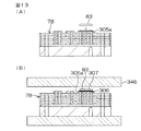
次に、図13(A)に示すように、パワー基板78の導電部305a等にFET83を実装し、図13(B)に示すように、このパワー基板78をリフロー炉346内に送る。その後、パワー基板78をリフロー炉346から取り出す。これにより、半田307がFET83およびめっき層306に固着し、FET83が導電部305aに接合される。
以上説明したように、本実施の形態によれば、基板本体301の外側面301cが被覆部材304で覆われていることにより、この外側面301cから、絶縁層を構成する材料等が粉塵(異物)として飛散することを防止できる。
Next, as shown in FIG. 13A, the FET 83 is mounted on the conductive portion 305a of the power substrate 78, and the power substrate 78 is sent into the reflow furnace 346 as shown in FIG. Thereafter, the power substrate 78 is taken out from the reflow furnace 346. Thereby, the solder 307 is fixed to the FET 83 and the plating layer 306, and the FET 83 is joined to the conductive portion 305a.
As described above, according to the present embodiment, since the outer surface 301c of the substrate body 301 is covered with the covering member 304, the material constituting the insulating layer is dust (foreign matter) from the outer surface 301c. ) Can be prevented from scattering.

これにより、基板本体301の表面301a等に異物が付着してしまうことを防止でき、基板本体301にFET83等の電子部品を接合する際の接合不良を確実に防止できる。
また、絶縁層としての第1、第3、第5および第7の層311,313,315,317は、基材としての合成樹脂よりも熱伝導率が高い熱伝導材としてのセラミック粉末等を含んでいる。これにより、第1、第3、第5および第7の層311,313,315,317の熱伝導性を高くすることができ、基板本体301の放熱性をより高くすることができる。
Thereby, it can prevent that a foreign material adheres to the surface 301a etc. of the board | substrate body 301, and can prevent the joining defect at the time of joining electronic components, such as FET83, to the board | substrate body 301 reliably.
The first, third, fifth, and seventh layers 311, 313, 315, and 317 as insulating layers are made of ceramic powder or the like as a heat conductive material having a higher thermal conductivity than a synthetic resin as a base material. Contains. Thereby, the thermal conductivity of the first, third, fifth, and seventh layers 311, 313, 315, and 317 can be increased, and the heat dissipation of the substrate body 301 can be further increased.

さらに、ワイヤボンディングによる接合のための接合部326を、積層方向Dに関して、ビアホール308を避けて配置している。基板本体301のうちビアホール308が形成されている部分は、ビアホール308のパンチを用いた形成作業に伴って凹凸が生じることとなる。その一方で、ビアホール308が形成されていない部分は、ビアホール308を形成する作業が行われないので、基板本体301の表面301aに凹凸が生じることが無い。   Further, the bonding portion 326 for bonding by wire bonding is arranged in the stacking direction D while avoiding the via hole 308. The portion of the substrate main body 301 where the via hole 308 is formed becomes uneven due to the forming operation using the punch of the via hole 308. On the other hand, in the portion where the via hole 308 is not formed, the work for forming the via hole 308 is not performed, so that the surface 301 a of the substrate body 301 is not uneven.

このように、基板本体301の表面301aのうち凹凸が生じていない平滑な部分に接合部326が設けられるので、接合部326と、この接合部326にボンディングされたボンディングワイヤ310との接合を確実に行うことができ、両者の接合強度を十分に確保することができる。しかも、ボンディングパッドのような別部品を用いて接合部326を形成する必要がないので、コスト安価である。   As described above, since the joint portion 326 is provided in a smooth portion of the surface 301a of the substrate body 301 where there is no unevenness, the joint portion 326 and the bonding wire 310 bonded to the joint portion 326 are reliably joined. Therefore, the bonding strength between the two can be sufficiently ensured. In addition, since it is not necessary to form the joint portion 326 using another component such as a bonding pad, the cost is low.

また、位置決め部材318,319を用いることにより、第1のハウジング23の厚肉部77aに対するパワー基板78の位置決めの精度をより高くすることができる。
さらに、基板本体301から粉塵(異物)が発生することが防止されているので、このような異物が電動モータ18の各軸受75,76等に侵入してこれらの軸受75,76の摩耗が促進されることを防止できる。
Further, by using the positioning members 318 and 319, the accuracy of positioning the power board 78 with respect to the thick portion 77a of the first housing 23 can be further increased.
Further, since dust (foreign matter) is prevented from being generated from the substrate body 301, such foreign matter enters the respective bearings 75, 76 of the electric motor 18 and wear of these bearings 75, 76 is accelerated. Can be prevented.

また、多数のビアホール308を備えていることで十分な放熱性が確保されていることから、放熱のためのスペースが少なくて済み、パワー基板78のさらなる小型化を達成することができる。
以上より、基板本体301に実装される各種電子部品の接合不良が確実に防止されているとともに、電動モータ18の軸受75,76等の摩耗が抑制された電動パワーステアリング装置1を実現することができる。
Moreover, since sufficient heat dissipation is ensured by providing a large number of via holes 308, a space for heat dissipation can be reduced, and further miniaturization of the power board 78 can be achieved.
As described above, it is possible to realize the electric power steering apparatus 1 in which the bonding failure of various electronic components mounted on the board body 301 is reliably prevented and the wear of the bearings 75 and 76 of the electric motor 18 is suppressed. it can.

また、電動モータ18のロータ64の回転位置を検出する回転位置検出装置72を、電動モータ18の回転軸37の軸方向X1に関して、電動モータ18のロータ64と第2のハウジング24との間に配置したので、回転位置検出装置72をECU12に近づけて配置することができる。その結果、回転位置検出装置72およびECU12を、経路長の短い内部配線としてのバスバー端子81によって容易に接続することができる。したがって、経路長の長い外部配線が用いられる従来の場合と比較して、電波ノイズの影響を受け難くなる。また、外部配線のための配線部材を削減することができる。   Further, a rotational position detection device 72 that detects the rotational position of the rotor 64 of the electric motor 18 is arranged between the rotor 64 of the electric motor 18 and the second housing 24 with respect to the axial direction X1 of the rotation shaft 37 of the electric motor 18. Since it has been arranged, the rotational position detecting device 72 can be arranged close to the ECU 12. As a result, the rotational position detection device 72 and the ECU 12 can be easily connected by the bus bar terminal 81 as an internal wiring having a short path length. Therefore, compared to the conventional case where external wiring having a long path length is used, it is less susceptible to radio noise. In addition, wiring members for external wiring can be reduced.

また、収容室100の一部を区画する第2のハウジング24の第2の内壁面102が、電動モータ18の回転軸37の中心軸線C1(またはその延長線C2)とは直交し且つ中心軸線C1(またはその延長線C2)の回りを取り囲む環状平面を含んでいる。すなわち、電動モータ18の回転軸37の軸方向X1に関して、収容室100内へ不必要な出っ張りがない。したがって、収容室100が上記軸方向X1に関して小型であっても、収容室100として十分な内容積を確保することができ、可及的に電動パワーステアリング装置1を小型化することができる。   In addition, the second inner wall surface 102 of the second housing 24 that divides a part of the storage chamber 100 is orthogonal to the central axis C1 (or an extension line C2 thereof) of the rotating shaft 37 of the electric motor 18 and the central axis. It includes an annular plane that surrounds C1 (or its extension C2). That is, there is no unnecessary protrusion in the storage chamber 100 in the axial direction X1 of the rotating shaft 37 of the electric motor 18. Therefore, even if the storage chamber 100 is small with respect to the axial direction X1, a sufficient internal volume as the storage chamber 100 can be ensured, and the electric power steering apparatus 1 can be miniaturized as much as possible.

また、上記第2のハウジング24が、電動モータ18の動力を操舵機構4に伝達する伝達機構としての減速機構19が収容されたギヤハウジング22であるので下記の利点がある。すなわち、ECU12は、通例、本実施の形態のようにパワー基板78に実装されたスイッチング素子(FET83)等の発熱要素を含んでいる。一方、減速機構19は殆ど発熱しない。このような減速機構19を収容したギヤハウジング22を介して、上記の発熱要素からの熱を収容室100の外部へ効果的に放出することができる。   Further, since the second housing 24 is the gear housing 22 in which the speed reduction mechanism 19 as a transmission mechanism for transmitting the power of the electric motor 18 to the steering mechanism 4 is accommodated, there are the following advantages. That is, the ECU 12 typically includes a heating element such as a switching element (FET 83) mounted on the power board 78 as in the present embodiment. On the other hand, the speed reduction mechanism 19 hardly generates heat. The heat from the heat generating element can be effectively released to the outside of the storage chamber 100 through the gear housing 22 in which the speed reduction mechanism 19 is stored.

また、電動モータ18の回転軸37の中心軸線C1に沿う方向に関して、制御基板79および継手38の互いの少なくとも一部が重なるように配置されているので、電動パワーステアリング装置1をより小型にすることができる。
第2の内壁面102のなす環状平面の延長面P1が、操舵力を伝達するための軸(本実施の形態ではステアリングシャフト6に相当)を取り囲む筒状部としての従動ギヤ収容ハウジング28の外周面28aの主要部のなす円筒面P2と図4のように交差するか、または接する状態にある。したがって、電動モータ18の回転軸37の軸方向X1に関して、収容室100を、ステアリングシャフト6側に十分に近づけて配置することになり、回転軸37の軸方向X1に関して、電動パワーステアリング装置1をより小型にすることができる。
Further, since the control board 79 and the joint 38 are arranged so that at least a part of each other overlaps in the direction along the central axis C1 of the rotating shaft 37 of the electric motor 18, the electric power steering device 1 is further reduced in size. be able to.
An outer peripheral surface of the driven gear housing 28 as a cylindrical portion surrounding the shaft (corresponding to the steering shaft 6 in the present embodiment) of the annular flat surface formed by the second inner wall surface 102 and transmitting the steering force. The cylindrical surface P2 formed by the main part of the surface 28a intersects or is in contact with the cylindrical surface P2 as shown in FIG. Accordingly, the storage chamber 100 is disposed sufficiently close to the steering shaft 6 side with respect to the axial direction X1 of the rotating shaft 37 of the electric motor 18, and the electric power steering device 1 is disposed with respect to the axial direction X1 of the rotating shaft 37. It can be made smaller.

なお、操舵力を伝達するための軸としては、上記のステアリングシャフト6に限らず、操舵機構4としてのラックアンドピニオン機構のピニオン軸13であってもよいし、また、ラック軸14であってもよい。前者の場合、ピニオン軸13を取り囲む筒状のピニオンハウジング(図示せず)の外周面の主要部のなす円筒面と、上記延長面P1とが交差または接することになる。また、後者の場合、ラック軸14を取り囲む筒状のラックハウジング(図示せず)の外周面の主要部のなす円筒面と、上記延長面P1とが交差または接することになる。   The shaft for transmitting the steering force is not limited to the steering shaft 6 described above, but may be a pinion shaft 13 of a rack and pinion mechanism as the steering mechanism 4 or a rack shaft 14. Also good. In the former case, the cylindrical surface formed by the main part of the outer peripheral surface of a cylindrical pinion housing (not shown) surrounding the pinion shaft 13 and the extension surface P1 intersect or contact each other. In the latter case, the cylindrical surface formed by the main part of the outer peripheral surface of a cylindrical rack housing (not shown) surrounding the rack shaft 14 and the extension surface P1 intersect or contact each other.

また、制御装置としてのECU12を、電動モータ18の回転軸37の中心軸線C1または上記中心軸線C1の延長線C2の回りに配置したので、収容室100の内部のスペースをECU12の配置に有効に利用することができ、ひいては、回転軸37の軸方向X1に関して、電動パワーステアリング装置1をより小型にすることができる。
また、上記第1のハウジング23は、収容室100とモータ室70とを仕切る仕切り壁77を含み、パワー基板78が仕切り壁77の第1の内壁面101に相対的に近接して設けられている。特に、パワー基板78が、仕切り壁77の厚肉部77aにおける、第1の内壁面101に対して熱伝導可能に接触している。したがって、第1のハウジング23の仕切り壁77の厚肉部77aをヒートシンクとして利用して、FET83等の発熱要素を有するパワー基板78の熱を第1のハウジング23からこれに接触する第2のハウジング24側へ効果的に逃がすことができる。
Further, since the ECU 12 as the control device is arranged around the central axis C1 of the rotating shaft 37 of the electric motor 18 or the extension line C2 of the central axis C1, the space inside the accommodation chamber 100 is effectively used for the arrangement of the ECU 12. Therefore, the electric power steering apparatus 1 can be made smaller with respect to the axial direction X1 of the rotating shaft 37.
The first housing 23 includes a partition wall 77 that partitions the housing chamber 100 and the motor chamber 70, and a power board 78 is provided relatively close to the first inner wall surface 101 of the partition wall 77. Yes. In particular, the power substrate 78 is in contact with the first inner wall surface 101 in the thick portion 77a of the partition wall 77 so as to be capable of conducting heat. Therefore, by using the thick portion 77a of the partition wall 77 of the first housing 23 as a heat sink, the heat of the power board 78 having a heat generating element such as the FET 83 is contacted from the first housing 23 to the second housing. It can escape effectively to 24 side.

収容室100内において、第1のハウジング23の仕切り壁77の薄肉部77bに対向する収容空間S1は、電動モータ18の回転軸37の軸方向X1に関して、十分な高さを有しているので、この収容空間S1には、図5に示すコンデンサ85やリレー86等の背の高い部品を収容することにより、収容室100内の空間の有効利用が図られている。
また、図示していないが、ステアリングホイール2の操舵角を検出する操舵状態検出センサとしての操舵角センサを収容したハウジングと上記の第2のハウジングとが兼用された構成であってもよい。
In the accommodation chamber 100, the accommodation space S <b> 1 that faces the thin portion 77 b of the partition wall 77 of the first housing 23 has a sufficient height with respect to the axial direction X <b> 1 of the rotating shaft 37 of the electric motor 18. In this accommodation space S1, effective use of the space in the accommodation chamber 100 is achieved by accommodating tall components such as the capacitor 85 and the relay 86 shown in FIG.
Further, although not shown, a structure in which a housing that houses a steering angle sensor as a steering state detection sensor that detects a steering angle of the steering wheel 2 and the second housing described above may be used.

本発明は、以上の実施形態の内容に限定されるものではなく、請求項記載の範囲内において種々の変更が可能である。例えば、ピン部材309は、樹脂が埋設された銅部材であってもよい。また、位置決め部材318,319の何れかを廃止してもよい。パワー基板78は、第1のハウジング23の第1の壁101に沿わされていることから、1本の位置決め部材でも、パワー基板78の位置決めを精度良く行うことができる。また、断面多角形形状の位置決め部材を用いれば、1本の位置決め部材でも、パワー基板78が位置決め部材の周りを回動してしまうことを防止できる。   The present invention is not limited to the contents of the above embodiments, and various modifications can be made within the scope of the claims. For example, the pin member 309 may be a copper member in which a resin is embedded. Further, any one of the positioning members 318 and 319 may be eliminated. Since the power board 78 runs along the first wall 101 of the first housing 23, the positioning of the power board 78 can be performed with a single positioning member with high accuracy. Further, if a positioning member having a polygonal cross section is used, it is possible to prevent the power board 78 from rotating around the positioning member even with a single positioning member.

上述の実施形態では、いわゆるコラムアシスト式の電動パワーステアリング装置に本発明が適用された例について説明したが、これに限らず、いわゆるピニオンアシスト式の電動パワーステアリング装置や、いわゆるラックアシスト式の電動パワーステアリング装置に、本発明を適用してもよい。
また、上述の実施形態では、本発明が、電動モータの出力を操舵補助力として出力する電動パワーステアリング装置に適用された例について説明したが、これに限らない。例えば、操舵部材の操舵角に対する転舵輪の転舵角の比を変更可能な伝達比可変機構を備え、伝達比可変機構を駆動するために電動モータの出力を用いる伝達比可変式の車両用操舵装置や、操舵部材と転舵輪との機械的な連結が解除され、転舵輪を電動モータの出力で操向するステア・バイ・ワイヤ式の車両用操舵装置等に、本発明を適用してもよい。
In the above-described embodiment, an example in which the present invention is applied to a so-called column assist type electric power steering apparatus has been described. The present invention may be applied to a power steering device.
In the above-described embodiment, the example in which the present invention is applied to the electric power steering apparatus that outputs the output of the electric motor as the steering assist force has been described, but the present invention is not limited thereto. For example, a transmission ratio variable mechanism that includes a transmission ratio variable mechanism capable of changing a ratio of a steered wheel turning angle to a steering angle of a steering member, and that uses an output of an electric motor to drive the transmission ratio variable mechanism, is used for vehicle steering. Even if the present invention is applied to a device, a steer-by-wire type vehicle steering device in which the mechanical connection between the steering member and the steered wheel is released and the steered wheel is steered by the output of the electric motor, etc. Good.

また、ECU12のパワー基板78および制御基板79の少なくとも一部を樹脂でモールドするようにしてもよい。
また、上述の実施形態では、電動モータ18として、ブラシレスモータを用いる例について説明したが、これに限らず、ブラシレスモータ以外のモータを、電動モータ18として用いてもよい。
Further, at least a part of the power board 78 and the control board 79 of the ECU 12 may be molded with resin.
In the above-described embodiment, an example in which a brushless motor is used as the electric motor 18 has been described. However, the invention is not limited thereto, and a motor other than the brushless motor may be used as the electric motor 18.

本発明の一実施形態に係る車両用操舵装置としての電動パワーステアリング装置の概略構成を示す模式図である。It is a mimetic diagram showing a schematic structure of an electric power steering device as a vehicle steering device concerning one embodiment of the present invention. 操舵補助機構の概略斜視図である。It is a schematic perspective view of a steering assist mechanism. 操舵補助機構を図2とは別角度からみた、操舵補助機構の概略斜視図である。FIG. 3 is a schematic perspective view of the steering assist mechanism when the steering assist mechanism is viewed from an angle different from that of FIG. 2. 電動モータの軸方向に沿って切断された、操舵補助機構の図解的な断面図である。It is an illustration sectional view of a steering auxiliary mechanism cut along the axial direction of an electric motor. 第1のハウジングおよびこれに収容されるECUの部品の分解斜視図である。It is a disassembled perspective view of the 1st housing and the components of ECU accommodated in this. 図4の要部の拡大図である。It is an enlarged view of the principal part of FIG. パワー基板の模式的平面図である。It is a typical top view of a power board. パワー基板が第1のハウジングの厚肉部に固定された状態を示す要部の断面図である。It is sectional drawing of the principal part which shows the state by which the power board was fixed to the thick part of the 1st housing. 図7のIX−IX線に沿う要部の断面図である。It is sectional drawing of the principal part along the IX-IX line of FIG. 基板ユニットの製造について説明するための要部の断面図であり、(A)は、打ち抜き工程を示しており、(B)は、コーティング工程を示しており、(C)は、孔あけ工程を示している。It is sectional drawing of the principal part for demonstrating manufacture of a board | substrate unit, (A) has shown the punching process, (B) has shown the coating process, (C) has carried out the punching process. Show. 基板ユニットの製造について説明するための要部の断面図であり、(A)は、ピン部材の圧入工程を示しており、(B)は、めっき工程を示している。It is sectional drawing of the principal part for demonstrating manufacture of a board | substrate unit, (A) has shown the press injection process of the pin member, (B) has shown the plating process. 基板ユニットの製造について説明するための要部の断面図であり、(A)は、基板本体に金属ベースを固定する工程を示しており、(B)は、酸素プラズマを当てる工程を示しており、(C)は、水素プラズマを当てる工程を示している。It is sectional drawing of the principal part for demonstrating manufacture of a board | substrate unit, (A) has shown the process of fixing a metal base to a board | substrate body, (B) has shown the process of applying oxygen plasma. , (C) shows a step of applying hydrogen plasma. 基板ユニットの製造について説明するための要部の断面図であり、(A)は、電子部品を実装する工程を示しており、(B)は、半田リフロー工程を示している。It is sectional drawing of the principal part for demonstrating manufacture of a board | substrate unit, (A) has shown the process of mounting an electronic component, (B) has shown the solder reflow process.

符号の説明Explanation of symbols

1…電動パワーステアリング装置(車両用操舵装置)、4…操舵機構、18…電動モータ、77a…厚肉部(基板設置部材)、78…パワー基板(積層回路基板、モータ制御装置)、82…モータ駆動回路、83…FET(モータ駆動用素子)、301…基板本体、301a…(基板本体の)表面、301b…(基板本体の)裏面、301c…(基板本体の)外側面、302…金属ベース、304…被覆部材、308…ビアホール、311,313,315,317…絶縁層、312,314,316…導体を含む層、312a,312c,314a,316a,316b,316d…導電部(導体)、318,319…位置決め部材、321a,321b…第1の位置決め孔、326…接合部、D…積層方向。   DESCRIPTION OF SYMBOLS 1 ... Electric power steering apparatus (steering apparatus for vehicles), 4 ... Steering mechanism, 18 ... Electric motor, 77a ... Thick part (board | substrate installation member), 78 ... Power board (laminated circuit board, motor control apparatus), 82 ... Motor drive circuit, 83... FET (motor drive element), 301... Substrate body, 301 a... (Surface of substrate body), 301 b... (Back surface of substrate body), 301 c. Base, 304 ... Cover member, 308 ... Via hole, 311, 313, 315, 317 ... Insulating layer, 312, 314, 316 ... Layer including conductor, 312a, 312c, 314a, 316a, 316b, 316d ... Conductive part (conductor) 318, 319 ... positioning members, 321a, 321b ... first positioning holes, 326 ... joints, D ... stacking direction.

Claims (6)

導体を含む層と絶縁層とを積層してなる基板本体と、
被覆部材とを備え、
上記基板本体は、積層方向に対向する表面および裏面と、側面とを含み、
上記側面は、上記被覆部材によって被覆されていることを特徴とする積層回路基板。
A substrate body formed by laminating a layer including a conductor and an insulating layer;
A covering member,
The substrate body includes a front surface and a back surface facing the stacking direction, and a side surface,
The laminated circuit board, wherein the side surface is covered with the covering member.
請求項1において、上記絶縁層は、基材と、この基材よりも熱伝導率が高い熱伝導材とを含む積層回路基板。   2. The laminated circuit board according to claim 1, wherein the insulating layer includes a base material and a heat conductive material having a higher thermal conductivity than the base material. 請求項1または2において、上記基板本体にはビアホールが設けられ、
上記基板本体の表面は、ワイヤボンディングによる接合のための接合部を含み、
上記接合部は、上記積層方向に関して、上記ビアホールを避けて配置されている積層回路基板。
In Claim 1 or 2, the substrate body is provided with a via hole,
The surface of the substrate body includes a bonding portion for bonding by wire bonding,
The laminated circuit board is arranged such that the joining portion avoids the via hole in the lamination direction.
請求項1〜3の何れかにおいて、上記積層回路基板は、基板本体の裏面に接合される金属ベースと、この金属ベースに形成される位置決め孔とを備え、
上記位置決め孔に、上記金属ベースが設置される基板設置部材に形成された位置決め部材を嵌合可能である積層回路基板。
In any one of Claims 1-3, the said laminated circuit board is equipped with the metal base joined to the back surface of a board | substrate body, and the positioning hole formed in this metal base,
A laminated circuit board capable of fitting a positioning member formed on a board installation member on which the metal base is installed into the positioning hole.
請求項1〜4の何れか1項に記載の積層回路基板と、
上記積層回路基板の基板本体に実装されたモータ駆動用素子を含むモータ駆動回路とを含むモータ制御装置。
The laminated circuit board according to any one of claims 1 to 4,
A motor control device comprising: a motor drive circuit including a motor drive element mounted on the board body of the multilayer circuit board.
請求項5に記載のモータ制御装置と、
上記モータ制御装置によって駆動され、操舵機構に操舵力を付与する電動モータとを備える車両用操舵装置。
A motor control device according to claim 5;
A vehicle steering apparatus comprising: an electric motor that is driven by the motor control apparatus and applies a steering force to a steering mechanism.
JP2008125118A 2008-05-12 2008-05-12 Laminated circuit board, motor controller and steering device for vehicle Pending JP2009277726A (en)

Priority Applications (1)

Application Number Priority Date Filing Date Title
JP2008125118A JP2009277726A (en) 2008-05-12 2008-05-12 Laminated circuit board, motor controller and steering device for vehicle

Applications Claiming Priority (1)

Application Number Priority Date Filing Date Title
JP2008125118A JP2009277726A (en) 2008-05-12 2008-05-12 Laminated circuit board, motor controller and steering device for vehicle

Publications (2)

Publication Number Publication Date
JP2009277726A true JP2009277726A (en) 2009-11-26
JP2009277726A5 JP2009277726A5 (en) 2011-10-27

Family

ID=41442914

Family Applications (1)

Application Number Title Priority Date Filing Date
JP2008125118A Pending JP2009277726A (en) 2008-05-12 2008-05-12 Laminated circuit board, motor controller and steering device for vehicle

Country Status (1)

Country Link
JP (1) JP2009277726A (en)

Cited By (10)

* Cited by examiner, † Cited by third party
Publication number Priority date Publication date Assignee Title
JP2010195219A (en) * 2009-02-25 2010-09-09 Nsk Ltd Electric power steering device
JP2012009609A (en) * 2010-06-24 2012-01-12 Jtekt Corp Multi-layer circuit board
JP2012009608A (en) * 2010-06-24 2012-01-12 Jtekt Corp Element mounting circuit and method for mounting semiconductor element to circuit board
WO2012153402A1 (en) * 2011-05-11 2012-11-15 三菱電機株式会社 Electric power steering device
EP2635096A1 (en) 2012-02-28 2013-09-04 Jtekt Corporation Control unit for electric motor and vehicle steering system including the same
JP2014090030A (en) * 2012-10-29 2014-05-15 Jtekt Corp Control device and vehicle steering gear including the same
EP2779811A1 (en) 2013-03-11 2014-09-17 Jtekt Corporation Drive circuit device
US9686854B2 (en) 2012-09-25 2017-06-20 Denso Corporation Electronic device
JP2018039497A (en) * 2016-07-29 2018-03-15 ジョンソン エレクトリック ソシエテ アノニム Electronic control unit (ecu), control box, and cooling fan module (cfm) having them
JP2018098397A (en) * 2016-12-14 2018-06-21 株式会社デンソー Circuit board

Citations (6)

* Cited by examiner, † Cited by third party
Publication number Priority date Publication date Assignee Title
JPS57170579U (en) * 1981-04-22 1982-10-27
JPH0626297U (en) * 1992-08-28 1994-04-08 株式会社安川電機 Circuit board storage device
JPH06132670A (en) * 1992-10-16 1994-05-13 Nippondenso Co Ltd Metal base multi layer interconnection substrate
JP2000253537A (en) * 1999-02-26 2000-09-14 Sumitomo Wiring Syst Ltd Electric junction box
JP2002120739A (en) * 2000-10-18 2002-04-23 Mitsubishi Electric Corp Electric power steering device
JP2007329371A (en) * 2006-06-09 2007-12-20 Shin Kobe Electric Mach Co Ltd Laminate circuit board

Patent Citations (6)

* Cited by examiner, † Cited by third party
Publication number Priority date Publication date Assignee Title
JPS57170579U (en) * 1981-04-22 1982-10-27
JPH0626297U (en) * 1992-08-28 1994-04-08 株式会社安川電機 Circuit board storage device
JPH06132670A (en) * 1992-10-16 1994-05-13 Nippondenso Co Ltd Metal base multi layer interconnection substrate
JP2000253537A (en) * 1999-02-26 2000-09-14 Sumitomo Wiring Syst Ltd Electric junction box
JP2002120739A (en) * 2000-10-18 2002-04-23 Mitsubishi Electric Corp Electric power steering device
JP2007329371A (en) * 2006-06-09 2007-12-20 Shin Kobe Electric Mach Co Ltd Laminate circuit board

Cited By (20)

* Cited by examiner, † Cited by third party
Publication number Priority date Publication date Assignee Title
JP2010195219A (en) * 2009-02-25 2010-09-09 Nsk Ltd Electric power steering device
JP2012009609A (en) * 2010-06-24 2012-01-12 Jtekt Corp Multi-layer circuit board
JP2012009608A (en) * 2010-06-24 2012-01-12 Jtekt Corp Element mounting circuit and method for mounting semiconductor element to circuit board
WO2012153402A1 (en) * 2011-05-11 2012-11-15 三菱電機株式会社 Electric power steering device
CN103502081B (en) * 2011-05-11 2016-02-10 三菱电机株式会社 Driven steering device
US9099901B2 (en) 2011-05-11 2015-08-04 Mitsubishi Electric Corporation Electric power steering apparatus
JP5619279B2 (en) * 2011-05-11 2014-11-05 三菱電機株式会社 Electric power steering device
CN103502081A (en) * 2011-05-11 2014-01-08 三菱电机株式会社 Electric power steering device
CN103287483A (en) * 2012-02-28 2013-09-11 株式会社捷太格特 Control unit for electric motor and vehicle steering system including the same
CN103287483B (en) * 2012-02-28 2016-12-07 株式会社捷太格特 The controlling device and possess its vehicle steering operation device of electro-motor
JP2013179762A (en) * 2012-02-28 2013-09-09 Jtekt Corp Control device for electric motor and vehicle steering device including the same
US9178402B2 (en) 2012-02-28 2015-11-03 Jtekt Corporation Control unit for electric motor and vehicle steering system including the same
EP2635096A1 (en) 2012-02-28 2013-09-04 Jtekt Corporation Control unit for electric motor and vehicle steering system including the same
US9686854B2 (en) 2012-09-25 2017-06-20 Denso Corporation Electronic device
JP2014090030A (en) * 2012-10-29 2014-05-15 Jtekt Corp Control device and vehicle steering gear including the same
JP2014176225A (en) * 2013-03-11 2014-09-22 Jtekt Corp Drive circuit device
US9373560B2 (en) 2013-03-11 2016-06-21 Jtekt Corporation Drive circuit device
EP2779811A1 (en) 2013-03-11 2014-09-17 Jtekt Corporation Drive circuit device
JP2018039497A (en) * 2016-07-29 2018-03-15 ジョンソン エレクトリック ソシエテ アノニム Electronic control unit (ecu), control box, and cooling fan module (cfm) having them
JP2018098397A (en) * 2016-12-14 2018-06-21 株式会社デンソー Circuit board

Similar Documents

Publication Publication Date Title
JP2009277726A (en) Laminated circuit board, motor controller and steering device for vehicle
JP5316839B2 (en) Motor and vehicle steering apparatus including the same
JP5397658B2 (en) Vehicle steering apparatus and subassembly transfer method
JP5063722B2 (en) Electric drive device and electric power steering device equipped with the same
US10424991B2 (en) Drive device
JP4246212B2 (en) Electric power steering device
JP5634610B2 (en) Electric drive
WO2014188803A1 (en) Power conversion apparatus
WO2009101788A1 (en) Vehicle steering device
JP5397652B2 (en) Vehicle steering system
US20120014070A1 (en) Control device
WO2007007880A1 (en) Electric power steering device
JP5071728B2 (en) Motor control device and vehicle steering apparatus provided with the same
JP2016119794A (en) Drive device
JP2016146702A (en) Electric driving device and electric power steering device
JP6040602B2 (en) Motor unit
JP5397654B2 (en) Vehicle steering system
JP2010273494A (en) Motor drive device
JP5234331B2 (en) Vehicle steering system
JP2014008796A (en) Electric power steering device
US8576573B2 (en) Controller, electric power steering provided with the same, method of manufacturing bus bar, and method of manufacturing controller
WO2019159406A1 (en) Electronic control device and electric drive device
JP5196237B2 (en) Vehicle steering system
JP2009190477A (en) Steering device for vehicle
JP5397659B2 (en) Vehicle steering system

Legal Events

Date Code Title Description
A621 Written request for application examination

Free format text: JAPANESE INTERMEDIATE CODE: A621

Effective date: 20110218

A521 Written amendment

Free format text: JAPANESE INTERMEDIATE CODE: A523

Effective date: 20110901

A521 Written amendment

Free format text: JAPANESE INTERMEDIATE CODE: A523

Effective date: 20110905

A977 Report on retrieval

Free format text: JAPANESE INTERMEDIATE CODE: A971007

Effective date: 20120517

A131 Notification of reasons for refusal

Free format text: JAPANESE INTERMEDIATE CODE: A131

Effective date: 20120607

A521 Written amendment

Free format text: JAPANESE INTERMEDIATE CODE: A523

Effective date: 20120803

A02 Decision of refusal

Free format text: JAPANESE INTERMEDIATE CODE: A02

Effective date: 20130221