JP5397652B2 - Vehicle steering system - Google Patents
Vehicle steering system Download PDFInfo
- Publication number
- JP5397652B2 JP5397652B2 JP2008031109A JP2008031109A JP5397652B2 JP 5397652 B2 JP5397652 B2 JP 5397652B2 JP 2008031109 A JP2008031109 A JP 2008031109A JP 2008031109 A JP2008031109 A JP 2008031109A JP 5397652 B2 JP5397652 B2 JP 5397652B2
- Authority
- JP
- Japan
- Prior art keywords
- housing
- heat
- electric motor
- shaft
- steering
- Prior art date
- Legal status (The legal status is an assumption and is not a legal conclusion. Google has not performed a legal analysis and makes no representation as to the accuracy of the status listed.)
- Expired - Fee Related
Links
Images


Classifications
-
- B—PERFORMING OPERATIONS; TRANSPORTING
- B62—LAND VEHICLES FOR TRAVELLING OTHERWISE THAN ON RAILS
- B62D—MOTOR VEHICLES; TRAILERS
- B62D5/00—Power-assisted or power-driven steering
- B62D5/04—Power-assisted or power-driven steering electrical, e.g. using an electric servo-motor connected to, or forming part of, the steering gear
- B62D5/0403—Power-assisted or power-driven steering electrical, e.g. using an electric servo-motor connected to, or forming part of, the steering gear characterised by constructional features, e.g. common housing for motor and gear box
- B62D5/0406—Power-assisted or power-driven steering electrical, e.g. using an electric servo-motor connected to, or forming part of, the steering gear characterised by constructional features, e.g. common housing for motor and gear box including housing for electronic control unit
-
- B—PERFORMING OPERATIONS; TRANSPORTING
- B62—LAND VEHICLES FOR TRAVELLING OTHERWISE THAN ON RAILS
- B62D—MOTOR VEHICLES; TRAILERS
- B62D5/00—Power-assisted or power-driven steering
- B62D5/04—Power-assisted or power-driven steering electrical, e.g. using an electric servo-motor connected to, or forming part of, the steering gear
- B62D5/0409—Electric motor acting on the steering column
-
- H—ELECTRICITY
- H02—GENERATION; CONVERSION OR DISTRIBUTION OF ELECTRIC POWER
- H02K—DYNAMO-ELECTRIC MACHINES
- H02K11/00—Structural association of dynamo-electric machines with electric components or with devices for shielding, monitoring or protection
- H02K11/30—Structural association with control circuits or drive circuits
- H02K11/33—Drive circuits, e.g. power electronics
-
- H—ELECTRICITY
- H02—GENERATION; CONVERSION OR DISTRIBUTION OF ELECTRIC POWER
- H02K—DYNAMO-ELECTRIC MACHINES
- H02K7/00—Arrangements for handling mechanical energy structurally associated with dynamo-electric machines, e.g. structural association with mechanical driving motors or auxiliary dynamo-electric machines
- H02K7/10—Structural association with clutches, brakes, gears, pulleys or mechanical starters
- H02K7/116—Structural association with clutches, brakes, gears, pulleys or mechanical starters with gears
- H02K7/1163—Structural association with clutches, brakes, gears, pulleys or mechanical starters with gears where at least two gears have non-parallel axes without having orbital motion
- H02K7/1166—Structural association with clutches, brakes, gears, pulleys or mechanical starters with gears where at least two gears have non-parallel axes without having orbital motion comprising worm and worm-wheel
-
- H—ELECTRICITY
- H02—GENERATION; CONVERSION OR DISTRIBUTION OF ELECTRIC POWER
- H02K—DYNAMO-ELECTRIC MACHINES
- H02K9/00—Arrangements for cooling or ventilating
- H02K9/22—Arrangements for cooling or ventilating by solid heat conducting material embedded in, or arranged in contact with, the stator or rotor, e.g. heat bridges
- H02K9/223—Heat bridges
-
- H—ELECTRICITY
- H02—GENERATION; CONVERSION OR DISTRIBUTION OF ELECTRIC POWER
- H02K—DYNAMO-ELECTRIC MACHINES
- H02K9/00—Arrangements for cooling or ventilating
- H02K9/22—Arrangements for cooling or ventilating by solid heat conducting material embedded in, or arranged in contact with, the stator or rotor, e.g. heat bridges
- H02K9/227—Heat sinks
Description
本発明は、車両用操舵装置に関するものである。 The present invention relates to a vehicle steering apparatus.
車両用操舵装置としての電動パワーステアリング装置は、電動モータによって運転者の操舵を補助するようになっている。すなわち、各種のセンサ等によって操舵部材の操舵状態等が検出され、この検出値に基づいて制御装置が電動モータを制御することで、転舵機構に操舵補助力が付与される。
電動モータの軸方向に関して、電動モータと減速機構との間に、制御装置を配置することが提案されている(例えば特許文献1を参照)。
An electric power steering device as a vehicle steering device assists a driver's steering with an electric motor. That is, the steering state of the steering member is detected by various sensors and the like, and the control device controls the electric motor based on the detected value, so that a steering assist force is applied to the steering mechanism.
With respect to the axial direction of the electric motor, it has been proposed to arrange a control device between the electric motor and the speed reduction mechanism (see, for example, Patent Document 1).
特許文献1の電動パワーステアリング装置では、モータハウジングとギヤハウジングとの間に共通のケースを介装している。上記ケースとモータハウジングとの間に、モータ室が区画されているとともに、ケースとギヤハウジングとの間に、コントローラ室が区画されている。
特許文献1の電動パワーステアリング装置では、コントローラ室内において、モータ側の内壁面に沿わせて、制御装置を取り付けている。通例、電動モータは熱を持つ傾向にあり、その電動モータに近づけて制御装置を配置することになる。したがって、制御装置の発熱要素の熱を外部に逃がし難いという問題がある。
本発明は、かかる背景のもとになされたものであり、小型で放熱性に優れた車両用操舵装置を提供することを目的とする。
In the electric power steering device of Patent Document 1, a control device is attached along the inner wall surface on the motor side in the controller room. Usually, the electric motor tends to have heat, and the control device is arranged close to the electric motor. Therefore, there is a problem that it is difficult to release the heat of the heating element of the control device to the outside.
The present invention has been made based on such a background, and an object of the present invention is to provide a vehicle steering apparatus that is small in size and excellent in heat dissipation.
上記目的を達成するため、本発明は、電動モータ(18)の駆動を制御する制御装置(12)と、この制御装置を収容する収容室(100)を区画する制御ハウジング(H)と、この制御ハウジングに対して電動モータとは反対側に隣接する隣接ハウジング(22)と、制御ハウジングおよび隣接ハウジングの間に配置された熱伝導部材(120;130)とを備え、この熱伝導部材の一端(121)が、制御装置の発熱要素(83)に熱伝導可能に近接し、他端(122)が隣接ハウジングに熱伝導可能に接続されており、上記制御ハウジングは、収容室の一部を区画し且つ電動モータの回転軸(37)の軸方向(X1)に対向する第1および第2の内壁面(101,102)を含み、第1の内壁面は電動モータに相対的に近くに配置されるとともに、第2の内壁面は電動モータから相対的に遠くに配置され、上記制御装置の発熱要素は、第2の内壁面に熱伝導可能に取り付けられたパワー基板(78)に実装されており、熱伝導部材の上記一端は、第2の内壁面に連続するヒートシンク(123)に熱伝導可能に近接していることを特徴とするものである。 In order to achieve the above object, the present invention provides a control device (12) for controlling the driving of the electric motor (18), a control housing (H) for defining a storage chamber (100) for storing the control device, An adjacent housing (22) adjacent to the control housing opposite to the electric motor, and a heat conducting member (120; 130) disposed between the control housing and the adjacent housing, and one end of the heat conducting member (121), thermally conductively proximity to the heating element (83) of the control device, the other end (122) are connected in a thermally conductive to adjacent housing, the control housing, a portion of the accommodating chamber It includes first and second inner wall surfaces (101, 102) that partition and oppose the axial direction (X1) of the rotating shaft (37) of the electric motor, and the first inner wall surface is relatively close to the electric motor. Placed In addition, the second inner wall surface is disposed relatively far from the electric motor, and the heat generating element of the control device is mounted on a power board (78) attached to the second inner wall surface so as to conduct heat. The one end of the heat conducting member is close to the heat sink (123) continuous with the second inner wall surface so as to be able to conduct heat .
本発明によれば、制御装置の発熱要素からの熱を、発熱する電動モータのハウジングに対してではなく、電動モータとは反対側に隣接するハウジングに対して、熱伝導部材を介して放熱するようにしているので、放熱性を格段に向上することができる。したがって、例えばヒートシンクを小型にすることができ、ひいては小型で放熱性の良い車両用操舵装置を実現することができる。 According to the present invention, heat from the heat generating element of the control device is radiated through the heat conducting member to the housing adjacent to the opposite side of the electric motor, not to the housing of the electric motor that generates heat. Since it is doing, heat dissipation can be improved significantly. Therefore, for example, the heat sink can be reduced in size, and as a result, a vehicle steering apparatus that is small and has good heat dissipation can be realized.
ここで、熱伝導部材としては、アルミニウム、銅などの高熱伝導率を有する部材が用いられる。熱伝導部材としてアルミニウムを用いる場合には、熱伝導部材および隣接ハウジングを単一の材料で一体に形成することも可能である。また、熱伝導部材として、ヒートパイプを用いたり、ヒートパイプを用いた熱伝導構造材(例えばヒートパイプを折って重ねたヒートレーン)を用いることも可能である。 Here, a member having high thermal conductivity such as aluminum or copper is used as the heat conducting member. When aluminum is used as the heat conducting member, the heat conducting member and the adjacent housing can be integrally formed of a single material. Moreover, it is also possible to use a heat pipe as a heat conductive member, or a heat conductive structure material using a heat pipe (for example, a heat lane in which heat pipes are folded and stacked).
また、上記制御ハウジングは、収容室の一部を区画し且つ電動モータの回転軸(37)の軸方向(X1)に対向する第1および第2の内壁面(101,102)を含み、第1の内壁面は電動モータに相対的に近くに配置されるとともに、第2の内壁面は電動モータから相対的に遠くに配置され、上記制御装置の発熱要素は、第2の内壁面に熱伝導可能に取り付けられたパワー基板(78)に実装されており、熱伝導部材の上記一端は、第2の内壁面に連続するヒートシンク(123)に熱伝導可能に近接しているので、下記の利点がある。 The control housing includes first and second inner wall surfaces (101, 102) that define a part of the storage chamber and face the axial direction (X1) of the rotating shaft (37) of the electric motor. The inner wall surface of 1 is disposed relatively close to the electric motor, the second inner wall surface is disposed relatively far from the electric motor, and the heat generating element of the control device heats the second inner wall surface. It is mounted on a power board (78) attached in a conductive manner, and the one end of the heat conducting member is close to the heat sink (123) continuous with the second inner wall surface so that the heat conduction is possible . There are advantages.
すなわち、例えばスイッチング素子等の発熱要素を実装したパワー基板を、隣接ハウジングに近い側の第2の内壁面に熱伝導可能に取り付けている。発熱要素の熱を、パワー基板、第2の内壁面に連続するヒートシンクおよび熱伝導部材を介して、隣接ハウジングに効率的に逃がすことができ、放熱性を向上することができる。したがって、可及的にヒートシンクの小型化を図ることができ、ひいては車両用操舵装置を小型にすることができる。 That is , for example, a power board on which a heating element such as a switching element is mounted is attached to the second inner wall surface on the side close to the adjacent housing so as to be able to conduct heat. The heat of the heat generating element can be efficiently released to the adjacent housing via the power board, the heat sink and the heat conducting member continuous with the second inner wall surface, and the heat dissipation can be improved. Therefore, the heat sink can be miniaturized as much as possible, and the vehicle steering apparatus can be miniaturized.
また、上記隣接ハウジングは、電動モータの動力を転舵機構(4)に伝達する伝達機構(19)が収容されたハウジング(22)を含む場合がある(請求項2)。制御装置は、通例、パワー基板に実装されたスイッチング素子等の発熱要素を含んでいる。一方、伝達機構は殆ど発熱しない。このような伝達機構を収容したハウジングを介して、上記の発熱要素からの熱を収容室の外部へ効果的に放出することができる。 The adjacent housing may include a housing (22) in which a transmission mechanism (19) for transmitting the power of the electric motor to the steering mechanism (4) is accommodated (claim 2 ). The control device typically includes a heating element such as a switching element mounted on the power board. On the other hand, the transmission mechanism hardly generates heat. Heat from the heat generating element can be effectively released to the outside of the storage chamber via the housing that stores such a transmission mechanism.
また、上記伝達機構は、駆動側部材(20)および駆動側部材によって駆動される従動側部材(21)を含み、上記隣接ハウジングは、上記従動側部材が収容された筒状のハウジング(28;280)を含み、上記熱伝導部材は、上記従動側部材が収容された上記ハウジングの端面または外周面(28a)に沿って延びている場合がある(請求項3)。通例、駆動側部材と比較して大型となる従動側部材を収容するハウジングであれば、十分な放熱面積を確保することができるので、放熱性を格段に向上することができる。 The transmission mechanism includes a driving side member (20) and a driven side member (21) driven by the driving side member, and the adjacent housing includes a cylindrical housing (28; containing the driven side member); 280), and the heat conducting member may extend along an end surface or an outer peripheral surface (28a) of the housing in which the driven member is accommodated (Claim 3 ). In general, a housing that accommodates a driven member that is larger than the driving member can secure a sufficient heat radiation area, so that heat dissipation can be significantly improved.
また、上記隣接ハウジングは、操舵状態を検出するための操舵状態検出センサ(11)が収容されたハウジング(35)を含む場合がある(請求項4)。この場合、操舵状態検出センサが収容されたハウジングを介して、スイッチング素子等の発熱要素からの熱を収容室外へ効果的に放出することができる。
また、上記制御装置は、電動モータの回転軸の中心軸線または上記中心軸線の延長線の回りに配置されている場合がある(請求項5)。この場合、収容室の内部のスペースを制御装置の配置に有効に利用することができ、ひいては、電動モータの回転軸の軸方向に関して、車両用操舵装置をより小型にすることができる。
Further, the adjacent housing may include a housing (35) in which a steering state detection sensor (11) for detecting a steering state is accommodated (claim 4 ). In this case, heat from a heat generating element such as a switching element can be effectively released to the outside of the storage chamber via the housing in which the steering state detection sensor is stored.
Moreover, the said control apparatus may be arrange | positioned around the center axis line of the rotating shaft of an electric motor, or the extension line of the said center axis line (Claim 5 ). In this case, the space inside the storage chamber can be effectively used for the arrangement of the control device, and consequently the vehicle steering device can be made smaller with respect to the axial direction of the rotating shaft of the electric motor.
また、上記熱伝導部材は、制御ハウジングから隣接ハウジングへ向けて所定長さLで延び均一な断面を有する部材を含み、熱伝導部材の断面積をA、熱伝導率をρとし、発熱要素の平均損失をBとしたときに、下記式が成立するようにしてある場合がある(請求項6)。
(A2 /L)<(1/ρ)×B
この場合、熱伝導部材の断面積Aと長さLを、十分な伝熱、放熱を発揮できる最適な設定値に設計することが可能である。
The heat conducting member includes a member having a uniform cross section extending from the control housing toward the adjacent housing with a predetermined length L, the cross sectional area of the heat conducting member is A, the thermal conductivity is ρ, When the average loss is B, the following equation may be satisfied (claim 6 ).
(A 2 / L) <(1 / ρ) × B
In this case, the cross-sectional area A and the length L of the heat conducting member can be designed to optimum setting values that can exhibit sufficient heat transfer and heat dissipation.
なお、上記において、括弧内の英数字は、後述の実施形態における対応構成要素の参照符号を表すものであるが、これらの参照符号により特許請求の範囲を限定する趣旨ではない。 In the above description, the alphanumeric characters in parentheses represent reference numerals of corresponding components in the embodiments described later, but the scope of the claims is not limited by these reference numerals.
以下には、図面を参照して、本発明の実施形態について具体的に説明する。
図1は、本発明の一実施形態に係る車両用操舵装置としての電動パワーステアリング装置1の概略構成を示す模式図である。
図1を参照して、電動パワーステアリング装置1は、操舵部材としてのステアリングホイール2と、ステアリングホイール2の回転に連動して転舵輪3を転舵する転舵機構4と、運転者の操舵を補助するための操舵補助機構5とを備えている。ステアリングホイール2と転舵機構4とは、ステアリングシャフト6および中間軸7を介して機械的に連結されている。
Hereinafter, embodiments of the present invention will be specifically described with reference to the drawings.
FIG. 1 is a schematic diagram showing a schematic configuration of an electric power steering apparatus 1 as a vehicle steering apparatus according to an embodiment of the present invention.
Referring to FIG. 1, an electric power steering apparatus 1 includes a
本実施の形態では、操舵補助機構5がステアリングシャフト3にアシスト力(操舵補助力)を与える例に則して説明するが、本発明を、操舵補助機構5が後述するピニオン軸にアシスト力を与える構造や、操舵補助機構5が後述するラック軸にアシスト力を与える構造に適用することが可能である。
ステアリングシャフト6は、直線状に延びている。また、ステアリングシャフト6は、ステアリングホイール2に連結された入力軸8と、中間軸7に連結された出力軸9とを含む。入力軸8と出力軸9とは、トーションバー10を介して同一軸線上で相対回転可能に連結されている。すなわち、ステアリングホイール2に一定値以上の操舵トルクが入力されると、入力軸8および出力軸9は、互いに相対回転しつつ同一方向に回転するようになっている。
In the present embodiment, the
The
ステアリングシャフト6の周囲に配置されたトルクセンサ11は、入力軸8および出力軸9の相対回転変位量に基づいて、ステアリングホイール2に入力された操舵トルクを検出する。トルクセンサ11のトルク検出結果は、制御装置としてのECU12(Electronic Control Unit :電子制御ユニット)に入力される。また、車速センサ90からの車速検出結果がECU12に入力される。中間軸7は、ステアリングシャフト6と転舵機構4とを連結している。
A
転舵機構4は、ピニオン軸13と、転舵軸としてのラック軸14とを含むラックアンドピニオン機構からなる。ラック軸14の各端部には、タイロッド15およびナックルアーム(図示せず)を介して転舵輪3が連結されている。
ピニオン軸13は、中間軸7に連結されている。ピニオン軸13は、ステアリングホイール2の操舵に連動して回転するようになっている。ピニオン軸13の先端(図1では下端)には、ピニオン16が連結されている。
The steered mechanism 4 includes a rack and pinion mechanism including a
The
ラック軸14は、自動車の左右方向に沿って直線状に延びている。ラック軸14の軸方向の途中部には、上記ピニオン16に噛み合うラック17が形成されている。このピニオン16およびラック17によって、ピニオン軸13の回転がラック軸14の軸方向移動に変換される。ラック軸14を軸方向に移動させることで、転舵輪3を転舵することができる。
The
ステアリングホイール2が操舵(回転)されると、この回転が、ステアリングシャフト6および中間軸7を介して、ピニオン軸13に伝達される。そして、ピニオン軸13の回転は、ピニオン16およびラック17によって、ラック軸14の軸方向移動に変換される。これにより、転舵輪3が転舵される。
操舵補助機構5は、操舵補助用の電動モータ18と、電動モータ18の出力トルクを転舵機構4に伝達するための伝達機構としての減速機構19とを含む。減速機構19としては、例えばウォームギヤ機構などの食い違い軸歯車機構や、平行軸歯車機構などを用いることができる。本実施形態では、減速機構19として、ウォームギヤ機構が用いられている。すなわち、減速機構19は、駆動ギヤ(伝達機構の駆動側部材)としてのウォーム軸20と、このウォーム軸20と噛み合う従動ギヤ(伝達機構の従動側部材)としてのウォームホイール21とを含む。減速機構19は、伝達ハウジングとしてのギヤハウジング22内に収容されている。
When the
The
ウォーム軸20は、図示しない継手を介して電動モータ18の回転軸(図示せず)に連結されている。ウォーム軸20は、電動モータ18によって回転駆動される。また、ウォームホイール21は、ステアリングシャフト6とは同行回転可能に連結されている。ウォームホイール21は、ウォーム軸20によって回転駆動される。
電動モータ18がウォーム軸20を回転駆動すると、ウォーム軸20によってウォームホイール21が回転駆動され、ウォームホイール21およびステアリングシャフト6が同行回転する。そして、ステアリングシャフト6の回転は、中間軸7を介してピニオン軸13に伝達される。ピニオン軸13の回転は、ラック軸14の軸方向移動に変換される。これにより、転舵輪3が転舵される。すなわち、電動モータ18によってウォーム軸20を回転駆動することで、転舵輪3が転舵されるようになっている。
The
When the
電動モータ18は、ECU12によって制御される。ECU12は、トルクセンサ11からのトルク検出結果、車速センサ90からの車速検出結果等に基づいて電動モータ18を制御する。具体的には、ECU12では、トルクと目標アシスト量との関係を車速毎に記憶したマップを用いて目標アシスト量を決定し、電動モータ18の発生するアシスト力を目標アシスト量に近づけるように制御する。
The
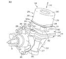
図2および図3は、それぞれ操舵補助機構5の概略斜視図であり、互いに別角度から操舵補助機構5を見た図である。本実施の形態の主に特徴とするところは、上記の制御装置としてのECU12を収容するための制御ハウジングHを、図2および図3に示すように、互いに接触する(例えば互いの端面を突き合わせた状態、或いは互いの端部を嵌合させた状態である)第1のハウジング23および第2のハウジング24によって構成した点にある。
2 and 3 are schematic perspective views of the steering assist
すなわち、ECU12を収容するための制御ハウジングHを構成する第1のハウジング23および第2のハウジング24は互いに接触しており(直接に係合しており)、両ハウジング23,24の間に、別のハウジングが介在していない。これにより、格段の小型化が図られている。
第1のハウジング23および第2のハウジング24は、一端が開放した概ね四角箱形に形成されている。第1および第2のハウジング23,24の互いの端部は、突き合わされ固定ねじ91により互いに締結されている。
That is, the
The
一方、電動モータのモータハウジング25は、筒状のモータハウジング本体26と、上記の第1のハウジング23とにより構成されている。具体的には、ECU12を収容するための制御ハウジングHの一部である第1のハウジング23が、電動モータ12のモータハウジング25の少なくとも一部とは単一の材料で一体に形成されている。換言すると、モータハウジング25の少なくとも一部と、ECU12を収容するための制御ハウジングHの一部とが兼用されている。
On the other hand, the
また、ギヤハウジング22は、ウォーム軸20が収容された筒状の駆動ギヤ収容ハウジング27と、ウォームホイール21が収容された筒状の従動ギヤ収容ハウジング28と、上記の第2のハウジング24とにより構成されている。具体的には、ECU12を収容するための制御ハウジングHの一部である第2のハウジング24が、ギヤハウジング22の駆動ギヤ収容ハウジング27および従動ギヤ収容ハウジング28とは単一の材料で一体に形成されている。換言すると、ギヤハウジング22の一部と、ECU12を収容するための制御ハウジングHの一部とが兼用されている。
The
第1のハウジング23の側壁としての外周壁92の外周92aには、筒状突起93が突出形成されており、その筒状突起93内には、第1のハウジング23の外部に臨む電気コネクタ94が配置されている。図示していないが、電気コネクタ94には、バッテリーからECU12に電源供給するための端子や、外部からの信号の入、出力用の端子が設けられている。
A
電動パワーステアリング装置の要部の断面図である図4を参照して、減速機構19(伝達機構)の従動側部材としてのウォームホイール21、および電気コネクタ94は、減速機構19(伝達機構)の駆動側部材としてのウォーム軸20の中心軸線C3を含み且つウォームホイール21の中心軸線21aとは平行な平面Q1に対して、同側に配置されている。
Referring to FIG. 4 which is a cross-sectional view of the main part of the electric power steering apparatus, the
この場合、電動モータ18の回転軸37の軸方向X1に沿って見たときに、突出部となる電気コネクタ94および従動ギヤ収容ハウジング28が同側に突出することになる。その結果、実質的な小型化および省スペース化を図ることができ、車両への搭載性が向上する。
また、図3を参照して、電動モータ18の後述する回転軸37の軸方向X1に沿って見たときに、電気コネクタ94および従動ギヤ収容ハウジング28の互いの少なくとも一部が互いに重なり合うレイアウトとされている。これにより、実質的な小型化および省スペース化を図ることができ、車両への搭載性が向上する。
In this case, when viewed along the axial direction X1 of the
Further, with reference to FIG. 3, when viewed along an axial direction X1 of a rotating shaft 37 (to be described later) of the
また、回転軸37の軸方向X1に沿って見たときに、電気コネクタ94およびセンサハウジング35の互いの少なくとも一部が互いに重なり合うレイアウトとされている。これにより、実質的な小型化および省スペース化を図ることができ、車両への搭載性が向上する。
モータハウジング25の第1のハウジング23は、例えばアルミニウム合金(例えば鋳造品、冷間鍛造品)により形成され、操舵補助機構5の軽量化が図られている。また、駆動ギヤ収容ハウジング27、従動ギヤ収容ハウジング28および第2のハウジング24で構成されるギヤハウジング22は、例えばアルミニウム合金(例えば鋳造品、冷間鍛造品)により形成され、操舵補助機構5の軽量化が図られている。また、モータハウジング25のモータハウジング本体26には、例えば非磁性の板金が用いられている。
Further, when viewed along the axial direction X1 of the
The
モータハウジング本体26は、円筒状の周壁29と、周壁29の一端を閉塞する底壁30と、周壁29の他端からその径方向外方に張り出した環状のフランジ31とを含む。
環状のフランジ31の周方向の一部から径方向外方に張り出したブラケット32が設けられている。そのブラケット32のねじ挿通孔33に挿通された固定ねじ34が、第1のハウジング23のねじ孔にねじ込まれることにより、モータハウジング本体26と第1のハウジング23とが一体に固定されている。上記のねじ挿通孔33は、モータハウジング本体26の周方向に延びる長孔に形成されているので、第1のハウジング23に対して、モータハウジング本体26の周方向位置を調整可能となっている。
The
A
また、ECU12を収容するための制御ハウジングHを構成する第1のハウジング23および第2のハウジング24は、固定ねじ91を用いて互いに固定されている。
ギヤハウジング22の従動ギヤ収容ハウジング28には、トルクセンサ11が収容された筒状のセンサハウジング35が連結されており、従動ギヤ収容ハウジング28およびセンサハウジング35は、固定ねじ36を用いて互いに固定されている。ステアリングシャフト6が、筒状の従動ギヤ収容ハウジング28およびセンサハウジング35内に挿通されている。
Further, the
A
図4を参照して、電動モータ18のモータハウジング25である第1のハウジング23とこの第1のハウジング23に接触する第2のハウジング24とによって、制御装置としてのECU12を収容する収容室100が形成されている。第1のハウジング23および第2のハウジング24の互いの端面が突き合わされており、両端面間が環状のシール部材95によって封止されている。
Referring to FIG. 4, a
第1のハウジング23は、収容室100の一部を区画する第1の内壁面101を含み、第2のハウジング24は収容室100の一部を区画する第2の内壁面102を含み、これら第1の内壁面101および第2の内壁面102は、電動モータ18の回転軸37の軸方向X1に対向している。
また、第2のハウジング24の第2の内壁面102は、環状平面を含んでおり、その環状平面は、電動モータ18の回転軸37の中心軸線C1または上記中心軸線C1の延長線C2(通例、ウォーム軸20の中心軸線C3に一致)とは直交し且つ上記中心軸線C1または上記延長線C2の回りを取り囲んでいる。また、第2の内壁面102には、環状平面よりも収容室100側へ突出する平坦な座部103が形成されており、その座部103の底が厚肉のヒートシンク123となっている。第2の内壁面102の座部103によって、パワー基板78が熱伝導可能に受けられている。パワー基板78には、電動モータ18を駆動するパワー回路が実装されており、そのパワー回路には、発熱要素としてのFET等のスイッチング素子が含まれている。
The
The second
第2の内壁面102の座部103の延長面P1が、制御ハウジングHに隣接する隣接ハウジングとしての筒状の従動ギヤ収容ハウジング28の外周面28aの主要部のなす円筒面P2と図4のように接するか、または交差する状態にある。
また、制御装置としてのECU12は、回転軸37の中心軸線C1または延長線C2の回りに配置されている。
The extension surface P1 of the
Further, the
電動モータ18の回転軸37およびウォーム軸20が同軸上に並べて配置されており、回転軸37およびウォーム軸20は、互いの間に介在する継手38を介して動力伝達可能に連結されている。継手38は、電動モータ18の回転軸37と同行回転する環状の入力部材39と、ウォーム軸20と同行回転する環状の出力部材40と、入力部材39および出力部材40の間に介在し入力部材39および出力部材40を動力伝達可能に連結する環状の弾性部材41とを有している。
The rotating
ウォーム軸20は、ギヤハウジング22の駆動ギヤ収容ハウジング27の駆動ギヤ収容孔42に収容されている。ウォーム軸20は第1の端部20aおよび第2の端部20bを有しており、ウォーム軸20の軸方向の中間部にウォーム20cが形成されている。
ウォーム軸20の第1の端部20aは、駆動ギヤ収容孔42の一端(電動モータ18側の端部)の内周の軸受保持部44に保持された第1の軸受45によって、回転可能に支持されている。ウォーム軸20の第2の端部20bは、駆動ギヤ収容孔42の他端の内周の軸受保持部46に保持された第2の軸受47によって、回転可能に支持されている。
The
The
第1の軸受45は、内輪48と、外輪49と、内輪48および外輪49の間に介在する複数の転動体50とを有する転がり軸受からなる。内輪48は、ウォーム軸20の第1の端部20aに同行回転可能に保持されている。内輪48の一方の端面は、ウォーム軸20の外周に設けられた位置決め段部に当接している。ウォーム軸20の第1の端部20aには、小径の突軸51が延設されており、その突軸51には、継手38の出力部材40が同行回転可能に且つ軸方向移動不能に嵌合されている。出力部材40は内輪48の他方の端面に当接しており、ウォーム軸20の上記位置決め段部と出力部材40の間に、内輪48が挟持されている。これにより、ウォーム軸20に対する内輪45の軸方向移動が規制されている。
The
外輪49の一方の端面が、駆動ギヤ収容孔42の軸受保持部44の一側に隣接する段部に、所定の隙間を隔てて対向している。また、駆動ギヤ収容孔42の軸受保持部44の他側に隣接するねじ部に、環状の固定部材52がねじ込まれており、固定部材52が外輪49の他方の端面を押圧している。これにより、外輪49の軸方向移動が規制されている。 固定部材52は、外周にねじが形成された筒状の本体52aと、本体52aの一端から径方向内方に延びる内方フランジ52bと、本体52aの他端から径方向外方に延びる外方フランジ52cとを有している。内方フランジ52bが、外輪49の他方の端面を押圧している。また、外方フランジ52cは、ECU12の収容室を区画する第2のハウジング24の第2の内壁面102に押圧されており、これにより、固定部材52の緩み止めが達成されている。
One end surface of the
固定部材52の筒状の本体52a内には、継手38の一部が収容されている。これにより、回転軸37の軸方向X1に関しての、電動パワーステアリング装置1の小型化が達成されている。
第2の軸受47は、内輪53と、外輪54と、内輪53および外輪54の間に介在する複数の転動体55とを有する転がり軸受からなる。内輪53は、ウォーム軸20の第2の端部20bに同行回転可能に保持されている。内輪53の一方の端面は、ウォーム軸20の外周に設けられた位置決め段部に当接している。これにより、ウォーム軸20に対する内輪53の軸方向移動(第1の軸受45側への移動)が規制されている。
A part of the joint 38 is accommodated in the cylindrical
The
駆動ギヤ収容孔42の軸受保持部46に隣接する、駆動ギヤ収容孔42の入口部に、ねじ部56が形成されており、そのねじ部56に、第1および第2の軸受45,47に一括して予圧を付与するための予圧付与部材57がねじ込まれている。予圧付与部材57は、円板状の本体58を有しており、本体58の外周には、上記ねじ部56に螺合するねじ部59が形成されている。また、本体58の一方の端面に、第2の軸受47の外輪54の一方の端面を押圧する環状凸部60が形成されている。
A
本体58の他方の端面には、当該予圧付与部材57を回動操作するための工具を係合する、例えば断面多角形形状の工具係合孔61が形成されている。また、本体58のねじ部59に螺合されたロックナット62によって、予圧付与部材57が止定されるようになっている。
ウォーム軸20の第1および第2の端部20a,20bを支持する第1および第2の軸受45,47は、何れも公知のシール軸受により構成されている。具体的には、転動体の軸方向X1の両側において、内輪と外輪の間を密封するシール部材62を備えており、そのシール部材62は、内輪または外輪の何れか一方に固定される。また、シール部材62は他方に摺接するリップを有している。
A
The first and
ウォーム軸20の両端を支持する第1および第2の軸受45,47がシール軸受により構成されているので、ギヤハウジング22内のグリース等の潤滑剤が、ECU12を収容する収容室100側へ漏れ出ることがない。ただし、収容室100内の密封性を高めるために、例えば、固定部材52の本体52aの外周のねじ部とこれに螺合するねじ部との間に、液体パッキンを介在させてもよい。
Since the first and
本実施形態では、電動モータ18としてブラシレスモータが用いられている。電動モータ18は、上記モータハウジング25と、このモータハウジング25内に収容されたロータ64およびステータ65を含む。
ロータ64は、回転軸37の外周に同行回転可能に取り付けられた環状のロータコア66と、ロータコア66の外周に同行回転可能に取り付けられた例えば環状の永久磁石からなるロータマグネット67とを有している。ロータマグネット67には、複数の磁極が周方向に並べて配置されている。これらの磁極は、ロータ64の周方向に関して、N極およびS極が交互に入れ替わるようにされている。
In the present embodiment, a brushless motor is used as the
The
ステータ65は、モータハウジング25のモータハウジング本体26の内周に固定されている。ステータ65は、モータハウジング本体26の内周に固定されたステータコア68と、複数のコイル69とを含む。ステータコア68は、環状のヨークと、このヨークの内周から径方向内方へ突出する複数のティースとを含む。各コイル69は対応するティースに巻回されている。
The
また、モータハウジング25のモータハウジング本体26と第1のハウジング23とにより区画されるモータ室70内には、環状またはC形形状をなすバスバー71が収容されている。各ティースに巻回されたコイル69は、バスバー71と接続されている。バスバー71は、各コイル69と電流印加線との接続部に用いられる導電接続材であり、バスバー71は、各コイル69に、図示しない電力供給源からの電力を配電するための配電部材として機能する。
A
また、モータハウジング25のモータハウジング本体26と第1のハウジング23とにより区画されるモータ室70内には、ロータ64の回転位置を検出するための回転位置検出装置72が収容されている。回転位置検出装置72は、第1のハウジング23に固定されたステータ73と、回転軸37とは同行回転可能に取り付けられたロータ74とを有している。回転位置検出装置72としては、例えばレゾルバを用いることができる。また、ホール素子を用いることもできる。
A rotation
回転位置検出装置72は、電動モータ18のロータ64のロータコア66と、第2のハウジング24との間に配置されていればよい。したがって、本実施の形態のように、モータ室70内に配置されていてもよいし、ECU12の収容室100を区画する第1のハウジング23の中央に設けられた後述する筒状部89内に配置されていてもよい。
また、図4を参照して、回転軸37は、モータハウジング25の一部とECU12を収容するハウジングの一部とを兼用する第1のハウジング23によって保持された第3の軸受75および第4の軸受76によって、回転可能に支持されている。第3および第4の軸受75,76は、第1および第2の軸受45,47と同じ構成のシール軸受により構成されている。
The rotational
Referring to FIG. 4, the
ECU12の収容室100を区画する制御ハウジングHの一部である第1のハウジング23は、収容室100とモータ室70とを仕切る仕切り壁77を底壁として含んでいる。この仕切り壁77に、上記第1の内壁面101が設けられている。仕切り壁77の外周の近傍からモータハウジング本体26側に向かって筒状突起104が延びており、その筒状突起104の外周に、モータハウジング本体26の一端が嵌合されている。
The
また、仕切り壁77は、上記の第3の軸受75の外輪を保持するための保持孔105を有している。仕切り壁77からモータハウジング本体26側に向けて延びる筒状突起106が形成されている。筒状突起106は上記保持孔105とは同軸的に形成されている。筒状突起106は、モータハウジング本体26に係合する上記の筒状突起104よりも小径に形成されている。この筒状突起106の内周には、回転位置検出装置72のステータ73が固定されている。
The
また、仕切り壁77から第2のハウジング24側に向けて延びる筒状部89が形成されている。筒状部89は上記の保持孔105とは同軸的に形成されている。筒状部89内の内周には、上記の第4の軸受76の外輪が保持されている。筒状部89の一端には、径方向内方に延びる環状フランジ107が延設されており、第4の軸受76の外輪の一端が環状フランジ107に当接することにより、筒状部89に対する第4の軸受76の外輪の軸方向移動が規制されている。
Further, a
一方、第4の軸受76の内輪は、回転軸37の外周に形成された環状の位置決め段部と、継手38の入力部材39の端面との間に挟持されており、これにより、回転軸37に対する第4の軸受76の内輪の軸方向移動が規制されている。
収容室100には、ECU12の一部を構成するパワー基板78および制御基板79が収容され保持されている。パワー基板78には、電動モータ18を駆動するためのパワー回路の少なくとも一部(例えば発熱要素としてのFETなどのスイッチング素子)が実装されている。上記の各コイル69と接続されたバスバー71は、第1のハウジング23の上記仕切り壁77を挿通して収容室100内に進入するバスバー端子80を介して、パワー基板78に接続されている。
On the other hand, the inner ring of the
In the
また、回転位置検出装置72が、第1のハウジング23の仕切り壁77を挿通して収容室100内に進入するバスバー端子81を介して、制御基板79に接続されている。
継手38の入力部材39は、電動モータ18の回転軸37の端部に同行回転可能に嵌合する筒状部39aを有しており、制御基板79は、入力部材39の筒状部39aの周囲に配置されている。具体的には、制御基板79の中央の挿通孔79aに、筒状部39aが挿通されている。
In addition, the rotational
The
制御基板79は、電動モータ18の回転軸37の軸方向X1に関して、第1のハウジング23の第1の内壁面101とパワー基板78との間に配置されている。パワー基板78および制御基板79は、電動モータ18の回転軸37の軸方向X1に関して所定の間隔を隔てて配置されている。 収容室100内において、第1のハウジング23の仕切り壁77と制御基板79との間に形成される収容空間S1は、電動モータ18の回転軸37の軸方向X1に関して、十分な高さを有している。図4では図示していないが、この収容空間S1には、コンデンサやリレー等の背の高い部品が収容されており、収容室100内の空間の有効利用が図られている。
The
図5を参照して、上記のパワー基板78には、電動モータ18を駆動するためのパワー回路82が実装されている。パワー基板78に実装されるパワー回路82には、発熱要素としての複数のFET83(電解効果型トランジスタ)が含まれている。パワー基板78は、片面に回路が実装された多層基板からなり、その多層基板からなるパワー基板78は、図6に示すように、ヒートシンク123に連なる座部103に対して面接触する例えばアルミニウム板からなる高熱伝導板78aを含んでいる。
Referring to FIG. 5, a
また、上記の制御基板79には、パワー回路82を制御する制御回路(図示せず)が実装されている。その制御回路には、パワー回路82の各FET83を制御するドライバと、このドライバを制御するCPUとが含まれている。また、図示していないが、ECU12は、電動モータ18に流れる電流のリップルを除去するための複数のコンデンサや、必要に応じて電動モータ18に流れる電流を遮断するためのリレー、その他の非発熱要素を有している。非発熱要素としてのコンデンサおよびリレー等は、図示しない環状の合成樹脂製のホルダによって支持されたサブアセンブリを構成しており、第1のハウジング23に対して一括して取り付け操作が行えるようになっている。
Further, a control circuit (not shown) for controlling the
第1のハウジング23は、一端が開放した概ね四角箱型の部材である。具体的には、第1のハウジング23は、一端が開放した概ね四角箱型の本体87を備えている。本体87は、概ね四角環状をなす外周壁92と、底壁としての上記仕切り壁77とを有している。 収容室100内において、仕切り壁77の中央部には、本体87の開放側(第2のハウジング24側)に向かって延びる筒状部89が形成されている。外周壁92は、仕切り壁77の外周縁から延設されており、筒状部89を取り囲んでいる。本体87および筒状部89は、単一の部材で一体に形成されている。
The
模式的側面図である図7を参照して、制御ハウジングHに対して電動モータ18とは反対側に隣接する隣接ハウジングとしての従動ギヤ収容ハウジング28と制御ハウジングHとの間に、熱伝導部材120が設けられている。この熱伝導部材120の一端121が、上記発熱要素としてのFET83が実装されたパワー基板78に熱伝導可能に近接している。また、熱伝導部材120の他端122が、隣接ハウジングとしての従動ギヤ収容ハウジング28に熱伝導可能に接続されている。
Referring to FIG. 7, which is a schematic side view, a heat conducting member is provided between the control housing H and the driven
ここで、熱伝導部材120としては、アルミニウム、銅などの高熱伝導率を有する部材が用いられる。熱伝導部材120としてアルミニウムを用いる場合には、熱伝導部材120および隣接ハウジングとしての従動ギヤ収容ハウジング28を単一の材料で一体に形成することも可能である。この場合、制御ハウジング28の第2のハウジング24と従動ギヤ収容ハウジング28との間の連結部分を厚肉とし、その厚肉の部分で熱伝導部材120を構成することになる。
Here, as the heat
また、熱伝導部材120として、ヒートパイプを用いたり、ヒートパイプを用いた熱伝導構造材(例えばヒートパイプを折って重ねたヒートレーン)を用いることも可能である。
また、熱伝導部材120は、図7に示すように、隣接ハウジングとしての駆動ギヤ収容ハウジング27にも熱伝導可能に接続されていることが好ましい。
Further, as the
Further, as shown in FIG. 7, the
上記したように、第2の内壁面102の座部103は、発熱要素としてのFET83を有するパワー基板78に、熱伝導可能に接触している。したがって、発熱要素としてのFET83の熱は、パワー基板78から、ヒートシンク123および熱伝導部材120を介して、隣接ハウジングとしての従動ギヤ収容ハウジング28ないし駆動ギヤ収容ハウジング27側へ逃がされる。
As described above, the
本実施の形態によれば、モータハウジング25の少なくとも一部である第1のハウジング23と、これに接触する第2のハウジング24とによって、制御ハウジングHを構成することにより、ECU12の収容室100を形成している。すなわち、第1のハウジング23および第2のハウジング24の間に、別のハウジングを介在させないので、小型化を達成することができる。
According to the present embodiment, the control housing H is configured by the
また、ECU12の発熱要素としてのFET83からの熱を、発熱する傾向にある電動モータ18のモータハウジング25に対してではなく、電動モータ18とは反対側に隣接する隣接ハウジングとしての従動ギヤ収容ハウジング28に対して、熱伝導部材120を介して放熱するようにしているので、放熱性を格段に向上することができる。したがって、ヒートシンク123を小型にすることができ、ひいては小型で放熱性の良い電動パワーステアリング装置1を実現することができる。
In addition, the heat from the
また、収容室100の一部を区画する第2のハウジング24の第2の内壁面102が、電動モータ18の回転軸37の中心軸線C1(またはその延長線C2)とは直交し且つ中心軸線C1(またはその延長線C2)の回りを取り囲む環状平面を含んでいる。ヒートシンク123を形成するために上記環状平面から突出するように設けられた平坦な座部103についても、上記したようにヒートシンク123を小型にできることから、収容室100内への突出量は僅かである。すなわち、電動モータ18の回転軸37の軸方向X1に関して、収容室100内へ不必要に大きな出っ張りがない。したがって、収容室100が上記軸方向X1に関して小型であっても、収容室100として十分な内容積を確保することができ、可及的に電動パワーステアリング装置1を小型化することができる。
In addition, the second
また、上記第2のハウジング24が、電動モータ18の動力を転舵機構4に伝達する伝達機構としての減速機構19が収容されたギヤハウジング22であるので下記の利点がある。すなわち、ECU12は、通例、本実施の形態のようにパワー基板78に実装されたスイッチング素子(FET83)等の発熱要素を含んでいる。一方、減速機構19は殆ど発熱しない。このような減速機構19を収容したギヤハウジング22を介して、上記の発熱要素からの熱を収容室100の外部へ効果的に放出することができる。
Further, since the
第2の内壁面102のなす環状平面から突出する座部103の延長面P1が、操舵力を伝達するための軸(本実施の形態ではステアリングシャフト6に相当)を取り囲む筒状部としての従動ギヤ収容ハウジング28の外周面28aの主要部のなす円筒面P2と図4のように接するか、または交差する状態にある。したがって、電動モータ18の回転軸37の軸方向X1に関して、収容室100を、ステアリングシャフト6側に十分に近づけて配置することになり、回転軸37の軸方向X1に関して、電動パワーステアリング装置1をより小型にすることができる。
The extension surface P1 of the
なお、操舵力を伝達するための軸としては、上記のステアリングシャフト6に限らず、転舵機構4としてのラックアンドピニオン機構のピニオン軸13であってもよいし、また、ラック軸14であってもよい。前者の場合、ピニオン軸13を取り囲む筒状のピニオンハウジング(図示せず)の外周面の主要部のなす円筒面と、上記延長面P1とが交差または接することになる。また、後者の場合、ラック軸14を取り囲む筒状のラックハウジング(図示せず)の外周面の主要部のなす円筒面と、上記延長面P1とが交差または接することになる。
The shaft for transmitting the steering force is not limited to the
また、制御装置としてのECU12を、電動モータ18の回転軸37の中心軸線C1または上記中心軸線C1の延長線C2の回りに配置したので、収容室100の内部のスペースをECU12の配置に有効に利用することができ、ひいては、回転軸37の軸方向X1に関して、電動パワーステアリング装置1をより小型にすることができる。
上記の実施の形態では、第2のハウジング24およびギヤハウジング22を兼用するようにしたが、これに限らず、図8に示すように、第2のハウジング24Aおよびセンサハウジング35を兼用するようにしてもよい。すなわち、第2のハウジング24Aはセンサハウジング35とは単一の材料で一体に形成されることになる。この場合、操舵状態検出センサとしてのトルクセンサ11が収容された隣接ハウジングとしてのセンサハウジング35を介して、FET83等の発熱要素からの熱を収容室100外へ効果的に放出することができる。なお、図8において、図4と同一の構成についても同一の符号を付してある。
Further, since the
In the above embodiment, the
また、図示していないが、ステアリングホイール2の操舵角を検出する操舵状態検出センサとしての操舵角センサを収容したハウジングと上記の第2のハウジングとが兼用された構成であってもよい。
また、熱伝導部材120が、図9に示すように、隣接ハウジングとしての従動ギヤ収容ハウジング28の外周面28aの一部に沿って延びていれば、熱伝導面積を広く確保できるので、放熱性をより高めることができる。特に、図10に示すように、熱伝導部材120が隣接ハウジングとしての従動ギヤ収容ハウジング28の外周面28aの概ね全周に沿って延びていれば、伝熱性および放熱性をより一層高めることができる。
Further, although not shown, a structure in which a housing that houses a steering angle sensor as a steering state detection sensor that detects a steering angle of the
Further, as shown in FIG. 9, if the
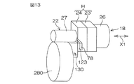
次いで、図11の実施の形態は、伝達機構としての減速機構19の従動側部材がウォームホイールではなく、はすばギヤである場合を示している。この場合、従動ギヤ収容ハウジング280は、電動モータ18の回転軸37の軸方向X1とは平行な中心軸線を有する筒状のハウジングとなる。
熱伝導部材130の一端121がヒートシンク123に近接し、熱伝導部材130の他端122は、隣接ハウジングとしての従動ギヤ収容ハウジング280の端面に熱伝導可能に接続されている。
Next, the embodiment of FIG. 11 shows a case where the driven member of the
One
熱伝導部材130は、制御ハウジングHの第2のハウジング24から隣接ハウジングとしての従動ギヤ収容ハウジング280へ向けて、すなわち、電動モータ18の回転軸37の軸方向X1とは平行な方向に、所定長さL(m)で延び均一な断面を有する部材である。 熱伝導部材130の断面積をA(m2 )、熱伝導率をρ(W/mK)とし、発熱要素の平均損失をB(W/10°C) としたときに、下記式(1)が成立するようにしてある。
The
(A2 /L)<(1/ρ)×B …(1)
この場合、熱伝導部材130の断面積Aと長さLを、十分な伝熱、放熱を発揮できる最適な設定値に設計することが可能である。
また、図13に示すように、熱伝導部材130が、隣接ハウジングとしての従動ギヤ収容ハウジング280の端面の一部に沿って延びていれば、熱伝導面積を広く確保できるので、放熱性をより高めることができる。特に、図14に示すように、熱伝導部材130が隣接ハウジングとしての従動ギヤ収容ハウジング280の外周面280aの概ね全周に沿って延びる部分131を有していれば、伝熱性および放熱性をより一層高めることができる。
(A 2 / L) <(1 / ρ) × B (1)
In this case, the cross-sectional area A and the length L of the
Further, as shown in FIG. 13, if the
本発明は、以上の実施形態の内容に限定されるものではなく、請求項記載の範囲内において種々の変更が可能である。例えば、上述の実施形態では、いわゆるコラムアシスト式の電動パワーステアリング装置に本発明が適用された例について説明したが、これに限らず、いわゆるピニオンアシスト式の電動パワーステアリング装置や、いわゆるラックアシスト式の電動パワーステアリング装置に、本発明を適用してもよい。 The present invention is not limited to the contents of the above embodiments, and various modifications can be made within the scope of the claims. For example, in the above-described embodiment, an example in which the present invention is applied to a so-called column assist type electric power steering apparatus has been described. The present invention may be applied to the electric power steering apparatus.
また、上述の実施形態では、本発明が、電動モータの出力を操舵補助力として出力する電動パワーステアリング装置に適用された例について説明したが、これに限らない。例えば、操舵部材の操舵角に対する転舵輪の転舵角の比を変更可能な伝達比可変機構を備え、伝達比可変機構を駆動するために電動モータの出力を用いる伝達比可変式の車両用操舵装置や、操舵部材と転舵輪との機械的な連結が解除され、転舵輪を電動モータの出力で操向するステア・バイ・ワイヤ式の車両用操舵装置等に、本発明を適用してもよい。 In the above-described embodiment, the example in which the present invention is applied to the electric power steering apparatus that outputs the output of the electric motor as the steering assist force has been described, but the present invention is not limited thereto. For example, a transmission ratio variable mechanism that includes a transmission ratio variable mechanism capable of changing a ratio of a steered wheel turning angle to a steering angle of a steering member, and that uses an output of an electric motor to drive the transmission ratio variable mechanism, is used for vehicle steering. Even if the present invention is applied to a device, a steer-by-wire type vehicle steering device in which the mechanical connection between the steering member and the steered wheel is released and the steered wheel is steered by the output of the electric motor, etc. Good.
また、ECU12のパワー基板78および制御基板79の少なくとも一部を樹脂でモールドするようにしてもよい。
また、上述の実施形態では、電動モータ18として、ブラシレスモータを用いる例について説明したが、これに限らず、ブラシレスモータ以外のモータを、電動モータ18として用いてもよい。
Further, at least a part of the
In the above-described embodiment, an example in which a brushless motor is used as the
1…電動パワーステアリング装置(車両用操舵装置)、4…転舵機構、5…操舵補助機構、6…ステアリングシャフト、11…トルクセンサ(操舵状態検出センサ)、12…ECU(制御装置)、18…電動モータ、19…減速機構(伝達機構)、20…ウォーム軸(駆動側部材)、21…ウォームホイール(従動側部材)、22…ギヤハウジング(伝達機構が収容されたハウジング)、23…第1のハウジング、24,24A…第2のハウジング、25…モータハウジング、26…モータハウジング本体、27…駆動ギヤ収容ハウジング、28,280…従動ギヤ収容ハウジング(隣接ハウジング)、35…センサハウジング(操舵状態検出センサが収容されたハウジング)、37…回転軸、70…モータ室、78…パワー基板、79…制御基板、H…制御ハウジング、100…収容室、101…第1の内壁面、102…第2の内壁面、120,130…熱伝導部材、121…一端、122…他端、123…ヒートシンク、X1…(回転軸の)軸方向 DESCRIPTION OF SYMBOLS 1 ... Electric power steering device (vehicle steering device), 4 ... Steering mechanism, 5 ... Steering assist mechanism, 6 ... Steering shaft, 11 ... Torque sensor (steering state detection sensor), 12 ... ECU (control device), 18 ... Electric motor, 19 ... Deceleration mechanism (transmission mechanism), 20 ... Worm shaft (drive side member), 21 ... Worm wheel (driven side member), 22 ... Gear housing (housing in which transmission mechanism is accommodated), 23 ... No. 1 housing, 24, 24A ... second housing, 25 ... motor housing, 26 ... motor housing body, 27 ... drive gear housing, 28, 280 ... driven gear housing (adjacent housing), 35 ... sensor housing (steering) A housing in which a state detection sensor is accommodated), 37... Rotating shaft, 70... Motor chamber, 78. Substrate, H ... control housing, 100 ... storage chamber, 101 ... first inner wall surface, 102 ... second inner wall surface, 120, 130 ... heat conducting member, 121 ... one end, 122 ... other end, 123 ... heat sink, X1 ... Axial direction (of rotation axis)
Claims (6)
この制御装置を収容する収容室を区画する制御ハウジングと、
この制御ハウジングに対して電動モータとは反対側に隣接する隣接ハウジングと、
制御ハウジングおよび隣接ハウジングの間に配置された熱伝導部材とを備え、
この熱伝導部材の一端が、制御装置の発熱要素に熱伝導可能に近接し、他端が隣接ハウジングに熱伝導可能に接続されており、
上記制御ハウジングは、収容室の一部を区画し且つ電動モータの回転軸の軸方向に対向する第1および第2の内壁面を含み、第1の内壁面は電動モータに相対的に近くに配置されるとともに、第2の内壁面は電動モータから相対的に遠くに配置され、
上記制御装置の発熱要素は、第2の内壁面に熱伝導可能に取り付けられたパワー基板に実装されており、
熱伝導部材の上記一端は、第2の内壁面に連続するヒートシンクに熱伝導可能に接続されていることを特徴とする車両用操舵装置。 A control device for controlling the driving of the electric motor;
A control housing that divides a storage chamber for storing the control device;
An adjacent housing adjacent to the control housing opposite to the electric motor;
A heat conducting member disposed between the control housing and the adjacent housing,
One end of the heat conducting member is adjacent to the heat generating element of the control device so as to be able to conduct heat, and the other end is connected to the adjacent housing so as to be able to conduct heat ,
The control housing includes first and second inner wall surfaces that define a part of the storage chamber and face the axial direction of the rotation shaft of the electric motor, and the first inner wall surface is relatively close to the electric motor. And the second inner wall surface is disposed relatively far from the electric motor,
The heating element of the control device is mounted on a power board attached to the second inner wall surface so as to be capable of conducting heat,
The vehicle steering apparatus according to claim 1, wherein the one end of the heat conducting member is connected to a heat sink continuous with the second inner wall surface so as to conduct heat .
上記隣接ハウジングは、上記従動側部材が収容された筒状のハウジングを含み、
上記熱伝導部材は、上記従動側部材が収容された上記ハウジングの端面または外周面に沿って延びていることを特徴とする車両用操舵装置。 In claim 2 , the transmission mechanism includes a driving side member and a driven side member driven by the driving side member,
The adjacent housing includes a cylindrical housing in which the driven member is accommodated,
The vehicle steering apparatus, wherein the heat conducting member extends along an end surface or an outer peripheral surface of the housing in which the driven member is accommodated.
熱伝導部材の断面積をA、熱伝導率をρとし、発熱要素の平均損失をBとしたときに、下記式が成立するようにしてあることを特徴とする車両用操舵装置。
(A2 /L)<(1/ρ)×B In any one of Claims 1-5 , the said heat conductive member contains the member which has a uniform cross section extended by predetermined length L toward the adjacent housing from a control housing,
A vehicle steering apparatus characterized in that the following equation is established, where A is the cross-sectional area of the heat conducting member, ρ is the heat conductivity, and B is the average loss of the heat generating elements.
(A 2 / L) <(1 / ρ) × B
Priority Applications (4)
| Application Number | Priority Date | Filing Date | Title |
|---|---|---|---|
| JP2008031109A JP5397652B2 (en) | 2008-02-12 | 2008-02-12 | Vehicle steering system |
| US12/867,488 US8342287B2 (en) | 2008-02-12 | 2009-02-10 | Vehicle steering apparatus |
| PCT/JP2009/000529 WO2009101794A1 (en) | 2008-02-12 | 2009-02-10 | Vehicle steering device |
| EP09709572.3A EP2256016B1 (en) | 2008-02-12 | 2009-02-10 | Vehicle steering device |
Applications Claiming Priority (1)
| Application Number | Priority Date | Filing Date | Title |
|---|---|---|---|
| JP2008031109A JP5397652B2 (en) | 2008-02-12 | 2008-02-12 | Vehicle steering system |
Publications (2)
| Publication Number | Publication Date |
|---|---|
| JP2009190476A JP2009190476A (en) | 2009-08-27 |
| JP5397652B2 true JP5397652B2 (en) | 2014-01-22 |
Family
ID=40956826
Family Applications (1)
| Application Number | Title | Priority Date | Filing Date |
|---|---|---|---|
| JP2008031109A Expired - Fee Related JP5397652B2 (en) | 2008-02-12 | 2008-02-12 | Vehicle steering system |
Country Status (4)
| Country | Link |
|---|---|
| US (1) | US8342287B2 (en) |
| EP (1) | EP2256016B1 (en) |
| JP (1) | JP5397652B2 (en) |
| WO (1) | WO2009101794A1 (en) |
Families Citing this family (12)
| Publication number | Priority date | Publication date | Assignee | Title |
|---|---|---|---|---|
| JP5736180B2 (en) * | 2011-01-11 | 2015-06-17 | 株式会社安川電機 | Rotating device |
| JP5776626B2 (en) * | 2011-08-26 | 2015-09-09 | 日本精工株式会社 | Electric power steering device |
| JP5967425B2 (en) * | 2012-06-27 | 2016-08-10 | 株式会社ジェイテクト | Electric power steering device |
| JP6024673B2 (en) * | 2012-10-29 | 2016-11-16 | 日本精工株式会社 | Electric power steering device |
| JPWO2015001684A1 (en) * | 2013-07-03 | 2017-02-23 | 三菱電機株式会社 | Electric power steering device |
| JP6026972B2 (en) * | 2013-08-07 | 2016-11-16 | アスモ株式会社 | Reducer motor |
| JP5907152B2 (en) * | 2013-11-29 | 2016-04-20 | 株式会社デンソー | Drive device |
| EP3093202B1 (en) | 2013-12-25 | 2019-09-18 | Mitsuba Corporation | Wiper device |
| US20160318483A1 (en) * | 2013-12-25 | 2016-11-03 | Mitsuba Corporation | Wiper motor |
| US20160322921A1 (en) | 2013-12-25 | 2016-11-03 | Mitsuba Corporation | Brushless motor, wiper apparatus, motor apparatus, and control method for motor apparatus |
| KR101993295B1 (en) * | 2017-12-19 | 2019-06-26 | 주식회사 만도 | Reducer of Electric Power Steering Apparatus |
| JP7177758B2 (en) * | 2019-08-29 | 2022-11-24 | 日立Astemo株式会社 | steering device |
Family Cites Families (14)
| Publication number | Priority date | Publication date | Assignee | Title |
|---|---|---|---|---|
| GB2295590B (en) * | 1994-11-30 | 1999-01-20 | Nsk Ltd | Electric power steering apparatus |
| JPH08188164A (en) * | 1995-01-11 | 1996-07-23 | Nippon Seiko Kk | Electric powered steering device |
| JP3538944B2 (en) * | 1995-03-24 | 2004-06-14 | 株式会社デンソー | Electric power steering device |
| JP3886278B2 (en) | 1998-12-25 | 2007-02-28 | カヤバ工業株式会社 | Electric power steering device |
| JP2000190586A (en) * | 1998-12-27 | 2000-07-11 | Copyer Co Ltd | Printer |
| JP3774624B2 (en) * | 2000-10-18 | 2006-05-17 | 三菱電機株式会社 | Electric power steering device |
| JP2003182606A (en) * | 2001-12-17 | 2003-07-03 | Toyoda Mach Works Ltd | Electric power steering system |
| JP2004009896A (en) * | 2002-06-06 | 2004-01-15 | Koyo Seiko Co Ltd | Steering device |
| JP3922196B2 (en) * | 2002-08-09 | 2007-05-30 | 株式会社デンソー | Electric power steering device |
| US6851509B2 (en) * | 2002-08-09 | 2005-02-08 | Denso Corporation | Easy-to-assemble structure of electric power steering device |
| JP4615405B2 (en) * | 2004-11-22 | 2011-01-19 | 日立オートモティブシステムズ株式会社 | Motor control device, power steering device and braking force control device |
| EP1920991A1 (en) * | 2005-07-11 | 2008-05-14 | NSK Ltd. | Electric power steering device |
| US7967087B2 (en) * | 2008-06-27 | 2011-06-28 | Caterpillar Sarl | Suspension for a machine |
| US8083014B1 (en) * | 2010-06-09 | 2011-12-27 | Ronald Hall | Undercarriage for a tracked vehicle |
-
2008
- 2008-02-12 JP JP2008031109A patent/JP5397652B2/en not_active Expired - Fee Related
-
2009
- 2009-02-10 WO PCT/JP2009/000529 patent/WO2009101794A1/en active Application Filing
- 2009-02-10 US US12/867,488 patent/US8342287B2/en not_active Expired - Fee Related
- 2009-02-10 EP EP09709572.3A patent/EP2256016B1/en not_active Not-in-force
Also Published As
| Publication number | Publication date |
|---|---|
| WO2009101794A1 (en) | 2009-08-20 |
| EP2256016A1 (en) | 2010-12-01 |
| US8342287B2 (en) | 2013-01-01 |
| EP2256016A4 (en) | 2011-11-09 |
| US20100320026A1 (en) | 2010-12-23 |
| JP2009190476A (en) | 2009-08-27 |
| EP2256016B1 (en) | 2014-12-17 |
Similar Documents
| Publication | Publication Date | Title |
|---|---|---|
| JP5397652B2 (en) | Vehicle steering system | |
| JP5397658B2 (en) | Vehicle steering apparatus and subassembly transfer method | |
| JP5316839B2 (en) | Motor and vehicle steering apparatus including the same | |
| US8408353B2 (en) | Vehicle steering apparatus | |
| JP5071728B2 (en) | Motor control device and vehicle steering apparatus provided with the same | |
| JP2009078690A (en) | Electrical power steering device | |
| JP5397653B2 (en) | Vehicle steering system | |
| JP2010280245A (en) | Steering device for vehicle | |
| JP5397654B2 (en) | Vehicle steering system | |
| JP5397657B2 (en) | Vehicle steering system | |
| JP5234331B2 (en) | Vehicle steering system | |
| JP2011031755A (en) | Motor unit for electric power-steering and electric power-steering device | |
| JP5967425B2 (en) | Electric power steering device | |
| JP5196237B2 (en) | Vehicle steering system | |
| JP5299664B2 (en) | Vehicle steering system | |
| JP2009190477A (en) | Steering device for vehicle | |
| JP5397659B2 (en) | Vehicle steering system | |
| JP5299665B2 (en) | Vehicle steering system | |
| JP5158421B2 (en) | Vehicle steering system | |
| JP2008290530A (en) | Electric power steering device | |
| JP5970923B2 (en) | Electric power steering device | |
| JP2013187990A (en) | Control device of electric motor and vehicle steering gear including the same |
Legal Events
| Date | Code | Title | Description |
|---|---|---|---|
| A621 | Written request for application examination |
Free format text: JAPANESE INTERMEDIATE CODE: A621 Effective date: 20110120 |
|
| A521 | Request for written amendment filed |
Free format text: JAPANESE INTERMEDIATE CODE: A523 Effective date: 20110808 |
|
| A131 | Notification of reasons for refusal |
Free format text: JAPANESE INTERMEDIATE CODE: A131 Effective date: 20130228 |
|
| A521 | Request for written amendment filed |
Free format text: JAPANESE INTERMEDIATE CODE: A523 Effective date: 20130419 |
|
| TRDD | Decision of grant or rejection written | ||
| A01 | Written decision to grant a patent or to grant a registration (utility model) |
Free format text: JAPANESE INTERMEDIATE CODE: A01 Effective date: 20130926 |
|
| A61 | First payment of annual fees (during grant procedure) |
Free format text: JAPANESE INTERMEDIATE CODE: A61 Effective date: 20131009 |
|
| R150 | Certificate of patent or registration of utility model |
Ref document number: 5397652 Country of ref document: JP Free format text: JAPANESE INTERMEDIATE CODE: R150 Free format text: JAPANESE INTERMEDIATE CODE: R150 |
|
| LAPS | Cancellation because of no payment of annual fees |