WO2009101794A1 - Vehicle steering device - Google Patents
Vehicle steering device Download PDFInfo
- Publication number
- WO2009101794A1 WO2009101794A1 PCT/JP2009/000529 JP2009000529W WO2009101794A1 WO 2009101794 A1 WO2009101794 A1 WO 2009101794A1 JP 2009000529 W JP2009000529 W JP 2009000529W WO 2009101794 A1 WO2009101794 A1 WO 2009101794A1
- Authority
- WO
- WIPO (PCT)
- Prior art keywords
- housing
- heat
- electric motor
- steering
- shaft
- Prior art date
Links
Images


Classifications
-
- B—PERFORMING OPERATIONS; TRANSPORTING
- B62—LAND VEHICLES FOR TRAVELLING OTHERWISE THAN ON RAILS
- B62D—MOTOR VEHICLES; TRAILERS
- B62D5/00—Power-assisted or power-driven steering
- B62D5/04—Power-assisted or power-driven steering electrical, e.g. using an electric servo-motor connected to, or forming part of, the steering gear
- B62D5/0403—Power-assisted or power-driven steering electrical, e.g. using an electric servo-motor connected to, or forming part of, the steering gear characterised by constructional features, e.g. common housing for motor and gear box
- B62D5/0406—Power-assisted or power-driven steering electrical, e.g. using an electric servo-motor connected to, or forming part of, the steering gear characterised by constructional features, e.g. common housing for motor and gear box including housing for electronic control unit
-
- B—PERFORMING OPERATIONS; TRANSPORTING
- B62—LAND VEHICLES FOR TRAVELLING OTHERWISE THAN ON RAILS
- B62D—MOTOR VEHICLES; TRAILERS
- B62D5/00—Power-assisted or power-driven steering
- B62D5/04—Power-assisted or power-driven steering electrical, e.g. using an electric servo-motor connected to, or forming part of, the steering gear
- B62D5/0409—Electric motor acting on the steering column
-
- H—ELECTRICITY
- H02—GENERATION; CONVERSION OR DISTRIBUTION OF ELECTRIC POWER
- H02K—DYNAMO-ELECTRIC MACHINES
- H02K11/00—Structural association of dynamo-electric machines with electric components or with devices for shielding, monitoring or protection
- H02K11/30—Structural association with control circuits or drive circuits
- H02K11/33—Drive circuits, e.g. power electronics
-
- H—ELECTRICITY
- H02—GENERATION; CONVERSION OR DISTRIBUTION OF ELECTRIC POWER
- H02K—DYNAMO-ELECTRIC MACHINES
- H02K7/00—Arrangements for handling mechanical energy structurally associated with dynamo-electric machines, e.g. structural association with mechanical driving motors or auxiliary dynamo-electric machines
- H02K7/10—Structural association with clutches, brakes, gears, pulleys or mechanical starters
- H02K7/116—Structural association with clutches, brakes, gears, pulleys or mechanical starters with gears
- H02K7/1163—Structural association with clutches, brakes, gears, pulleys or mechanical starters with gears where at least two gears have non-parallel axes without having orbital motion
- H02K7/1166—Structural association with clutches, brakes, gears, pulleys or mechanical starters with gears where at least two gears have non-parallel axes without having orbital motion comprising worm and worm-wheel
-
- H—ELECTRICITY
- H02—GENERATION; CONVERSION OR DISTRIBUTION OF ELECTRIC POWER
- H02K—DYNAMO-ELECTRIC MACHINES
- H02K9/00—Arrangements for cooling or ventilating
- H02K9/22—Arrangements for cooling or ventilating by solid heat conducting material embedded in, or arranged in contact with, the stator or rotor, e.g. heat bridges
- H02K9/223—Heat bridges
-
- H—ELECTRICITY
- H02—GENERATION; CONVERSION OR DISTRIBUTION OF ELECTRIC POWER
- H02K—DYNAMO-ELECTRIC MACHINES
- H02K9/00—Arrangements for cooling or ventilating
- H02K9/22—Arrangements for cooling or ventilating by solid heat conducting material embedded in, or arranged in contact with, the stator or rotor, e.g. heat bridges
- H02K9/227—Heat sinks
Definitions
- the present invention relates to a vehicle steering apparatus.
- An electric power steering device as a vehicle steering device assists a driver's steering with an electric motor. That is, the steering state of the steering member is detected by various sensors and the like, and the control device controls the electric motor based on the detection result of the steering state and the like, so that a steering assist force is applied to the steering mechanism.
- the control device controls the electric motor based on the detection result of the steering state and the like, so that a steering assist force is applied to the steering mechanism.
- the axial direction of the electric motor it has been proposed to arrange a control device between the electric motor and the speed reduction mechanism (see, for example, Patent Document 1).
- a common case is interposed between the motor housing and the gear housing.
- a motor chamber is defined between the case and the motor housing, and a controller chamber is defined between the case and the gear housing.
- An object of the present invention is to provide a vehicle steering apparatus that is small in size and excellent in heat dissipation.
- a preferred embodiment of the present invention includes a control device that includes a heat generating element and controls driving of an electric motor, a control housing that defines a storage chamber that houses the control device, and sandwiches the control housing. And an adjacent housing adjacent to the control housing and a heat conducting member, the heat conducting member being close to the heat generating element of the control device so as to be capable of conducting heat, and A connected portion connected to the adjacent housing so as to conduct heat.
- the heat from the heat generating element of the control device is not radiated to the adjacent housing adjacent to the opposite side of the electric motor via the heat conducting member, not to the housing of the electric motor that generates heat. Therefore, the heat dissipation can be remarkably improved. Therefore, for example, the heat sink can be reduced in size, and as a result, a vehicle steering apparatus that is small and has good heat dissipation can be realized.
- the heat conducting member a member having high thermal conductivity such as aluminum or copper is preferably used.
- the heat conducting member and the adjacent housing can be integrally formed of a single material.
- a heat pipe as a heat conductive member, or a heat conductive structure material using a heat pipe (for example, a heat lane in which heat pipes are folded and stacked).
- the control housing includes first and second inner wall surfaces facing in the axial direction of the rotation shaft of the electric motor, and a part of the housing chamber is partitioned by the first and second inner wall surfaces.
- the first inner wall surface is disposed relatively close to the electric motor, and the second inner wall surface is disposed relatively far from the electric motor, and the heating element of the control device Is mounted on a power board attached to the second inner wall surface so as to be capable of conducting heat, and the proximity portion of the heat conducting member is connected to a heat sink continuous with the second inner wall surface so as to be able to conduct heat. If it is, it is preferable.
- a power board on which a heating element such as a switching element is mounted is attached to the second inner wall surface on the side close to the adjacent housing so as to be able to conduct heat.
- the heat of the heat generating element can be efficiently released to the adjacent housing via the power board, the heat sink and the heat conducting member continuous with the second inner wall surface, and the heat dissipation can be improved. Therefore, the heat sink can be miniaturized as much as possible, and the vehicle steering apparatus can be miniaturized.
- a transmission mechanism housing in which a transmission mechanism for transmitting the power of the electric motor to the steering mechanism is accommodated and the adjacent housing includes a housing provided in the transmission mechanism housing.
- the control device typically includes a heating element such as a switching element mounted on the power board.
- the transmission mechanism hardly generates heat. Heat from the heat generating element can be effectively released to the outside of the storage chamber via the housing that stores such a transmission mechanism.
- the transmission mechanism includes a driving member and a driven member driven by the driving member, and the transmission mechanism housing includes a cylindrical driven member housing housing in which the driven member is housed.
- the connected portion of the conductive member is preferably provided along at least one of the outer peripheral surface and the end surface of the driven member housing.
- a cylindrical driven member housing housing that accommodates a driven member that is larger than the driving member can secure a sufficient heat radiation area, so that heat dissipation can be significantly improved.
- a steering state detection sensor for detecting a steering state is further provided, and the adjacent housing includes a sensor housing in which the steering state detection sensor is accommodated.
- heat from a heating element such as a switching element can be effectively released outside the storage chamber via the sensor housing in which the steering state detection sensor is stored.
- at least a part of the heat conducting member is disposed between the control housing and the adjacent housing because the length of the heat conducting path can be shortened.
- the control device is arranged around a central axis of a rotating shaft of the electric motor or an extension of the central axis.
- the space inside the storage chamber can be effectively used for the arrangement of the control device, and consequently the vehicle steering device can be made smaller with respect to the axial direction of the rotating shaft of the electric motor.
- the heat conducting member includes a member extending at a predetermined length L from the control housing toward the adjacent housing. A cross-sectional area of the member extending at the predetermined length L is A, and the predetermined length L is When the thermal conductivity of the extending member is ⁇ and the average loss of the heat generating element is B, it is preferable that the following formula is satisfied.
- FIG. 3 is a schematic perspective view of the steering assist mechanism when the steering assist mechanism is viewed from an angle different from that of FIG. 2. It is an illustration sectional view of a steering auxiliary mechanism cut along the axial direction of an electric motor. It is a typical top view of a power board. It is an enlarged view of the principal part of FIG. It is a typical side view of the principal part of an electric power steering device.
- FIG. 5 is a schematic cross-sectional view of a steering assist mechanism of an electric power steering device as a vehicle steering device according to another embodiment of the present invention.
- FIG. 10 is a schematic side view of a main part of an electric power steering device as a vehicle steering device according to still another embodiment of the present invention.
- FIG. 10 is a schematic side view of a main part of an electric power steering device as a vehicle steering device according to still another embodiment of the present invention.
- FIG. 10 is a schematic side view of a main part of an electric power steering device as a vehicle steering device according to still another embodiment of the present invention. It is a typical perspective view of a heat conductive member.
- FIG. 10 is a schematic side view of a main part of an electric power steering device as a vehicle steering device according to still another embodiment of the present invention.
- FIG. 10 is a schematic side view of a main part of an electric power steering device as a vehicle steering device according to still another embodiment of the present invention.
- SYMBOLS 1 Electric power steering device (vehicle steering device), 4 ... Steering mechanism, 5 ... Steering assist mechanism, 6 ... Steering shaft, 11 ... Torque sensor (steering state detection sensor), 12 ... ECU (control device), 18 ... Electric motor 19, 19A ... Deceleration mechanism (transmission mechanism), 20 ... Worm shaft (drive member), 20A ... Drive member, 21 ... Worm wheel (driven member), 21A ... Drive member, 22, 22A ... Gear housing ( (Housing housing), 23... First housing, 24, 24A... Second housing, 25... Motor housing, 26... Motor housing body, 27. ), 28, 280... Driven gear housing (driven member housing; adjacent housing), 281. Surface, 282 ... Electric power steering device (vehicle steering device), 4 ... Steering mechanism, 5 ... Steering assist mechanism, 6 ... Steering shaft, 11 ... Torque sensor (steering state detection sensor), 12 ... ECU (control device), 18 ... Electric motor 19, 19A ... Dec
- outer peripheral surface 35A ... sensor housing (housing containing a steering state detection sensor; adjacent housing), 37 ... rotating shaft, 70 ... motor chamber, 78 ... power board, 79 ... control board, H ... control housing , 100 ... storage chamber, 101 ... first inner wall surface, 102 ... second inner wall surface, 96, 96A, 96B, 96C, 96D, 96E ... heat conducting member, 97 ... proximity portion, 98, 98A, 98B, 98C , 98D, 98E ... connected portion, 123 ... heat sink, C1 ... central axis line (of rotating shaft), C2 ... extension line, C4 ... central axis line (of driven member), X1 ... axial direction of rotating shaft, A ... Cross-sectional area, B ... average loss, L ... predetermined length
- FIG. 1 is a schematic diagram showing a schematic configuration of an electric power steering apparatus 1 as a vehicle steering apparatus according to an embodiment of the present invention.
- an electric power steering apparatus 1 includes a steering wheel 2 as a steering member, a steering mechanism 4 that steers a steered wheel 3 in conjunction with rotation of the steering wheel 2, and steering of a driver. And a steering assist mechanism 5 for assisting.
- the steering wheel 2 and the steering mechanism 4 are mechanically coupled via a steering shaft 6 and an intermediate shaft 7.
- the steering assist mechanism 5 will be described based on an example in which an assist force (steering assist force) is applied to the steering shaft 3, but the present invention is applied to the pinion shaft described later.
- the present invention can be applied to a structure for giving or an assisting mechanism 5 for giving assist force to a rack shaft, which will be described later.
- the steering shaft 6 extends linearly.
- Steering shaft 6 includes an input shaft 8 connected to steering wheel 2 and an output shaft 9 connected to intermediate shaft 7.
- the input shaft 8 and the output shaft 9 are connected via a torsion bar 10 so as to be relatively rotatable on the same axis. That is, when a steering torque greater than a certain value is input to the steering wheel 2, the input shaft 8 and the output shaft 9 rotate in the same direction while rotating relative to each other.
- a torque sensor 11 as a steering state detection sensor disposed around the steering shaft 6 detects the steering torque input to the steering wheel 2 based on the relative rotational displacement amounts of the input shaft 8 and the output shaft 9.
- the torque detection result of the torque sensor 11 is input to an ECU 12 (Electronic Control Unit) as a control device.
- the vehicle speed detection result from the vehicle speed sensor 90 is input to the ECU 12.
- the intermediate shaft 7 connects the steering shaft 6 and the steering mechanism 4.
- the steered mechanism 4 includes a rack and pinion mechanism including a pinion shaft 13 and a rack shaft 14 as a steered shaft.
- a steered wheel 3 is connected to each end of the rack shaft 14 via a tie rod 15 and a knuckle arm (not shown).
- the pinion shaft 13 is connected to the intermediate shaft 7.
- the pinion shaft 13 rotates in conjunction with the steering of the steering wheel 2.
- a pinion 16 is provided at the tip (lower end in FIG. 1) of the pinion shaft 13.
- the rack shaft 14 extends linearly along the left-right direction of the automobile.
- a rack 17 that meshes with the pinion 16 is formed in the middle of the rack shaft 14 in the axial direction.
- the steering assist mechanism 5 includes an electric motor 18 for assisting steering, and a speed reduction mechanism 19 as a transmission mechanism for transmitting the output torque of the electric motor 18 to the steering mechanism 4.
- a staggered shaft gear mechanism such as a worm gear mechanism, a parallel shaft gear mechanism, or the like can be used.
- a worm gear mechanism is used as the speed reduction mechanism 19.
- the speed reduction mechanism 19 includes a worm shaft 20 as a drive gear (drive member of the transmission mechanism) and a worm wheel 21 as a driven gear (driven member of the transmission mechanism) that meshes with the worm shaft 20.
- the speed reduction mechanism 19 is accommodated in a gear housing 22 as a transmission mechanism housing.
- the worm shaft 20 is connected to a rotating shaft (not shown) of the electric motor 18 through a joint (not shown).
- the worm shaft 20 is rotationally driven by the electric motor 18.
- the worm wheel 21 is connected to the steering shaft 6 so as to be able to rotate together.
- the worm wheel 21 is rotationally driven by the worm shaft 20.
- the electric motor 18 rotationally drives the worm shaft 20
- the worm wheel 21 is rotationally driven by the worm shaft 20
- the worm wheel 21 and the steering shaft 6 rotate together.
- the rotation of the steering shaft 6 is transmitted to the pinion shaft 13 via the intermediate shaft 7.
- the rotation of the pinion shaft 13 is converted into the axial movement of the rack shaft 14.
- the steered wheel 3 is steered. That is, the steered wheels 3 are steered by rotating the worm shaft 20 by the electric motor 18.
- the electric motor 18 is controlled by the ECU 12.
- the ECU 12 controls the electric motor 18 based on the torque detection result from the torque sensor 11, the vehicle speed detection result from the vehicle speed sensor 90, and the like. Specifically, the ECU 12 determines a target assist amount using a map in which the relationship between the torque and the target assist amount is stored for each vehicle speed, and controls the assist force generated by the electric motor 18 to approach the target assist amount. To do.
- FIG. 2 and 3 are schematic perspective views of the steering assist mechanism 5, respectively, and are views of the steering assist mechanism 5 seen from different angles.
- the main feature of the present embodiment is that the control housing H for accommodating the ECU 12 as the control device is in contact with each other as shown in FIG. 2 and FIG. Or a state in which the ends of the two are fitted to each other) (the first housing 23 and the second housing 24).
- first housing 23 and the second housing 24 constituting the control housing H for housing the ECU 12 are in contact with each other. That is, the first housing 23 and the second housing 24 are directly engaged, and no other housing is interposed between the housings 23 and 24. As a result, a significant reduction in size is achieved.
- Each of the first housing 23 and the second housing 24 is formed in a substantially square box shape with one end opened. The end portions of the first and second housings 23 and 24 are abutted and fastened to each other by a fixing screw 91.
- the motor housing 25 of the electric motor includes a cylindrical motor housing body 26 and the first housing 23 described above.
- the first housing 23 that is a part of the control housing H for housing the ECU 12 is formed integrally with at least a part of the motor housing 25 of the electric motor 12 from a single material. .
- at least a part of the motor housing 25 and a part of the control housing H for housing the ECU 12 are combined.
- the gear housing 22 includes a driving gear housing 27 as a cylindrical driving member housing housing in which the worm shaft 20 is housed, and a driven gear housing as a cylindrical driven member housing housing in which the worm wheel 21 is housed. 28 and the second housing 24 described above.
- the second housing 24, which is a part of the control housing H for housing the ECU 12 is integrated with the driving gear housing 27 and the driven gear housing 28 of the gear housing 22 from a single material. Is formed. In other words, a part of the gear housing 22 and a part of the control housing H for housing the ECU 12 are combined.
- a cylindrical projection 93 projects from an outer periphery 92 a of the outer peripheral wall 92 as a side wall of the first housing 23, and an electrical connector 94 facing the outside of the first housing 23 is formed in the cylindrical projection 93. Is arranged.
- the electrical connector 94 is provided with terminals for supplying power from the battery to the ECU 12 and terminals for inputting and outputting signals from the outside.
- FIG. 4 is a cross-sectional view of the main part of the electric power steering apparatus
- the worm wheel 21 as the driven member of the speed reduction mechanism 19 (transmission mechanism) and the electric connector 94 are driven by the speed reduction mechanism 19 (transmission mechanism).
- the central axis C3 of the worm shaft 20 as a member is disposed on the same side with respect to a plane Q1 parallel to the central axis 21a of the worm wheel 21.
- the electrical connector 94 and the driven gear housing 28 that serve as the projecting portion project to the same side.
- FIG. 3 a layout in which at least a part of each of electrical connector 94 and driven gear housing 28 overlap each other when viewed along an axial direction X1 of a rotating shaft 37 (described later) of electric motor 18.
- the electrical connector 94 and the sensor housing 35 have a layout in which at least a part of each other overlaps each other. Thereby, substantial miniaturization and space saving can be achieved, and the mounting property to the vehicle is improved.
- the first housing 23 of the motor housing 25 is formed of, for example, an aluminum alloy (for example, a cast product or a cold forging product), and the steering assist mechanism 5 is reduced in weight.
- the gear housing 22 including the drive gear housing 27, the driven gear housing 28 and the second housing 24 is formed of, for example, an aluminum alloy (for example, a cast product or a cold forging product). The weight is reduced. Further, for example, a non-magnetic sheet metal is used for the motor housing body 26 of the motor housing 25.
- the motor housing body 26 includes a cylindrical peripheral wall 29, a bottom wall 30 that closes one end of the peripheral wall 29, and an annular flange 31 that protrudes radially outward from the other end of the peripheral wall 29.
- a bracket 32 projecting radially outward from a part of the annular flange 31 in the circumferential direction is provided.
- the motor housing body 26 and the first housing 23 are integrally fixed by screwing the fixing screw 34 inserted through the screw insertion hole 33 of the bracket 32 into the screw hole of the first housing 23. Since the screw insertion hole 33 is formed as a long hole extending in the circumferential direction of the motor housing body 26, the circumferential position of the motor housing body 26 can be adjusted with respect to the first housing 23. .
- first housing 23 and the second housing 24 constituting the control housing H for housing the ECU 12 are fixed to each other using a fixing screw 91.
- a cylindrical sensor housing 35 in which the torque sensor 11 is accommodated is connected to the driven gear accommodating housing 28 of the gear housing 22.
- the driven gear housing 28 and the sensor housing 35 are fixed to each other using a fixing screw 36.
- the steering shaft 6 is inserted into the cylindrical driven gear housing 28 and the sensor housing 35.
- a housing chamber 100 that houses ECU 12 as a control device by first housing 23 that is motor housing 25 of electric motor 18 and second housing 24 that is in contact with first housing 23. Is formed. The end surfaces of the first housing 23 and the second housing 24 are abutted with each other, and the end surfaces are sealed by an annular seal member 95.
- the first housing 23 includes a first inner wall surface 101 that defines a part of the storage chamber 100
- the second housing 24 includes a second inner wall surface 102 that partitions a part of the storage chamber 100.
- the first inner wall surface 101 and the second inner wall surface 102 are opposed to the axial direction X1 of the rotating shaft 37 of the electric motor 18.
- the second inner wall surface 102 of the second housing 24 includes an annular plane, and the annular plane is the central axis C1 of the rotating shaft 37 of the electric motor 18 or an extension line C2 of the central axis C1 (usually , Which coincides with the central axis C3 of the worm shaft 20) and surrounds the central axis C1 or the extension line C2.
- the second inner wall surface 102 is formed with a flat seat portion 103 that protrudes toward the housing chamber 100 from the annular plane, and the bottom of the seat portion 103 is a thick heat sink 123.
- the power substrate 78 is received by the seat portion 103 of the second inner wall surface 102 so as to be able to conduct heat.
- a power circuit for driving the electric motor 18 is mounted on the power board 78, and the power circuit includes a switching element such as a FET (Field Effect Transistor) as a heat generating element.
- the extension surface P1 of the seat portion 103 of the second inner wall surface 102 is a cylindrical surface P2 formed by the main part of the outer peripheral surface 28a of the cylindrical driven gear housing 28 as an adjacent housing adjacent to the control housing H, and FIG. So that they touch or cross. Further, the ECU 12 as the control device is disposed around the central axis C1 or the extension line C2 of the rotating shaft 37.
- the rotating shaft 37 and the worm shaft 20 of the electric motor 18 are arranged side by side on the same axis.
- the rotating shaft 37 and the worm shaft 20 are connected so as to be able to transmit power via a joint 38 interposed therebetween.
- the joint 38 is interposed between the input member 39 and the output member 40, the annular input member 39 that rotates together with the rotating shaft 37 of the electric motor 18, the annular output member 40 that rotates along with the worm shaft 20, and the input member 40. 39 and an output elastic member 41 for connecting the output member 40 so that power can be transmitted.
- the worm shaft 20 is accommodated in the drive gear accommodation hole 42 of the drive gear accommodation housing 27 of the gear housing 22.
- the worm shaft 20 has a first end portion 20 a and a second end portion 20 b, and a worm 20 c is formed at an intermediate portion in the axial direction of the worm shaft 20.
- the first end portion 20a of the worm shaft 20 can be rotated by a first bearing 45 held by a bearing holding portion 44 on the inner periphery of one end (end portion on the electric motor 18 side) of the drive gear accommodation hole 42. It is supported.
- the second end portion 20 b of the worm shaft 20 is rotatably supported by a second bearing 47 held by an inner peripheral bearing holding portion 46 at the other end of the drive gear accommodation hole 42.
- the first bearing 45 is a rolling bearing having an inner ring 48, an outer ring 49, and a plurality of rolling elements 50 interposed between the inner ring 48 and the outer ring 49.
- the inner ring 48 is held by the first end 20a of the worm shaft 20 so as to be able to rotate together.
- One end face of the inner ring 48 is in contact with a positioning step provided on the outer periphery of the worm shaft 20.
- a small-diameter protruding shaft 51 is extended from the first end 20 a of the worm shaft 20.
- the projecting shaft 51 is fitted with the output member 40 of the joint 38 so that the output member 40 can rotate along with the shaft 38 and cannot move in the axial direction.
- the output member 40 is in contact with the other end surface of the inner ring 48.
- An inner ring 48 is sandwiched between the positioning step portion of the worm shaft 20 and the output member 40. Thereby, the axial movement of the inner ring 48 relative to the worm shaft 20 is restricted.
- the fixing member 52 includes a cylindrical main body 52a having a screw formed on the outer periphery, an inner flange 52b extending radially inward from one end of the main body 52a, and an outer extending radially outward from the other end of the main body 52a. And a flange 52c.
- the inner flange 52 b presses the other end surface of the outer ring 49. Further, the outer flange 52c is pressed against the second inner wall surface 102 of the second housing 24 that divides the accommodation chamber of the ECU 12, and thereby the locking of the fixing member 52 is achieved.
- the second bearing 47 is composed of a rolling bearing having an inner ring 53, an outer ring 54, and a plurality of rolling elements 55 interposed between the inner ring 53 and the outer ring 54.
- the inner ring 53 is held by the second end 20b of the worm shaft 20 so as to be able to rotate together.
- One end face of the inner ring 53 is in contact with a positioning step provided on the outer periphery of the worm shaft 20. Thereby, the axial movement (movement toward the first bearing 45) of the inner ring 53 with respect to the worm shaft 20 is restricted.
- a screw portion 56 is formed at the entrance portion of the drive gear accommodation hole 42 adjacent to the bearing holding portion 46 of the drive gear accommodation hole 42, and the first and second bearings 45 and 47 are formed in the screw portion 56.
- a preload application member 57 for applying preload in a lump is screwed in.
- the preload applying member 57 has a disk-shaped main body 58, and a screw portion 59 that is screwed into the screw portion 56 is formed on the outer periphery of the main body 58.
- An annular convex portion 60 that presses one end surface of the outer ring 54 of the second bearing 47 is formed on one end surface of the main body 58.
- the first and second bearings 45 and 47 that support the first and second end portions 20a and 20b of the worm shaft 20 are both configured by known seal bearings. Specifically, a seal member 63 that seals between the inner ring and the outer ring is provided on both sides in the axial direction X1 of the rolling element, and the seal member 63 is fixed to either the inner ring or the outer ring. Further, the seal member 63 has a lip that is in sliding contact with the other.
- first and second bearings 45 and 47 that support both ends of the worm shaft 20 are constituted by seal bearings, lubricant such as grease in the gear housing 22 leaks to the accommodation chamber 100 side in which the ECU 12 is accommodated. I don't get out.
- a liquid packing may be interposed between the screw portion on the outer periphery of the main body 52a of the fixing member 52 and the screw portion screwed into the screw portion.
- a brushless motor is used as the electric motor 18.
- the electric motor 18 includes the motor housing 25, and a rotor 64 and a stator 65 accommodated in the motor housing 25.
- the rotor 64 includes an annular rotor core 66 attached to the outer periphery of the rotary shaft 37 so as to be able to rotate along with the rotor shaft 67, and a rotor magnet 67 made of, for example, an annular permanent magnet attached to the outer periphery of the rotor core 66 so as to be able to rotate along with the rotor.
- a plurality of magnetic poles are arranged side by side in the circumferential direction. These magnetic poles are configured so that the N pole and the S pole are alternately switched in the circumferential direction of the rotor 64.
- the stator 65 is fixed to the inner periphery of the motor housing body 26 of the motor housing 25.
- the stator 65 includes a stator core 68 fixed to the inner periphery of the motor housing body 26 and a plurality of coils 69.
- Stator core 68 includes an annular yoke and a plurality of teeth protruding radially inward from the inner periphery of the yoke. Each coil 69 is wound around a corresponding tooth.
- a bus bar 71 having an annular shape or a C shape is accommodated in the motor chamber 70 defined by the motor housing body 26 and the first housing 23 of the motor housing 25, a bus bar 71 having an annular shape or a C shape is accommodated.
- the coil 69 wound around each tooth is connected to the bus bar 71.
- the bus bar 71 is a conductive connection material used for a connection portion between each coil 69 and a current application line.
- the bus bar 71 functions as a power distribution member for distributing power from a power supply source (not shown) to each coil 69.
- a rotational position detector 72 for detecting the rotational position of the rotor 64 is accommodated in the motor chamber 70 defined by the motor housing body 26 and the first housing 23 of the motor housing 25.
- the rotational position detection device 72 has a stator 73 fixed to the first housing 23 and a rotor 74 attached to the rotational shaft 37 so as to be able to rotate together.
- a resolver can be used as the rotational position detecting device 72.
- a Hall element can also be used.
- the rotational position detecting device 72 may be disposed between the rotor core 66 of the rotor 64 of the electric motor 18 and the second housing 24. Therefore, as in the present embodiment, it may be arranged in the motor chamber 70, or in a cylindrical portion 89 (described later) provided in the center of the first housing 23 that defines the storage chamber 100 of the ECU 12. It may be arranged.
- the rotary shaft 37 includes third and fourth bearings 75 and 4 held by the first housing 23 that serves as both a part of the motor housing 25 and a part of the housing that houses the ECU 12.
- the bearing 76 is rotatably supported.
- the third and fourth bearings 75 and 76 are constituted by seal bearings having the same configuration as the first and second bearings 45 and 47.
- the first housing 23 that is a part of the control housing H that partitions the storage chamber 100 of the ECU 12 includes a partition wall 77 that partitions the storage chamber 100 and the motor chamber 70 as a bottom wall.
- the partition wall 77 is provided with the first inner wall surface 101.
- a cylindrical projection 104 extends from the vicinity of the outer periphery of the partition wall 77 toward the motor housing body 26, and one end of the motor housing body 26 is fitted to the outer periphery of the cylindrical projection 104.
- the partition wall 77 has a holding hole 105 for holding the outer ring of the third bearing 75 described above.
- a cylindrical projection 106 extending from the partition wall 77 toward the motor housing body 26 is formed.
- the cylindrical protrusion 106 is formed coaxially with the holding hole 105.
- the cylindrical projection 106 is formed with a smaller diameter than the cylindrical projection 104 that engages with the motor housing body 26.
- a stator 73 of the rotational position detecting device 72 is fixed to the inner periphery of the cylindrical protrusion 106.
- a cylindrical portion 89 extending from the partition wall 77 toward the second housing 24 side is formed.
- the cylindrical portion 89 is formed coaxially with the holding hole 105.
- the outer ring of the fourth bearing 76 is held on the inner periphery of the cylindrical portion 89.
- An annular flange 107 extending radially inward is provided at one end of the cylindrical portion 89.
- One end of the outer ring of the fourth bearing 76 abuts on the annular flange 107, so that the axial movement of the outer ring of the fourth bearing 76 with respect to the tubular portion 89 is restricted.
- the inner ring of the fourth bearing 76 is sandwiched between an annular positioning step formed on the outer periphery of the rotating shaft 37 and the end face of the input member 39 of the joint 38. Thereby, the axial movement of the inner ring of the fourth bearing 76 with respect to the rotating shaft 37 is restricted.
- a power board 78 and a control board 79 that constitute a part of the ECU 12 are accommodated and held.
- On the power board 78 at least a part of a power circuit for driving the electric motor 18 is mounted.
- a switching element such as a FET (Field Effect Transistor) as a heating element is mounted.
- the bus bar 71 connected to each coil 69 is connected to the power board 78 via a bus bar terminal 80 that passes through the partition wall 77 of the first housing 23 and enters the housing chamber 100.
- the rotational position detection device 72 is connected to the control board 79 via a bus bar terminal 81 that passes through the partition wall 77 of the first housing 23 and enters the storage chamber 100.
- the input member 39 of the joint 38 has a cylindrical portion 39 a that is fitted to the end portion of the rotating shaft 37 of the electric motor 18 so as to be able to rotate together.
- the control board 79 is disposed around the cylindrical portion 39 a of the input member 39. Specifically, the cylindrical portion 39 a is inserted through the insertion hole 79 a in the center of the control board 79.
- the control board 79 is disposed between the first inner wall surface 101 of the first housing 23 and the power board 78 with respect to the axial direction X1 of the rotating shaft 37 of the electric motor 18.
- the power board 78 and the control board 79 are arranged at a predetermined interval with respect to the axial direction X1 of the rotating shaft 37 of the electric motor 18.
- the accommodation space S 1 formed between the partition wall 77 of the first housing 23 and the control board 79 has a sufficient height with respect to the axial direction X 1 of the rotating shaft 37 of the electric motor 18. is doing.
- tall parts such as capacitors and relays are accommodated in the accommodation space S ⁇ b> 1, and the space in the accommodation chamber 100 is effectively used.
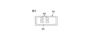
- a power circuit 82 for driving the electric motor 18 is mounted on the power board 78.
- the power circuit 82 mounted on the power board 78 includes a plurality of FETs 83 (Field Effect Transistor) as heat generating elements.
- the power board 78 is composed of a multilayer board on which a circuit is mounted on one side, and the power board 78 composed of the multilayer board is in surface contact with the seat portion 103 connected to the heat sink 123 as shown in FIG. And a high thermal conductive plate 78a.
- a control circuit (not shown) for controlling the power circuit 82 is mounted on the control board 79.
- the control circuit includes a driver that controls each FET 83 of the power circuit 82 and a CPU that controls the driver.
- the ECU 12 has a plurality of capacitors for removing ripples of current flowing through the electric motor 18, relays for cutting off current flowing through the electric motor 18 as necessary, and other non-heat generation.
- Capacitors, relays, and the like as non-heat generating elements constitute a subassembly supported by an annular synthetic resin holder (not shown), and can be collectively attached to the first housing 23. ing.
- the first housing 23 is a substantially square box-shaped member with one end open.
- the first housing 23 includes a generally rectangular box-shaped main body 87 having one end opened.
- the main body 87 has an outer peripheral wall 92 having a substantially quadrangular ring shape and the partition wall 77 as a bottom wall.
- a cylindrical portion 89 extending toward the open side (the second housing 24 side) of the main body 87 is formed at the center of the partition wall 77.
- the outer peripheral wall 92 extends from the outer peripheral edge of the partition wall 77 and surrounds the tubular portion 89.
- the main body 87 and the cylindrical portion 89 are integrally formed of a single member.
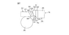
- the drive gear housing 27 and the driven gear housing 28 as adjacent housings face the electric motor 18 with the control housing H interposed therebetween. That is, the drive gear housing 27 and the driven gear housing 28 as adjacent housings are adjacent to the control housing H on the side opposite to the electric motor 18.
- a heat conducting member 96 is provided between the driven gear housing 28 as an adjacent housing and the control housing H.
- the heat conducting member 96 is connected to a power supply 78 on which the FET 83 as the heat generating element is mounted in proximity to the power board 78 so as to be capable of conducting heat, and a driven gear receiving housing 28 serving as the adjacent housing. It has the connection part 98 and the to-be-connected part 99 connected to the drive gear accommodation housing 27 as an adjacent housing so that heat conduction is possible.
- the heat conductive member 96 a member having high thermal conductivity such as aluminum or copper is used.
- the heat conducting member 96 and the driven gear housing 28 as an adjacent housing can be integrally formed of a single material.
- the connecting portion between the second housing 24 of the control housing 28 and the driven gear housing 28 is made thick, and the heat conducting member 96 is constituted by the thick portion.
- the heat conducting member 96 a heat pipe or a heat conducting structural material using a heat pipe (for example, a heat lane in which heat pipes are folded and stacked) can be used.
- the heat conducting member 96 preferably has a connected portion 99 connected to the drive gear housing 27 as an adjacent housing so as to be able to conduct heat.
- the seat portion 103 of the second inner wall surface 102 is in contact with the power substrate 78 having the FET 83 as a heat generating element so as to be able to conduct heat. Therefore, the heat of the FET 83 as the heat generating element is released from the power board 78 to the driven gear housing 28 or the drive gear housing 27 side as the adjacent housing through the heat sink 123 and the heat conducting member 96.
- control housing H is configured by the first housing 23 that is at least a part of the motor housing 25 and the second housing 24 that is in contact with the first housing 23, whereby the accommodation chamber 100 of the ECU 12. Is forming. That is, since another housing is not interposed between the first housing 23 and the second housing 24, the size can be reduced.
- the driven gear housing is not an electric motor 18 that tends to generate heat from the FET 83 as a heat generating element of the ECU 12 but an adjacent housing that is adjacent to the opposite side of the electric motor 18. Since heat is dissipated through the heat conducting member 96 with respect to 28, the heat dissipation can be remarkably improved. Therefore, the heat sink 123 can be reduced in size, and as a result, the electric power steering apparatus 1 that is small and has good heat dissipation can be realized.
- the second inner wall surface 102 of the second housing 24 that divides a part of the storage chamber 100 is orthogonal to the central axis C1 (or an extension line C2 thereof) of the rotating shaft 37 of the electric motor 18 and the central axis. It includes an annular plane that surrounds C1 (or its extension C2). Since the heat sink 123 can be reduced in size as described above, the amount of protrusion of the flat seat 103 provided so as to protrude from the annular plane to form the heat sink 123 into the accommodation chamber 100 is small. That is, there is no unnecessarily large protrusion into the storage chamber 100 in the axial direction X1 of the rotating shaft 37 of the electric motor 18. Therefore, even if the storage chamber 100 is small with respect to the axial direction X1, it is possible to secure a sufficient internal volume as the storage chamber 100. As a result, the electric power steering device 1 can be miniaturized as much as possible. it can.
- the second housing 24 is the gear housing 22 in which the speed reduction mechanism 19 as a transmission mechanism for transmitting the power of the electric motor 18 to the steering mechanism 4 is accommodated, the following advantages are obtained. That is, the ECU 12 typically includes a heating element such as a switching element (FET 83) mounted on the power board 78 as in the present embodiment. On the other hand, the speed reduction mechanism 19 hardly generates heat. The heat from the heat generating element can be effectively released to the outside of the storage chamber 100 through the gear housing 22 in which the speed reduction mechanism 19 is stored.
- a heating element such as a switching element (FET 83) mounted on the power board 78 as in the present embodiment.
- FET 83 switching element
- the extension surface P1 of the seat portion 103 protruding from the annular plane formed by the second inner wall surface 102 is driven as a cylindrical portion surrounding a shaft for transmitting a steering force (corresponding to the steering shaft 6 in this embodiment). 4 is in contact with or intersects with the cylindrical surface P2 formed by the main portion of the outer peripheral surface 28a of the gear housing 28. Accordingly, the storage chamber 100 is disposed sufficiently close to the steering shaft 6 side with respect to the axial direction X1 of the rotating shaft 37 of the electric motor 18, and the electric power steering device 1 is disposed with respect to the axial direction X1 of the rotating shaft 37. It can be made smaller.
- the shaft for transmitting the steering force is not limited to the steering shaft 6 described above, but may be a pinion shaft 13 of a rack and pinion mechanism as the steering mechanism 4 or the rack shaft 14. May be.
- the cylindrical surface formed by the main part of the outer peripheral surface of a cylindrical pinion housing (not shown) surrounding the pinion shaft 13 and the extension surface P1 intersect or contact each other.
- the cylindrical surface formed by the main part of the outer peripheral surface of a cylindrical rack housing (not shown) surrounding the rack shaft 14 and the extension surface P1 intersect or contact each other.
- the ECU 12 as the control device is arranged around the central axis C1 of the rotating shaft 37 of the electric motor 18 or the extension line C2 of the central axis C1, the space inside the accommodation chamber 100 is effectively used for the arrangement of the ECU 12. Therefore, the electric power steering apparatus 1 can be made smaller with respect to the axial direction X1 of the rotating shaft 37.
- the second housing 24 and the gear housing 22 are used together.
- the present invention is not limited to this, and as shown in FIG. 8, the second housing 24A and the sensor housing 35A are used together. May be. That is, the second housing 24A and the sensor housing 35A are integrally formed of a single material.
- the heat from the heat generating elements such as the FET 83 can be effectively released to the outside of the storage chamber 100 through the sensor housing 35A as the adjacent housing in which the torque sensor 11 as the steering state detection sensor is stored.
- the same components as those in FIG. 4 are denoted by the same reference numerals.
- a structure in which a housing that houses a steering angle sensor as a steering state detection sensor that detects a steering angle of the steering wheel 2 and the second housing described above may be used.
- the heat conducting member 96A has a connected portion 98A extending along a part of the outer peripheral surface 28a of the driven gear housing 28 as an adjacent housing, the heat conducting area is increased. Since it can ensure widely, heat dissipation can be improved more.
- the heat conducting member 96B has a connected portion 98B extending along substantially the entire circumference of the outer peripheral surface 28a of the driven gear housing 28 as an adjacent housing, heat transfer and heat dissipation are achieved. The sex can be further enhanced.
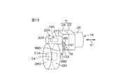
- the speed reduction mechanism 19A as a transmission mechanism has a drive member 20A and a driven member 21A, and the driven member 21A is not a worm wheel but an axial direction X1 of the rotating shaft 37 of the electric motor 18.
- the driven gear housing 280 of the gear housing 22A is a cylindrical housing centered on the central axis C4 of the driven member 21A.
- the proximity portion 97 of the heat conducting member 96C is close to the heat sink 123, and the connected portion 98C of the heat conducting member 96C is connected to the end face 281 of the driven gear housing 280 as an adjacent housing so as to be able to conduct heat.
- the heat conducting member 96C is predetermined from the second housing 24 of the control housing H toward the driven gear housing 280 as an adjacent housing, that is, in a direction parallel to the axial direction X1 of the rotating shaft 37 of the electric motor 18. It is a member having a uniform cross-sectional area A (m 2 ) extending with a length L (m) (see FIG. 12).
- the thermal conductivity of the heat conducting member 96C is ⁇ (W / mK) and the average loss of the heat generating elements is B (W / 10 ° C)
- the following formula (1) is established. (A 2 / L) ⁇ (1 / ⁇ ) ⁇ B (1)
- the cross-sectional area A and the length L of the heat conducting member 96C can be designed to optimum setting values that can exhibit sufficient heat transfer and heat dissipation.
- the heat conducting member 96E includes a connected portion 96D along a part of the end surface 281 of the driven gear housing 280 as the adjacent housing, and an outer peripheral surface of the driven gear housing 280 as the adjacent housing. If it has the to-be-connected part 98E extended along the perimeter of 282 substantially, heat conductivity and heat dissipation can be improved further.
- the present invention is not limited to the contents of the above embodiments, and various modifications are possible.
- an example in which the present invention is applied to a so-called column assist type electric power steering apparatus has been described.
- the present invention may be applied to the electric power steering apparatus.
- a transmission ratio variable mechanism that includes a transmission ratio variable mechanism capable of changing a ratio of a steered wheel turning angle to a steering angle of a steering member, and that uses an output of an electric motor to drive the transmission ratio variable mechanism, is used for vehicle steering. Even if the present invention is applied to a device, a steer-by-wire type vehicle steering device in which the mechanical connection between the steering member and the steered wheel is released and the steered wheel is steered by the output of the electric motor, etc. Good.
- the power board 78 and the control board 79 of the ECU 12 may be molded with resin.
- a brushless motor is used as the electric motor 18
- the invention is not limited thereto, and a motor other than the brushless motor may be used as the electric motor 18.
Abstract
Disclosed is a vehicle steering device (1) equipped with: a control device (12) which controls the actuation of the electric motor (18); a control housing (H) which partitions off the chamber (100) which contains the control device (12); adjoining housings (27, 28; 280; 35A) which adjoin the control housing (H); and a heat-conducting member (96; 96A; 96B; 96C; 96D; 96E). The adjoining housings (27, 28; 280; 35A) are opposite the electric motor (18) with the control housing (H) interposed therebetween. The heat-conducting element (96; 96A; 96B; 96C; 96D; 96E) consists of: an adjacent section (97) which is adjacent to the heat-generating element (83) of the control device (12) in such a way that heat can flow; and a connected section (98; 98A; 98B; 98C; 98D; 98E) that is connected to the adjoining housings (27, 28; 280; 35A) in such a way that heat can flow.
Description
本発明は、車両用操舵装置に関するものである。
The present invention relates to a vehicle steering apparatus.
車両用操舵装置としての電動パワーステアリング装置は、電動モータによって運転者の操舵を補助する。すなわち、各種のセンサ等によって操舵部材の操舵状態等が検出され、操舵状態等の検出結果に基づいて制御装置が電動モータを制御することで、転舵機構に操舵補助力が付与される。
一方、電動モータの軸方向に関して、電動モータと減速機構との間に、制御装置を配置することが提案されている(例えば特許文献1を参照)。 An electric power steering device as a vehicle steering device assists a driver's steering with an electric motor. That is, the steering state of the steering member is detected by various sensors and the like, and the control device controls the electric motor based on the detection result of the steering state and the like, so that a steering assist force is applied to the steering mechanism.
On the other hand, regarding the axial direction of the electric motor, it has been proposed to arrange a control device between the electric motor and the speed reduction mechanism (see, for example, Patent Document 1).
特許文献1の電動パワーステアリング装置では、モータハウジングとギヤハウジングとの間に共通のケースを介装している。上記ケースとモータハウジングとの間に、モータ室が区画されているとともに、ケースとギヤハウジングとの間に、コントローラ室が区画されている。
特開2000-190856号公報
In the electric power steering device of Patent Document 1, a common case is interposed between the motor housing and the gear housing. A motor chamber is defined between the case and the motor housing, and a controller chamber is defined between the case and the gear housing.
JP 2000-190856 A
特許文献1の電動パワーステアリング装置では、コントローラ室内において、モータ側の内壁面に沿わせて、制御装置を取り付けている。通例、電動モータは熱を持つ傾向にあり、その電動モータに近づけて制御装置を配置することになる。したがって、制御装置の発熱要素の熱を外部に逃がし難いという問題がある。
In the electric power steering device of Patent Document 1, a control device is attached along the inner wall surface on the motor side in the controller room. Usually, the electric motor tends to have heat, and the control device is arranged close to the electric motor. Therefore, there is a problem that it is difficult to release the heat of the heating element of the control device to the outside.
本発明の目的は、小型で放熱性に優れた車両用操舵装置を提供することである。
上記目的を達成するため、本発明の好ましい態様は、発熱要素を含み、電動モータの駆動を制御する制御装置と、上記制御装置を収容する収容室を区画する制御ハウジングと、上記制御ハウジングを挟んで上記電動モータと対向し、上記制御ハウジングに隣接する隣接ハウジングと、熱伝導部材とを備え、上記熱伝導部材は、上記制御装置の上記発熱要素に熱伝導可能に近接した近接部と、上記隣接ハウジングに熱伝導可能に接続された被接続部と、を含む。 An object of the present invention is to provide a vehicle steering apparatus that is small in size and excellent in heat dissipation.
In order to achieve the above object, a preferred embodiment of the present invention includes a control device that includes a heat generating element and controls driving of an electric motor, a control housing that defines a storage chamber that houses the control device, and sandwiches the control housing. And an adjacent housing adjacent to the control housing and a heat conducting member, the heat conducting member being close to the heat generating element of the control device so as to be capable of conducting heat, and A connected portion connected to the adjacent housing so as to conduct heat.
本態様によれば、制御装置の発熱要素からの熱を、発熱する電動モータのハウジングに対してではなく、電動モータとは反対側に隣接する隣接ハウジングに対して、熱伝導部材を介して放熱するようにしているので、放熱性を格段に向上することができる。したがって、例えばヒートシンクを小型にすることができ、ひいては小型で放熱性の良い車両用操舵装置を実現することができる。
According to this aspect, the heat from the heat generating element of the control device is not radiated to the adjacent housing adjacent to the opposite side of the electric motor via the heat conducting member, not to the housing of the electric motor that generates heat. Therefore, the heat dissipation can be remarkably improved. Therefore, for example, the heat sink can be reduced in size, and as a result, a vehicle steering apparatus that is small and has good heat dissipation can be realized.
ここで、熱伝導部材としては、アルミニウム、銅などの高熱伝導率を有する部材が用いられることが好ましい。熱伝導部材としてアルミニウムを用いる場合には、熱伝導部材および隣接ハウジングを単一の材料で一体に形成することも可能である。また、熱伝導部材として、ヒートパイプを用いたり、ヒートパイプを用いた熱伝導構造材(例えばヒートパイプを折って重ねたヒートレーン)を用いることも可能である。
Here, as the heat conducting member, a member having high thermal conductivity such as aluminum or copper is preferably used. When aluminum is used as the heat conducting member, the heat conducting member and the adjacent housing can be integrally formed of a single material. Moreover, it is also possible to use a heat pipe as a heat conductive member, or a heat conductive structure material using a heat pipe (for example, a heat lane in which heat pipes are folded and stacked).
また、上記制御ハウジングは、上記電動モータの回転軸の軸方向に対向する第1および第2の内壁面を含み、上記第1および第2の内壁面によって、上記収容室の一部が区画され、上記第1の内壁面は、上記電動モータに相対的に近くに配置されるとともに、上記第2の内壁面は、上記電動モータから相対的に遠くに配置され、上記制御装置の上記発熱要素は、上記第2の内壁面に熱伝導可能に取り付けられたパワー基板に実装されており、上記熱伝導部材の上記近接部は、上記第2の内壁面に連続するヒートシンクに熱伝導可能に接続されていれば、好ましい。
The control housing includes first and second inner wall surfaces facing in the axial direction of the rotation shaft of the electric motor, and a part of the housing chamber is partitioned by the first and second inner wall surfaces. The first inner wall surface is disposed relatively close to the electric motor, and the second inner wall surface is disposed relatively far from the electric motor, and the heating element of the control device Is mounted on a power board attached to the second inner wall surface so as to be capable of conducting heat, and the proximity portion of the heat conducting member is connected to a heat sink continuous with the second inner wall surface so as to be able to conduct heat. If it is, it is preferable.
この場合、例えばスイッチング素子等の発熱要素を実装したパワー基板が、隣接ハウジングに近い側の第2の内壁面に熱伝導可能に取り付けられる。発熱要素の熱を、パワー基板、第2の内壁面に連続するヒートシンクおよび熱伝導部材を介して、隣接ハウジングに効率的に逃がすことができ、放熱性を向上することができる。したがって、可及的にヒートシンクの小型化を図ることができ、ひいては車両用操舵装置を小型にすることができる。
In this case, for example, a power board on which a heating element such as a switching element is mounted is attached to the second inner wall surface on the side close to the adjacent housing so as to be able to conduct heat. The heat of the heat generating element can be efficiently released to the adjacent housing via the power board, the heat sink and the heat conducting member continuous with the second inner wall surface, and the heat dissipation can be improved. Therefore, the heat sink can be miniaturized as much as possible, and the vehicle steering apparatus can be miniaturized.
また、上記電動モータの動力を転舵機構に伝達する伝達機構が収容された伝達機構ハウジングを備え、上記隣接ハウジングは、上記伝達機構ハウジングに設けられたハウジングを含んでいれば、好ましい。制御装置は、通例、パワー基板に実装されたスイッチング素子等の発熱要素を含んでいる。一方、伝達機構は殆ど発熱しない。このような伝達機構を収容したハウジングを介して、上記の発熱要素からの熱を収容室の外部へ効果的に放出することができる。
Further, it is preferable that a transmission mechanism housing in which a transmission mechanism for transmitting the power of the electric motor to the steering mechanism is accommodated and the adjacent housing includes a housing provided in the transmission mechanism housing. The control device typically includes a heating element such as a switching element mounted on the power board. On the other hand, the transmission mechanism hardly generates heat. Heat from the heat generating element can be effectively released to the outside of the storage chamber via the housing that stores such a transmission mechanism.
また、上記伝達機構は、駆動部材と、上記駆動部材によって駆動される被動部材と、を含み、上記伝達機構ハウジングは、上記被動部材が収容された筒状の被動部材収容ハウジングを含み、上記熱伝導部材の上記被接続部は、上記被動部材収容ハウジングの外周面および端面の少なくとも一方に沿っていれば、好ましい。通例、駆動部材と比較して大型となる被動部材を収容する筒状の被動部材収容ハウジングであれば、十分な放熱面積を確保することができるので、放熱性を格段に向上することができる。
The transmission mechanism includes a driving member and a driven member driven by the driving member, and the transmission mechanism housing includes a cylindrical driven member housing housing in which the driven member is housed. The connected portion of the conductive member is preferably provided along at least one of the outer peripheral surface and the end surface of the driven member housing. In general, a cylindrical driven member housing housing that accommodates a driven member that is larger than the driving member can secure a sufficient heat radiation area, so that heat dissipation can be significantly improved.
また、操舵状態を検出するための操舵状態検出センサをさらに備え、上記隣接ハウジングは、上記操舵状態検出センサが収容されたセンサハウジングを含んでいれば、好ましい。この場合、操舵状態検出センサが収容されたセンサハウジングを介して、スイッチング素子等の発熱要素からの熱を収容室外へ効果的に放出することができる。
また、上記熱伝導部材の少なくとも一部が、上記制御ハウジングと上記隣接ハウジングとの間に配置されていれば、熱伝導経路の長さを短くできて好ましい。 Further, it is preferable that a steering state detection sensor for detecting a steering state is further provided, and the adjacent housing includes a sensor housing in which the steering state detection sensor is accommodated. In this case, heat from a heating element such as a switching element can be effectively released outside the storage chamber via the sensor housing in which the steering state detection sensor is stored.
Further, it is preferable that at least a part of the heat conducting member is disposed between the control housing and the adjacent housing because the length of the heat conducting path can be shortened.
また、上記制御装置は、上記電動モータの回転軸の中心軸線または上記中心軸線の延長線の回りに配置されていれば、好ましい。この場合、収容室の内部のスペースを制御装置の配置に有効に利用することができ、ひいては、電動モータの回転軸の軸方向に関して、車両用操舵装置をより小型にすることができる。
また、上記熱伝導部材は、上記制御ハウジングから上記隣接ハウジングへ向けて所定長さLで延びる部材を含み、上記所定長さLで延びる上記部材の断面積をAとし、上記所定長さLで延びる上記部材の熱伝導率をρとし、上記発熱要素の平均損失をBとしたときに、下記式が成立すれば、好ましい。 In addition, it is preferable that the control device is arranged around a central axis of a rotating shaft of the electric motor or an extension of the central axis. In this case, the space inside the storage chamber can be effectively used for the arrangement of the control device, and consequently the vehicle steering device can be made smaller with respect to the axial direction of the rotating shaft of the electric motor.
The heat conducting member includes a member extending at a predetermined length L from the control housing toward the adjacent housing. A cross-sectional area of the member extending at the predetermined length L is A, and the predetermined length L is When the thermal conductivity of the extending member is ρ and the average loss of the heat generating element is B, it is preferable that the following formula is satisfied.
(A2 /L)<(1/ρ)×B
この場合、上記所定長さLで延びる上記部材の断面積Aと長さLを、十分な伝熱、放熱を発揮できる最適な設定値に設計することが可能である。 (A 2 / L) <(1 / ρ) × B
In this case, it is possible to design the cross-sectional area A and the length L of the member extending at the predetermined length L to optimum setting values that can exhibit sufficient heat transfer and heat dissipation.
1…電動パワーステアリング装置(車両用操舵装置)、4…転舵機構、5…操舵補助機構、6…ステアリングシャフト、11…トルクセンサ(操舵状態検出センサ)、12…ECU(制御装置)、18…電動モータ、19,19A…減速機構(伝達機構)、20…ウォーム軸(駆動部材)、20A…駆動部材、21…ウォームホイール(被動部材)、21A…駆動部材、22,22A…ギヤハウジング(伝達機構が収容されたハウジング)、23…第1のハウジング、24,24A…第2のハウジング、25…モータハウジング、26…モータハウジング本体、27…駆動ギヤ収容ハウジング(駆動部材収容ハウジング。隣接ハウジング)、28,280…被動ギヤ収容ハウジング(被動部材収容ハウジング。隣接ハウジング)、281…端面、282…外周面、35A…センサハウジング(操舵状態検出センサが収容されたハウジング。隣接ハウジング)、37…回転軸、70…モータ室、78…パワー基板、79…制御基板、H…制御ハウジング、100…収容室、101…第1の内壁面、102…第2の内壁面、96,96A,96B,96C,96D,96E…熱伝導部材、97…近接部、98,98A,98B,98C,98D,98E…被接続部、123…ヒートシンク、C1…(回転軸の)中心軸線、C2…延長線、C4…(被動部材の)中心軸線、X1…(回転軸の)軸方向、A…断面積、B…平均損失、L…所定長さ
DESCRIPTION OF SYMBOLS 1 ... Electric power steering device (vehicle steering device), 4 ... Steering mechanism, 5 ... Steering assist mechanism, 6 ... Steering shaft, 11 ... Torque sensor (steering state detection sensor), 12 ... ECU (control device), 18 ... Electric motor 19, 19A ... Deceleration mechanism (transmission mechanism), 20 ... Worm shaft (drive member), 20A ... Drive member, 21 ... Worm wheel (driven member), 21A ... Drive member, 22, 22A ... Gear housing ( (Housing housing), 23... First housing, 24, 24A... Second housing, 25... Motor housing, 26... Motor housing body, 27. ), 28, 280... Driven gear housing (driven member housing; adjacent housing), 281. Surface, 282 ... outer peripheral surface, 35A ... sensor housing (housing containing a steering state detection sensor; adjacent housing), 37 ... rotating shaft, 70 ... motor chamber, 78 ... power board, 79 ... control board, H ... control housing , 100 ... storage chamber, 101 ... first inner wall surface, 102 ... second inner wall surface, 96, 96A, 96B, 96C, 96D, 96E ... heat conducting member, 97 ... proximity portion, 98, 98A, 98B, 98C , 98D, 98E ... connected portion, 123 ... heat sink, C1 ... central axis line (of rotating shaft), C2 ... extension line, C4 ... central axis line (of driven member), X1 ... axial direction of rotating shaft, A ... Cross-sectional area, B ... average loss, L ... predetermined length
以下には、本発明の実施形態を添付図面を参照して詳細に説明する。
図1は、本発明の一実施形態に係る車両用操舵装置としての電動パワーステアリング装置1の概略構成を示す模式図である。
図1を参照して、電動パワーステアリング装置1は、操舵部材としてのステアリングホイール2と、ステアリングホイール2の回転に連動して転舵輪3を転舵する転舵機構4と、運転者の操舵を補助するための操舵補助機構5とを備えている。ステアリングホイール2と転舵機構4とは、ステアリングシャフト6および中間軸7を介して機械的に連結されている。 Hereinafter, embodiments of the present invention will be described in detail with reference to the accompanying drawings.
FIG. 1 is a schematic diagram showing a schematic configuration of an electricpower steering apparatus 1 as a vehicle steering apparatus according to an embodiment of the present invention.
Referring to FIG. 1, an electricpower steering apparatus 1 includes a steering wheel 2 as a steering member, a steering mechanism 4 that steers a steered wheel 3 in conjunction with rotation of the steering wheel 2, and steering of a driver. And a steering assist mechanism 5 for assisting. The steering wheel 2 and the steering mechanism 4 are mechanically coupled via a steering shaft 6 and an intermediate shaft 7.
図1は、本発明の一実施形態に係る車両用操舵装置としての電動パワーステアリング装置1の概略構成を示す模式図である。
図1を参照して、電動パワーステアリング装置1は、操舵部材としてのステアリングホイール2と、ステアリングホイール2の回転に連動して転舵輪3を転舵する転舵機構4と、運転者の操舵を補助するための操舵補助機構5とを備えている。ステアリングホイール2と転舵機構4とは、ステアリングシャフト6および中間軸7を介して機械的に連結されている。 Hereinafter, embodiments of the present invention will be described in detail with reference to the accompanying drawings.
FIG. 1 is a schematic diagram showing a schematic configuration of an electric
Referring to FIG. 1, an electric
本実施の形態では、操舵補助機構5がステアリングシャフト3にアシスト力(操舵補助力)を与える例に則して説明するが、本発明を、操舵補助機構5が後述するピニオン軸にアシスト力を与える構造や、操舵補助機構5が後述するラック軸にアシスト力を与える構造に適用することが可能である。
ステアリングシャフト6は、直線状に延びている。また、ステアリングシャフト6は、ステアリングホイール2に連結された入力軸8と、中間軸7に連結された出力軸9とを含む。入力軸8と出力軸9とは、トーションバー10を介して同一軸線上で相対回転可能に連結されている。すなわち、ステアリングホイール2に一定値以上の操舵トルクが入力されると、入力軸8および出力軸9は、互いに相対回転しつつ同一方向に回転するようになっている。 In the present embodiment, the steering assistmechanism 5 will be described based on an example in which an assist force (steering assist force) is applied to the steering shaft 3, but the present invention is applied to the pinion shaft described later. The present invention can be applied to a structure for giving or an assisting mechanism 5 for giving assist force to a rack shaft, which will be described later.
The steeringshaft 6 extends linearly. Steering shaft 6 includes an input shaft 8 connected to steering wheel 2 and an output shaft 9 connected to intermediate shaft 7. The input shaft 8 and the output shaft 9 are connected via a torsion bar 10 so as to be relatively rotatable on the same axis. That is, when a steering torque greater than a certain value is input to the steering wheel 2, the input shaft 8 and the output shaft 9 rotate in the same direction while rotating relative to each other.
ステアリングシャフト6は、直線状に延びている。また、ステアリングシャフト6は、ステアリングホイール2に連結された入力軸8と、中間軸7に連結された出力軸9とを含む。入力軸8と出力軸9とは、トーションバー10を介して同一軸線上で相対回転可能に連結されている。すなわち、ステアリングホイール2に一定値以上の操舵トルクが入力されると、入力軸8および出力軸9は、互いに相対回転しつつ同一方向に回転するようになっている。 In the present embodiment, the steering assist
The steering
ステアリングシャフト6の周囲に配置された操舵状態検出センサとしてのトルクセンサ11は、入力軸8および出力軸9の相対回転変位量に基づいて、ステアリングホイール2に入力された操舵トルクを検出する。トルクセンサ11のトルク検出結果は、制御装置としてのECU12(Electronic Control Unit )に入力される。また、車速センサ90からの車速検出結果がECU12に入力される。中間軸7は、ステアリングシャフト6と転舵機構4とを連結している。 転舵機構4は、ピニオン軸13と、転舵軸としてのラック軸14とを含むラックアンドピニオン機構からなる。ラック軸14の各端部には、タイロッド15およびナックルアーム(図示せず)を介して転舵輪3が連結されている。
A torque sensor 11 as a steering state detection sensor disposed around the steering shaft 6 detects the steering torque input to the steering wheel 2 based on the relative rotational displacement amounts of the input shaft 8 and the output shaft 9. The torque detection result of the torque sensor 11 is input to an ECU 12 (Electronic Control Unit) as a control device. Further, the vehicle speed detection result from the vehicle speed sensor 90 is input to the ECU 12. The intermediate shaft 7 connects the steering shaft 6 and the steering mechanism 4. The steered mechanism 4 includes a rack and pinion mechanism including a pinion shaft 13 and a rack shaft 14 as a steered shaft. A steered wheel 3 is connected to each end of the rack shaft 14 via a tie rod 15 and a knuckle arm (not shown).
ピニオン軸13は、中間軸7に連結されている。ピニオン軸13は、ステアリングホイール2の操舵に連動して回転するようになっている。ピニオン軸13の先端(図1では下端)には、ピニオン16が設けられている。
ラック軸14は、自動車の左右方向に沿って直線状に延びている。ラック軸14の軸方向の途中部には、上記ピニオン16に噛み合うラック17が形成されている。このピニオン16およびラック17によって、ピニオン軸13の回転がラック軸14の軸方向移動に変換される。ラック軸14を軸方向に移動させることで、転舵輪3を転舵することができる。 Thepinion shaft 13 is connected to the intermediate shaft 7. The pinion shaft 13 rotates in conjunction with the steering of the steering wheel 2. A pinion 16 is provided at the tip (lower end in FIG. 1) of the pinion shaft 13.
Therack shaft 14 extends linearly along the left-right direction of the automobile. A rack 17 that meshes with the pinion 16 is formed in the middle of the rack shaft 14 in the axial direction. By the pinion 16 and the rack 17, the rotation of the pinion shaft 13 is converted into the axial movement of the rack shaft 14. The steered wheel 3 can be steered by moving the rack shaft 14 in the axial direction.
ラック軸14は、自動車の左右方向に沿って直線状に延びている。ラック軸14の軸方向の途中部には、上記ピニオン16に噛み合うラック17が形成されている。このピニオン16およびラック17によって、ピニオン軸13の回転がラック軸14の軸方向移動に変換される。ラック軸14を軸方向に移動させることで、転舵輪3を転舵することができる。 The
The
ステアリングホイール2が操舵(回転)されると、この回転が、ステアリングシャフト6および中間軸7を介して、ピニオン軸13に伝達される。そして、ピニオン軸13の回転は、ピニオン16およびラック17によって、ラック軸14の軸方向移動に変換される。これにより、転舵輪3が転舵される。
操舵補助機構5は、操舵補助用の電動モータ18と、電動モータ18の出力トルクを転舵機構4に伝達するための伝達機構としての減速機構19とを含む。減速機構19としては、例えばウォームギヤ機構などの食い違い軸歯車機構や、平行軸歯車機構などを用いることができる。本実施形態では、減速機構19として、ウォームギヤ機構が用いられている。すなわち、減速機構19は、駆動ギヤ(伝達機構の駆動部材)としてのウォーム軸20と、このウォーム軸20と噛み合う被動ギヤ(伝達機構の被動部材)としてのウォームホイール21とを含む。減速機構19は、伝達機構ハウジングとしてのギヤハウジング22内に収容されている。 When thesteering wheel 2 is steered (rotated), this rotation is transmitted to the pinion shaft 13 via the steering shaft 6 and the intermediate shaft 7. The rotation of the pinion shaft 13 is converted into an axial movement of the rack shaft 14 by the pinion 16 and the rack 17. Thereby, the steered wheel 3 is steered.
Thesteering assist mechanism 5 includes an electric motor 18 for assisting steering, and a speed reduction mechanism 19 as a transmission mechanism for transmitting the output torque of the electric motor 18 to the steering mechanism 4. As the speed reduction mechanism 19, for example, a staggered shaft gear mechanism such as a worm gear mechanism, a parallel shaft gear mechanism, or the like can be used. In the present embodiment, a worm gear mechanism is used as the speed reduction mechanism 19. That is, the speed reduction mechanism 19 includes a worm shaft 20 as a drive gear (drive member of the transmission mechanism) and a worm wheel 21 as a driven gear (driven member of the transmission mechanism) that meshes with the worm shaft 20. The speed reduction mechanism 19 is accommodated in a gear housing 22 as a transmission mechanism housing.
操舵補助機構5は、操舵補助用の電動モータ18と、電動モータ18の出力トルクを転舵機構4に伝達するための伝達機構としての減速機構19とを含む。減速機構19としては、例えばウォームギヤ機構などの食い違い軸歯車機構や、平行軸歯車機構などを用いることができる。本実施形態では、減速機構19として、ウォームギヤ機構が用いられている。すなわち、減速機構19は、駆動ギヤ(伝達機構の駆動部材)としてのウォーム軸20と、このウォーム軸20と噛み合う被動ギヤ(伝達機構の被動部材)としてのウォームホイール21とを含む。減速機構19は、伝達機構ハウジングとしてのギヤハウジング22内に収容されている。 When the
The
ウォーム軸20は、図示しない継手を介して電動モータ18の回転軸(図示せず)に連結されている。ウォーム軸20は、電動モータ18によって回転駆動される。また、ウォームホイール21は、ステアリングシャフト6とは同行回転可能に連結されている。ウォームホイール21は、ウォーム軸20によって回転駆動される。
電動モータ18がウォーム軸20を回転駆動すると、ウォーム軸20によってウォームホイール21が回転駆動され、ウォームホイール21およびステアリングシャフト6が同行回転する。そして、ステアリングシャフト6の回転は、中間軸7を介してピニオン軸13に伝達される。ピニオン軸13の回転は、ラック軸14の軸方向移動に変換される。これにより、転舵輪3が転舵される。すなわち、電動モータ18によってウォーム軸20を回転駆動することで、転舵輪3が転舵されるようになっている。 Theworm shaft 20 is connected to a rotating shaft (not shown) of the electric motor 18 through a joint (not shown). The worm shaft 20 is rotationally driven by the electric motor 18. The worm wheel 21 is connected to the steering shaft 6 so as to be able to rotate together. The worm wheel 21 is rotationally driven by the worm shaft 20.
When theelectric motor 18 rotationally drives the worm shaft 20, the worm wheel 21 is rotationally driven by the worm shaft 20, and the worm wheel 21 and the steering shaft 6 rotate together. The rotation of the steering shaft 6 is transmitted to the pinion shaft 13 via the intermediate shaft 7. The rotation of the pinion shaft 13 is converted into the axial movement of the rack shaft 14. Thereby, the steered wheel 3 is steered. That is, the steered wheels 3 are steered by rotating the worm shaft 20 by the electric motor 18.
電動モータ18がウォーム軸20を回転駆動すると、ウォーム軸20によってウォームホイール21が回転駆動され、ウォームホイール21およびステアリングシャフト6が同行回転する。そして、ステアリングシャフト6の回転は、中間軸7を介してピニオン軸13に伝達される。ピニオン軸13の回転は、ラック軸14の軸方向移動に変換される。これにより、転舵輪3が転舵される。すなわち、電動モータ18によってウォーム軸20を回転駆動することで、転舵輪3が転舵されるようになっている。 The
When the
電動モータ18は、ECU12によって制御される。ECU12は、トルクセンサ11からのトルク検出結果、車速センサ90からの車速検出結果等に基づいて電動モータ18を制御する。具体的には、ECU12は、トルクと目標アシスト量との関係を車速毎に記憶したマップを用いて目標アシスト量を決定し、電動モータ18の発生するアシスト力を目標アシスト量に近づけるように制御する。
The electric motor 18 is controlled by the ECU 12. The ECU 12 controls the electric motor 18 based on the torque detection result from the torque sensor 11, the vehicle speed detection result from the vehicle speed sensor 90, and the like. Specifically, the ECU 12 determines a target assist amount using a map in which the relationship between the torque and the target assist amount is stored for each vehicle speed, and controls the assist force generated by the electric motor 18 to approach the target assist amount. To do.
図2および図3は、それぞれ操舵補助機構5の概略斜視図であり、互いに別角度から操舵補助機構5を見た図である。本実施の形態の主に特徴とするところは、上記の制御装置としてのECU12を収容するための制御ハウジングHを、図2および図3に示すように、互いに接触する(例えば互いの端面を突き合わせた状態、或いは互いの端部を嵌合させた状態である)第1のハウジング23および第2のハウジング24によって構成した点にある。
2 and 3 are schematic perspective views of the steering assist mechanism 5, respectively, and are views of the steering assist mechanism 5 seen from different angles. The main feature of the present embodiment is that the control housing H for accommodating the ECU 12 as the control device is in contact with each other as shown in FIG. 2 and FIG. Or a state in which the ends of the two are fitted to each other) (the first housing 23 and the second housing 24).
すなわち、ECU12を収容するための制御ハウジングHを構成する第1のハウジング23および第2のハウジング24は互いに接触している。すなわち、第1のハウジング23および第2のハウジング24は、直接に係合しており、両ハウジング23,24の間に、別のハウジングが介在していない。これにより、格段の小型化が図られている。
第1のハウジング23および第2のハウジング24のそれぞれは、一端が開放した概ね四角箱形に形成されている。第1および第2のハウジング23,24の互いの端部は、突き合わされ固定ねじ91により互いに締結されている。 That is, thefirst housing 23 and the second housing 24 constituting the control housing H for housing the ECU 12 are in contact with each other. That is, the first housing 23 and the second housing 24 are directly engaged, and no other housing is interposed between the housings 23 and 24. As a result, a significant reduction in size is achieved.
Each of thefirst housing 23 and the second housing 24 is formed in a substantially square box shape with one end opened. The end portions of the first and second housings 23 and 24 are abutted and fastened to each other by a fixing screw 91.
第1のハウジング23および第2のハウジング24のそれぞれは、一端が開放した概ね四角箱形に形成されている。第1および第2のハウジング23,24の互いの端部は、突き合わされ固定ねじ91により互いに締結されている。 That is, the
Each of the
一方、電動モータのモータハウジング25は、筒状のモータハウジング本体26と、上記の第1のハウジング23とにより構成されている。具体的には、ECU12を収容するための制御ハウジングHの一部である第1のハウジング23が、電動モータ12のモータハウジング25の少なくとも一部とは単一の材料で一体に形成されている。換言すると、モータハウジング25の少なくとも一部と、ECU12を収容するための制御ハウジングHの一部とが兼用されている。
On the other hand, the motor housing 25 of the electric motor includes a cylindrical motor housing body 26 and the first housing 23 described above. Specifically, the first housing 23 that is a part of the control housing H for housing the ECU 12 is formed integrally with at least a part of the motor housing 25 of the electric motor 12 from a single material. . In other words, at least a part of the motor housing 25 and a part of the control housing H for housing the ECU 12 are combined.
また、ギヤハウジング22は、ウォーム軸20が収容された筒状の駆動部材収容ハウジングとしての駆動ギヤ収容ハウジング27と、ウォームホイール21が収容された筒状の被動部材収容ハウジングとしての被動ギヤ収容ハウジング28と、上記の第2のハウジング24とにより構成されている。具体的には、ECU12を収容するための制御ハウジングHの一部である第2のハウジング24が、ギヤハウジング22の駆動ギヤ収容ハウジング27および被動ギヤ収容ハウジング28とは単一の材料で一体に形成されている。換言すると、ギヤハウジング22の一部と、ECU12を収容するための制御ハウジングHの一部とが兼用されている。
The gear housing 22 includes a driving gear housing 27 as a cylindrical driving member housing housing in which the worm shaft 20 is housed, and a driven gear housing as a cylindrical driven member housing housing in which the worm wheel 21 is housed. 28 and the second housing 24 described above. Specifically, the second housing 24, which is a part of the control housing H for housing the ECU 12, is integrated with the driving gear housing 27 and the driven gear housing 28 of the gear housing 22 from a single material. Is formed. In other words, a part of the gear housing 22 and a part of the control housing H for housing the ECU 12 are combined.
第1のハウジング23の側壁としての外周壁92の外周92aには、筒状突起93が突出形成されており、その筒状突起93内には、第1のハウジング23の外部に臨む電気コネクタ94が配置されている。図示していないが、電気コネクタ94には、バッテリーからECU12に電源供給するための端子や、外部からの信号の入、出力用の端子が設けられている。
A cylindrical projection 93 projects from an outer periphery 92 a of the outer peripheral wall 92 as a side wall of the first housing 23, and an electrical connector 94 facing the outside of the first housing 23 is formed in the cylindrical projection 93. Is arranged. Although not shown, the electrical connector 94 is provided with terminals for supplying power from the battery to the ECU 12 and terminals for inputting and outputting signals from the outside.
電動パワーステアリング装置の要部の断面図である図4を参照して、減速機構19(伝達機構)の被動部材としてのウォームホイール21、および電気コネクタ94は、減速機構19(伝達機構)の駆動部材としてのウォーム軸20の中心軸線C3を含み且つウォームホイール21の中心軸線21aとは平行な平面Q1に対して、同側に配置されている。 この場合、電動モータ18の回転軸37の軸方向X1に沿って見たときに、突出部となる電気コネクタ94および被動ギヤ収容ハウジング28が同側に突出することになる。その結果、実質的な小型化および省スペース化を図ることができ、車両への搭載性が向上する。
Referring to FIG. 4 which is a cross-sectional view of the main part of the electric power steering apparatus, the worm wheel 21 as the driven member of the speed reduction mechanism 19 (transmission mechanism) and the electric connector 94 are driven by the speed reduction mechanism 19 (transmission mechanism). The central axis C3 of the worm shaft 20 as a member is disposed on the same side with respect to a plane Q1 parallel to the central axis 21a of the worm wheel 21. In this case, when viewed along the axial direction X1 of the rotating shaft 37 of the electric motor 18, the electrical connector 94 and the driven gear housing 28 that serve as the projecting portion project to the same side. As a result, substantial downsizing and space saving can be achieved, and mountability on the vehicle is improved.
また、図3を参照して、電動モータ18の後述する回転軸37の軸方向X1に沿って見たときに、電気コネクタ94および被動ギヤ収容ハウジング28の互いの少なくとも一部が互いに重なり合うレイアウトとされている。これにより、実質的な小型化および省スペース化を図ることができ、車両への搭載性が向上する。
また、回転軸37の軸方向X1に沿って見たときに、電気コネクタ94およびセンサハウジング35の互いの少なくとも一部が互いに重なり合うレイアウトとされている。これにより、実質的な小型化および省スペース化を図ることができ、車両への搭載性が向上する。 Further, referring to FIG. 3, a layout in which at least a part of each ofelectrical connector 94 and driven gear housing 28 overlap each other when viewed along an axial direction X1 of a rotating shaft 37 (described later) of electric motor 18. Has been. Thereby, substantial miniaturization and space saving can be achieved, and the mounting property to the vehicle is improved.
Further, when viewed along the axial direction X1 of therotary shaft 37, the electrical connector 94 and the sensor housing 35 have a layout in which at least a part of each other overlaps each other. Thereby, substantial miniaturization and space saving can be achieved, and the mounting property to the vehicle is improved.
また、回転軸37の軸方向X1に沿って見たときに、電気コネクタ94およびセンサハウジング35の互いの少なくとも一部が互いに重なり合うレイアウトとされている。これにより、実質的な小型化および省スペース化を図ることができ、車両への搭載性が向上する。 Further, referring to FIG. 3, a layout in which at least a part of each of
Further, when viewed along the axial direction X1 of the
モータハウジング25の第1のハウジング23は、例えばアルミニウム合金(例えば鋳造品、冷間鍛造品)により形成され、操舵補助機構5の軽量化が図られている。また、駆動ギヤ収容ハウジング27、被動ギヤ収容ハウジング28および第2のハウジング24で構成されるギヤハウジング22は、例えばアルミニウム合金(例えば鋳造品、冷間鍛造品)により形成され、操舵補助機構5の軽量化が図られている。また、モータハウジング25のモータハウジング本体26には、例えば非磁性の板金が用いられている。
The first housing 23 of the motor housing 25 is formed of, for example, an aluminum alloy (for example, a cast product or a cold forging product), and the steering assist mechanism 5 is reduced in weight. The gear housing 22 including the drive gear housing 27, the driven gear housing 28 and the second housing 24 is formed of, for example, an aluminum alloy (for example, a cast product or a cold forging product). The weight is reduced. Further, for example, a non-magnetic sheet metal is used for the motor housing body 26 of the motor housing 25.
モータハウジング本体26は、円筒状の周壁29と、周壁29の一端を閉塞する底壁30と、周壁29の他端からその径方向外方に張り出した環状のフランジ31とを含む。
環状のフランジ31の周方向の一部から径方向外方に張り出したブラケット32が設けられている。そのブラケット32のねじ挿通孔33に挿通された固定ねじ34が、第1のハウジング23のねじ孔にねじ込まれることにより、モータハウジング本体26と第1のハウジング23とが一体に固定されている。上記のねじ挿通孔33は、モータハウジング本体26の周方向に延びる長孔に形成されているので、第1のハウジング23に対して、モータハウジング本体26の周方向位置を調整可能となっている。 Themotor housing body 26 includes a cylindrical peripheral wall 29, a bottom wall 30 that closes one end of the peripheral wall 29, and an annular flange 31 that protrudes radially outward from the other end of the peripheral wall 29.
Abracket 32 projecting radially outward from a part of the annular flange 31 in the circumferential direction is provided. The motor housing body 26 and the first housing 23 are integrally fixed by screwing the fixing screw 34 inserted through the screw insertion hole 33 of the bracket 32 into the screw hole of the first housing 23. Since the screw insertion hole 33 is formed as a long hole extending in the circumferential direction of the motor housing body 26, the circumferential position of the motor housing body 26 can be adjusted with respect to the first housing 23. .
環状のフランジ31の周方向の一部から径方向外方に張り出したブラケット32が設けられている。そのブラケット32のねじ挿通孔33に挿通された固定ねじ34が、第1のハウジング23のねじ孔にねじ込まれることにより、モータハウジング本体26と第1のハウジング23とが一体に固定されている。上記のねじ挿通孔33は、モータハウジング本体26の周方向に延びる長孔に形成されているので、第1のハウジング23に対して、モータハウジング本体26の周方向位置を調整可能となっている。 The
A
また、ECU12を収容するための制御ハウジングHを構成する第1のハウジング23および第2のハウジング24は、固定ねじ91を用いて互いに固定されている。
ギヤハウジング22の被動ギヤ収容ハウジング28には、トルクセンサ11が収容された筒状のセンサハウジング35が連結されている。被動ギヤ収容ハウジング28およびセンサハウジング35は、固定ねじ36を用いて互いに固定されている。ステアリングシャフト6が、筒状の被動ギヤ収容ハウジング28およびセンサハウジング35内に挿通されている。 Further, thefirst housing 23 and the second housing 24 constituting the control housing H for housing the ECU 12 are fixed to each other using a fixing screw 91.
Acylindrical sensor housing 35 in which the torque sensor 11 is accommodated is connected to the driven gear accommodating housing 28 of the gear housing 22. The driven gear housing 28 and the sensor housing 35 are fixed to each other using a fixing screw 36. The steering shaft 6 is inserted into the cylindrical driven gear housing 28 and the sensor housing 35.
ギヤハウジング22の被動ギヤ収容ハウジング28には、トルクセンサ11が収容された筒状のセンサハウジング35が連結されている。被動ギヤ収容ハウジング28およびセンサハウジング35は、固定ねじ36を用いて互いに固定されている。ステアリングシャフト6が、筒状の被動ギヤ収容ハウジング28およびセンサハウジング35内に挿通されている。 Further, the
A
図4を参照して、電動モータ18のモータハウジング25である第1のハウジング23とこの第1のハウジング23に接触する第2のハウジング24とによって、制御装置としてのECU12を収容する収容室100が形成されている。第1のハウジング23および第2のハウジング24の互いの端面が突き合わされており、これらの端面間が環状のシール部材95によって封止されている。
Referring to FIG. 4, a housing chamber 100 that houses ECU 12 as a control device by first housing 23 that is motor housing 25 of electric motor 18 and second housing 24 that is in contact with first housing 23. Is formed. The end surfaces of the first housing 23 and the second housing 24 are abutted with each other, and the end surfaces are sealed by an annular seal member 95.
第1のハウジング23は、収容室100の一部を区画する第1の内壁面101を含み、第2のハウジング24は収容室100の一部を区画する第2の内壁面102を含む。これら第1の内壁面101および第2の内壁面102は、電動モータ18の回転軸37の軸方向X1に対向している。
また、第2のハウジング24の第2の内壁面102は、環状平面を含んでおり、その環状平面は、電動モータ18の回転軸37の中心軸線C1または上記中心軸線C1の延長線C2(通例、ウォーム軸20の中心軸線C3に一致)とは直交し且つ上記中心軸線C1または上記延長線C2の回りを取り囲んでいる。また、第2の内壁面102には、環状平面よりも収容室100側へ突出する平坦な座部103が形成されており、その座部103の底が厚肉のヒートシンク123となっている。第2の内壁面102の座部103によって、パワー基板78が熱伝導可能に受けられている。パワー基板78には、電動モータ18を駆動するパワー回路が実装されており、そのパワー回路には、発熱要素としてのFET(Field Effect Transistor )等のスイッチング素子が含まれている。 Thefirst housing 23 includes a first inner wall surface 101 that defines a part of the storage chamber 100, and the second housing 24 includes a second inner wall surface 102 that partitions a part of the storage chamber 100. The first inner wall surface 101 and the second inner wall surface 102 are opposed to the axial direction X1 of the rotating shaft 37 of the electric motor 18.
The secondinner wall surface 102 of the second housing 24 includes an annular plane, and the annular plane is the central axis C1 of the rotating shaft 37 of the electric motor 18 or an extension line C2 of the central axis C1 (usually , Which coincides with the central axis C3 of the worm shaft 20) and surrounds the central axis C1 or the extension line C2. The second inner wall surface 102 is formed with a flat seat portion 103 that protrudes toward the housing chamber 100 from the annular plane, and the bottom of the seat portion 103 is a thick heat sink 123. The power substrate 78 is received by the seat portion 103 of the second inner wall surface 102 so as to be able to conduct heat. A power circuit for driving the electric motor 18 is mounted on the power board 78, and the power circuit includes a switching element such as a FET (Field Effect Transistor) as a heat generating element.
また、第2のハウジング24の第2の内壁面102は、環状平面を含んでおり、その環状平面は、電動モータ18の回転軸37の中心軸線C1または上記中心軸線C1の延長線C2(通例、ウォーム軸20の中心軸線C3に一致)とは直交し且つ上記中心軸線C1または上記延長線C2の回りを取り囲んでいる。また、第2の内壁面102には、環状平面よりも収容室100側へ突出する平坦な座部103が形成されており、その座部103の底が厚肉のヒートシンク123となっている。第2の内壁面102の座部103によって、パワー基板78が熱伝導可能に受けられている。パワー基板78には、電動モータ18を駆動するパワー回路が実装されており、そのパワー回路には、発熱要素としてのFET(Field Effect Transistor )等のスイッチング素子が含まれている。 The
The second
第2の内壁面102の座部103の延長面P1が、制御ハウジングHに隣接する隣接ハウジングとしての筒状の被動ギヤ収容ハウジング28の外周面28aの主要部のなす円筒面P2と図4のように接するか、または交差する状態にある。
また、制御装置としてのECU12は、回転軸37の中心軸線C1または延長線C2の回りに配置されている。 The extension surface P1 of theseat portion 103 of the second inner wall surface 102 is a cylindrical surface P2 formed by the main part of the outer peripheral surface 28a of the cylindrical driven gear housing 28 as an adjacent housing adjacent to the control housing H, and FIG. So that they touch or cross.
Further, theECU 12 as the control device is disposed around the central axis C1 or the extension line C2 of the rotating shaft 37.
また、制御装置としてのECU12は、回転軸37の中心軸線C1または延長線C2の回りに配置されている。 The extension surface P1 of the
Further, the
電動モータ18の回転軸37およびウォーム軸20が同軸上に並べて配置されている。回転軸37およびウォーム軸20は、互いの間に介在する継手38を介して動力伝達可能に連結されている。継手38は、電動モータ18の回転軸37と同行回転する環状の入力部材39と、ウォーム軸20と同行回転する環状の出力部材40と、入力部材39および出力部材40の間に介在し入力部材39および出力部材40を動力伝達可能に連結する環状の弾性部材41とを有している。
The rotating shaft 37 and the worm shaft 20 of the electric motor 18 are arranged side by side on the same axis. The rotating shaft 37 and the worm shaft 20 are connected so as to be able to transmit power via a joint 38 interposed therebetween. The joint 38 is interposed between the input member 39 and the output member 40, the annular input member 39 that rotates together with the rotating shaft 37 of the electric motor 18, the annular output member 40 that rotates along with the worm shaft 20, and the input member 40. 39 and an output elastic member 41 for connecting the output member 40 so that power can be transmitted.
ウォーム軸20は、ギヤハウジング22の駆動ギヤ収容ハウジング27の駆動ギヤ収容孔42に収容されている。ウォーム軸20は第1の端部20aおよび第2の端部20bを有しており、ウォーム軸20の軸方向の中間部にウォーム20cが形成されている。
ウォーム軸20の第1の端部20aは、駆動ギヤ収容孔42の一端(電動モータ18側の端部)の内周の軸受保持部44に保持された第1の軸受45によって、回転可能に支持されている。ウォーム軸20の第2の端部20bは、駆動ギヤ収容孔42の他端の内周の軸受保持部46に保持された第2の軸受47によって、回転可能に支持されている。 Theworm shaft 20 is accommodated in the drive gear accommodation hole 42 of the drive gear accommodation housing 27 of the gear housing 22. The worm shaft 20 has a first end portion 20 a and a second end portion 20 b, and a worm 20 c is formed at an intermediate portion in the axial direction of the worm shaft 20.
Thefirst end portion 20a of the worm shaft 20 can be rotated by a first bearing 45 held by a bearing holding portion 44 on the inner periphery of one end (end portion on the electric motor 18 side) of the drive gear accommodation hole 42. It is supported. The second end portion 20 b of the worm shaft 20 is rotatably supported by a second bearing 47 held by an inner peripheral bearing holding portion 46 at the other end of the drive gear accommodation hole 42.
ウォーム軸20の第1の端部20aは、駆動ギヤ収容孔42の一端(電動モータ18側の端部)の内周の軸受保持部44に保持された第1の軸受45によって、回転可能に支持されている。ウォーム軸20の第2の端部20bは、駆動ギヤ収容孔42の他端の内周の軸受保持部46に保持された第2の軸受47によって、回転可能に支持されている。 The
The
第1の軸受45は、内輪48と、外輪49と、内輪48および外輪49の間に介在する複数の転動体50とを有する転がり軸受からなる。内輪48は、ウォーム軸20の第1の端部20aに同行回転可能に保持されている。内輪48の一方の端面は、ウォーム軸20の外周に設けられた位置決め段部に当接している。ウォーム軸20の第1の端部20aには、小径の突軸51が延設されている。その突軸51には、継手38の出力部材40が同行回転可能に且つ軸方向移動不能に嵌合されている。出力部材40は内輪48の他方の端面に当接している。ウォーム軸20の上記位置決め段部と出力部材40の間に、内輪48が挟持されている。これにより、ウォーム軸20に対する内輪48の軸方向移動が規制されている。
The first bearing 45 is a rolling bearing having an inner ring 48, an outer ring 49, and a plurality of rolling elements 50 interposed between the inner ring 48 and the outer ring 49. The inner ring 48 is held by the first end 20a of the worm shaft 20 so as to be able to rotate together. One end face of the inner ring 48 is in contact with a positioning step provided on the outer periphery of the worm shaft 20. A small-diameter protruding shaft 51 is extended from the first end 20 a of the worm shaft 20. The projecting shaft 51 is fitted with the output member 40 of the joint 38 so that the output member 40 can rotate along with the shaft 38 and cannot move in the axial direction. The output member 40 is in contact with the other end surface of the inner ring 48. An inner ring 48 is sandwiched between the positioning step portion of the worm shaft 20 and the output member 40. Thereby, the axial movement of the inner ring 48 relative to the worm shaft 20 is restricted.
外輪49の一方の端面が、駆動ギヤ収容孔42の軸受保持部44の一側に隣接する段部に、所定の隙間を隔てて対向している。また、駆動ギヤ収容孔42の軸受保持部44の他側に隣接するねじ部に、環状の固定部材52がねじ込まれており、固定部材52が外輪49の他方の端面を押圧している。これにより、外輪49の軸方向移動が規制されている。 固定部材52は、外周にねじが形成された筒状の本体52aと、本体52aの一端から径方向内方に延びる内方フランジ52bと、本体52aの他端から径方向外方に延びる外方フランジ52cとを有している。内方フランジ52bが、外輪49の他方の端面を押圧している。また、外方フランジ52cは、ECU12の収容室を区画する第2のハウジング24の第2の内壁面102に押圧されており、これにより、固定部材52の緩み止めが達成されている。
One end face of the outer ring 49 is opposed to a step portion adjacent to one side of the bearing holding portion 44 of the drive gear accommodation hole 42 with a predetermined gap. An annular fixing member 52 is screwed into a screw portion adjacent to the other side of the bearing holding portion 44 of the drive gear accommodation hole 42, and the fixing member 52 presses the other end surface of the outer ring 49. Thereby, the axial movement of the outer ring 49 is restricted. The fixing member 52 includes a cylindrical main body 52a having a screw formed on the outer periphery, an inner flange 52b extending radially inward from one end of the main body 52a, and an outer extending radially outward from the other end of the main body 52a. And a flange 52c. The inner flange 52 b presses the other end surface of the outer ring 49. Further, the outer flange 52c is pressed against the second inner wall surface 102 of the second housing 24 that divides the accommodation chamber of the ECU 12, and thereby the locking of the fixing member 52 is achieved.
固定部材52の筒状の本体52a内には、継手38の一部が収容されている。これにより、回転軸37の軸方向X1に関しての、電動パワーステアリング装置1の小型化が達成されている。
第2の軸受47は、内輪53と、外輪54と、内輪53および外輪54の間に介在する複数の転動体55とを有する転がり軸受からなる。内輪53は、ウォーム軸20の第2の端部20bに同行回転可能に保持されている。内輪53の一方の端面は、ウォーム軸20の外周に設けられた位置決め段部に当接している。これにより、ウォーム軸20に対する内輪53の軸方向移動(第1の軸受45側への移動)が規制されている。 A part of the joint 38 is accommodated in the cylindricalmain body 52 a of the fixing member 52. Thereby, size reduction of the electric power steering device 1 with respect to the axial direction X1 of the rotating shaft 37 is achieved.
Thesecond bearing 47 is composed of a rolling bearing having an inner ring 53, an outer ring 54, and a plurality of rolling elements 55 interposed between the inner ring 53 and the outer ring 54. The inner ring 53 is held by the second end 20b of the worm shaft 20 so as to be able to rotate together. One end face of the inner ring 53 is in contact with a positioning step provided on the outer periphery of the worm shaft 20. Thereby, the axial movement (movement toward the first bearing 45) of the inner ring 53 with respect to the worm shaft 20 is restricted.
第2の軸受47は、内輪53と、外輪54と、内輪53および外輪54の間に介在する複数の転動体55とを有する転がり軸受からなる。内輪53は、ウォーム軸20の第2の端部20bに同行回転可能に保持されている。内輪53の一方の端面は、ウォーム軸20の外周に設けられた位置決め段部に当接している。これにより、ウォーム軸20に対する内輪53の軸方向移動(第1の軸受45側への移動)が規制されている。 A part of the joint 38 is accommodated in the cylindrical
The
駆動ギヤ収容孔42の軸受保持部46に隣接する、駆動ギヤ収容孔42の入口部に、ねじ部56が形成されており、そのねじ部56に、第1および第2の軸受45,47に一括して予圧を付与するための予圧付与部材57がねじ込まれている。予圧付与部材57は、円板状の本体58を有しており、本体58の外周には、上記ねじ部56に螺合するねじ部59が形成されている。また、本体58の一方の端面に、第2の軸受47の外輪54の一方の端面を押圧する環状凸部60が形成されている。
A screw portion 56 is formed at the entrance portion of the drive gear accommodation hole 42 adjacent to the bearing holding portion 46 of the drive gear accommodation hole 42, and the first and second bearings 45 and 47 are formed in the screw portion 56. A preload application member 57 for applying preload in a lump is screwed in. The preload applying member 57 has a disk-shaped main body 58, and a screw portion 59 that is screwed into the screw portion 56 is formed on the outer periphery of the main body 58. An annular convex portion 60 that presses one end surface of the outer ring 54 of the second bearing 47 is formed on one end surface of the main body 58.
本体58の他方の端面には、当該予圧付与部材57を回動操作するための工具を係合する、例えば断面多角形形状の工具係合孔61が形成されている。また、本体58のねじ部59に螺合されたロックナット62によって、予圧付与部材57が止定されるようになっている。
ウォーム軸20の第1および第2の端部20a,20bを支持する第1および第2の軸受45,47は、何れも公知のシール軸受により構成されている。具体的には、転動体の軸方向X1の両側において、内輪と外輪の間を密封するシール部材63を備えており、そのシール部材63は、内輪または外輪の何れか一方に固定される。また、シール部材63は他方に摺接するリップを有している。 Atool engagement hole 61 having a polygonal cross section, for example, is formed on the other end surface of the main body 58 to engage with a tool for rotating the preload applying member 57. Further, the preload applying member 57 is fixed by a lock nut 62 screwed into the threaded portion 59 of the main body 58.
The first and second bearings 45 and 47 that support the first and second end portions 20a and 20b of the worm shaft 20 are both configured by known seal bearings. Specifically, a seal member 63 that seals between the inner ring and the outer ring is provided on both sides in the axial direction X1 of the rolling element, and the seal member 63 is fixed to either the inner ring or the outer ring. Further, the seal member 63 has a lip that is in sliding contact with the other.
ウォーム軸20の第1および第2の端部20a,20bを支持する第1および第2の軸受45,47は、何れも公知のシール軸受により構成されている。具体的には、転動体の軸方向X1の両側において、内輪と外輪の間を密封するシール部材63を備えており、そのシール部材63は、内輪または外輪の何れか一方に固定される。また、シール部材63は他方に摺接するリップを有している。 A
The first and
ウォーム軸20の両端を支持する第1および第2の軸受45,47がシール軸受により構成されているので、ギヤハウジング22内のグリース等の潤滑剤が、ECU12を収容する収容室100側へ漏れ出ることがない。ただし、収容室100内の密封性を高めるために、例えば、固定部材52の本体52aの外周のねじ部とこれに螺合するねじ部との間に、液体パッキンを介在させてもよい。
Since the first and second bearings 45 and 47 that support both ends of the worm shaft 20 are constituted by seal bearings, lubricant such as grease in the gear housing 22 leaks to the accommodation chamber 100 side in which the ECU 12 is accommodated. I don't get out. However, in order to improve the sealing performance in the storage chamber 100, for example, a liquid packing may be interposed between the screw portion on the outer periphery of the main body 52a of the fixing member 52 and the screw portion screwed into the screw portion.
本実施形態では、電動モータ18としてブラシレスモータが用いられている。電動モータ18は、上記モータハウジング25と、このモータハウジング25内に収容されたロータ64およびステータ65を含む。
ロータ64は、回転軸37の外周に同行回転可能に取り付けられた環状のロータコア66と、ロータコア66の外周に同行回転可能に取り付けられた例えば環状の永久磁石からなるロータマグネット67とを有している。ロータマグネット67には、複数の磁極が周方向に並べて配置されている。これらの磁極は、ロータ64の周方向に関して、N極およびS極が交互に入れ替わるようにされている。 In the present embodiment, a brushless motor is used as theelectric motor 18. The electric motor 18 includes the motor housing 25, and a rotor 64 and a stator 65 accommodated in the motor housing 25.
Therotor 64 includes an annular rotor core 66 attached to the outer periphery of the rotary shaft 37 so as to be able to rotate along with the rotor shaft 67, and a rotor magnet 67 made of, for example, an annular permanent magnet attached to the outer periphery of the rotor core 66 so as to be able to rotate along with the rotor. Yes. In the rotor magnet 67, a plurality of magnetic poles are arranged side by side in the circumferential direction. These magnetic poles are configured so that the N pole and the S pole are alternately switched in the circumferential direction of the rotor 64.
ロータ64は、回転軸37の外周に同行回転可能に取り付けられた環状のロータコア66と、ロータコア66の外周に同行回転可能に取り付けられた例えば環状の永久磁石からなるロータマグネット67とを有している。ロータマグネット67には、複数の磁極が周方向に並べて配置されている。これらの磁極は、ロータ64の周方向に関して、N極およびS極が交互に入れ替わるようにされている。 In the present embodiment, a brushless motor is used as the
The
ステータ65は、モータハウジング25のモータハウジング本体26の内周に固定されている。ステータ65は、モータハウジング本体26の内周に固定されたステータコア68と、複数のコイル69とを含む。ステータコア68は、環状のヨークと、このヨークの内周から径方向内方へ突出する複数のティースとを含む。各コイル69は対応するティースに巻回されている。
The stator 65 is fixed to the inner periphery of the motor housing body 26 of the motor housing 25. The stator 65 includes a stator core 68 fixed to the inner periphery of the motor housing body 26 and a plurality of coils 69. Stator core 68 includes an annular yoke and a plurality of teeth protruding radially inward from the inner periphery of the yoke. Each coil 69 is wound around a corresponding tooth.
また、モータハウジング25のモータハウジング本体26と第1のハウジング23とにより区画されるモータ室70内には、環状またはC形形状をなすバスバー71が収容されている。各ティースに巻回されたコイル69は、バスバー71と接続されている。バスバー71は、各コイル69と電流印加線との接続部に用いられる導電接続材である。バスバー71は、各コイル69に、図示しない電力供給源からの電力を配電するための配電部材として機能する。
Further, in the motor chamber 70 defined by the motor housing body 26 and the first housing 23 of the motor housing 25, a bus bar 71 having an annular shape or a C shape is accommodated. The coil 69 wound around each tooth is connected to the bus bar 71. The bus bar 71 is a conductive connection material used for a connection portion between each coil 69 and a current application line. The bus bar 71 functions as a power distribution member for distributing power from a power supply source (not shown) to each coil 69.
また、モータハウジング25のモータハウジング本体26と第1のハウジング23とにより区画されるモータ室70内には、ロータ64の回転位置を検出するための回転位置検出装置72が収容されている。回転位置検出装置72は、第1のハウジング23に固定されたステータ73と、回転軸37とは同行回転可能に取り付けられたロータ74とを有している。回転位置検出装置72としては、例えばレゾルバを用いることができる。また、ホール素子を用いることもできる。
Also, a rotational position detector 72 for detecting the rotational position of the rotor 64 is accommodated in the motor chamber 70 defined by the motor housing body 26 and the first housing 23 of the motor housing 25. The rotational position detection device 72 has a stator 73 fixed to the first housing 23 and a rotor 74 attached to the rotational shaft 37 so as to be able to rotate together. As the rotational position detecting device 72, for example, a resolver can be used. A Hall element can also be used.
回転位置検出装置72は、電動モータ18のロータ64のロータコア66と、第2のハウジング24との間に配置されていればよい。したがって、本実施の形態のように、モータ室70内に配置されていてもよいし、ECU12の収容室100を区画する第1のハウジング23の中央に設けられた後述する筒状部89内に配置されていてもよい。
また、図4を参照して、回転軸37は、モータハウジング25の一部とECU12を収容するハウジングの一部とを兼用する第1のハウジング23によって保持された第3の軸受75および第4の軸受76によって、回転可能に支持されている。第3および第4の軸受75,76は、第1および第2の軸受45,47と同じ構成のシール軸受により構成されている。 The rotationalposition detecting device 72 may be disposed between the rotor core 66 of the rotor 64 of the electric motor 18 and the second housing 24. Therefore, as in the present embodiment, it may be arranged in the motor chamber 70, or in a cylindrical portion 89 (described later) provided in the center of the first housing 23 that defines the storage chamber 100 of the ECU 12. It may be arranged.
Referring to FIG. 4, therotary shaft 37 includes third and fourth bearings 75 and 4 held by the first housing 23 that serves as both a part of the motor housing 25 and a part of the housing that houses the ECU 12. The bearing 76 is rotatably supported. The third and fourth bearings 75 and 76 are constituted by seal bearings having the same configuration as the first and second bearings 45 and 47.
また、図4を参照して、回転軸37は、モータハウジング25の一部とECU12を収容するハウジングの一部とを兼用する第1のハウジング23によって保持された第3の軸受75および第4の軸受76によって、回転可能に支持されている。第3および第4の軸受75,76は、第1および第2の軸受45,47と同じ構成のシール軸受により構成されている。 The rotational
Referring to FIG. 4, the
ECU12の収容室100を区画する制御ハウジングHの一部である第1のハウジング23は、収容室100とモータ室70とを仕切る仕切り壁77を底壁として含んでいる。この仕切り壁77に、上記第1の内壁面101が設けられている。仕切り壁77の外周の近傍からモータハウジング本体26側に向かって筒状突起104が延びており、その筒状突起104の外周に、モータハウジング本体26の一端が嵌合されている。
The first housing 23 that is a part of the control housing H that partitions the storage chamber 100 of the ECU 12 includes a partition wall 77 that partitions the storage chamber 100 and the motor chamber 70 as a bottom wall. The partition wall 77 is provided with the first inner wall surface 101. A cylindrical projection 104 extends from the vicinity of the outer periphery of the partition wall 77 toward the motor housing body 26, and one end of the motor housing body 26 is fitted to the outer periphery of the cylindrical projection 104.
また、仕切り壁77は、上記の第3の軸受75の外輪を保持するための保持孔105を有している。仕切り壁77からモータハウジング本体26側に向けて延びる筒状突起106が形成されている。筒状突起106は上記保持孔105とは同軸的に形成されている。筒状突起106は、モータハウジング本体26に係合する上記の筒状突起104よりも小径に形成されている。この筒状突起106の内周には、回転位置検出装置72のステータ73が固定されている。
Further, the partition wall 77 has a holding hole 105 for holding the outer ring of the third bearing 75 described above. A cylindrical projection 106 extending from the partition wall 77 toward the motor housing body 26 is formed. The cylindrical protrusion 106 is formed coaxially with the holding hole 105. The cylindrical projection 106 is formed with a smaller diameter than the cylindrical projection 104 that engages with the motor housing body 26. A stator 73 of the rotational position detecting device 72 is fixed to the inner periphery of the cylindrical protrusion 106.
また、仕切り壁77から第2のハウジング24側に向けて延びる筒状部89が形成されている。筒状部89は上記の保持孔105とは同軸的に形成されている。筒状部89内の内周には、上記の第4の軸受76の外輪が保持されている。筒状部89の一端には、径方向内方に延びる環状フランジ107が延設されている。第4の軸受76の外輪の一端が環状フランジ107に当接することにより、筒状部89に対する第4の軸受76の外輪の軸方向移動が規制されている。
Further, a cylindrical portion 89 extending from the partition wall 77 toward the second housing 24 side is formed. The cylindrical portion 89 is formed coaxially with the holding hole 105. The outer ring of the fourth bearing 76 is held on the inner periphery of the cylindrical portion 89. An annular flange 107 extending radially inward is provided at one end of the cylindrical portion 89. One end of the outer ring of the fourth bearing 76 abuts on the annular flange 107, so that the axial movement of the outer ring of the fourth bearing 76 with respect to the tubular portion 89 is restricted.
一方、第4の軸受76の内輪は、回転軸37の外周に形成された環状の位置決め段部と、継手38の入力部材39の端面との間に挟持されている。これにより、回転軸37に対する第4の軸受76の内輪の軸方向移動が規制されている。
収容室100には、ECU12の一部を構成するパワー基板78および制御基板79が収容され保持されている。パワー基板78には、電動モータ18を駆動するためのパワー回路の少なくとも一部が実装されている。例えば発熱要素としてのFET(Field Effect Transistor )などのスイッチング素子が実装されている。上記の各コイル69と接続されたバスバー71は、第1のハウジング23の上記仕切り壁77を挿通して収容室100内に進入するバスバー端子80を介して、パワー基板78に接続されている。 On the other hand, the inner ring of thefourth bearing 76 is sandwiched between an annular positioning step formed on the outer periphery of the rotating shaft 37 and the end face of the input member 39 of the joint 38. Thereby, the axial movement of the inner ring of the fourth bearing 76 with respect to the rotating shaft 37 is restricted.
In theaccommodation chamber 100, a power board 78 and a control board 79 that constitute a part of the ECU 12 are accommodated and held. On the power board 78, at least a part of a power circuit for driving the electric motor 18 is mounted. For example, a switching element such as a FET (Field Effect Transistor) as a heating element is mounted. The bus bar 71 connected to each coil 69 is connected to the power board 78 via a bus bar terminal 80 that passes through the partition wall 77 of the first housing 23 and enters the housing chamber 100.
収容室100には、ECU12の一部を構成するパワー基板78および制御基板79が収容され保持されている。パワー基板78には、電動モータ18を駆動するためのパワー回路の少なくとも一部が実装されている。例えば発熱要素としてのFET(Field Effect Transistor )などのスイッチング素子が実装されている。上記の各コイル69と接続されたバスバー71は、第1のハウジング23の上記仕切り壁77を挿通して収容室100内に進入するバスバー端子80を介して、パワー基板78に接続されている。 On the other hand, the inner ring of the
In the
また、回転位置検出装置72が、第1のハウジング23の仕切り壁77を挿通して収容室100内に進入するバスバー端子81を介して、制御基板79に接続されている。
継手38の入力部材39は、電動モータ18の回転軸37の端部に同行回転可能に嵌合する筒状部39aを有している。制御基板79は、入力部材39の筒状部39aの周囲に配置されている。具体的には、制御基板79の中央の挿通孔79aに、筒状部39aが挿通されている。 In addition, the rotationalposition detection device 72 is connected to the control board 79 via a bus bar terminal 81 that passes through the partition wall 77 of the first housing 23 and enters the storage chamber 100.
Theinput member 39 of the joint 38 has a cylindrical portion 39 a that is fitted to the end portion of the rotating shaft 37 of the electric motor 18 so as to be able to rotate together. The control board 79 is disposed around the cylindrical portion 39 a of the input member 39. Specifically, the cylindrical portion 39 a is inserted through the insertion hole 79 a in the center of the control board 79.
継手38の入力部材39は、電動モータ18の回転軸37の端部に同行回転可能に嵌合する筒状部39aを有している。制御基板79は、入力部材39の筒状部39aの周囲に配置されている。具体的には、制御基板79の中央の挿通孔79aに、筒状部39aが挿通されている。 In addition, the rotational
The
制御基板79は、電動モータ18の回転軸37の軸方向X1に関して、第1のハウジング23の第1の内壁面101とパワー基板78との間に配置されている。パワー基板78および制御基板79は、電動モータ18の回転軸37の軸方向X1に関して所定の間隔を隔てて配置されている。
収容室100内において、第1のハウジング23の仕切り壁77と制御基板79との間に形成される収容空間S1は、電動モータ18の回転軸37の軸方向X1に関して、十分な高さを有している。図4では図示していないが、この収容空間S1には、コンデンサやリレー等の背の高い部品が収容されており、収容室100内の空間の有効利用が図られている。 Thecontrol board 79 is disposed between the first inner wall surface 101 of the first housing 23 and the power board 78 with respect to the axial direction X1 of the rotating shaft 37 of the electric motor 18. The power board 78 and the control board 79 are arranged at a predetermined interval with respect to the axial direction X1 of the rotating shaft 37 of the electric motor 18.
In theaccommodation chamber 100, the accommodation space S 1 formed between the partition wall 77 of the first housing 23 and the control board 79 has a sufficient height with respect to the axial direction X 1 of the rotating shaft 37 of the electric motor 18. is doing. Although not shown in FIG. 4, tall parts such as capacitors and relays are accommodated in the accommodation space S <b> 1, and the space in the accommodation chamber 100 is effectively used.
収容室100内において、第1のハウジング23の仕切り壁77と制御基板79との間に形成される収容空間S1は、電動モータ18の回転軸37の軸方向X1に関して、十分な高さを有している。図4では図示していないが、この収容空間S1には、コンデンサやリレー等の背の高い部品が収容されており、収容室100内の空間の有効利用が図られている。 The
In the
図5を参照して、上記のパワー基板78には、電動モータ18を駆動するためのパワー回路82が実装されている。パワー基板78に実装されるパワー回路82には、発熱要素としての複数のFET83(Field Effect Transistor )が含まれている。パワー基板78は、片面に回路が実装された多層基板からなり、その多層基板からなるパワー基板78は、図6に示すように、ヒートシンク123に連なる座部103に対して面接触する例えばアルミニウム板からなる高熱伝導板78aを含んでいる。
Referring to FIG. 5, a power circuit 82 for driving the electric motor 18 is mounted on the power board 78. The power circuit 82 mounted on the power board 78 includes a plurality of FETs 83 (Field Effect Transistor) as heat generating elements. The power board 78 is composed of a multilayer board on which a circuit is mounted on one side, and the power board 78 composed of the multilayer board is in surface contact with the seat portion 103 connected to the heat sink 123 as shown in FIG. And a high thermal conductive plate 78a.
また、上記の制御基板79には、パワー回路82を制御する制御回路(図示せず)が実装されている。その制御回路には、パワー回路82の各FET83を制御するドライバと、このドライバを制御するCPUとが含まれている。また、図示していないが、ECU12は、電動モータ18に流れる電流のリップルを除去するための複数のコンデンサや、必要に応じて電動モータ18に流れる電流を遮断するためのリレー、その他の非発熱要素を有している。非発熱要素としてのコンデンサおよびリレー等は、図示しない環状の合成樹脂製のホルダによって支持されたサブアセンブリを構成しており、第1のハウジング23に対して一括して取り付け操作が行えるようになっている。
Further, a control circuit (not shown) for controlling the power circuit 82 is mounted on the control board 79. The control circuit includes a driver that controls each FET 83 of the power circuit 82 and a CPU that controls the driver. Further, although not shown, the ECU 12 has a plurality of capacitors for removing ripples of current flowing through the electric motor 18, relays for cutting off current flowing through the electric motor 18 as necessary, and other non-heat generation. Has elements. Capacitors, relays, and the like as non-heat generating elements constitute a subassembly supported by an annular synthetic resin holder (not shown), and can be collectively attached to the first housing 23. ing.
第1のハウジング23は、一端が開放した概ね四角箱型の部材である。具体的には、第1のハウジング23は、一端が開放した概ね四角箱型の本体87を備えている。本体87は、概ね四角環状をなす外周壁92と、底壁としての上記仕切り壁77とを有している。 収容室100内において、仕切り壁77の中央部には、本体87の開放側(第2のハウジング24側)に向かって延びる筒状部89が形成されている。外周壁92は、仕切り壁77の外周縁から延設されており、筒状部89を取り囲んでいる。本体87および筒状部89は、単一の部材で一体に形成されている。
The first housing 23 is a substantially square box-shaped member with one end open. Specifically, the first housing 23 includes a generally rectangular box-shaped main body 87 having one end opened. The main body 87 has an outer peripheral wall 92 having a substantially quadrangular ring shape and the partition wall 77 as a bottom wall. In the storage chamber 100, a cylindrical portion 89 extending toward the open side (the second housing 24 side) of the main body 87 is formed at the center of the partition wall 77. The outer peripheral wall 92 extends from the outer peripheral edge of the partition wall 77 and surrounds the tubular portion 89. The main body 87 and the cylindrical portion 89 are integrally formed of a single member.
模式的側面図である図7を参照して、隣接ハウジングとしての、駆動ギヤ収容ハウジング27および被動ギヤ収容ハウジング28は、制御ハウジングHを挟んで電動モータ18と対向している。すなわち、隣接ハウジングとしての、駆動ギヤ収容ハウジング27および被動ギヤ収容ハウジング28は、制御ハウジングHに対して電動モータ18とは反対側に隣接している。隣接ハウジングとしての被動ギヤ収容ハウジング28と制御ハウジングHとの間に、熱伝導部材96が設けられている。
Referring to FIG. 7 which is a schematic side view, the drive gear housing 27 and the driven gear housing 28 as adjacent housings face the electric motor 18 with the control housing H interposed therebetween. That is, the drive gear housing 27 and the driven gear housing 28 as adjacent housings are adjacent to the control housing H on the side opposite to the electric motor 18. A heat conducting member 96 is provided between the driven gear housing 28 as an adjacent housing and the control housing H.
この熱伝導部材96は、上記発熱要素としてのFET83が実装されたパワー基板78に熱伝導可能に近接した近接部97と、隣接ハウジングとしての被動ギヤ収容ハウジング28に熱伝導可能に接続された被接続部98と、隣接ハウジングとしての駆動ギヤ収容ハウジング27に熱伝導可能に接続された被接続部99とを有している。
ここで、熱伝導部材96としては、アルミニウム、銅などの高熱伝導率を有する部材が用いられる。熱伝導部材96としてアルミニウムを用いる場合には、熱伝導部材96および隣接ハウジングとしての被動ギヤ収容ハウジング28を単一の材料で一体に形成することも可能である。この場合、制御ハウジング28の第2のハウジング24と被動ギヤ収容ハウジング28との間の連結部分を厚肉とし、その厚肉の部分で熱伝導部材96を構成することになる。 Theheat conducting member 96 is connected to a power supply 78 on which the FET 83 as the heat generating element is mounted in proximity to the power board 78 so as to be capable of conducting heat, and a driven gear receiving housing 28 serving as the adjacent housing. It has the connection part 98 and the to-be-connected part 99 connected to the drive gear accommodation housing 27 as an adjacent housing so that heat conduction is possible.
Here, as the heatconductive member 96, a member having high thermal conductivity such as aluminum or copper is used. When aluminum is used as the heat conducting member 96, the heat conducting member 96 and the driven gear housing 28 as an adjacent housing can be integrally formed of a single material. In this case, the connecting portion between the second housing 24 of the control housing 28 and the driven gear housing 28 is made thick, and the heat conducting member 96 is constituted by the thick portion.
ここで、熱伝導部材96としては、アルミニウム、銅などの高熱伝導率を有する部材が用いられる。熱伝導部材96としてアルミニウムを用いる場合には、熱伝導部材96および隣接ハウジングとしての被動ギヤ収容ハウジング28を単一の材料で一体に形成することも可能である。この場合、制御ハウジング28の第2のハウジング24と被動ギヤ収容ハウジング28との間の連結部分を厚肉とし、その厚肉の部分で熱伝導部材96を構成することになる。 The
Here, as the heat
また、熱伝導部材96として、ヒートパイプを用いたり、ヒートパイプを用いた熱伝導構造材(例えばヒートパイプを折って重ねたヒートレーン)を用いることも可能である。 また、熱伝導部材96は、図7に示すように、隣接ハウジングとしての駆動ギヤ収容ハウジング27に熱伝導可能に接続された被接続部99を有していることが好ましい。
上記したように、第2の内壁面102の座部103は、発熱要素としてのFET83を有するパワー基板78に、熱伝導可能に接触している。したがって、発熱要素としてのFET83の熱は、パワー基板78から、ヒートシンク123および熱伝導部材96を介して、隣接ハウジングとしての被動ギヤ収容ハウジング28ないし駆動ギヤ収容ハウジング27側へ逃がされる。 Further, as theheat conducting member 96, a heat pipe or a heat conducting structural material using a heat pipe (for example, a heat lane in which heat pipes are folded and stacked) can be used. Further, as shown in FIG. 7, the heat conducting member 96 preferably has a connected portion 99 connected to the drive gear housing 27 as an adjacent housing so as to be able to conduct heat.
As described above, theseat portion 103 of the second inner wall surface 102 is in contact with the power substrate 78 having the FET 83 as a heat generating element so as to be able to conduct heat. Therefore, the heat of the FET 83 as the heat generating element is released from the power board 78 to the driven gear housing 28 or the drive gear housing 27 side as the adjacent housing through the heat sink 123 and the heat conducting member 96.
上記したように、第2の内壁面102の座部103は、発熱要素としてのFET83を有するパワー基板78に、熱伝導可能に接触している。したがって、発熱要素としてのFET83の熱は、パワー基板78から、ヒートシンク123および熱伝導部材96を介して、隣接ハウジングとしての被動ギヤ収容ハウジング28ないし駆動ギヤ収容ハウジング27側へ逃がされる。 Further, as the
As described above, the
本実施の形態によれば、モータハウジング25の少なくとも一部である第1のハウジング23と、これに接触する第2のハウジング24とによって、制御ハウジングHを構成することにより、ECU12の収容室100を形成している。すなわち、第1のハウジング23および第2のハウジング24の間に、別のハウジングを介在させないので、小型化を達成することができる。
According to the present embodiment, the control housing H is configured by the first housing 23 that is at least a part of the motor housing 25 and the second housing 24 that is in contact with the first housing 23, whereby the accommodation chamber 100 of the ECU 12. Is forming. That is, since another housing is not interposed between the first housing 23 and the second housing 24, the size can be reduced.
また、ECU12の発熱要素としてのFET83からの熱を、発熱する傾向にある電動モータ18のモータハウジング25に対してではなく、電動モータ18とは反対側に隣接する隣接ハウジングとしての被動ギヤ収容ハウジング28に対して、熱伝導部材96を介して放熱するようにしているので、放熱性を格段に向上することができる。したがって、ヒートシンク123を小型にすることができ、ひいては小型で放熱性の良い電動パワーステアリング装置1を実現することができる。
In addition, the driven gear housing is not an electric motor 18 that tends to generate heat from the FET 83 as a heat generating element of the ECU 12 but an adjacent housing that is adjacent to the opposite side of the electric motor 18. Since heat is dissipated through the heat conducting member 96 with respect to 28, the heat dissipation can be remarkably improved. Therefore, the heat sink 123 can be reduced in size, and as a result, the electric power steering apparatus 1 that is small and has good heat dissipation can be realized.
また、収容室100の一部を区画する第2のハウジング24の第2の内壁面102が、電動モータ18の回転軸37の中心軸線C1(またはその延長線C2)とは直交し且つ中心軸線C1(またはその延長線C2)の回りを取り囲む環状平面を含んでいる。上記したようにヒートシンク123を小型にできることから、ヒートシンク123を形成するために上記環状平面から突出するように設けられた平坦な座部103の、収容室100内へ突出量は僅かである。すなわち、電動モータ18の回転軸37の軸方向X1に関して、収容室100内へ不必要に大きな出っ張りがない。したがって、収容室100が上記軸方向X1に関して小型であっても、収容室100として十分な内容積を確保することができ、その結果、可及的に電動パワーステアリング装置1を小型化することができる。
In addition, the second inner wall surface 102 of the second housing 24 that divides a part of the storage chamber 100 is orthogonal to the central axis C1 (or an extension line C2 thereof) of the rotating shaft 37 of the electric motor 18 and the central axis. It includes an annular plane that surrounds C1 (or its extension C2). Since the heat sink 123 can be reduced in size as described above, the amount of protrusion of the flat seat 103 provided so as to protrude from the annular plane to form the heat sink 123 into the accommodation chamber 100 is small. That is, there is no unnecessarily large protrusion into the storage chamber 100 in the axial direction X1 of the rotating shaft 37 of the electric motor 18. Therefore, even if the storage chamber 100 is small with respect to the axial direction X1, it is possible to secure a sufficient internal volume as the storage chamber 100. As a result, the electric power steering device 1 can be miniaturized as much as possible. it can.
また、上記第2のハウジング24が、電動モータ18の動力を転舵機構4に伝達する伝達機構としての減速機構19が収容されたギヤハウジング22であるので下記の利点がある。すなわち、ECU12は、通例、本実施の形態のようにパワー基板78に実装されたスイッチング素子(FET83)等の発熱要素を含んでいる。一方、減速機構19は殆ど発熱しない。このような減速機構19を収容したギヤハウジング22を介して、上記の発熱要素からの熱を収容室100の外部へ効果的に放出することができる。
Further, since the second housing 24 is the gear housing 22 in which the speed reduction mechanism 19 as a transmission mechanism for transmitting the power of the electric motor 18 to the steering mechanism 4 is accommodated, the following advantages are obtained. That is, the ECU 12 typically includes a heating element such as a switching element (FET 83) mounted on the power board 78 as in the present embodiment. On the other hand, the speed reduction mechanism 19 hardly generates heat. The heat from the heat generating element can be effectively released to the outside of the storage chamber 100 through the gear housing 22 in which the speed reduction mechanism 19 is stored.
第2の内壁面102のなす環状平面から突出する座部103の延長面P1が、操舵力を伝達するための軸(本実施の形態ではステアリングシャフト6に相当)を取り囲む筒状部としての被動ギヤ収容ハウジング28の外周面28aの主要部のなす円筒面P2と図4のように接するか、または交差する状態にある。したがって、電動モータ18の回転軸37の軸方向X1に関して、収容室100を、ステアリングシャフト6側に十分に近づけて配置することになり、回転軸37の軸方向X1に関して、電動パワーステアリング装置1をより小型にすることができる。
The extension surface P1 of the seat portion 103 protruding from the annular plane formed by the second inner wall surface 102 is driven as a cylindrical portion surrounding a shaft for transmitting a steering force (corresponding to the steering shaft 6 in this embodiment). 4 is in contact with or intersects with the cylindrical surface P2 formed by the main portion of the outer peripheral surface 28a of the gear housing 28. Accordingly, the storage chamber 100 is disposed sufficiently close to the steering shaft 6 side with respect to the axial direction X1 of the rotating shaft 37 of the electric motor 18, and the electric power steering device 1 is disposed with respect to the axial direction X1 of the rotating shaft 37. It can be made smaller.
なお、操舵力を伝達するための軸としては、上記のステアリングシャフト6に限らず、転舵機構4としてのラックアンドピニオン機構のピニオン軸13であってもよいし、また、ラック軸14であってもよい。前者の場合、ピニオン軸13を取り囲む筒状のピニオンハウジング(図示せず)の外周面の主要部のなす円筒面と、上記延長面P1とが交差または接することになる。また、後者の場合、ラック軸14を取り囲む筒状のラックハウジング(図示せず)の外周面の主要部のなす円筒面と、上記延長面P1とが交差または接することになる。
The shaft for transmitting the steering force is not limited to the steering shaft 6 described above, but may be a pinion shaft 13 of a rack and pinion mechanism as the steering mechanism 4 or the rack shaft 14. May be. In the former case, the cylindrical surface formed by the main part of the outer peripheral surface of a cylindrical pinion housing (not shown) surrounding the pinion shaft 13 and the extension surface P1 intersect or contact each other. In the latter case, the cylindrical surface formed by the main part of the outer peripheral surface of a cylindrical rack housing (not shown) surrounding the rack shaft 14 and the extension surface P1 intersect or contact each other.
また、制御装置としてのECU12を、電動モータ18の回転軸37の中心軸線C1または上記中心軸線C1の延長線C2の回りに配置したので、収容室100の内部のスペースをECU12の配置に有効に利用することができ、ひいては、回転軸37の軸方向X1に関して、電動パワーステアリング装置1をより小型にすることができる。
上記の実施の形態では、第2のハウジング24およびギヤハウジング22を兼用するようにしたが、これに限らず、図8に示すように、第2のハウジング24Aおよびセンサハウジング35Aを兼用するようにしてもよい。すなわち、第2のハウジング24Aはセンサハウジング35Aとは単一の材料で一体に形成されることになる。この場合、操舵状態検出センサとしてのトルクセンサ11が収容された隣接ハウジングとしてのセンサハウジング35Aを介して、FET83等の発熱要素からの熱を収容室100外へ効果的に放出することができる。なお、図8において、図4と同一の構成についても同一の符号を付してある。 Further, since theECU 12 as the control device is arranged around the central axis C1 of the rotating shaft 37 of the electric motor 18 or the extension line C2 of the central axis C1, the space inside the accommodation chamber 100 is effectively used for the arrangement of the ECU 12. Therefore, the electric power steering apparatus 1 can be made smaller with respect to the axial direction X1 of the rotating shaft 37.
In the above embodiment, thesecond housing 24 and the gear housing 22 are used together. However, the present invention is not limited to this, and as shown in FIG. 8, the second housing 24A and the sensor housing 35A are used together. May be. That is, the second housing 24A and the sensor housing 35A are integrally formed of a single material. In this case, the heat from the heat generating elements such as the FET 83 can be effectively released to the outside of the storage chamber 100 through the sensor housing 35A as the adjacent housing in which the torque sensor 11 as the steering state detection sensor is stored. In FIG. 8, the same components as those in FIG. 4 are denoted by the same reference numerals.
上記の実施の形態では、第2のハウジング24およびギヤハウジング22を兼用するようにしたが、これに限らず、図8に示すように、第2のハウジング24Aおよびセンサハウジング35Aを兼用するようにしてもよい。すなわち、第2のハウジング24Aはセンサハウジング35Aとは単一の材料で一体に形成されることになる。この場合、操舵状態検出センサとしてのトルクセンサ11が収容された隣接ハウジングとしてのセンサハウジング35Aを介して、FET83等の発熱要素からの熱を収容室100外へ効果的に放出することができる。なお、図8において、図4と同一の構成についても同一の符号を付してある。 Further, since the
In the above embodiment, the
また、図示していないが、ステアリングホイール2の操舵角を検出する操舵状態検出センサとしての操舵角センサを収容したハウジングと上記の第2のハウジングとが兼用された構成であってもよい。
また、図9に示すように、熱伝導部材96Aが、隣接ハウジングとしての被動ギヤ収容ハウジング28の外周面28aの一部に沿って延びる被接続部98Aを有していれば、熱伝導面積を広く確保できるので、放熱性をより高めることができる。特に、図10に示すように、熱伝導部材96Bが隣接ハウジングとしての被動ギヤ収容ハウジング28の外周面28aの概ね全周に沿って延びる被接続部98Bを有していれば、伝熱性および放熱性をより一層高めることができる。 Further, although not shown, a structure in which a housing that houses a steering angle sensor as a steering state detection sensor that detects a steering angle of thesteering wheel 2 and the second housing described above may be used.
As shown in FIG. 9, if theheat conducting member 96A has a connected portion 98A extending along a part of the outer peripheral surface 28a of the driven gear housing 28 as an adjacent housing, the heat conducting area is increased. Since it can ensure widely, heat dissipation can be improved more. In particular, as shown in FIG. 10, if the heat conducting member 96B has a connected portion 98B extending along substantially the entire circumference of the outer peripheral surface 28a of the driven gear housing 28 as an adjacent housing, heat transfer and heat dissipation are achieved. The sex can be further enhanced.
また、図9に示すように、熱伝導部材96Aが、隣接ハウジングとしての被動ギヤ収容ハウジング28の外周面28aの一部に沿って延びる被接続部98Aを有していれば、熱伝導面積を広く確保できるので、放熱性をより高めることができる。特に、図10に示すように、熱伝導部材96Bが隣接ハウジングとしての被動ギヤ収容ハウジング28の外周面28aの概ね全周に沿って延びる被接続部98Bを有していれば、伝熱性および放熱性をより一層高めることができる。 Further, although not shown, a structure in which a housing that houses a steering angle sensor as a steering state detection sensor that detects a steering angle of the
As shown in FIG. 9, if the
次いで、図11の実施の形態は、伝達機構としての減速機構19Aが駆動部材20Aおよび被動部材21Aを有し、その被動部材21Aがウォームホイールではなく、電動モータ18の回転軸37の軸方向X1とは平行な中心軸線C4を有するはすばギヤである場合を示している。この場合、ギヤハウジング22Aの被動ギヤ収容ハウジング280は、上記被動部材21Aの中心軸線C4を中心とする筒状のハウジングとなる。
Next, in the embodiment of FIG. 11, the speed reduction mechanism 19A as a transmission mechanism has a drive member 20A and a driven member 21A, and the driven member 21A is not a worm wheel but an axial direction X1 of the rotating shaft 37 of the electric motor 18. Indicates a helical gear having a parallel central axis C4. In this case, the driven gear housing 280 of the gear housing 22A is a cylindrical housing centered on the central axis C4 of the driven member 21A.
熱伝導部材96Cの近接部97がヒートシンク123に近接し、熱伝導部材96Cの被接続部98Cが、隣接ハウジングとしての被動ギヤ収容ハウジング280の端面281に熱伝導可能に接続されている。
熱伝導部材96Cは、制御ハウジングHの第2のハウジング24から隣接ハウジングとしての被動ギヤ収容ハウジング280へ向けて、すなわち、電動モータ18の回転軸37の軸方向X1とは平行な方向に、所定長さL(m)で延び均一な断面積A(m2 )を有する部材である(図12参照)。 Theproximity portion 97 of the heat conducting member 96C is close to the heat sink 123, and the connected portion 98C of the heat conducting member 96C is connected to the end face 281 of the driven gear housing 280 as an adjacent housing so as to be able to conduct heat.
Theheat conducting member 96C is predetermined from the second housing 24 of the control housing H toward the driven gear housing 280 as an adjacent housing, that is, in a direction parallel to the axial direction X1 of the rotating shaft 37 of the electric motor 18. It is a member having a uniform cross-sectional area A (m 2 ) extending with a length L (m) (see FIG. 12).
熱伝導部材96Cは、制御ハウジングHの第2のハウジング24から隣接ハウジングとしての被動ギヤ収容ハウジング280へ向けて、すなわち、電動モータ18の回転軸37の軸方向X1とは平行な方向に、所定長さL(m)で延び均一な断面積A(m2 )を有する部材である(図12参照)。 The
The
熱伝導部材96Cの熱伝導率をρ(W/mK)とし、発熱要素の平均損失をB(W/10°C)としたときに、下記式(1)が成立するようにしてある。
(A2 /L)<(1/ρ)×B …(1)
この場合、熱伝導部材96Cの断面積Aと長さLを、十分な伝熱、放熱を発揮できる最適な設定値に設計することが可能である。 When the thermal conductivity of theheat conducting member 96C is ρ (W / mK) and the average loss of the heat generating elements is B (W / 10 ° C), the following formula (1) is established.
(A 2 / L) <(1 / ρ) × B (1)
In this case, the cross-sectional area A and the length L of theheat conducting member 96C can be designed to optimum setting values that can exhibit sufficient heat transfer and heat dissipation.
(A2 /L)<(1/ρ)×B …(1)
この場合、熱伝導部材96Cの断面積Aと長さLを、十分な伝熱、放熱を発揮できる最適な設定値に設計することが可能である。 When the thermal conductivity of the
(A 2 / L) <(1 / ρ) × B (1)
In this case, the cross-sectional area A and the length L of the
また、図13に示すように、熱伝導部材96Dの被接続部98Dが、隣接ハウジングとしての被動ギヤ収容ハウジング280の端面281の一部に沿って延びていれば、熱伝導面積を広く確保できるので、放熱性をより高めることができる。特に、図14に示すように、熱伝導部材96Eが、隣接ハウジングとしての被動ギヤ収容ハウジング280の端面281の一部に沿う被接続部96Dと、隣接ハウジングとしての被動ギヤ収容ハウジング280の外周面282の概ね全周に沿って延びる被接続部98Eを有していれば、伝熱性および放熱性をより一層高めることができる。
As shown in FIG. 13, if the connected portion 98D of the heat conducting member 96D extends along a part of the end surface 281 of the driven gear housing 280 as the adjacent housing, a wide heat conducting area can be secured. Therefore, heat dissipation can be further improved. In particular, as shown in FIG. 14, the heat conducting member 96E includes a connected portion 96D along a part of the end surface 281 of the driven gear housing 280 as the adjacent housing, and an outer peripheral surface of the driven gear housing 280 as the adjacent housing. If it has the to-be-connected part 98E extended along the perimeter of 282 substantially, heat conductivity and heat dissipation can be improved further.
本発明は、以上の実施形態の内容に限定されるものではなく、種々の変更が可能である。例えば、上述の実施形態では、いわゆるコラムアシスト式の電動パワーステアリング装置に本発明が適用された例について説明したが、これに限らず、いわゆるピニオンアシスト式の電動パワーステアリング装置や、いわゆるラックアシスト式の電動パワーステアリング装置に、本発明を適用してもよい。
The present invention is not limited to the contents of the above embodiments, and various modifications are possible. For example, in the above-described embodiment, an example in which the present invention is applied to a so-called column assist type electric power steering apparatus has been described. The present invention may be applied to the electric power steering apparatus.
また、上述の実施形態では、本発明が、電動モータの出力を操舵補助力として出力する電動パワーステアリング装置に適用された例について説明したが、これに限らない。例えば、操舵部材の操舵角に対する転舵輪の転舵角の比を変更可能な伝達比可変機構を備え、伝達比可変機構を駆動するために電動モータの出力を用いる伝達比可変式の車両用操舵装置や、操舵部材と転舵輪との機械的な連結が解除され、転舵輪を電動モータの出力で操向するステア・バイ・ワイヤ式の車両用操舵装置等に、本発明を適用してもよい。
In the above-described embodiment, the example in which the present invention is applied to the electric power steering apparatus that outputs the output of the electric motor as the steering assist force has been described, but the present invention is not limited thereto. For example, a transmission ratio variable mechanism that includes a transmission ratio variable mechanism capable of changing a ratio of a steered wheel turning angle to a steering angle of a steering member, and that uses an output of an electric motor to drive the transmission ratio variable mechanism, is used for vehicle steering. Even if the present invention is applied to a device, a steer-by-wire type vehicle steering device in which the mechanical connection between the steering member and the steered wheel is released and the steered wheel is steered by the output of the electric motor, etc. Good.
また、ECU12のパワー基板78および制御基板79の少なくとも一部を樹脂でモールドするようにしてもよい。
また、上述の実施形態では、電動モータ18として、ブラシレスモータを用いる例について説明したが、これに限らず、ブラシレスモータ以外のモータを、電動モータ18として用いてもよい。 Further, at least a part of thepower board 78 and the control board 79 of the ECU 12 may be molded with resin.
In the above-described embodiment, an example in which a brushless motor is used as theelectric motor 18 has been described. However, the invention is not limited thereto, and a motor other than the brushless motor may be used as the electric motor 18.
また、上述の実施形態では、電動モータ18として、ブラシレスモータを用いる例について説明したが、これに限らず、ブラシレスモータ以外のモータを、電動モータ18として用いてもよい。 Further, at least a part of the
In the above-described embodiment, an example in which a brushless motor is used as the
以上、本発明を具体的な態様により詳細に説明したが、上記の内容を理解した当業者は、その変更、改変及び均等物を容易に考えられるであろう。したがって、本発明はクレームの範囲とその均等の範囲とするべきである。
本出願は2008年2月12日に日本国特許庁に提出された特願2008-31109号に対応しており、この出願の全開示はここに引用により組み込まれるものとする。 Although the present invention has been described in detail with specific embodiments, those skilled in the art who have understood the above description will readily be able to consider changes, modifications, and equivalents. Therefore, the present invention should be within the scope of the claims and their equivalents.
This application corresponds to Japanese Patent Application No. 2008-31109 filed with the Japan Patent Office on February 12, 2008, the entire disclosure of which is incorporated herein by reference.
Claims (9)
- 発熱要素を含み、電動モータの駆動を制御する制御装置と、
上記制御装置を収容する収容室を区画する制御ハウジングと、
上記制御ハウジングを挟んで上記電動モータと対向し、上記制御ハウジングに隣接する隣接ハウジングと、
熱伝導部材とを備え、
上記熱伝導部材は、上記制御装置の上記発熱要素に熱伝導可能に近接した近接部と、上記隣接ハウジングに熱伝導可能に接続された被接続部と、を含む、車両用操舵装置。 A control device including a heating element and controlling driving of the electric motor;
A control housing that divides a storage chamber for storing the control device;
An adjacent housing that faces the electric motor across the control housing and is adjacent to the control housing;
A heat conducting member,
The vehicle heat steering apparatus, wherein the heat conducting member includes a proximity part that is close to the heat generating element of the control device so as to be able to conduct heat, and a connected part that is connected to the adjacent housing so as to be able to conduct heat. - 上記制御ハウジングは、上記電動モータの回転軸の軸方向に対向する第1および第2の内壁面を含み、
上記第1および第2の内壁面によって、上記収容室の一部が区画され、
上記第1の内壁面は、上記電動モータに相対的に近くに配置されるとともに、上記第2の内壁面は、上記電動モータから相対的に遠くに配置され、
上記制御装置の上記発熱要素は、上記第2の内壁面に熱伝導可能に取り付けられたパワー基板に実装されており、
上記熱伝導部材の上記近接部は、上記第2の内壁面に連続するヒートシンクに熱伝導可能に接続されている、請求の範囲第1項に記載の車両用操舵装置。 The control housing includes first and second inner wall surfaces facing in the axial direction of the rotating shaft of the electric motor,
A part of the storage chamber is partitioned by the first and second inner wall surfaces,
The first inner wall surface is disposed relatively close to the electric motor, and the second inner wall surface is disposed relatively far from the electric motor,
The heating element of the control device is mounted on a power board attached to the second inner wall surface so as to be able to conduct heat,
2. The vehicle steering apparatus according to claim 1, wherein the proximity portion of the heat conducting member is connected to a heat sink continuous with the second inner wall surface so as to be capable of conducting heat. - 上記電動モータの動力を転舵機構に伝達する伝達機構が収容された伝達機構ハウジングを備え、
上記隣接ハウジングは、上記伝達機構ハウジングに設けられたハウジングを含む、請求の範囲第1項または第2項に記載の車両用操舵装置。 A transmission mechanism housing that houses a transmission mechanism that transmits the power of the electric motor to the steering mechanism;
The vehicle steering apparatus according to claim 1 or 2, wherein the adjacent housing includes a housing provided in the transmission mechanism housing. - 上記伝達機構は、駆動部材と、上記駆動部材によって駆動される被動部材と、を含み、 上記伝達機構ハウジングは、上記被動部材が収容された筒状の被動部材収容ハウジングを含み、
上記熱伝導部材の上記被接続部は、上記被動部材収容ハウジングの外周面および端面の少なくとも一方に沿う、請求の範囲第3項に記載の車両用操舵装置。 The transmission mechanism includes a driving member and a driven member driven by the driving member, and the transmission mechanism housing includes a cylindrical driven member housing housing in which the driven member is housed.
The vehicle steering apparatus according to claim 3, wherein the connected portion of the heat conducting member is along at least one of an outer peripheral surface and an end surface of the driven member housing. - 操舵状態を検出するための操舵状態検出センサをさらに備え、
上記隣接ハウジングは、上記操舵状態検出センサが収容されたセンサハウジングを含む、請求の範囲第1項または第2項に記載の車両用操舵装置。 A steering state detection sensor for detecting a steering state;
The vehicle steering apparatus according to claim 1 or 2, wherein the adjacent housing includes a sensor housing in which the steering state detection sensor is accommodated. - 上記制御ハウジングの一部および上記センサハウジングが、単一の材料で一体に形成されている、請求の範囲第5項に記載の車両用操舵装置。 The vehicle steering apparatus according to claim 5, wherein a part of the control housing and the sensor housing are integrally formed of a single material.
- 上記熱伝導部材の少なくとも一部が、上記制御ハウジングと上記隣接ハウジングとの間に配置されている、請求の範囲第1項から第6項に記載の車両用操舵装置。 The vehicle steering apparatus according to any one of claims 1 to 6, wherein at least a part of the heat conducting member is disposed between the control housing and the adjacent housing.
- 上記制御装置は、上記電動モータの回転軸の中心軸線または上記中心軸線の延長線の回りに配置されている、請求の範囲第1項から第7項の何れか1項に記載の車両用操舵装置。 The vehicle steering system according to any one of claims 1 to 7, wherein the control device is arranged around a central axis of a rotating shaft of the electric motor or an extension of the central axis. apparatus.
- 上記熱伝導部材は、上記制御ハウジングから上記隣接ハウジングへ向けて所定長さで延びる部材を含み、
上記所定長さLで延びる上記部材の断面積をAとし、上記所定長さLで延びる上記部材の熱伝導率をρとし、上記発熱要素の平均損失をBとしたときに、下記式が成立する、請求の範囲第1項から第8項の何れか1項に記載の車両用操舵装置。
(A2 /L)<(1/ρ)・B The heat conducting member includes a member extending a predetermined length from the control housing toward the adjacent housing,
When the cross-sectional area of the member extending at the predetermined length L is A, the thermal conductivity of the member extending at the predetermined length L is ρ, and the average loss of the heat generating element is B, the following equation holds: The vehicle steering apparatus according to any one of claims 1 to 8, wherein:
(A 2 / L) <(1 / ρ) · B
Priority Applications (2)
| Application Number | Priority Date | Filing Date | Title |
|---|---|---|---|
| EP09709572.3A EP2256016B1 (en) | 2008-02-12 | 2009-02-10 | Vehicle steering device |
| US12/867,488 US8342287B2 (en) | 2008-02-12 | 2009-02-10 | Vehicle steering apparatus |
Applications Claiming Priority (2)
| Application Number | Priority Date | Filing Date | Title |
|---|---|---|---|
| JP2008031109A JP5397652B2 (en) | 2008-02-12 | 2008-02-12 | Vehicle steering system |
| JP2008-031109 | 2008-02-12 |
Publications (1)
| Publication Number | Publication Date |
|---|---|
| WO2009101794A1 true WO2009101794A1 (en) | 2009-08-20 |
Family
ID=40956826
Family Applications (1)
| Application Number | Title | Priority Date | Filing Date |
|---|---|---|---|
| PCT/JP2009/000529 WO2009101794A1 (en) | 2008-02-12 | 2009-02-10 | Vehicle steering device |
Country Status (4)
| Country | Link |
|---|---|
| US (1) | US8342287B2 (en) |
| EP (1) | EP2256016B1 (en) |
| JP (1) | JP5397652B2 (en) |
| WO (1) | WO2009101794A1 (en) |
Cited By (3)
| Publication number | Priority date | Publication date | Assignee | Title |
|---|---|---|---|---|
| WO2015001684A1 (en) * | 2013-07-03 | 2015-01-08 | 三菱電機株式会社 | Electric power steering apparatus |
| JP2015106973A (en) * | 2013-11-29 | 2015-06-08 | 株式会社デンソー | Drive unit |
| JP2021031006A (en) * | 2019-08-29 | 2021-03-01 | 日立オートモティブシステムズ株式会社 | Steering device |
Families Citing this family (9)
| Publication number | Priority date | Publication date | Assignee | Title |
|---|---|---|---|---|
| JP5736180B2 (en) * | 2011-01-11 | 2015-06-17 | 株式会社安川電機 | Rotating device |
| JP5776626B2 (en) * | 2011-08-26 | 2015-09-09 | 日本精工株式会社 | Electric power steering device |
| JP5967425B2 (en) * | 2012-06-27 | 2016-08-10 | 株式会社ジェイテクト | Electric power steering device |
| CN104024087A (en) * | 2012-10-29 | 2014-09-03 | 日本精工株式会社 | Electric power-steering device |
| JP6026972B2 (en) * | 2013-08-07 | 2016-11-16 | アスモ株式会社 | Reducer motor |
| JP6441814B2 (en) | 2013-12-25 | 2018-12-19 | 株式会社ミツバ | Wiper device |
| WO2015098789A1 (en) | 2013-12-25 | 2015-07-02 | 株式会社ミツバ | Brushless motor and wiper device, motor device and motor device control method |
| EP3089334B1 (en) * | 2013-12-25 | 2019-06-26 | Mitsuba Corporation | Wiper motor |
| KR101993295B1 (en) * | 2017-12-19 | 2019-06-26 | 주식회사 만도 | Reducer of Electric Power Steering Apparatus |
Citations (8)
| Publication number | Priority date | Publication date | Assignee | Title |
|---|---|---|---|---|
| JPH08188164A (en) * | 1995-01-11 | 1996-07-23 | Nippon Seiko Kk | Electric powered steering device |
| JPH08258730A (en) * | 1995-03-24 | 1996-10-08 | Nippondenso Co Ltd | Electric power steering device |
| JP2000190856A (en) | 1998-12-25 | 2000-07-11 | Kayaba Ind Co Ltd | Electric power steering device |
| JP2002120739A (en) * | 2000-10-18 | 2002-04-23 | Mitsubishi Electric Corp | Electric power steering device |
| JP2003182606A (en) * | 2001-12-17 | 2003-07-03 | Toyoda Mach Works Ltd | Electric power steering system |
| JP2004009896A (en) * | 2002-06-06 | 2004-01-15 | Koyo Seiko Co Ltd | Steering device |
| JP2004131047A (en) * | 2002-08-09 | 2004-04-30 | Denso Corp | Electric power steering device |
| JP2006168705A (en) * | 2004-11-22 | 2006-06-29 | Hitachi Ltd | Motor control device, power steering device, and braking force control device |
Family Cites Families (6)
| Publication number | Priority date | Publication date | Assignee | Title |
|---|---|---|---|---|
| GB2295590B (en) | 1994-11-30 | 1999-01-20 | Nsk Ltd | Electric power steering apparatus |
| JP2000190586A (en) * | 1998-12-27 | 2000-07-11 | Copyer Co Ltd | Printer |
| US6851509B2 (en) | 2002-08-09 | 2005-02-08 | Denso Corporation | Easy-to-assemble structure of electric power steering device |
| US20090120712A1 (en) * | 2005-07-11 | 2009-05-14 | Keiji Kashimoto | Electric Power Steering Device |
| US7967087B2 (en) * | 2008-06-27 | 2011-06-28 | Caterpillar Sarl | Suspension for a machine |
| US8083014B1 (en) * | 2010-06-09 | 2011-12-27 | Ronald Hall | Undercarriage for a tracked vehicle |
-
2008
- 2008-02-12 JP JP2008031109A patent/JP5397652B2/en not_active Expired - Fee Related
-
2009
- 2009-02-10 EP EP09709572.3A patent/EP2256016B1/en not_active Not-in-force
- 2009-02-10 US US12/867,488 patent/US8342287B2/en not_active Expired - Fee Related
- 2009-02-10 WO PCT/JP2009/000529 patent/WO2009101794A1/en active Application Filing
Patent Citations (8)
| Publication number | Priority date | Publication date | Assignee | Title |
|---|---|---|---|---|
| JPH08188164A (en) * | 1995-01-11 | 1996-07-23 | Nippon Seiko Kk | Electric powered steering device |
| JPH08258730A (en) * | 1995-03-24 | 1996-10-08 | Nippondenso Co Ltd | Electric power steering device |
| JP2000190856A (en) | 1998-12-25 | 2000-07-11 | Kayaba Ind Co Ltd | Electric power steering device |
| JP2002120739A (en) * | 2000-10-18 | 2002-04-23 | Mitsubishi Electric Corp | Electric power steering device |
| JP2003182606A (en) * | 2001-12-17 | 2003-07-03 | Toyoda Mach Works Ltd | Electric power steering system |
| JP2004009896A (en) * | 2002-06-06 | 2004-01-15 | Koyo Seiko Co Ltd | Steering device |
| JP2004131047A (en) * | 2002-08-09 | 2004-04-30 | Denso Corp | Electric power steering device |
| JP2006168705A (en) * | 2004-11-22 | 2006-06-29 | Hitachi Ltd | Motor control device, power steering device, and braking force control device |
Non-Patent Citations (1)
| Title |
|---|
| See also references of EP2256016A4 |
Cited By (8)
| Publication number | Priority date | Publication date | Assignee | Title |
|---|---|---|---|---|
| WO2015001684A1 (en) * | 2013-07-03 | 2015-01-08 | 三菱電機株式会社 | Electric power steering apparatus |
| CN105339238A (en) * | 2013-07-03 | 2016-02-17 | 三菱电机株式会社 | Electric power steering apparatus |
| JPWO2015001684A1 (en) * | 2013-07-03 | 2017-02-23 | 三菱電機株式会社 | Electric power steering device |
| US9878734B2 (en) | 2013-07-03 | 2018-01-30 | Mitsubishi Electric Corporation | Electric power steering apparatus |
| JP2015106973A (en) * | 2013-11-29 | 2015-06-08 | 株式会社デンソー | Drive unit |
| JP2021031006A (en) * | 2019-08-29 | 2021-03-01 | 日立オートモティブシステムズ株式会社 | Steering device |
| WO2021039009A1 (en) * | 2019-08-29 | 2021-03-04 | 日立Astemo株式会社 | Steering device |
| JP7177758B2 (en) | 2019-08-29 | 2022-11-24 | 日立Astemo株式会社 | steering device |
Also Published As
| Publication number | Publication date |
|---|---|
| US8342287B2 (en) | 2013-01-01 |
| JP2009190476A (en) | 2009-08-27 |
| EP2256016A1 (en) | 2010-12-01 |
| JP5397652B2 (en) | 2014-01-22 |
| EP2256016A4 (en) | 2011-11-09 |
| EP2256016B1 (en) | 2014-12-17 |
| US20100320026A1 (en) | 2010-12-23 |
Similar Documents
| Publication | Publication Date | Title |
|---|---|---|
| JP5397652B2 (en) | Vehicle steering system | |
| JP5397658B2 (en) | Vehicle steering apparatus and subassembly transfer method | |
| US8408353B2 (en) | Vehicle steering apparatus | |
| JP5316839B2 (en) | Motor and vehicle steering apparatus including the same | |
| JP5071728B2 (en) | Motor control device and vehicle steering apparatus provided with the same | |
| WO2018047516A1 (en) | Electromotive drive device and electrically-powered steering device | |
| JP2010280245A (en) | Steering device for vehicle | |
| JP5397653B2 (en) | Vehicle steering system | |
| JP5397654B2 (en) | Vehicle steering system | |
| JP5397657B2 (en) | Vehicle steering system | |
| JP5234331B2 (en) | Vehicle steering system | |
| JP5967425B2 (en) | Electric power steering device | |
| JP5196237B2 (en) | Vehicle steering system | |
| JP5299664B2 (en) | Vehicle steering system | |
| JP5397659B2 (en) | Vehicle steering system | |
| JP2009190477A (en) | Steering device for vehicle | |
| JP5299665B2 (en) | Vehicle steering system | |
| JP5158421B2 (en) | Vehicle steering system | |
| JP2008290530A (en) | Electric power steering device | |
| JP5970923B2 (en) | Electric power steering device |
Legal Events
| Date | Code | Title | Description |
|---|---|---|---|
| 121 | Ep: the epo has been informed by wipo that ep was designated in this application |
Ref document number: 09709572 Country of ref document: EP Kind code of ref document: A1 |
|
| WWE | Wipo information: entry into national phase |
Ref document number: 12867488 Country of ref document: US |
|
| NENP | Non-entry into the national phase |
Ref country code: DE |
|
| WWE | Wipo information: entry into national phase |
Ref document number: 2009709572 Country of ref document: EP |