WO2015001684A1 - Electric power steering apparatus - Google Patents
Electric power steering apparatus Download PDFInfo
- Publication number
- WO2015001684A1 WO2015001684A1 PCT/JP2013/075285 JP2013075285W WO2015001684A1 WO 2015001684 A1 WO2015001684 A1 WO 2015001684A1 JP 2013075285 W JP2013075285 W JP 2013075285W WO 2015001684 A1 WO2015001684 A1 WO 2015001684A1
- Authority
- WO
- WIPO (PCT)
- Prior art keywords
- housing
- power steering
- electric power
- plate
- electric motor
- Prior art date
Links
Images


Classifications
-
- B—PERFORMING OPERATIONS; TRANSPORTING
- B62—LAND VEHICLES FOR TRAVELLING OTHERWISE THAN ON RAILS
- B62D—MOTOR VEHICLES; TRAILERS
- B62D5/00—Power-assisted or power-driven steering
- B62D5/04—Power-assisted or power-driven steering electrical, e.g. using an electric servo-motor connected to, or forming part of, the steering gear
- B62D5/0403—Power-assisted or power-driven steering electrical, e.g. using an electric servo-motor connected to, or forming part of, the steering gear characterised by constructional features, e.g. common housing for motor and gear box
- B62D5/0406—Power-assisted or power-driven steering electrical, e.g. using an electric servo-motor connected to, or forming part of, the steering gear characterised by constructional features, e.g. common housing for motor and gear box including housing for electronic control unit
-
- B—PERFORMING OPERATIONS; TRANSPORTING
- B62—LAND VEHICLES FOR TRAVELLING OTHERWISE THAN ON RAILS
- B62D—MOTOR VEHICLES; TRAILERS
- B62D5/00—Power-assisted or power-driven steering
- B62D5/04—Power-assisted or power-driven steering electrical, e.g. using an electric servo-motor connected to, or forming part of, the steering gear
- B62D5/0403—Power-assisted or power-driven steering electrical, e.g. using an electric servo-motor connected to, or forming part of, the steering gear characterised by constructional features, e.g. common housing for motor and gear box
-
- B—PERFORMING OPERATIONS; TRANSPORTING
- B62—LAND VEHICLES FOR TRAVELLING OTHERWISE THAN ON RAILS
- B62D—MOTOR VEHICLES; TRAILERS
- B62D5/00—Power-assisted or power-driven steering
- B62D5/04—Power-assisted or power-driven steering electrical, e.g. using an electric servo-motor connected to, or forming part of, the steering gear
- B62D5/0409—Electric motor acting on the steering column
Definitions
- the present invention relates to an improvement in an electric power steering device that applies assisting force to a vehicle steering device by, for example, the rotational force of an electric motor. Is intended.
- an electric power steering device that gives assist force to steering force in order to comfortably handle a driver's handling is known, and this electric power steering device includes an electric motor and a control device that controls the electric motor. . Also, with the increase in the size of the motor accompanying higher output, it is necessary to improve the strength and vibration resistance of the device while ensuring heat dissipation, and the number of electronic parts due to the increased functionality also increases, and the mounting area of the control circuit is also improved. is necessary. Furthermore, in order to improve the fuel consumption of a vehicle in consideration of environmental problems, there is a strong demand for weight reduction of the device, and structural techniques for achieving these are disclosed in Patent Document 1 and Patent Document 2.
- Patent Document 1 since the housing is attached to the heat sink by a plurality of support members outside the resin circuit case, it is impossible to support other than each support member. As a result, the strength of the motor frame and the like is likely to be reduced because vibration from the speed reducer side is transmitted to the motor side.
- the present invention has been made to solve the above-described problems, and achieves weight reduction and cost reduction while ensuring heat dissipation and improving strength, vibration resistance and mounting area of the control board. It is an object of the present invention to provide an electric power steering device that can be used.
- the electric power steering device is: An electric motor frame including an electric motor, a housing including a control circuit for controlling the rotation of the electric motor, and a plate that contacts the housing, and transmits the rotation of the electric motor to a steering shaft of the vehicle via a transmission mechanism.
- An electric power steering device, The motor frame, the housing, and the plate are integrally formed coaxially with the output shaft of the motor, At least one of the motor frame, the housing, and the plate is formed of magnesium or a magnesium alloy, It is characterized by that.
- the electric power steering device includes an electric motor frame incorporating the electric motor, a housing incorporating a control circuit for controlling the rotation of the electric motor, and a plate contacting the housing, and transmits the rotation of the electric motor.
- An electric power steering device that transmits to a steering shaft of a vehicle via a mechanism, wherein the electric motor frame, the housing, and the plate are integrally formed coaxially with an output shaft of the electric motor, and the electric motor frame, Since at least one of the housing and the plate is formed of magnesium or a magnesium alloy, while ensuring heat dissipation, while improving the strength, vibration resistance, and mounting area of the control board, weight reduction and There is an effect that the cost can be reduced.
- 1 is a perspective view showing an electric power steering device according to Embodiment 1 of the present invention.
- 1 is a cross-sectional view of an electric power steering device according to Embodiment 1 of the present invention. It is a fragmentary sectional enlarged view of the thread part of the electric power steering device by Embodiment 2 of this invention. It is a fragmentary sectional enlarged view of the screw part of the electric power steering device by Embodiment 3 of this invention. It is a fragmentary sectional enlarged view of the thread part of the electric power steering device by Embodiment 4 of this invention. It is sectional drawing of the electric power steering apparatus by Embodiment 5 of this invention.
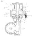
- FIG. 1 is a perspective view showing an electric power steering apparatus according to Embodiment 1 of the present invention, and shows a configuration of a general column-type electric power steering apparatus.
- an electric power steering apparatus 100 includes a steering wheel 1 for steering a vehicle, a steering shaft 2 connected to the steering wheel 1, a steering column 3 that rotatably houses the steering shaft 2, and a steering wheel 1.
- a torque sensor 4 for detecting the steering torque of the vehicle, a vehicle speed sensor 5 for detecting the traveling speed of the vehicle, an electric motor 11 for applying a steering assist force to the handle 1, and signals of the torque sensor 4 and the vehicle speed sensor 5 are input.
- a control device 12 for controlling the driving of the electric motor 11 corresponding to the steering torque and the running condition of the vehicle, a transmission mechanism 13 connected to the steering column 3 and transmitting the rotation of the electric motor 11 to the steering shaft 2, and the electric motor 11.
- a power supply unit 14 is provided for supplying a current for driving.
- FIG. 2 is a cross-sectional view of the electric power steering apparatus according to Embodiment 1 of the present invention.
- the electric motor 11 is configured by a three-phase brushless electric motor, and includes a stator 17 having a rotor 17, an armature winding 18 composed of a U phase, a V phase, and a W phase, and an outer periphery of the stator 19.
- An electric motor frame 20 is provided to cover the part.
- the control device 12 includes a control circuit 22, a power unit 23 for driving the electric motor 11, a frame 24 in which a plurality of conductive plates are insert-molded, the torque sensor 4, the vehicle speed sensor 5. And a connector 27 that connects the power supply unit 14, a housing 25 that surrounds the control circuit 22, and a metal plate 21 that is in contact with the housing 25 and has a high thermal conductivity.
- the motor frame 20, the housing 25, and the plate 21 are integrally formed on the same axis as the output shaft 28 of the motor 11, and at least of the plate 21 and the housing 25 arranged on the front transmission mechanism 13 side of the motor 11.
- One is made of magnesium or a magnesium alloy.
- the electric power steering apparatus 100 when an ignition switch (not shown) of the vehicle is turned on, power is supplied to the control apparatus 12 from the power supply unit 14 via the connector 27. Is done. Information signals from the torque sensor 4 and the vehicle speed sensor 5 are input to a microcomputer (not shown) mounted on the control circuit 22 via the connector 27.
- the microcomputer calculates a current value corresponding to the steering assist torque and supplies a motor drive current corresponding to the current value calculated by the power unit 23 to the motor 11.
- the electric motor 11 outputs a required amount of auxiliary torque in the required rotation direction in accordance with the supplied electric motor driving current.
- the electric power steering apparatus includes an electric motor 11 that assists a vehicle steering operation, an electric motor frame 20 that incorporates the electric motor 11, and a housing 25 that includes a control circuit 22 that controls the driving of the electric motor 11.
- the electric power steering apparatus 100 that includes a plate 21 that abuts against the housing 25 and applies a steering assist force by the transmission mechanism 13 that transmits the rotation of the electric motor 11 to the steering shaft 2, the output shaft 28 of the electric motor 11
- the electric motor frame 20, the housing 25, and the plate 21 are integrally formed on the same axis, and at least one of the plate 21 and the housing 25 disposed on the front transmission mechanism 13 side of the electric motor 11 is formed of magnesium or a magnesium alloy. ing.
- the vibration damping capability of the magnesium alloy is about twice or more compared to the iron-based alloy and the aluminum alloy among the conventional housing materials that ensure heat dissipation. Since it is large, it is difficult to be transmitted to the electric motor side, so that the stress of the electric motor frame is relieved, and the vibration resistance can be improved while ensuring the heat dissipation.
- At least one of the plate 21 and the housing 25 is made of magnesium or a magnesium alloy.
- the longitudinal elastic modulus is about 0.6 times smaller and the 0.2% resistance is almost the same. It is higher than aluminum alloy and resistant to deformation, cracking, etc. for resin materials, so it is lightweight and secures heat dissipation when stepping on falling stones, foreign object collisions and falling objects when traveling. Deformation resistance or breaking strength can be improved.
- the specific gravity of magnesium alloy is about 0.7 times and about 0.2 times lighter than aluminum alloy and iron-based alloy, respectively, and is almost equivalent to resin material. Although it is twice, it is about 1.3 times and about 60 times larger than iron-based alloys and resin materials, respectively, so that it is possible to reduce the weight while ensuring the heat dissipation of the device.
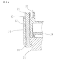
- FIG. FIG. 3 is an enlarged partial cross-sectional view of the thread portion of the electric power steering device according to Embodiment 2 of the present invention, and shows the configuration of the electric motor 11 and the control device 12.
- the three parts of the electric motor frame 20, the housing 25, and the plate 21 are fixed with screws 30.
- At least one of the plate 21 and the housing 25 is formed of magnesium or a magnesium alloy, and at least one portion formed of magnesium or the magnesium alloy is provided with a through hole 32 for the screw 30.
- a female screw portion 31 is formed at a portion formed of a metal material other than magnesium or magnesium alloy, and the screw 30 is inserted into the through hole 32 and screwed into the female screw portion 31 to generate a screw axial force. Provides a binding force to hold and fix.
- Other configurations are the same as those in the first embodiment.
- the tensile strength of the magnesium alloy is about 0.2 times and about 0.5 times smaller than those of the aluminum alloy and the iron-based alloy, respectively.
- the screw shaft force is reduced and the fastening failure is less likely to occur due to the crushing of the female screw, the strength and vibration resistance of the apparatus are improved, and the same effect as in the first embodiment can be obtained.
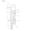
- FIG. 4a is an enlarged partial cross-sectional view of a thread portion of an electric power steering apparatus according to Embodiment 3 of the present invention.
- the female screw portion 31 is formed in a portion formed of a metal material other than magnesium or a magnesium alloy.
- a female thread portion 31 is formed in the burring portion 33 applied in this manner.
- Other configurations are the same as those of the second embodiment. Even with such a configuration, the same effect as in the second embodiment can be obtained.
- FIG. 4b is an enlarged partial cross-sectional view of the thread portion of the electric power steering apparatus according to Embodiment 4 of the present invention.
- the female screw portion 31 is formed in the burring portion 33.
- the nut 34 having the female screw portion 31 is used in the fourth embodiment shown in FIG. 4B.
- Other configurations are the same as those of the second embodiment. Even with such a configuration, the same effect as in the second embodiment can be obtained.
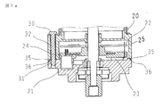
- FIG. 5 is a cross-sectional view of an electric power steering device according to Embodiment 5 of the present invention, which is configured as a general electric power steering device, and shows the configuration of the electric motor and the control device.
- a housing 25 and a plate 21 are disposed on the opposite side of the output shaft 28 of the electric motor 11, and at least one of the electric motor frame 20, the housing 25 and the plate 21 is formed of magnesium or a magnesium alloy.
- Other configurations are the same as those of the second embodiment. Even with such a configuration, the same effect as in the second embodiment can be obtained.
- FIG. 6a is an enlarged partial cross-sectional view of a thread portion of an electric power steering apparatus according to Embodiment 6 of the present invention.
- the motor frame 20 is formed of magnesium or a magnesium alloy
- the sixth embodiment as shown in FIG. It is made to be done.
- the electric power steering apparatus 100 configured as described above can efficiently radiate the heat generated by the electric motor 11 to the outside, the heat dissipation of the electric power steering apparatus is improved and vibration is transmitted from the transmission mechanism 13 to the electric motor 11. At this time, the vibration from the transmission mechanism 13 side is attenuated by the motor frame 20 and the vibration transmitted to the control device 12 is reduced, so that the solder strength of the mounted components on the control circuit 22 in the control device 12 and the contacts of the connector 27 are reduced. The contact reliability of the part is improved.
- FIG. 6b is an enlarged partial cross-sectional view of a thread portion of an electric power steering apparatus according to Embodiment 7 of the present invention.
- the female screw 31 is installed on the plate 21, but in the seventh embodiment, a nut 34 is used as shown in FIG. 6b.
- Other configurations are the same as those of the fifth embodiment. Even with such a configuration, the same effect as in the sixth embodiment can be obtained.
- FIG. 7a is a cross-sectional view of an electric power steering apparatus according to Embodiment 8 of the present invention, which is configured as a general electric power steering apparatus, and shows the configuration of an electric motor and a control apparatus.
- a housing 25 made of magnesium or a magnesium alloy is provided with an annular rib 35 over substantially the entire circumference, and a substantially annular notch 36 is formed in the plate 21 in contact with the rib 35. These are fixed to each other so as to face each other. Other configurations are the same as those of the second embodiment.
- Magnesium alloy is easier to form a thin shape because it has better die casting than aluminum alloy. For this reason, secondary processing becomes unnecessary and the cost can be reduced. Further, since it is possible to prevent the entry of foreign matters from the outside, it is not necessary to use an adhesive or the like, so that the assembling property can be improved and the cost can be reduced. Also with this configuration, the same effect as in the second embodiment can be obtained.
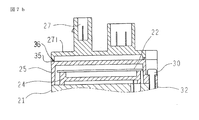
- FIG. 7b is a cross-sectional view of an electric power steering apparatus according to Embodiment 9 of the present invention, which is configured as a general electric power steering apparatus, and shows the configuration of the electric motor and the control apparatus.
- the housing 25 formed of magnesium or a magnesium alloy is provided with an annular rib 35 over substantially the entire circumference, and the connector support member 271 that contacts the housing 25 has an approximately annular notch. 36 are formed, these are opposed to each other, and both portions are closely attached and fixed.
- Other configurations are the same as those of the fifth embodiment. Even with such a configuration, the same effect as in the fifth and sixth embodiments can be obtained.
- the housing 25 is formed of magnesium or a magnesium alloy, surrounds the outer periphery of the built-in control circuit 22, and is substantially the same as one or both of the motor frame 20 and the plate 21. It is designed to be closely attached and fixed over the entire circumference. Other configurations are the same as those of the second embodiment.
- the housing 25 is fixed in close contact with one or both of the motor frame 20 and the plate 21 over substantially the entire circumference, so that the strength, damping effect, and heat dissipation of the electric power steering device are improved.
- the inner volume of the housing 25 can be increased and the control circuit 22 can be enlarged. Therefore, the mounting area of the electronic component can be increased while reducing the weight.
- the housing 25 is formed by die casting, a thin shape can be formed as compared with aluminum or an aluminum alloy, so that the number of processing steps can be reduced, thereby reducing the cost. Even with such a configuration, the same effect as in the second embodiment can be obtained.
- Embodiment 11 FIG.
- the above-described screw 30 is formed of a metal material having substantially the same coefficient of thermal expansion as that of the portion where the through hole 32 is provided.
- Other configurations are the same as those of the second embodiment.
- the thermal linear expansion coefficient of the iron-based alloy is about 1/3 times and about 1/2 times that of the magnesium alloy and aluminum alloy, respectively. Since magnesium alloy and aluminum alloy are larger than magnesium alloy, if magnesium, magnesium alloy, aluminum or aluminum alloy is used for the metal material of screw 30, screw axial force decreases at low temperature, and plasticity of magnesium alloy parts at high temperature Generation of deformation, destruction, etc. can be prevented. Also with this configuration, the same effect as in the second embodiment can be obtained.
- the embodiments can be freely combined, and the embodiments can be appropriately modified or omitted.
- the present invention can be used in the field of electric power steering devices, and in the field of vehicles such as automobiles using the electric power steering device.
Abstract
Description
電動機を内蔵する電動機フレームと、前記電動機の回転を制御する制御回路を内蔵したハウジングと、前記ハウジングに当接するプレートとを備え、前記電動機の回転を伝達機構を介して車両の操舵軸に伝達する電動パワーステアリング装置であって、
前記電動機フレームと前記ハウジングと前記プレートとは、前記電動機の出力軸と同軸上に一体に構成され、
前記電動機フレームと前記ハウジングと前記プレートとのうちの少なくとも一つは、マグネシウム又はマグネシウム合金で形成されている、
ことを特徴とする。 The electric power steering device according to the present invention is:
An electric motor frame including an electric motor, a housing including a control circuit for controlling the rotation of the electric motor, and a plate that contacts the housing, and transmits the rotation of the electric motor to a steering shaft of the vehicle via a transmission mechanism. An electric power steering device,
The motor frame, the housing, and the plate are integrally formed coaxially with the output shaft of the motor,
At least one of the motor frame, the housing, and the plate is formed of magnesium or a magnesium alloy,
It is characterized by that.
図1は、この発明の実施の形態1による電動パワーステアリング装置を示す斜視図であって、一般的なコラム型電動パワーステアリング装置の構成を示している。図1に於いて、この電動パワーステアリング装置100は、車両操舵を行うハンドル1と、前記ハンドル1に連結された操舵軸2と、操舵軸2を回転自在に内装するステアリングコラム3と、ハンドル1の操舵トルクを検出するトルクセンサ4と、車両の走行速度を検出する車速センサ5と、ハンドル1に対して操舵補助力を付与する電動機11と、トルクセンサ4と車速センサ5の信号を入力し、操舵トルクや車両の走行条件に対応して前記電動機11の駆動を制御する制御装置12と、ステアリングコラム3と連結され、電動機11の回転を操舵軸2に伝達する伝達機構13と、電動機11を駆動するための電流を供給する電源部14を備えている。
FIG. 1 is a perspective view showing an electric power steering apparatus according to
電動機11は、図2に示すように、3相ブラシレス電動機で構成され、回転子17とU相、V相、W相からなる電機子巻線18を有する固定子19と、固定子19の外周部を覆う電動機フレーム20を備えている。 FIG. 2 is a cross-sectional view of the electric power steering apparatus according to
As shown in FIG. 2, the
図3は、この発明の実施の形態2による電動パワーステアリング装置のネジ部の部分断面拡大図であって、電動機11と制御装置12の構成を示すものである。図3に於いて、電動機フレーム20とハウジング25とプレート21と、の3つの部位はネジ30で固定されている。そして、プレート21とハウジング25とのうちの少なくとも一つは、マグネシウム又はマグネシウム合金で形成され、且つマグネシウム又はマグネシウム合金で形成された少なくとも一つの部位は、ネジ30用の貫通穴32が設けられている。マグネシウム又はマグネシウム合金以外の金属材料で形成された部位に雌ネジ部31が形成され、ネジ30を貫通穴32に挿通して雌ネジ部31に螺合し、ネジ軸力を発生させることで狭持固定する結合力を与えている。その他の構成は実施の形態1と同様である。
FIG. 3 is an enlarged partial cross-sectional view of the thread portion of the electric power steering device according to
図4aは、この発明の実施の形態3による電動パワーステアリング装置のネジ部の部分断面拡大図である。前述の実施の形態2に於いては、雌ネジ部31をマグネシウム又はマグネシウム合金以外の金属材料で形成された部位に形成したが、図4aに示す実施の形態3では、電動機フレーム20をバーリング加工して施されたバーリング部33に雌ネジ部31を形成している。その他の構成は実施の形態2と同様である。このような構成によっても実施の形態2と同様の効果を得ることができる。
4a is an enlarged partial cross-sectional view of a thread portion of an electric power steering apparatus according to
図4bは、この発明の実施の形態4による電動パワーステアリング装置のネジ部の部分断面拡大図である。実施の形態3に於いては、バーリング部33に雌ネジ部31を形成したが、図4bに示す実施の形態4では、雌ネジ部31が形成されたナット34を用いたものである。その他の構成は実施の形態2と同様である。このような構成によっても実施の形態2と同様の効果を得ることができる。
FIG. 4b is an enlarged partial cross-sectional view of the thread portion of the electric power steering apparatus according to
図5は、この発明の実施の形態5による電動パワーステアリング装置の断面図であって、一般的な電動パワーステアリング装置として構成され、電動機と制御装置の構成を示すものである。図5に於いて、電動機11の出力軸28と反対側にハウジング25とプレート21が配置され、少なくとも電動機フレーム20とハウジング25とプレート21とのうちの少なくとも一つはマグネシウム又はマグネシウム合金で形成されている。その他の構成は実施の形態2と同様である。このような構成によっても実施の形態2と同様の効果を得ることができる。
FIG. 5 is a cross-sectional view of an electric power steering device according to
図6aは、この発明の実施の形態6による電動パワーステアリング装置のネジ部の部分断面拡大図である。前述の図5に示す実施の形態5の構成で、電動機フレーム20がマグネシウム又はマグネシウム合金で形成されている場合に、実施の形態6では図6aに示すように、プレート21に雌ネジ31が設置されるようにしたものである。
FIG. 6a is an enlarged partial cross-sectional view of a thread portion of an electric power steering apparatus according to
図6bは、この発明の実施の形態7による電動パワーステアリング装置のネジ部の部分断面拡大図である。前述の実施の形態6に於いては、プレート21に雌ネジ31を設置するようにしたが、実施の形態7では図6bに示すように、ナット34を使用するようにしたものである。その他の構成は実施の形態5と同様である。このような構成によっても実施の形態6と同様の効果を得ることができる。
6b is an enlarged partial cross-sectional view of a thread portion of an electric power steering apparatus according to
図7aは、この発明の実施の形態8による電動パワーステアリング装置の断面図であって、一般的な電動パワーステアリング装置として構成され、電動機と制御装置の構成を示すものである。図7aに於いて、マグネシウム又はマグネシウム合金で形成されたハウジング25には、ほぼ全周にわたって環状のリブ35が設けられ、そのリブ35と当接するプレート21にはほぼ環状の切欠き部36が形成され、これ等が互いに対向し密着して固定されている。その他の構成は実施の形態2と同様である。 Embodiment 8 FIG.
FIG. 7a is a cross-sectional view of an electric power steering apparatus according to Embodiment 8 of the present invention, which is configured as a general electric power steering apparatus, and shows the configuration of an electric motor and a control apparatus. In FIG. 7a, a
図7bは、この発明の実施の形態9による電動パワーステアリング装置の断面図であって、一般的な電動パワーステアリング装置として構成され、電動機と制御装置の構成を示すものである。図7bに於いて、マグネシウム又はマグネシウム合金で形成されたハウジング25には、ほぼ全周にわたって環状のリブ35が設けられ、そのハウジング25と当接するコネクタ支持部材271には、ほぼ環状の切欠き部36が形成され、これ等が互いに対向し、両部位が密着して固定されている。その他の構成は実施の形態5と同様である。このような構成によっても実施の形態5及び実施の形態6と同様の効果を得ることができる。 Embodiment 9 FIG.
FIG. 7b is a cross-sectional view of an electric power steering apparatus according to Embodiment 9 of the present invention, which is configured as a general electric power steering apparatus, and shows the configuration of the electric motor and the control apparatus. In FIG. 7 b, the
この発明の実施の形態10による電動パワーステアリング装置は、前述のハウジング25をマグネシウム又はマグネシウム合金により形成し、内蔵された制御回路22の外周を囲み、電動機フレーム20とプレート21の一方若しくは両方と略全周にわたって密着して固定されるようにしたものである。その他の構成は実施の形態2と同様である。 Embodiment 10 FIG.
In the electric power steering apparatus according to Embodiment 10 of the present invention, the
この発明の実施の形態11による電動パワーステアリング装置は、前述のネジ30を、貫通穴32が設けられた部位とほぼ同一の熱線膨張係数を有した金属材料で形成したものである。その他の構成は実施の形態2と同様である。
In the electric power steering apparatus according to
5 車速センサ、11 電動機、12 制御装置、13 伝達機構、
14 電源部、17 回転子、18 電機子巻き線、19 固定子、
20 電動機フレーム、21 プレート、22 制御回路、
23 パワー部、24 フレーム、25 ハウジング、27 コネクタ、
271 コネクタ支持部材、28出力軸、30 ネジ、31 雌ネジ部、
32 貫通穴、33 バーリング部、34 ナット、35 リブ、
36 切欠き部、100 電動パワーステアリング装置。 1 steering wheel, 2 steering shaft, 3 steering column, 4 torque sensor,
5 Vehicle speed sensor, 11 Electric motor, 12 Control device, 13 Transmission mechanism,
14 power supply unit, 17 rotor, 18 armature winding, 19 stator,
20 motor frame, 21 plate, 22 control circuit,
23 power section, 24 frame, 25 housing, 27 connector,
271 Connector support member, 28 output shaft, 30 screw, 31 female screw part,
32 through hole, 33 burring part, 34 nut, 35 rib,
36 Notch, 100 Electric power steering device.
Claims (7)
- 電動機を内蔵する電動機フレームと、前記電動機の回転を制御する制御回路を内蔵したハウジングと、前記ハウジングに当接するプレートとを備え、前記電動機の回転を伝達機構を介して車両の操舵軸に伝達する電動パワーステアリング装置であって、
前記電動機フレームと前記ハウジングと前記プレートとは、前記電動機の出力軸と同軸上に一体に構成され、
前記電動機フレームと前記ハウジングと前記プレートとのうちの少なくとも一つは、マグネシウム又はマグネシウム合金で形成されている、
ことを特徴とする電動パワーステアリング装置。 An electric motor frame including an electric motor, a housing including a control circuit for controlling the rotation of the electric motor, and a plate that contacts the housing, and transmits the rotation of the electric motor to a steering shaft of the vehicle via a transmission mechanism. An electric power steering device,
The motor frame, the housing, and the plate are integrally formed coaxially with the output shaft of the motor,
At least one of the motor frame, the housing, and the plate is formed of magnesium or a magnesium alloy,
An electric power steering device. - 前記電動機フレームと前記ハウジングと前記プレートとは、ネジで一体に固定され、
前記電動機フレームと前記ハウジングと前記プレートとのうちの、マグネシウム又はマグネシウム合金で形成された少なくとも一つは、前記ネジを貫通させる貫通穴が形成されている、
ことを特徴とする請求項1記載の電動パワーステアリング装置。 The motor frame, the housing, and the plate are integrally fixed with screws,
Of the electric motor frame, the housing, and the plate, at least one formed of magnesium or a magnesium alloy is formed with a through hole through which the screw passes.
The electric power steering apparatus according to claim 1. - 前記ハウジングと前記プレートとは、前記電動機と前記伝達機構との間に配置され、
前記ハウジングと前記プレートとのうちの少なくとも一つは、マグネシウム、又はマグネシウム合金で形成されている、
ことを特徴とする請求項2記載の電動パワーステアリング装置。 The housing and the plate are disposed between the electric motor and the transmission mechanism,
At least one of the housing and the plate is made of magnesium or a magnesium alloy,
The electric power steering apparatus according to claim 2. - 前記ハウジングと前記プレートとは、前記電動機の反伝達機構側に配置され、
前記電動機フレームと前記ハウジングと前記プレートとのうちの少なくとも一つは、マグネシウム、又はマグネシウム合金で形成されている、
ことを特徴とする請求項2記載の電動パワーステアリング装置。 The housing and the plate are disposed on the counter-transmission mechanism side of the electric motor,
At least one of the motor frame, the housing, and the plate is formed of magnesium or a magnesium alloy,
The electric power steering apparatus according to claim 2. - 前記電動機フレームと前記ハウジングと前記プレートとのうちの、マグネシウム又はマグネシウム合金で形成された少なくとも一つは、ほぼ全周にわたって形成された環状のリブを備え、
前記少なくとも一つに当接する他の一つは、ほぼ環状形成された切り欠き部を備え、
前記リブと前記切り欠き部が互いに対向して密着して固定されている、
ことを特徴とする請求項2記載の電動パワーステアリング装置。 Of the electric motor frame, the housing, and the plate, at least one formed of magnesium or a magnesium alloy includes an annular rib formed over substantially the entire circumference,
The other one that abuts the at least one has a substantially annular notch,
The rib and the notch are fixed in close contact with each other.
The electric power steering apparatus according to claim 2. - 前記ハウジングは、マグネシウム又はマグネシウム合金で形成されると共に、内蔵された前記制御回路の外周を囲み、
前記電動機フレームと前記プレートとのうちの一方又は両方と、ほぼ全周にわたって密着して固定されている、
ことを特徴とする請求項2記載の電動パワーステアリング装置。 The housing is formed of magnesium or a magnesium alloy and surrounds an outer periphery of the built-in control circuit,
One or both of the motor frame and the plate are fixed in close contact with substantially the entire circumference,
The electric power steering apparatus according to claim 2. - 前記ネジは、前記貫通穴が形成されている前記少なくとも一つとほぼ同一の線膨張係数を有する金属材料で形成されている、
ことを特徴とする請求項2記載の電動パワーステアリング装置。
The screw is formed of a metal material having a linear expansion coefficient substantially the same as the at least one in which the through hole is formed.
The electric power steering apparatus according to claim 2.
Priority Applications (4)
| Application Number | Priority Date | Filing Date | Title |
|---|---|---|---|
| CN201380077877.4A CN105339238B (en) | 2013-07-03 | 2013-09-19 | Electric power steering device |
| US14/768,234 US9878734B2 (en) | 2013-07-03 | 2013-09-19 | Electric power steering apparatus |
| JP2015525006A JPWO2015001684A1 (en) | 2013-07-03 | 2013-09-19 | Electric power steering device |
| EP13888588.4A EP3018036B1 (en) | 2013-07-03 | 2013-09-19 | Electric power steering apparatus |
Applications Claiming Priority (2)
| Application Number | Priority Date | Filing Date | Title |
|---|---|---|---|
| JP2013139515 | 2013-07-03 | ||
| JP2013-139515 | 2013-07-03 |
Publications (1)
| Publication Number | Publication Date |
|---|---|
| WO2015001684A1 true WO2015001684A1 (en) | 2015-01-08 |
Family
ID=52143297
Family Applications (1)
| Application Number | Title | Priority Date | Filing Date |
|---|---|---|---|
| PCT/JP2013/075285 WO2015001684A1 (en) | 2013-07-03 | 2013-09-19 | Electric power steering apparatus |
Country Status (5)
| Country | Link |
|---|---|
| US (1) | US9878734B2 (en) |
| EP (1) | EP3018036B1 (en) |
| JP (1) | JPWO2015001684A1 (en) |
| CN (1) | CN105339238B (en) |
| WO (1) | WO2015001684A1 (en) |
Cited By (1)
| Publication number | Priority date | Publication date | Assignee | Title |
|---|---|---|---|---|
| CN105966452A (en) * | 2015-03-10 | 2016-09-28 | 株式会社昭和 | Housing structure and power steering apparatus |
Citations (11)
| Publication number | Priority date | Publication date | Assignee | Title |
|---|---|---|---|---|
| JPH10243605A (en) * | 1996-12-27 | 1998-09-11 | Sankyo Seiki Mfg Co Ltd | Fixed shaft motor |
| JP2001512957A (en) * | 1997-08-06 | 2001-08-28 | シャーフロ パンプ マニュファクチュアリング カンパニー | Electric machine and stator used for it |
| JP3774624B2 (en) | 2000-10-18 | 2006-05-17 | 三菱電機株式会社 | Electric power steering device |
| JP2007335735A (en) * | 2006-06-16 | 2007-12-27 | Toyota Motor Corp | Semiconductor device |
| JP2008285142A (en) * | 2007-04-16 | 2008-11-27 | Jtekt Corp | Vehicle steering device |
| WO2009101794A1 (en) * | 2008-02-12 | 2009-08-20 | Jtekt Corporation | Vehicle steering device |
| JP2009186173A (en) * | 2008-02-07 | 2009-08-20 | General Electric Co <Ge> | Gasification feed injector and method of modifying cast surface thereof |
| JP2009254141A (en) * | 2008-04-07 | 2009-10-29 | Mitsubishi Electric Corp | Motor for controller integrated electric power steering apparatus and electric power steering apparatus |
| JP2010089739A (en) * | 2008-10-10 | 2010-04-22 | Nsk Ltd | Electric power steering device |
| JP2012143036A (en) | 2010-12-28 | 2012-07-26 | Denso Corp | Driving device and electric power steering device using the same |
| JP2012197051A (en) * | 2011-03-23 | 2012-10-18 | Hitachi Automotive Systems Steering Ltd | Electric power steering device |
Family Cites Families (11)
| Publication number | Priority date | Publication date | Assignee | Title |
|---|---|---|---|---|
| US7886865B2 (en) | 2006-04-11 | 2011-02-15 | Nsk Ltd. | Electric power steering apparatus |
| KR101019341B1 (en) | 2006-04-11 | 2011-03-07 | 닛본 세이고 가부시끼가이샤 | Electric power steering device and method of assembling the same |
| CN100470064C (en) * | 2006-06-29 | 2009-03-18 | 重庆隆鑫工业(集团)有限公司 | Thread fixing structure of thermal-state magnesium alloy component |
| JP2008037131A (en) | 2006-08-01 | 2008-02-21 | Nsk Ltd | Electric power steering device |
| WO2008132931A1 (en) | 2007-04-19 | 2008-11-06 | Nsk Ltd. | Electric power steering device |
| JP2009286173A (en) * | 2008-05-27 | 2009-12-10 | Nsk Ltd | Electric power steering device |
| CN102123902A (en) | 2009-10-30 | 2011-07-13 | 日本精工株式会社 | Electric power steering device |
| JP5039171B2 (en) * | 2010-05-11 | 2012-10-03 | 三菱電機株式会社 | Electric drive device and electric power steering device equipped with the electric drive device |
| WO2012012389A1 (en) * | 2010-07-19 | 2012-01-26 | Ems Engineered Materials Solutions, Llc | A metallic composite material |
| WO2012073412A1 (en) | 2010-12-02 | 2012-06-07 | 日本精工株式会社 | Electric power steering device |
| WO2012077264A1 (en) | 2010-12-07 | 2012-06-14 | 日本精工株式会社 | Electric power steering device |
-
2013
- 2013-09-19 WO PCT/JP2013/075285 patent/WO2015001684A1/en active Application Filing
- 2013-09-19 US US14/768,234 patent/US9878734B2/en active Active
- 2013-09-19 JP JP2015525006A patent/JPWO2015001684A1/en active Pending
- 2013-09-19 EP EP13888588.4A patent/EP3018036B1/en active Active
- 2013-09-19 CN CN201380077877.4A patent/CN105339238B/en active Active
Patent Citations (11)
| Publication number | Priority date | Publication date | Assignee | Title |
|---|---|---|---|---|
| JPH10243605A (en) * | 1996-12-27 | 1998-09-11 | Sankyo Seiki Mfg Co Ltd | Fixed shaft motor |
| JP2001512957A (en) * | 1997-08-06 | 2001-08-28 | シャーフロ パンプ マニュファクチュアリング カンパニー | Electric machine and stator used for it |
| JP3774624B2 (en) | 2000-10-18 | 2006-05-17 | 三菱電機株式会社 | Electric power steering device |
| JP2007335735A (en) * | 2006-06-16 | 2007-12-27 | Toyota Motor Corp | Semiconductor device |
| JP2008285142A (en) * | 2007-04-16 | 2008-11-27 | Jtekt Corp | Vehicle steering device |
| JP2009186173A (en) * | 2008-02-07 | 2009-08-20 | General Electric Co <Ge> | Gasification feed injector and method of modifying cast surface thereof |
| WO2009101794A1 (en) * | 2008-02-12 | 2009-08-20 | Jtekt Corporation | Vehicle steering device |
| JP2009254141A (en) * | 2008-04-07 | 2009-10-29 | Mitsubishi Electric Corp | Motor for controller integrated electric power steering apparatus and electric power steering apparatus |
| JP2010089739A (en) * | 2008-10-10 | 2010-04-22 | Nsk Ltd | Electric power steering device |
| JP2012143036A (en) | 2010-12-28 | 2012-07-26 | Denso Corp | Driving device and electric power steering device using the same |
| JP2012197051A (en) * | 2011-03-23 | 2012-10-18 | Hitachi Automotive Systems Steering Ltd | Electric power steering device |
Cited By (3)
| Publication number | Priority date | Publication date | Assignee | Title |
|---|---|---|---|---|
| CN105966452A (en) * | 2015-03-10 | 2016-09-28 | 株式会社昭和 | Housing structure and power steering apparatus |
| US9926002B2 (en) | 2015-03-10 | 2018-03-27 | Showa Corporation | Housing structure and power steering apparatus |
| CN105966452B (en) * | 2015-03-10 | 2018-11-06 | 株式会社昭和 | Shell mechanism and power steering gear |
Also Published As
| Publication number | Publication date |
|---|---|
| CN105339238A (en) | 2016-02-17 |
| EP3018036B1 (en) | 2019-06-26 |
| EP3018036A4 (en) | 2017-03-01 |
| US9878734B2 (en) | 2018-01-30 |
| CN105339238B (en) | 2018-07-24 |
| EP3018036A1 (en) | 2016-05-11 |
| JPWO2015001684A1 (en) | 2017-02-23 |
| US20150375775A1 (en) | 2015-12-31 |
Similar Documents
| Publication | Publication Date | Title |
|---|---|---|
| JP5067159B2 (en) | Electric power steering device | |
| KR101900134B1 (en) | Electromotive drive and electric power steering device | |
| US11870326B2 (en) | Electric drive apparatus, and electric power steering apparatus | |
| WO2016125700A1 (en) | Electric driving device and electric power steering device | |
| EP2805872B1 (en) | Integrated electric power steering apparatus | |
| JP5310546B2 (en) | Electric power steering device | |
| JP5298459B2 (en) | Electric power steering device | |
| JP2009078690A (en) | Electrical power steering device | |
| EP1842762A1 (en) | Electric power steering device | |
| WO2015001684A1 (en) | Electric power steering apparatus | |
| JP5229612B2 (en) | Electric power steering device | |
| JP5787000B2 (en) | Electric power steering device | |
| JP4952666B2 (en) | Electric power steering device | |
| JP6486250B2 (en) | Electric drive | |
| JP2008179248A (en) | Electric power steering device | |
| JP2010036649A (en) | Electric power steering device | |
| JP5566355B2 (en) | Electric power steering device | |
| JP2010012850A (en) | Electric power steering device | |
| JP2016144381A (en) | Electrically-driven driving device and electric power steering device | |
| JP2009274489A (en) | Vehicular steering device | |
| JP5773019B2 (en) | Electric power steering device | |
| JP2008285005A (en) | Electric power steering device | |
| JP2009035190A (en) | Electric power steering device | |
| JP2010006310A (en) | Electric power steering device | |
| JP2017007574A (en) | Electric power steering device |
Legal Events
| Date | Code | Title | Description |
|---|---|---|---|
| WWE | Wipo information: entry into national phase |
Ref document number: 201380077877.4 Country of ref document: CN |
|
| 121 | Ep: the epo has been informed by wipo that ep was designated in this application |
Ref document number: 13888588 Country of ref document: EP Kind code of ref document: A1 |
|
| ENP | Entry into the national phase |
Ref document number: 2015525006 Country of ref document: JP Kind code of ref document: A |
|
| WWE | Wipo information: entry into national phase |
Ref document number: 14768234 Country of ref document: US |
|
| WWE | Wipo information: entry into national phase |
Ref document number: 2013888588 Country of ref document: EP |
|
| NENP | Non-entry into the national phase |
Ref country code: DE |