JP5634610B2 - Electric drive - Google Patents
Electric drive Download PDFInfo
- Publication number
- JP5634610B2 JP5634610B2 JP2013533454A JP2013533454A JP5634610B2 JP 5634610 B2 JP5634610 B2 JP 5634610B2 JP 2013533454 A JP2013533454 A JP 2013533454A JP 2013533454 A JP2013533454 A JP 2013533454A JP 5634610 B2 JP5634610 B2 JP 5634610B2
- Authority
- JP
- Japan
- Prior art keywords
- motor
- terminal
- drive device
- electric
- electric drive
- Prior art date
- Legal status (The legal status is an assumption and is not a legal conclusion. Google has not performed a legal analysis and makes no representation as to the accuracy of the status listed.)
- Expired - Fee Related
Links
- 239000011347 resin Substances 0.000 claims description 32
- 229920005989 resin Polymers 0.000 claims description 32
- 239000004065 semiconductor Substances 0.000 claims description 29
- 229910000881 Cu alloy Inorganic materials 0.000 claims description 12
- 238000004804 winding Methods 0.000 claims description 8
- 238000007789 sealing Methods 0.000 claims description 4
- 238000003780 insertion Methods 0.000 description 29
- 230000037431 insertion Effects 0.000 description 29
- 239000003990 capacitor Substances 0.000 description 19
- 239000000463 material Substances 0.000 description 15
- 238000003466 welding Methods 0.000 description 14
- 238000005304 joining Methods 0.000 description 13
- 230000009467 reduction Effects 0.000 description 10
- 238000009413 insulation Methods 0.000 description 7
- 238000000465 moulding Methods 0.000 description 7
- 238000003825 pressing Methods 0.000 description 7
- 239000000853 adhesive Substances 0.000 description 6
- 230000001070 adhesive effect Effects 0.000 description 6
- 238000013459 approach Methods 0.000 description 6
- 239000000919 ceramic Substances 0.000 description 6
- 238000007747 plating Methods 0.000 description 6
- RYGMFSIKBFXOCR-UHFFFAOYSA-N Copper Chemical compound [Cu] RYGMFSIKBFXOCR-UHFFFAOYSA-N 0.000 description 5
- 238000005452 bending Methods 0.000 description 5
- 229910052802 copper Inorganic materials 0.000 description 5
- 239000010949 copper Substances 0.000 description 5
- 230000008878 coupling Effects 0.000 description 5
- 238000010168 coupling process Methods 0.000 description 5
- 238000005859 coupling reaction Methods 0.000 description 5
- 238000006073 displacement reaction Methods 0.000 description 5
- 238000001514 detection method Methods 0.000 description 4
- 230000006866 deterioration Effects 0.000 description 4
- 239000004519 grease Substances 0.000 description 4
- 238000012856 packing Methods 0.000 description 4
- 239000003638 chemical reducing agent Substances 0.000 description 3
- 230000017525 heat dissipation Effects 0.000 description 3
- 239000007788 liquid Substances 0.000 description 3
- 238000000034 method Methods 0.000 description 3
- 230000008569 process Effects 0.000 description 3
- 230000005855 radiation Effects 0.000 description 3
- 238000012546 transfer Methods 0.000 description 3
- XLYOFNOQVPJJNP-UHFFFAOYSA-N water Substances O XLYOFNOQVPJJNP-UHFFFAOYSA-N 0.000 description 3
- XEEYBQQBJWHFJM-UHFFFAOYSA-N Iron Chemical compound [Fe] XEEYBQQBJWHFJM-UHFFFAOYSA-N 0.000 description 2
- XAGFODPZIPBFFR-UHFFFAOYSA-N aluminium Chemical compound [Al] XAGFODPZIPBFFR-UHFFFAOYSA-N 0.000 description 2
- 229910052782 aluminium Inorganic materials 0.000 description 2
- 230000008859 change Effects 0.000 description 2
- 238000010586 diagram Methods 0.000 description 2
- 239000000428 dust Substances 0.000 description 2
- 230000000694 effects Effects 0.000 description 2
- 238000004092 self-diagnosis Methods 0.000 description 2
- 229910000679 solder Inorganic materials 0.000 description 2
- 238000005476 soldering Methods 0.000 description 2
- 239000004593 Epoxy Substances 0.000 description 1
- 229910052581 Si3N4 Inorganic materials 0.000 description 1
- ATJFFYVFTNAWJD-UHFFFAOYSA-N Tin Chemical compound [Sn] ATJFFYVFTNAWJD-UHFFFAOYSA-N 0.000 description 1
- 230000005856 abnormality Effects 0.000 description 1
- PNEYBMLMFCGWSK-UHFFFAOYSA-N aluminium oxide Inorganic materials [O-2].[O-2].[O-2].[Al+3].[Al+3] PNEYBMLMFCGWSK-UHFFFAOYSA-N 0.000 description 1
- 230000008901 benefit Effects 0.000 description 1
- 239000004020 conductor Substances 0.000 description 1
- PMHQVHHXPFUNSP-UHFFFAOYSA-M copper(1+);methylsulfanylmethane;bromide Chemical compound Br[Cu].CSC PMHQVHHXPFUNSP-UHFFFAOYSA-M 0.000 description 1
- 238000013461 design Methods 0.000 description 1
- 238000004512 die casting Methods 0.000 description 1
- 238000010828 elution Methods 0.000 description 1
- 239000000945 filler Substances 0.000 description 1
- 239000011521 glass Substances 0.000 description 1
- 230000001771 impaired effect Effects 0.000 description 1
- 230000006698 induction Effects 0.000 description 1
- 239000012212 insulator Substances 0.000 description 1
- 229910052742 iron Inorganic materials 0.000 description 1
- JEIPFZHSYJVQDO-UHFFFAOYSA-N iron(III) oxide Inorganic materials O=[Fe]O[Fe]=O JEIPFZHSYJVQDO-UHFFFAOYSA-N 0.000 description 1
- 230000035515 penetration Effects 0.000 description 1
- 230000002093 peripheral effect Effects 0.000 description 1
- 238000012545 processing Methods 0.000 description 1
- 230000002035 prolonged effect Effects 0.000 description 1
- 238000004080 punching Methods 0.000 description 1
- 229910052710 silicon Inorganic materials 0.000 description 1
- 239000010703 silicon Substances 0.000 description 1
- HQVNEWCFYHHQES-UHFFFAOYSA-N silicon nitride Chemical compound N12[Si]34N5[Si]62N3[Si]51N64 HQVNEWCFYHHQES-UHFFFAOYSA-N 0.000 description 1
Images


Classifications
-
- H—ELECTRICITY
- H02—GENERATION; CONVERSION OR DISTRIBUTION OF ELECTRIC POWER
- H02K—DYNAMO-ELECTRIC MACHINES
- H02K11/00—Structural association of dynamo-electric machines with electric components or with devices for shielding, monitoring or protection
- H02K11/30—Structural association with control circuits or drive circuits
- H02K11/38—Control circuits or drive circuits associated with geared commutator motors of the worm-and-wheel type
-
- B—PERFORMING OPERATIONS; TRANSPORTING
- B62—LAND VEHICLES FOR TRAVELLING OTHERWISE THAN ON RAILS
- B62D—MOTOR VEHICLES; TRAILERS
- B62D5/00—Power-assisted or power-driven steering
- B62D5/04—Power-assisted or power-driven steering electrical, e.g. using an electric servo-motor connected to, or forming part of, the steering gear
- B62D5/0403—Power-assisted or power-driven steering electrical, e.g. using an electric servo-motor connected to, or forming part of, the steering gear characterised by constructional features, e.g. common housing for motor and gear box
- B62D5/0406—Power-assisted or power-driven steering electrical, e.g. using an electric servo-motor connected to, or forming part of, the steering gear characterised by constructional features, e.g. common housing for motor and gear box including housing for electronic control unit
-
- H—ELECTRICITY
- H02—GENERATION; CONVERSION OR DISTRIBUTION OF ELECTRIC POWER
- H02K—DYNAMO-ELECTRIC MACHINES
- H02K11/00—Structural association of dynamo-electric machines with electric components or with devices for shielding, monitoring or protection
- H02K11/20—Structural association of dynamo-electric machines with electric components or with devices for shielding, monitoring or protection for measuring, monitoring, testing, protecting or switching
- H02K11/21—Devices for sensing speed or position, or actuated thereby
- H02K11/225—Detecting coils
-
- H—ELECTRICITY
- H01—ELECTRIC ELEMENTS
- H01R—ELECTRICALLY-CONDUCTIVE CONNECTIONS; STRUCTURAL ASSOCIATIONS OF A PLURALITY OF MUTUALLY-INSULATED ELECTRICAL CONNECTING ELEMENTS; COUPLING DEVICES; CURRENT COLLECTORS
- H01R13/00—Details of coupling devices of the kinds covered by groups H01R12/70 or H01R24/00 - H01R33/00
- H01R13/02—Contact members
- H01R13/10—Sockets for co-operation with pins or blades
- H01R13/11—Resilient sockets
- H01R13/112—Resilient sockets forked sockets having two legs
-
- H—ELECTRICITY
- H02—GENERATION; CONVERSION OR DISTRIBUTION OF ELECTRIC POWER
- H02K—DYNAMO-ELECTRIC MACHINES
- H02K3/00—Details of windings
- H02K3/46—Fastening of windings on the stator or rotor structure
- H02K3/52—Fastening salient pole windings or connections thereto
- H02K3/521—Fastening salient pole windings or connections thereto applicable to stators only
- H02K3/522—Fastening salient pole windings or connections thereto applicable to stators only for generally annular cores with salient poles
-
- H—ELECTRICITY
- H02—GENERATION; CONVERSION OR DISTRIBUTION OF ELECTRIC POWER
- H02K—DYNAMO-ELECTRIC MACHINES
- H02K5/00—Casings; Enclosures; Supports
- H02K5/04—Casings or enclosures characterised by the shape, form or construction thereof
- H02K5/22—Auxiliary parts of casings not covered by groups H02K5/06-H02K5/20, e.g. shaped to form connection boxes or terminal boxes
- H02K5/225—Terminal boxes or connection arrangements
Landscapes
- Engineering & Computer Science (AREA)
- Power Engineering (AREA)
- Chemical & Material Sciences (AREA)
- Combustion & Propulsion (AREA)
- Transportation (AREA)
- Mechanical Engineering (AREA)
- Microelectronics & Electronic Packaging (AREA)
- Motor Or Generator Frames (AREA)
- Power Steering Mechanism (AREA)
Description
本発明は、車両のステアリングに対して補助トルクを出力する電動モータとこの電動モータを駆動制御する制御装置を備えた電動式駆動装置であって、例えば電動式パワーステアリング装置に用いられる電動式駆動装置に関するものである。 The present invention is an electric drive device including an electric motor that outputs an auxiliary torque to a vehicle steering and a control device that controls the drive of the electric motor, for example, an electric drive used in an electric power steering device. It relates to the device.
従来、車両のステアリングに対して補助トルクを出力する電動モータと、この電動モータを駆動制御する制御装置を備えており、この制御装置が電動モータに取り付けられた電動式駆動装置が知られている。この種の電動式駆動装置として、例えば、特許文献1に記載の電動式パワーステアリング装置が提案されている。
特許文献1に記載の電動式パワーステアリング装置では、制御装置である制御ユニットが電動モータの回転軸の軸線上に配置されて電動モータに固定されている。この際、電動モ−タの給電部と制御ユニットの接合部は、ハウジング、またはケ−ス、あるいは両方に設けられた開口部を通して、ハウジング内、またはケ−ス内でネジを用いて接合されている。2. Description of the Related Art Conventionally, an electric motor that outputs an auxiliary torque to the steering of a vehicle and a control device that drives and controls the electric motor are provided, and an electric drive device in which the control device is attached to the electric motor is known. . As this type of electric drive device, for example, an electric power steering device described in
In the electric power steering device described in
特許文献1に記載の電動式パワーステアリング装置に用いられる電動式駆動装置では、電動モータの給電部と制御装置の接合部とを電気的に接続するネジが必要になる。また、ネジを用いて接合するためには、ネジの配置スペースおよびネジ締結用ツールの挿入スペースも必要になる。その結果、部品点数および組立工数が増加してコストが高くなるとともに、装置が大型化するという問題点があった。
In the electric drive device used in the electric power steering device described in
また、上記電動式駆動装置において、開口部から、ネジ締結用ツールを用いてネジを接合することで、給電部と接合部は接合されるため、外部からの異物(塵埃、水滴等)が、この接合部位に侵入して、接合部位の絶縁性が確保できなくなったり、接合部位に水滴が付着することで錆が生じて、導電率が低下したりするおそれがあった。そして、この接合部位の絶縁性、防水性を確保するためには、ネジ締結後、さらにカバーを用いて、ネジ締結用ツールの挿入口を塞ぐ必要がある。これにより、部品点数および組立工数が増加してコストがさらに高くなるという問題点があった。 Further, in the above electric drive device, by joining the screw from the opening using a screw fastening tool, the power feeding part and the joint part are joined, so that foreign matter (dust, water droplets, etc.) from the outside is There was a risk that the penetration into the bonded part could not secure the insulating property of the bonded part, or rust was generated by water droplets adhering to the bonded part, resulting in a decrease in conductivity. And in order to ensure the insulation of this joint part and waterproofness, after screw fastening, it is necessary to block the insertion port of the tool for screw fastening further using a cover. As a result, the number of parts and the number of assembling steps are increased, resulting in a further increase in cost.
本発明は、上記のような問題点を解決することを課題とするものであって、電動モータと制御装置とを備えた電動式駆動装置において、部品点数および組立工数を削減した電動式駆動装置を提供することを目的とするものである。 An object of the present invention is to solve the above-described problems, and in an electric drive device including an electric motor and a control device, the electric drive device in which the number of parts and the number of assembly steps are reduced. Is intended to provide.
本発明に係る電動式駆動装置は、電動モータと、前記電動モータの回転軸の軸線上に配置され、前記電動モータを駆動制御する制御装置とを備えた電動式駆動装置であって、前記制御装置は、前記電動モータの電流切り替えを行う半導体スイッチング素子および前記スイッチング素子に電気的に接続される受動素子からなる、前記電動モータを駆動する駆動部と、前記受動素子の各端子がそれぞれ接続される複数の導電板が絶縁性樹脂によりインサート成型されるとともに、前記受動素子が配設されたフレームとを備え、前記電動モータまたは前記制御装置のうち、一方には、他方に向かって前記回転軸の軸線方向と平行に延出する第1の端子を有するとともに、前記第1の端子のうち、他方側端部にスリットが形成され、他方には、前記第1の端子の延出線上に設けられて、前記第1の端子に電気的に接続される第2の端子を有し、前記スリットが前記第2の端子を挟み込むことで、前記第1の端子は前記第2の端子に圧入された状態で固定されるものである。 An electric drive device according to the present invention is an electric drive device comprising: an electric motor; and a control device that is disposed on an axis of a rotation shaft of the electric motor and controls driving of the electric motor. The apparatus includes a semiconductor switching element that switches a current of the electric motor and a passive element that is electrically connected to the switching element, and a drive unit that drives the electric motor and each terminal of the passive element are connected to each other. A plurality of conductive plates insert-molded with an insulating resin and a frame on which the passive element is disposed, and one of the electric motor and the control device has the rotating shaft toward the other. A first terminal extending in parallel with the axial direction of the first terminal, and a slit is formed at the other end of the first terminal, The second terminal is electrically connected to the first terminal, and the slit sandwiches the second terminal so that the first terminal is It is fixed in a state where it is press-fitted into the second terminal.
本発明によれば、電動モータと制御装置とを備えた電動式駆動装置において、部品点数および組立工数を削減した電動式駆動装置を提供することができる。さらに、導電板が一体成型されたフレームに受動素子を配設して、各端子をそれぞれ導電板に接続したので、組立作業性が向上した電動式駆動装置を提供することができる。 ADVANTAGE OF THE INVENTION According to this invention, in the electric drive device provided with the electric motor and the control apparatus, the electric drive device which reduced the number of parts and the assembly man-hour can be provided. Furthermore, since the passive element is disposed on the frame integrally formed with the conductive plate and each terminal is connected to the conductive plate, an electric drive device with improved assembling workability can be provided.
実施の形態1.
以下、本発明の実施の形態1について図1〜図6に基づいて説明するが、各図において、同一、または相当部材、部位については同一符号を付して説明する。
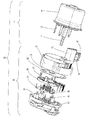
図1〜図3は、それぞれ本発明の実施の形態1に係る電動式駆動装置100の断面図、分解斜視図、回路図である。本発明の実施の形態1に係る電動式駆動装置100は、電動式パワーステアリング装置に用いられる電動式駆動装置であり、車両のステアリングに対して補助トルクを出力する電動モータ1と、この電動モータ1を駆動制御する制御装置20とを備えている。
Hereinafter,
1 to 3 are a sectional view, an exploded perspective view, and a circuit diagram, respectively, of the
電動モータ1は、三相ブラシレスモータであって、回転軸2と、回転軸2に例えば10極に着磁された円筒状の永久磁石3が固定された回転子4と、回転子4の周囲に設けられた固定子5と、固定子5を固定する鉄製のヨーク6と、回転軸2の端部に固定され、電動モータ1のトルクを伝達するカップリング7とを備えている。
固定子5は、永久磁石3の外周に相対した例えば12個の突極8と、突極8に装着されたインシュレータ9を介して巻回され、かつ、U、VおよびWの3相に接続された電機子巻線10を有している。電機子巻線10は、例えばΔ結線されており、各巻線端部は、絶縁性の樹脂材からなるド−ナツ形状のホルダ11により支持される3本のターミナル(中間部材)12U、12V、12Wと、それぞれ、かしめ、溶接等の接合手段にて接続される。なお、永久磁石3の極数を10極、固定子5の突極数を12個としたが、この組み合わせに限定されるものではなく、他の極数、突極数の組み合わせであってもよく、また、電機子巻線10は、Δ結線としたが、この場合に限らず、スター結線であっても良い。The
The
円環状のホルダ11には、同心円状に凹状の溝部(支持部)11aがターミナル12と同数形成されている。円弧形状の各ターミナル12は、溝部11aに支持されている。また、タ−ミナル12は、それぞれ、電動モータ1から制御装置20に向かって回転軸2の軸線と平行に延出するターミナル12と同数のモータ端子(第1の端子)13と、かしめ、溶接等の接合手段にて接続される。このとき、モータ端子13は、溝部11aよりも径方向外側に配置されている。
なお、ターミナル12は、モータ端子13に比べて耐熱クリープ特性が低い銅合金で作製されている。なお、クリープとは、一定の温度、一定の応力を受ける材料が、ある時間を過ぎた後に生じる変形のことであり、耐熱クリープ特性が高い材料とは、熱に対して、一定の応力を受けた材料の経時劣化度合い(変形度合い)が小さい材料のことである。The
The
ここで、図1、図4を参照しながら、モータ端子13について説明する。図4は、図1のモータ端子13の要部正面図である。
図4に示すように、モータ端子13は、例えば柱状であって、制御装置20側の端部にはスリット13aが形成されており、このスリット13aにより、二つの腕部13bが形成される。また、図1に示すように、電動モータ1側(スリット13aが形成された側とは反対側)の端部には、曲げ部13dにてL字状に曲げ加工されることで、回転軸2の軸方向に対して垂直な端面13eが形成されている。それぞれの腕部13bの先端部であって、スリットが形成されている側(モータ端子13の内側、図4参照)には、先端に向かってスリット幅Wが漸次大きくなる、すなわち、腕部13bの幅が漸次小さくなるテーパ13c1がスリット13aの両側に形成されている。端面13eは、ホルダ11の当接面11bに対して軸方向に当接して支持されている。なお、本実施の形態1では、腕部13bの先端部であって、スリット13aが形成されていない側(モータ端子13の外側、図4参照)にもテーパ13c2が形成されている。
また、モータ端子13は、車載用コネクタ等に使用される銅合金であって、後述するモータ接続端子34に比べて耐熱クリープ特性の高い、高導電、高強度の特殊銅合金の板材をプレス加工することで形成される。そして、プレス加工した後、プレス加工面には、例えば錫等にてメッキ処理が施されている。Here, the
As shown in FIG. 4, the
Further, the
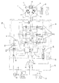
次に、制御装置20について説明する。電動モータ1を駆動制御する制御装置20は、半導体スイッチング素子23をモールド樹脂で封止してなるパワーモジュール(半導体モジュール)21およびリレーモジュール(半導体モジュール)60と、絶縁プリント基板からなる制御基板25と、半導体スイッチング素子23に接続される受動素子(コイル40、コンデンサ41)と、複数の導電板33が、絶縁性樹脂によりインサート成型されているフレーム30と、アルミダイカスト製のヒートシンク35と、車両のバッテリ50と電気的に接続されるパワーコネクタ37、外部配線を介して車両側と信号が入出力される信号コネクタ38、外部配線を介してトルクセンサ51からの信号が入出力されるトルクセンサコネクタ39と、ヨーク6を固定するアルミダイカスト製のハウジング36と、回転子4の回転位置を検出する回転位置センサであるレゾルバ29とを備えている。レゾルバ29は、レゾルバ用回転子29aおよびレゾルバ用固定子29bを有している。ここでは、回転位置センサをレゾルバ29とした場合について示したが、この場合に限らず、例えば、磁気抵抗素子、ホールIC等他の磁気検出素子を用いても良い。
Next, the
ここで、図1、図2および図5を参照しながら、パワーモジュール21について説明する。図5は、図1のパワーモジュール21の斜視図であって、(a)はパワーモジュール21単体の斜視図、(b)は(a)のパワーモジュール21にモータ接続端子34を溶接した後の斜視図である。
パワーモジュール21は、配線パターンが形成された、銅または銅合金製のリードフレーム22上に、補助トルクの大きさおよび方向に応じて電動モータ1のモータ電流IMを切り替えるための3相ブリッジ回路を構成するFET23a、3相ブリッジ回路から電動モータ1に供給されるモータ電流IMを通電・遮断するスイッチ手段であるモータリレーを構成するFET23b、3相ブリッジ回路と接地との間に挿入されるシャント抵抗器24が半田で実装されており、これを絶縁性樹脂にて内包して一体成型したトランスファーモールドタイプのモジュールである。
そして、図5(a)に示すように、パワーモジュール21には、内蔵するFET23aに給電するモジュールパワー端子22a、22bと、パワーモジュール21から電動モータ1へ給電するモジュールモータ接続端子22cと、FET23a、23bを制御するモジュール信号端子22dとを備えている。パワーモジュール21のモジュール信号端子22dは、後述する制御基板25のスルーホール25bに半田付けにより接続される。また、図5(b)に示すように、パワーモジュール21のモジュールモータ接続端子22cは、後述するフレーム30のモータ接続端子(第2の端子)34に溶接で接続される。さらに、モジュールパワー端子22a、22bは、後述するフレーム30の導電板33とそれぞれ溶接にて接合される。Here, the
The
As shown in FIG. 5A, the
リレーモジュール60は、リードフレーム22上に、バッテリ50からの電源電流IBを通電・遮断するスイッチ手段であるFET23cが半田で実装されており、パワーモジュール21と同様、このFET23cを絶縁性樹脂にて内包して一体成型したトランスファーモールドタイプのモジュールである。
本実施の形態1に係る電動式駆動装置の電動モータ1は、3相ブラシレスモータであり、また図1、図3からも分かるように、制御装置20は、パワーモジュール21を3個と、リレーモジュール60を1個の計4個の半導体モジュールを備えている。そして、図2に示すように、これら4個の半導体モジュールは、制御装置20の周方向に対して、略90度ピッチで等間隔に配置されている。In the
The
制御基板25は、多層(例えば4層)のガラスエポキシ基板からなり、モジュール信号端子22dの挿入されるスルーホール25bが設けられている。モジュール信号端子22dは、スルーホール25bに半田付けされることで、制御基板25の配線パターンと電気的に接続される。そして、制御基板25上には、トルクセンサ51からの操舵トルク信号に基づいて補助トルクを演算するとともに、モータ電流IMおよびレゾルバ29で検出された電動モータ1の回転子の回転位置をフィードバックして補助トルクに相当する電流を演算するマイクロコンピュータ26と、マイクロコンピュータ26からの指令によりFET23aを駆動する駆動信号を出力する駆動回路27と、シャント抵抗器24の一端と接続され、電動モータ1に流れるモータ電流IMを検出する電流検出手段28とが、半田付けされて実装されている。なお、マイクロコンピュータ26は、図示していないが、AD変換器やPWMタイマ回路等の他に、周知の自己診断機能を含み、システムが正常に作動しているか否かを常に自己診断しており、異常が発生するとモータ電流IMを遮断するようになっている。
The
また、電動モータ1を駆動する駆動部61は、電動モータ1の電流切り替えを行う半導体スイッチング素子23(FET23a)、スイッチング素子23に電気的に接続される受動素子(コイル40、コンデンサ41)、およびFET23aを駆動する駆動信号を出力する駆動回路27および周辺回路素子等からなる。コイル40は、半導体スイッチング素子23のスイッチング動作時に発生する電磁ノイズを除去するものであり、コンデンサ41は、電動モータ1に流れるモータ電流IMのリップル成分を吸収するものである。駆動回路27では、回転方向指令および電流制御量がマイクロコンピュータ26から入力されると、PWM駆動信号が生成され、FET23aに印加される。これにより、電動モータ1には、バッテリ50からの電源電流IBが、パワーコネクタ37、コイル40およびFET23a、23bを通じて流れ、所要方向に所要量の補助トルクが出力される。
なお、モータ電流IMには、FET23aのPWM駆動時のスイッチング動作によりリップル成分を含むが、コンデンサ41により平滑されて制御される。The driving
The motor current IM includes a ripple component due to the switching operation during PWM driving of the
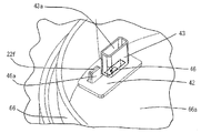
ここで、図1、図6を参照しながら、フレーム30について説明する。図6は、モータ端子13がモータ接続端子34に圧入された状態で固定される前であり、モータ端子13がガイド部31に接近した際の、フレーム30の要部斜視図であって、(a)はガイド部31の全体図、(b)はモータ接続端子34付近を示した図である。
フレーム30は、図1に示すように、パワーモジュール21のモジュールパワー端子22a、22b、コイル40、コンデンサ41、各種コネクタ(パワーコネクタ37、信号コネクタ38、トルクセンサコネクタ39)と電気的に接続される複数の導電板33を絶縁性樹脂にてインサート成型することで形成されている。導電板33は、回転軸2と垂直な平面上に構成されており、その一端がL字状に曲げ加工され、絶縁性樹脂から露出した接続部33aが形成されている。これらの接続部33aと、モジュールパワー端子22a、22b、各種コネクタ(パワーコネクタ37、信号コネクタ38、トルクセンサコネクタ39)、コイル40、コンデンサ41が溶接等の接合手段にて接続される。Here, the
As shown in FIG. 1, the
また、図6に示すように、モータ接続端子34は導電板33の一つであって、モータ端子13と同数あり、それぞれ、モータ端子13に電気的に接続されて、これらの導電板33とともに絶縁性樹脂にてフレーム30にインサート成型される、もしくはこれらの導電板33をインサート成型した後、例えばプレス加工にて導電板33から分断される、ことで形成されている。モータ接続端子34も、導電板33と同様、その一端がL字状に曲げ加工され、絶縁性樹脂から露出した接続部34aとモジュールモータ接続端子22cが溶接等の接合手段にて接続される。
モータ接続端子34には、図5(b)に示すように、モータ端子13の腕部13bが挿入される挿入孔34bが形成されており、挿入孔34b間の長さDは、モータ端子13のスリット幅W(図4参照)よりも大きい、すなわち、D>Wの関係を満たすようになっている。なお、腕部13bが挿入孔34bに挿入されることで、スリット13a(それぞれの腕部13bのモータ端子13の内側)がそれぞれの挿入孔34bの内側を挟み込むことから、挿入孔34b間の長さDは、モータ端子13に対する、モータ接続端子34の挟み込み幅に相当する。また、モータ接続端子34は、銅板を所定の形状(寸法)でプレス加工して形成されている。As shown in FIG. 6, the
As shown in FIG. 5 (b), the
また、フレーム30には、図6(a)に示すように、モータ端子13が挿入される挿入孔31aを有し、モータ端子13のスリット13aがモータ接続端子34を挟み込むことができるように、モータ端子13をガイドする絶縁性樹脂製のガイド部31が形成されている。そして、図6(b)に示すように、挿入孔31aは、軸方向に対して、電動モータ1側(入口)から反電動モータ1側(出口)に向かってガイド部31の軸方向断面が漸次狭くなるテーパ形状となっているので、モータ端子13が挿入孔31aを通過すると、モータ端子13の位置が矯正され、モータ接続端子34のある位置にモータ端子13をガイドすることができる。また、図1に示すように、フレーム30における、ガイド部31よりも外側でかつ、反電動モータ1側の端部には、回転軸2の軸線と垂直な端面30aが形成されている。
Further, as shown in FIG. 6A, the
ヒートシンク35は、フレーム30よりも反電動モータ1側に配置されており、ヒートシンク35の電動モータ1側には、パワーモジュール21が、伝熱性と絶縁性を両立する絶縁性部材、例えば、アルミナ、窒化ケイ素、窒化アルミニウムなどのセラミック板(図示せず)を介して密着して固定されている。セラミック板には伝熱性のグリスまたは接着剤が塗布されている。
また、ヒートシンク35のパワーモジュール21が固定されている面には、フレーム30がねじ(図示せず)で固定されている。フレーム30に配設された、コイル40およびコンデンサ41は、ヒートシンク35に形成された凹部35aに挿入されている。ヒートシンクに形成された凹部35aと、コイル40およびコンデンサ41との隙間には、伝熱性のグリスまたは接着剤が塗布されている。ヒートシンク35には、フレーム30の端面30aに当接して、フレーム30を支持する支持部35bが設けられている。The
The
ハウジング36は、回転軸2の軸線上に配置され、電動モータ1と制御装置20とを連結するものであり、制御装置20を構成するヒートシンク35とねじ(図示せず)で締結されている。ハウジング36は、ヒートシンク35とともにパワーモジュール21、制御基板25、フレーム30を覆っている。また、ハウジング36は、電動モータ1を構成するヨーク6とねじ(図示せず)で締結されている。なお、ハウジング36とヒートシンク35の間、ハウジング36と電動モータ1の間には、それぞれ液体パッキンが塗布されている。ハウジング36は、電動モータ1の回転軸2方向に垂直なプレート36aが一体成型されている。プレート36aは、電動モータ1、ヒートシンク35、ハウジング36にて囲まれる空間を分割している。なお、プレート36aには、電動モータ1と制御装置20とを連結する際、回転軸2が通過する貫通孔36bと、フレーム30に形成されたガイド部31が通過する貫通孔36cが形成されている。
The
続いて、図1、図2および図6を参照しながら、モータ端子13とモータ接続端子34の接続について説明する。図2に示すように、電動モータ1を組み上げた段階で、電動モータ1に設けられたモータ端子13は、電動モータ1から制御装置20に向かって回転軸2の軸線方向と平行に延出しており、モータ端子13のうち、制御装置20側端部には、腕部13bおよびスリット13aが形成されている。
また、制御装置20を組み上げた段階では、ハウジング36とヒートシンク35はねじで締結され、このとき、フレーム30に形成されたガイド部31は、ハウジング36に形成された貫通孔36cを通過し、電動モータ1に向かって延出しており、制御装置20に設けられたモータ接続端子34は、図1に示すように、導電板33とともにフレーム30にインサート成型されている。
そして、電動モータ1が回転軸2の軸線方向で制御装置20に向かい、制御装置20とねじで締結されたハウジング36が電動モータ1のヨーク6とねじで締結され、電動モータ1、制御装置20の両者を組み付けるタイミングで、モータ端子13は、ガイド部31の挿入孔31aに挿入される。挿入孔31aの反電動モータ1側には、モータ接続端子34が位置して固定されており、モータ端子13の腕部13bは、モータ接続端子34の挿入孔34bに挿入されて、モータ端子13に形成されたスリット13aがモータ接続端子34を挟み込むことで、モータ端子13はモータ接続端子34に圧入される。その結果、両端子は圧接状態で電気的に接続される。それゆえ、電動モータ1と制御装置20を組み付けるタイミングでモータ端子13はモータ接続端子34に圧入された状態で固定される。このとき、モータ端子13のスリット13aは、図1に示すように、フレーム30、パワーモジュール21およびヒートシンク35によって、その周囲が取り囲まれた空間(閉空間)内に位置して固定されている。Subsequently, the connection between the
At the stage of assembling the
Then, the
以上説明したように、本発明の実施の形態1に係る電動式駆動装置100によれば、制御装置20が電動モータ1の回転軸2の軸線上に配置され、電動モータ1または制御装置20のうち、一方である電動モータ1には、他方である制御装置20に向かって延出するモータ端子(第1の端子)13を有し、このモータ端子13のうち、制御装置20側端部(他方側端部)にスリット13aが形成され、また、制御装置20には、モータ端子13の延出線上に設けられ、モータ端子に電気的に接続されるモータ接続端子(第2の端子)34を有している。そして、スリット13aがモータ接続端子34を挟み込むことで、モータ端子13は、モータ接続端子34に圧入されて、両端子は電気的に接続されている。
これにより、両端子間の接続にネジ等の部品を新たに必要としないので、部品点数が削減され、ネジを締結する工程も不要となるので、組立工数が削減され、その結果、コストを低減することができる。また、ネジ締結のために、ネジの配置スペースおよびネジ締結用の挿入スペースを別途確保していた場合と比べると、これらのスペースも不要となるので、電動式駆動装置を小型化することができる。
また、端子間を接続するネジが不要となったことから、ネジ締結用ツールの挿入口を塞ぐカバーも不要となるので、部品点数および組立工数が削減され、さらにコストを低減することができる。
また、モータ端子13の腕部13bがモータ接続端子34の挿入孔34bに挿入される際、少なくとも腕部13bのモータ端子13の内側が、おのおのモータ端子13の外側方向にたわんで、腕部13bのモータ端子13の内側が、モータ接続端子34の挿入孔34b間(長さD、D>W)を挟み込むことから、モータ端子13の腕部13bの幅に寸法ばらつきが生じて、腕部13bのモータ端子13の外側と挿入孔34bとの間に多少の隙間があった場合であっても、モータ端子13とモータ接続端子34とは電気的に接続されるので、モータ端子13の寸法ばらつきを吸収することができ、電動式駆動装置の生産性が向上する。
さらに、電動モータ1と制御装置20を組み付けるタイミングで、モータ端子13はモータ接続端子34に圧入された状態で固定されることから、電動式駆動装置の組立性が向上する。As described above, according to
This eliminates the need for new parts such as screws for the connection between both terminals, so the number of parts is reduced and the process of fastening the screws is not required, reducing the number of assembly steps and consequently reducing costs. can do. In addition, compared to a case where a screw arrangement space and a screw fastening insertion space are separately secured for screw fastening, these spaces are not required, and the electric drive device can be miniaturized. .
Further, since the screws for connecting the terminals are not required, a cover for closing the insertion port of the screw fastening tool is also unnecessary, so that the number of parts and the number of assembling steps can be reduced, and the cost can be further reduced.
Further, when the
Further, since the
なお、実施の形態1においては、第1の端子が電動モータ1のモータ端子13であり、第2の端子が制御装置20のモータ接続端子34である場合について示したが、これらの端子が逆の構成である、すなわち、第1の端子が制御装置のモータ接続端子であり、第2の端子が電動モータのモータ端子であっても良い。この場合であっても、第1の端子であるモータ接続端子のうち、電動モータ側端部にスリットが形成され、このスリットが第2の端子であるモータ端子を挟み込むことで、モータ接続端子は、モータ端子に圧入されて、両端子は電気的に接続されるので、これにより、両端子間の接続にネジ等の部品を新たに必要としないので、部品点数が削減され、ネジを締結する工程も不要となるので、組立工数が削減され、その結果、コストを低減することができる。
In the first embodiment, the case where the first terminal is the
また、実施の形態1に係る電動式駆動装置100において、モータ端子13の制御装置20側の端部に形成されるスリット13aは、先端が二つに分かれ、二つの腕部13bが形成される場合について示したが、この場合に限らず、同一平面上で三つあるいはそれ以上に分かれ、三つあるいはそれ以上の腕部が形成されるようにしても良い。この場合、モータ端子、モータ接続端子間の圧入箇所が増加することから、圧入力も増加し、より確実に圧入される。また、モータ端子の先端が、十字形状またはH字形状等のように、複数の平面上で複数に分かれて、腕部が形成される場合であっても、モータ端子の腕部がモータ接続端子の挿入孔を四方より挟み込むことでモータ端子がモータ接続端子に圧入されることから、同様の効果が得られる。
Moreover, in the
また、本発明の実施の形態1に係る電動式駆動装置100の制御装置20は、電動モータ1の電流切り替えを行う半導体スイッチング素子23(FET23a)および半導体スイッチング素子23に電気的に接続される受動素子(コイル40、コンデンサ41)からなる、電動モータ1を駆動する駆動部61と、受動素子の各端子がそれぞれ接続される複数の導電板33が絶縁性樹脂によりインサート成型されるとともに、受動素子が配設されたフレーム30とを備えた構成であることから、制御装置20の組み立て段階において、受動素子の溶接等の接合手段で一括して行うことが可能であり、受動素子の組み付け時間が短縮されることから、電動式駆動装置の組立性が向上する。
受動素子は、フレーム30のヒートシンク35側(フレーム30の一方)に配設されているので、受動素子の配設スペースを効率的に確保することができることから、電動式駆動装置の小型化を図ることができる。
なお、実施の形態1においては、パワーモジュール21のモジュールパワー端子22a、22bはフレーム30の導電板33と、パワーモジュール21のモジュールモータ接続端子22cはフレーム30のモータ接続端子34と、それぞれ接続されるので、上記の受動素子に加えて、パワーモジュール21の端子(モジュールパワー端子22a、22bとモジュールモータ接続端子22c)についても溶接等の接合手段で一括して行うことが可能であり、電子部品(受動素子、パワーモジュール)の組み付け時間が短縮されることから、電動式駆動装置の組立性がさらに向上する。In addition, the
Since the passive element is disposed on the
In the first embodiment, the
また、モータ端子13のスリット13aにより二つの腕部13bが形成され、それぞれの腕部13bの先端部であって、モータ端子13の内側には、先端に向かってスリット幅が漸次大きくなるテーパ13c1がスリット13aの両側に形成されているので、モータ端子13のスリット13aがモータ接続端子34を挟み込む際、モータ端子13の内側(スリット13aが形成される側)に形成されたテーパ13c1部分がモータ接続端子34に形成された挿入孔34b間に誘導するガイドの役割をし、モータ接続端子34をスムーズに挟み込むことができることから、電動式駆動装置の組立性が向上する。
その上、本発明の実施の形態1においては、腕部13bの先端部であって、モータ端子13の外側(スリット13aが形成されていない側)にもテーパ13c2が形成されているので、このテーパ13c2がモータ接続端子34に形成された各挿入孔34b内に誘導するガイドの役割をし、モータ接続端子34は挿入孔34b内にスムーズに挿入されるので、モータ端子13のスリット幅W、モータ接続端子34の挿入孔34b間の長さDの寸法ばらつきを吸収することができる。Further, two
In addition, in the first embodiment of the present invention, the taper 13c2 is formed on the outer end of the
また、モータ端子13の電動モータ1側(スリット13aが形成された側とは反対側)の端部には、曲げ部13dにてL字状に曲げ加工されることで、回転軸2の軸方向と垂直な端面13eが形成されており、この端面13eは、当接部材であるホルダ11の当接面11bに当接して支持されているので、モータ端子13とモータ接続端子34との圧入時に、モータ端子13に加わる荷重を、当接面11bを介してホルダ11全体で受けることになり、モータ端子13の変形量(たわみ量)は、モータ端子13に加わる全荷重を端面13eのみで受ける場合に比べて小さくなることから、モータ端子13が座屈等で変形を生じる場合が少なくなり、信頼性の向上した電動式駆動装置を提供することができる。
その上、モータ端子13の端面13eをホルダ11の当接面11bに当接させることで、モータ端子13が固定されるので、ターミナル12とモータ端子13とをかしめ、溶接等の接合手段で接続する際、モータ端子13の位置ずれが小さくなり、電動式駆動装置の組立性および信頼性が向上する。
また、モータ端子13がモータ接続端子34に圧入されて固定された後の電動式駆動装置100において、電動式駆動装置の振動や温度変化により材料に線膨張差等が生じ、このとき、モータ端子13の圧入力を弱める応力が生じるが、モータ端子13を曲げ加工することで曲げ部13dがL字状に形成され、これがモータ端子13の弾性部を形成することから、電動式駆動装置の振動、モータ端子13の線膨張差等により生じる応力が緩和され、電動式駆動装置の信頼性が向上する。Further, the end of the
In addition, since the
Further, in the
また、モータ端子13は、モータ接続端子34に比べて耐熱クリープ特性の高い銅合金で作製されているので、圧入固定部の経時劣化度合いが小さくなり、信頼性の向上した電動式駆動装置を提供することができる。本発明の実施の形態1においては、モータ端子13は、モータ接続端子34に比べて耐熱クリープ特性の高い銅合金であって、さらに高導電、高強度の特殊銅合金で作製されていることから、圧入固定部の経時劣化度合いが小さいことに加えて、モータ端子の発熱量も少なく、また強度も高くなることから、さらに信頼性の向上した電動式駆動装置を提供することができる。
In addition, since the
また、モータ端子13は、中間部材であるターミナル12を介して電機子巻線10に、かしめ、溶接等の接合手段にて電気的に接続されており、ターミナル12は、モータ端子13に比べて耐熱クリープ特性が低い銅合金で作製されている。一般に、耐熱クリープ特性が高い銅合金は特殊材料であり、変形等に対する経時劣化度合いが小さい反面、高価であることから、モータ端子と電機子巻線とを溶接等の接合手段にて直接電気的に接続した場合、特殊材料の使用量が増加して高コストになる。しかし、実施の形態1においては、モータ端子13のうち、圧入固定部以外の一部は、圧入固定部に比べて耐熱クリープ特性を必要としないことから、この部分を圧入固定部に比べて耐熱クリープ特性の低いターミナル12で構成し、圧入固定部のみをモータ端子13で構成したことで、特殊材料の使用量が低減し、電動式駆動装置のコストが低減する。
Further, the
また、本発明の実施の形態1に係る電動モータ1は、三相モータであって、ホルダ11には、ターミナル12を支持する支持部11aが形成され、3本のターミナル12U、12V、12Wと3本のモータ端子13U、13V、13Wは、それぞれかしめ、溶接等の接合手段にて接続されており、各モータ端子13は、この支持部11aより径方向外側に配置されているので、支持部11aより径方向内側に配置される場合に比べて、各モータ端子13について、他相のターミナル12間との絶縁距離を広げることができ、電動式駆動装置の信頼性が向上する。また、モータ端子13とターミナル12の接合部位が径方向外側に配置されるので、接合手段にて両者を接続する際に必要なスペースを確保することができ、電動式駆動装置の組立性も向上する。
さらに、モータ接続端子34は、モータ端子13の延出線上に設けられて、モータ端子13の圧入を受けるものであって、3本のモータ端子13は、支持部11aより径方向外側に配置されているので、3本のモータ端子13それぞれの延出線上に設けられた3本のモータ接続端子34についても、径方向外側に配置されることから、3本のモータ接続端子34は、3本のモータ端子13の圧入を、径方向内側であって、回転軸2付近で集中して受けることなく、径方向外側で、圧入荷重を分散して受けることができるので、電動式駆動装置の信頼性が向上する。また、モータ接続端子34の絶縁距離を確保することができ、さらに電動式駆動装置の信頼性が向上する。In addition, the
Furthermore, the
また、本発明の実施の形態1に係る制御装置20は、3個のパワーモジュール21と1個のリレーモジュールの計4個の半導体モジュールを備えており、これらは、制御装置20の周方向に対して、略90度ピッチで等間隔に配置され、3個のパワーモジュール21に対応して、3本のモータ端子13U、13V、13Wも略90度ピッチで等間隔に配置されている。このように、3本のモータ端子13を90度ピッチで等間隔に配置することで、各モータ端子13間の絶縁距離を十分に確保することができることから、電動式駆動装置の信頼性が向上する。
In addition, the
また、フレーム30には、モータ端子13が挿入されるガイド部31が形成されているので、モータ端子13がモータ接続端子34を挟み込む際、ガイド部31はモータ端子13の位置をモータ接続端子34のある位置に矯正するガイドの役割をすることから、モータ端子13は、ガイド部31のガイドに従ってモータ接続端子34を挟み込むことができ、電動式駆動装置の組立性が向上する。
なお、実施の形態1では、ガイド部31は、フレーム30とは別部品にて構成した場合について示したが、この場合に限らず、フレーム30、ガイド部31はともに絶縁性樹脂にて成型されるものであることから、両者を一体成型することができる。フレーム30とガイド部31を絶縁性樹脂にて一体成型することで、組立工数が削減され、コストを低減することができる。その上、両部品を別部品にて構成した場合に比べて、ガイド部31の位置精度が向上することから、電動式駆動装置の組立性がさらに向上するとともに、電動式駆動装置の信頼性が向上する。
さらに、実施の形態1において、ガイド部31は、図6に示すように、モータ端子13の周囲を覆うように形成されているので、絶縁性を確保することができ、電動式駆動装置の信頼性がさらに向上する。In addition, since the
In the first embodiment, the case where the
Furthermore, in
また、モータ接続端子34は、絶縁性樹脂にてフレーム30にインサート成型されているので、フレーム30を構成する際、絶縁性樹脂によりモータ接続端子34の両端は固定されることから、モータ端子13がモータ接続端子34に圧入された状態で固定される際、圧入時にモータ接続端子34に加わる荷重が、偏ることなく均等にかかるとともに、モータ接続端子34が受ける荷重をフレーム30全体で受けることができ、モータ接続端子34の変形、破損を防ぐことができる。これにより、電動式駆動装置の信頼性が向上する。
モータ接続端子34が、絶縁性樹脂にてフレーム30にインサート成型されると、モータ接続端子34の位置が固定されるので、モータ接続端子34の位置ずれが小さくなり、モータ端子13はモータ接続端子34を確実に挟み込むことができることから、電動式駆動装置の組立性が向上する。
さらに、フレーム30には、モータ端子13が挿入されるガイド部が形成されており、このガイド部31により、モータ端子13はフレーム30に対する相対位置が一意に決まるとともに、上述したように、モータ接続端子34についても、フレーム30に対する相対位置が一意に決まる。よって、フレーム30に対して、モータ端子13、モータ接続端子34の相対位置が一意に決まり、両者の位置ずれが小さくなることから、電動式駆動装置の組立性・信頼性がさらに向上する。
その上、モータ接続端子34に加えて、ガイド部31もフレーム30にインサート成型されることで、組立工数が削減され、コストを低減することができるとともに、フレーム30に対して、モータ接続端子34、ガイド部31の相対位置が一意に決まり、ガイド部31とモータ接続端子33の位置ずれが小さくなることから、両者の位置精度が向上して、電動式駆動装置の組立性・信頼性が向上する。なお、モータ接続端子34がフレーム30にインサート成型されることで、組立工数が削減され、コストを低減することができる。Further, since the
When the
Further, the
In addition to the
なお、パワーモジュール21のリードフレーム22は、打ち抜き等により所要の形状にプレス加工されたものに、FET23a、23bおよびシャント抵抗器24が搭載され、これをモールド樹脂で封止した後、不要な部分が除去されて、FET23a、23bが搭載される面に垂直な方向に折り曲げられる(図5のモジュールパワー端子22a、22b、モジュールモータ接続端子22c、モジュール信号端子22d参照)。
プレス加工される前のリードフレーム22の形状は、リードフレーム22を折り曲げる前の形状であるため、一般に、リードフレームの長さが長いと、不要な部分も増加することから、リードフレームのコストが増加するが、実施の形態1において、モータ接続端子34は、パワーモジュール21が配設されるフレーム30にインサート成型されており、リードフレーム22のうち、モジュールモータ接続端子22cは、このモータ接続端子34に溶接等の接合手段により接続されるので、モジュールモータ接続端子22cの長さが短くなり、その分リードフレーム22の材料使用量が低減することから、コストを低減することができる。Note that the
Since the shape of the
また、フレーム30における、ガイド部31よりも外側でかつ、反電動モータ1側の端部には、回転軸2の軸線と垂直な端面30aが形成されており、この端面30aは、支持部材であるヒートシンク35に設けられた支持部35bに当接して、ヒートシンク35は、ガイド部31が形成されたフレーム30を支持する構成であるので、モータ端子13がガイド部31に挿入される際に、フレーム30が受ける荷重を、支持部35bを介してヒートシンク35全体で受けることになり、フレーム30のたわみ量は、フレーム30に加わる全荷重を端面30aのみで受ける場合に比べて、小さくなることから、フレーム30の変形、破損を防ぐことができる。これにより、電動式駆動装置の信頼性が向上する。
その上、モータ接続端子34がフレーム30にインサート成型されることで、組立工数が削減され、コストを低減することができるとともに、モータ端子13とモータ接続端子34との圧入時に、モータ接続端子34が受ける荷重をフレーム30全体で受けることができることから、圧入によりモータ接続端子34が変形することがなくなり、信頼性の向上した電動式駆動装置を提供することができる。Further, an
In addition, since the
また、モータ接続端子34は、JIS規格に準じた銅板(例.板厚1mmの薄板)の板厚部分ではなく、銅板の平面部分を所定の形状(寸法)でプレス加工して形成されているので、電動モータ1の出力、使用環境、用途に応じて、モータ接続端子34の挟み込み幅(挿入孔34b間の長さD)を任意に設定することができることから、電動式駆動装置の設計自由度が向上する。また、モータ端子13についても、銅合金の板材をプレス加工することで形成されているので、モータ接続端子34と同様、電動モータ1の出力、使用環境、用途に応じて、モータ端子13の形状(例.スリット幅W<D)を任意に設定することができることから、電動式駆動装置の設計自由度が向上する。
In addition, the
また、モータ端子13は、板材をプレス加工した後、プレス加工面にメッキ処理が施されているので、モータ端子13のメッキ部分は、モータ端子13の腕部13bがモータ接続端子34の挿入孔34b間を挟み込んだ後の、両端子間に生じる微細な隙間を埋めるように作用することから、両端子間に生じる接触抵抗の増加が抑制されて、電動式駆動装置の性能が向上する。なお、モータ端子13の代わりに、モータ接続端子34にメッキ処理が施される構成、あるいは両端子にメッキ処理が施される構成も可能であり、これらの構成であっても、それぞれ程度の差異はあるものの、両端子間に生じる接触抵抗の増加が抑制される効果が得られることは言うまでもない。
さらに、本発明の実施の形態1に係る電動モータ1は、三相モータであって、3本のモータ端子13U、13V、13Wは、板材をプレス加工することで個々に形成されて、3つのモータ接続端子34U、34V、34Wにそれぞれ圧入される。これに対して、3つのモータ接続端子34(34U、34V、34W)は、銅板をプレス加工することで、例えば、コイル40等の受動素子への接続部を備えた一体品で形成されて、絶縁性樹脂にてインサート成型される。一体品であるモータ接続端子34は、メッキ処理の不要な箇所が含まれており、大型であるため、必要箇所にメッキ処理を施す場合、高コストになるおそれがある。これに対して、個々に形成されるモータ端子13は、小型で、端子全体にメッキ処理を施すので、低コストで施すことができることから、装置のコストが低減する。
モータ接続端子34のメッキ処理後、インサート成型される場合、インサート成型時にメッキ被膜の溶出により、モータ接続端子34の電気的信頼性を損なうおそれがあるが、モータ端子13は、メッキ処理後、モータ接続端子34に圧入されるので、この点においても、モータ端子13にメッキ処理を施す方が性能面・コスト面で有利である。
その上、両端子にメッキ処理を施した場合であれば、両端子のメッキ部分同士が接触しながら挿入されて、モータ端子13がモータ接続端子34を挟み込むので、挿入がスムーズになり、また、両端子はメッキ部分に覆われているので、端子表面が削られにくくなる。それゆえ、両端子の表面積は、端子表面が削られた場合に比べて小さいことから、端子表面は酸化しにくく、両端子の寿命が長くなり、装置の長寿命化を図ることができる。Further, since the
Furthermore, the
When insert molding is performed after the plating of the
In addition, if both terminals are plated, the plated portions of both terminals are inserted while contacting each other, and the
また、駆動部61を構成するコイル40、コンデンサ41等の受動素子や半導体スイッチング素子23は発熱部品であり、コイル40、コンデンサ41は、ヒートシンク35に形成された凹部35aに挿入され、半導体スイッチング素子21をモールド樹脂で封止してなる半導体モジュール(パワーモジュール21、リレーモジュール60)は、伝熱性を有するセラミック板を介して密着して固定されているので、発熱部品(コイル40、コンデンサ41、半導体モジュール)からの発熱は、ヒートシンク35にて放熱されて、電動式駆動装置の放熱性能が向上する。よって、発熱部品にて発熱した際の温度上昇が抑制されるので、電動式駆動装置の信頼性が向上する。
発熱部品のうち、コイル40、コンデンサ41については、ヒートシンク35に形成された凹部35aに挿入されているので、コイル40、コンデンサ41からの発熱は、ヒートシンク35側の軸方向端面に加えて、外周面からもヒートシンク35に伝熱して放熱されることから、ヒートシンク35側の軸方向端面のみからヒートシンク35に伝熱して放熱される場合に比べて、電動式駆動装置の放熱性能が向上する。
なお、実施の形態1では、セラミック板に伝熱性のグリスまたは接着剤を塗布することで、部品間の接着熱抵抗が低減し、またコイル40、コンデンサ41とヒートシンク35の凹部35aとの隙間に、伝熱性のグリスまたは接着剤を塗布することで、コイル40、コンデンサ41からヒートシンク35への放熱が促進されるので、電動式駆動装置の放熱性能がさらに向上する。In addition, the passive element such as the
Among the heat generating components, the
In the first embodiment, by applying thermally conductive grease or adhesive to the ceramic plate, the adhesive thermal resistance between components is reduced, and the gap between the
また、電動モータ1と制御装置20を組み付けることで電動式駆動装置100は形成されて、モータ端子13が電動式駆動装置100の内部にあることから、外部からモータ端子13部分への、異物の侵入を防ぐことができるとともに、組み付けのタイミングで、モータ端子13のスリット13a(腕部13b)は、フレーム30、パワーモジュール21およびヒートシンク35により、その周囲が取り囲まれた空間(閉空間)内に位置して固定されているので、例えば、外部から電動モータ1内に侵入した異物(ゴミや水滴等)が、たとえフレーム30部分にまで到達したとしても、フレーム30により、スリット13a(腕部13b)部分にまで侵入することを防ぐことができることから、圧入固定部の防水性、絶縁性を確保することができる。また、圧入時に発生したカス等が、例えば、電動モータ1の回転子4等へ流出することも防ぐことができる。
Moreover, since the
また、ハウジング36とヒートシンク35の間、ハウジング36と電動モータ1の間には、それぞれ液体パッキングが塗布されているので、これらの間をシーリングすることができ、電動式駆動装置の防水性が向上する。なお、実施の形態1においては、ハウジング36とヒートシンク35(電動モータ1)との間の防水構造を液体パッキングとしたが、これに限定されるものではなく、例えば、Oリングやゴムパッキンであっても良い。
In addition, since liquid packing is applied between the
また、ヒートシンク35とパワーモジュール21との間にある絶縁性部材は、セラミック板としたが、これに限定されるものではなく、例えば、アルミナ等の高熱伝導材をフィラーとして混入させた接着剤やシリコン等の素材による放熱絶縁シートであっても良い。
The insulating member between the
実施の形態2.
実施の形態2に係る電動式駆動装置200の構造について、図7〜図9を用いて説明する。図7は本発明の実施の形態2に係る電動式駆動装置200の断面図、図8は図7のパワーモジュール62の斜視図、図9はモータ端子13がモータ接続端子45に圧入された状態で固定される前であり、モータ端子13が開口部62aに接近した際の、パワーモジュール62の要部斜視図である。
図7〜図9に示すように、実施の形態2に係る電動式駆動装置200は、パワーモジュール62の構成が実施の形態1で示したパワーモジュール21とは異なる。また、このパワーモジュールの変更に伴い、フレーム63の形状も実施の形態1で示したフレーム30とは異なる。他の構成は上記実施の形態1の電動式駆動装置100と同様であるので、詳細説明は省略する。
The structure of the
As shown in FIGS. 7 to 9, the
図8に示すように、パワーモジュール62には、第1の端子であるモータ端子13が挿入される開口部62aが形成されており、この開口部62aの内側に位置してリードフレーム22であるモジュールモータ接続端子22eが固定されている。開口部62aは、モータ端子13が挿入される側からモジュールモータ接続端子22eに向かって開口部62aの断面が漸次狭くなるテーパ形状となっている。
そして、モータ端子13は、このモジュールモータ接続端子22eを挟み込むことで、圧入された状態で固定され、両者は電気的に接続される。それゆえ、モジュールモータ接続端子22eは第2の端子であるモータ接続端子45と一体化して構成されている。したがって、モータ接続端子45は、パワーモジュール62と一体成型されている。As shown in FIG. 8, the
The
フレーム63は、パワーモジュール62のモジュールパワー端子22a、22b、コイル40、コンデンサ41、各種コネクタ(パワーコネクタ37、信号コネクタ38、トルクセンサコネクタ39)と電気的に接続される複数の導電板33を絶縁性樹脂にてインサート成型することで形成されている。
The
以上説明したように、本発明の実施の形態2に係る電動式駆動装置200は、図7〜図9に示すように、半導体スイッチング素子(FET23a、23b)をモールド樹脂で封止してなる半導体モジュール(パワーモジュール62)をさらに備え、パワーモジュール62に、モータ端子(第1の端子)13が挿入される開口部62aを設け、モータ接続端子(第2の端子)45を開口部62aの内側に位置して固定されるように構成したので、パワーモジュールのリードフレームは、配線パターンが形成されるものであり、通常、パワーモジュールの外部に露出しているが、リードフレーム22のうち、モジュールモータ接続端子22eは、パワーモジュール62の開口部62aの内側に位置して固定されるので、モジュールモータ接続端子eが外部に露出することなく、その分リードフレーム22の材料使用量が低減することから、コストを低減することができる。
As described above, the
また、モータ接続端子45は、モジュールモータ接続端子22eとして、リードフレーム22上に形成されているので、上記実施の形態1のように、モジュールモータ接続端子22cとは別部品として、モータ接続端子34を準備する必要がなく、実施の形態1の場合に比べて、部品点数を削減することができる。また、モータ接続端子34とモジュールモータ接続端子22cを接続する作業も不要であるので、組立工数も削減することができる。それゆえ、部品点数および組立工数が削減され、コストを低減することができる。
Since the
また、モータ接続端子45は、パワーモジュール62と一体成型されているので、半導体スイッチング素子であるFET23a、23bをモールド樹脂で封止して、パワーモジュール62を構成する際、リードフレーム22であるモータ接続端子45の両端は、モールド樹脂により固定されることから、モータ端子13がモータ接続端子45に圧入された状態で固定される際、圧入時にモータ接続端子45に加わる荷重が、偏ることなく均等にかかるとともに、モータ接続端子45が受ける荷重を、モールド樹脂を介してパワーモジュール62全体で受けることができ、モータ接続端子45の変形、破損を防ぐことができる。これにより、電動式駆動装置の信頼性が向上する。
また、モータ接続端子45がパワーモジュール62と一体成型されると、モータ接続端子45の位置が固定されるので、モータ接続端子45の位置ずれが小さくなり、モータ端子13はモータ接続端子45を確実に挟み込むことができることから、電動式駆動装置の組立性が向上する。Further, since the
Further, when the
また、上記実施の形態1の場合と同様、ヒートシンク35は、フレーム63よりも反電動モータ1側に配置されており、ヒートシンク35の電動モータ1側には、パワーモジュール62が、セラミック板を介して密着して固定されている。そして、ヒートシンク35のパワーモジュール62が固定されている面には、フレーム63がねじ(図示せず)で固定されており、このねじを締結することで、フレーム63がヒートシンク35に押圧された状態で固定される。それゆえ、ねじの締結力を利用して、フレーム63がヒートシンク35に押圧された状態で固定されると、パワーモジュール62およびパワーモジュール62の開口部62aに位置して固定されたモータ接続端子45の位置が固定されるので、モータ接続端子45の位置ずれが小さくなり、モータ端子13はモータ接続端子45を確実に挟み込むことができることから、電動式駆動装置の組立性が向上する。
As in the case of the first embodiment, the
また、開口部62aは、モータ端子13が挿入される側からモータ接続端子45に向かって開口部62aの断面が漸次狭くなるテーパ形状となっているので、モータ端子13が開口部62a内に挿入されると、モータ端子13の位置をモータ接続端子45のある位置に誘導することができる。それゆえ、モータ端子13は、開口部62aのテーパに従ってモータ接続端子45を挟み込むことができ、電動式駆動装置の組立性が向上する。なお、実施の形態1の場合と同様、フレーム63には、モータ端子13が挿入されるガイド部31が形成されているので、開口部62aのテーパとフレーム63に形成されたガイド部31を併用することで、モータ端子13の位置をモータ接続端子45に精度よく誘導することができ、位置ずれを小さくすることができるので、動式駆動装置の組立性がさらに向上する。
Further, since the
実施の形態3.
上記各実施の形態において、第1の端子であるモータ端子は、電動モータから制御装置に向かって回転軸の軸線方向と平行に延出するとともに、第2の端子であるモータ接続端子に圧入された状態で固定されている。また、第2の端子であるモータ接続端子は、フレームにインサート成型されたり、パワーモジュールの開口部の内側に位置して固定されたりしている。そして、フレームやパワーモジュールは制御装置内であり、電動モータから比較的離れた位置にあるため、モータ端子の長さは、その断面積に比べて十分に長い。それゆえ、モータ端子とモータ接続端子との圧入時に、長い柱状のモータ端子に荷重が加わると、モータ端子が座屈等で変形を生じる場合がある。実施の形態3では、電動モータと制御装置とを連結するハウジングの電動モータ側に、絶縁性部材が位置して固定され、モータ接続端子が、この絶縁性部材を介してハウジングに固定されることで、モータ端子が短くなることから、モータ端子13が座屈等で変形を生じる場合が少なくなり、信頼性の向上した電動式駆動装置を提供することができる。
In each of the above embodiments, the motor terminal that is the first terminal extends in parallel with the axial direction of the rotating shaft from the electric motor toward the control device, and is press-fitted into the motor connection terminal that is the second terminal. It is fixed in the state. Further, the motor connection terminal as the second terminal is insert-molded in the frame, or is fixed inside the opening of the power module. Since the frame and the power module are in the control device and are relatively far from the electric motor, the length of the motor terminal is sufficiently longer than its cross-sectional area. Therefore, when a load is applied to the long columnar motor terminal during press-fitting between the motor terminal and the motor connection terminal, the motor terminal may be deformed due to buckling or the like. In the third embodiment, the insulating member is positioned and fixed on the electric motor side of the housing connecting the electric motor and the control device, and the motor connection terminal is fixed to the housing via the insulating member. Thus, since the motor terminal is shortened, the
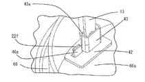
実施の形態3に係る電動式駆動装置300の構造について、図10〜図13を用いて説明する。図10は本発明の実施の形態3に係る電動式駆動装置300の断面図、図11は図10のハウジング66の要部斜視図であって、(a)はパワーモジュール64のモジュールモータ接続端子22f付近の要部斜視図、(b)は(a)のモジュールモータ接続端子22fにモータ接続端子46を溶接した後の要部斜視図、図12は図10の電動式駆動装置300において、電動モータ1と制御装置20とが連結される前の、ハウジング66の要部斜視図である。また、図13はモータ端子13がモータ接続端子46に圧入された状態で固定される前であり、モータ端子13がガイド部43に接近した際の絶縁性部材42の要部斜視図である。
図10〜図13に示すように、実施の形態3に係る電動式駆動装置300は、モータ接続端子46の位置が、実施の形態1、2で示したモータ接続端子(34、45)とは異なる。また、このモータ接続端子46の位置の変更に伴い、ハウジング66、パワーモジュール64およびフレーム65の形状も実施の形態1、2で示したハウジング36、パワーモジュール(21、62)およびフレーム(30、63)とは異なる。他の構成は上記実施の形態1、2の電動式駆動装置(100、200)と同様であるので、詳細説明は省略する。The structure of the
As shown in FIGS. 10 to 13, in the
ハウジング66は、図10、図11(a)に示すように、電動モータ1の回転軸2方向に垂直なプレート66aが一体成型されている。そして、プレート66aには、電動モータ1と制御装置20とを連結する際、回転軸2が通過する貫通孔66bと、後述の絶縁性部材42を圧入された状態で固定するための貫通孔66cが形成されている。
また、パワーモジュール64を構成するリードフレーム22のうち、モジュールモータ接続端子22fは、フレーム65に形成された貫通孔65aを通過して、ハウジング66の電動モータ1側に延出している。As shown in FIGS. 10 and 11A, the
Of the
絶縁性部材42は、例えば、絶縁性樹脂製の部材であり、図12に示すように、ハウジング66の電動モータ1側に位置して、上述したように、ハウジング66に設けられた貫通孔66cに、圧入された状態で固定される。絶縁性部材42には、絶縁性部材42自体が制御装置20側へ移動するのを抑制するストッパの役割をするフランジ42aが形成されている。
また、絶縁性部材42には、モータ端子13が挿入される挿入孔43aを有し、モータ端子13のスリット13aがモータ接続端子46を挟み込むことができるように、モータ端子13をガイドする絶縁性樹脂製のガイド部43が形成されている。そして、挿入孔43aは、軸方向に対して、電動モータ1側(入口)から制御装置20側(出口)に向かってガイド部43の軸方向断面が漸次狭くなるテーパ形状となっているので、モータ端子13が挿入孔43aを通過すると、モータ端子13の位置が矯正され、モータ接続端子46のある位置にモータ端子13をガイドすることができる。
また、絶縁性部材42は、モータ接続端子46をインサート成型されて形成されている。モータ接続端子46は、回転軸2と垂直な平面上に構成されており、その一端がL字状に曲げ加工され、絶縁性部材42から露出した接続部46aが形成されている。そして、図11(b)に示すように、接続部46aとモジュールモータ接続端子22fが溶接等の接合手段にて接続される。The insulating
The insulating
The insulating
以上説明したように、本発明の実施の形態3の電動式駆動装置300は、回転軸2の軸線上に配置され、電動モータ1と制御措置20とを連結するハウジング66をさらに備え、ハウジング66の電動モータ1側には、絶縁性部材42が位置して固定され、モータ接続端子(第2の端子)46は、絶縁性部材42を介してハウジング66に固定されるように構成したので、絶縁性部材42は、電動モータ1と制御装置20の間、すなわち、制御装置20の電動モータ1側に位置するハウジング66の電動モータ1側に位置しており、モータ接続端子46は、この絶縁性部材42を介して、ハウジング66に固定されている。
よって、ハウジング66は、電動モータ1と制御装置20との間に位置して、フレーム65やパワーモジュール64よりも電動モータ1側に位置しているので、ハウジング66に固定されているモータ接続端子46も、電動モータ1側に位置しており、それゆえ、電動モータ1から制御装置20に向かって回転軸2の軸線方向と平行に延出するモータ端子(第1の端子)13が短くなることから、モータ端子13が座屈等で変形を生じる場合が少なくなり、信頼性の向上した電動式駆動装置を提供することができる。
特に、モータ端子13が、モータ接続端子46に比べて耐熱クリープ特性の高い特殊銅合金の板材をプレス加工することで形成される場合、モータ端子13が短くなるので、特殊銅合金の使用量が少なくなり、電動式駆動装置のコストが低減する。As described above, the
Therefore, since the
In particular, when the
また、柱状のモータ端子13に限らず、一般に、柱の長さが長すぎると、柱の自重で柱が曲線状に変化して(たわみが発生して)、柱の両端で位置ずれが生じて、モータ端子13の位置精度が劣化する。よって、上記実施の形態1、2においては、モータ端子13が比較的長いため、モータ端子13がモータ接続端子(34、45)を挟み込む際の、モータ端子13の位置ずれが生じて、モータ端子13の位置精度が劣化するおそれがあるが、実施の形態3においては、モータ端子13が短くなるので、モータ端子13の位置ずれが生じにくくなり、また位置ずれが生じたとしても、モータ端子13の位置精度は、実施の形態1、2におけるモータ端子13に比べて向上することから、電動式駆動装置の組立性・信頼性が向上する。
なお、モータ端子13が短くなることに伴い、パワーモジュール64を構成するリードフレーム22であるモジュールモータ接続端子22fの長さは長くなり、位置ずれが生じるという懸念があるが、図12に示すように、モジュールモータ接続端子22fは、モータ接続端子46と溶接等の接合手段で接続される際、位置ずれは吸収されるので、モータ端子13がモータ接続端子46を挟み込む際の、モータ接続端子46の位置精度には影響しないことから、モータ端子13がモータ接続端子46を挟み込む際の位置精度が向上して、電動式駆動装置の組立性・信頼性が向上する。In addition to the
As the
また、絶縁性部材42は、ハウジング66に設けられた貫通孔66cに圧入された状態で固定されると、絶縁性部材42を介して固定されたモータ接続端子46の位置も固定されるので、モータ接続端子46の位置ずれが小さくなり、モータ端子13はモータ接続端子46を確実に挟み込むことができることから、電動式駆動装置の組立性が向上する。その上、本発明の実施の形態3において、絶縁性部材42には、絶縁性部材42自体が制御装置20側へ移動するのを抑制するストッパの役割をするフランジ42aが形成されているので、ハウジング66に固定された絶縁性部材42が、これ以上制御装置20側へ移動するのを規制することができるとともに、絶縁性部材42が確実に固定されるので、モータ接続端子46の位置ずれも小さくなることから、モータ端子13はモータ接続端子46を確実に挟み込むことができ、電動式駆動装置の組立性がさらに向上する。
Further, when the insulating
また、モータ接続端子46は、絶縁性部材42を介してハウジング66に固定されており、絶縁性部材42には、モータ端子13が挿入されるガイド部43が形成されているので、モータ端子13がモータ接続端子46を挟み込む際、ガイド部43はモータ端子13の位置をモータ接続端子46のある位置に矯正するガイドの役割をすることから、モータ端子13は、ガイド部43のガイドに従ってモータ接続端子46を挟み込むことができ、電動式駆動装置の組立性が向上する。
なお、実施の形態3では、ガイド部43は、絶縁性部材42とは別部品にて構成した場合について示したが、絶縁性部材42、ガイド部43はともに絶縁性樹脂にて成型されるものであることから、両者を一体成型することができる。絶縁性部材42とガイド部43を絶縁性樹脂にて一体成型することで、組立工数が削減され、電動式駆動装置のコストを低減することができる。
その上、両部品を別部品にて構成した場合に比べて、ガイド部43の位置精度が向上することから、電動式駆動装置の組立性がさらに向上するとともに、電動式駆動装置の信頼性が向上する。さらに、実施の形態3において、ガイド部43は、図13に示すように、モータ端子13の周囲を覆うように形成されているので、絶縁性を確保することができ、電動式駆動装置の信頼性がさらに向上する。Further, the
In the third embodiment, the
In addition, since the position accuracy of the
また、モータ接続端子46は、絶縁性樹脂製の絶縁性部材42にインサート成型されているので、絶縁性部材42を構成する際、絶縁性樹脂によりモータ接続端子46の両端は固定されることから、モータ端子13がモータ接続端子46に圧入された状態で固定される際、圧入時にモータ接続端子46に加わる荷重が、偏ることなく均等にかかるとともに、モータ接続端子46が受ける荷重を絶縁性部材42全体で受けることができ、モータ接続端子46の変形、破損を防ぐことができる。これにより、電動式駆動装置の信頼性が向上する。
また、モータ接続端子46が絶縁性部材42にインサート成型されると、モータ接続端子46の位置が固定されるので、モータ接続端子46の位置ずれが小さくなり、モータ端子13はモータ接続端子46を確実に挟み込むことができることから、電動式駆動装置の組立性が向上する。その上、モータ接続端子46が絶縁性部材42にインサート成型されることで、組立工数が削減され、コストを低減することができるIn addition, since the
Further, when the
実施の形態4.
上記実施の形態1〜3では、電動式パワーステアリング装置に用いられる電動式駆動装置(100、200、300)について説明した。実施の形態4では、上記実施の形態1〜3に係る電動式駆動装置(100、200、300)が装着された電動式パワーステアリング装置のうち、実施の形態1に係る電動式駆動装置101が装着された電動式パワーステアリング装置について図14、図15を用いて説明する。図14は、本発明の実施の形態4に係る電動式パワーステアリング装置の断面図である。Embodiment 4 FIG.
In the first to third embodiments, the electric drive device (100, 200, 300) used in the electric power steering device has been described. In the fourth embodiment, among the electric power steering devices to which the electric drive devices (100, 200, 300) according to the first to third embodiments are mounted, the electric drive device 101 according to the first embodiment is the same. The mounted electric power steering apparatus will be described with reference to FIGS. FIG. 14 is a cross-sectional view of an electric power steering apparatus according to Embodiment 4 of the present invention.
図14に示すように、本発明の実施の形態4に係る電動式パワーステアリング装置は、実施の形態1に係る電動式駆動装置101の制御装置20側において、電動モータ1の回転数を減速させる減速装置14が装着されることで構成される。より具体的には、電動式駆動装置101は、制御装置20のヒートシンク35を介して減速装置14にねじ(図示せず)で固定される。
As shown in FIG. 14, the electric power steering apparatus according to Embodiment 4 of the present invention reduces the rotational speed of
減速装置14は、制御装置20のヒートシンク35が取り付けられるギヤケース15と、ギヤケース15内に設けられ、回転軸2の回転を減速する減速ギヤであるウォームギヤ16と、ウォームギヤ16に歯合したウォームホイール17を有している。ウォームギヤ16の回転軸2側の端部にはカップリング18が固定されている。カップリング18とカップリング7とが連結することで、電動モータ1からウォームギヤ16にトルクが伝達されるようになっている。
The
以上説明したように、本発明の実施の形態4に係る電動式パワーステアリング装置によれば、電動式駆動装置101の制御装置20にあるヒートシンク35において、電動モータ1の回転数を減速させる減速装置14が装着されているので、制御装置20(駆動部61を構成する発熱部品(コイル40、コンデンサ41、パワーモジュール21)からの発熱は、ヒートシンク35に放熱された後、さらに減速装置14にて放熱される。よって、制御装置20からの発熱は、減速装置14にて放熱されることから、電動式パワースタリング装置の放熱性能が向上する。よって、制御装置20にて発熱した際の温度上昇が抑制されるので、信頼性の向上した電動式パワーステアリング装置を提供することができる。
As described above, according to the electric power steering apparatus according to the fourth embodiment of the present invention, in the
なお、実施の形態4では、実施の形態1に係る電動式駆動装置101の制御装置20側にあるヒートシンク35において、減速装置14が装着されている場合について示したが、制御措置20とは反対側である電動モータ1側において、減速装置14が装着されるよう構成しても良い。図15は、本発明の実施の形態4の別の形態に係る電動式パワーステアリング装置の断面図である。図15に示すように、実施の形態1に係る電動式駆動装置102の電動モータ1側において、減速装置14が装着されることで構成される。より具体的には、電動式駆動装置102は、電動モータ1のヨーク6を介して減速装置14にねじ(図示せず)で固定される。
In the fourth embodiment, the case where the
図15に示した場合には、電動式駆動装置102の電動モータ1にあるヨーク6において、電動モータ1の回転数を減速させる減速装置14が装着されているので、重量の大きい電動モータ1を、制御装置20と減速装置14とで挟み構造となることから、電動モータ1の振動に対する耐久性能、すなわち耐振性が増し、信頼性の向上した電動式パワーステアリング装置を提供することができる。
In the case illustrated in FIG. 15, the
なお、上記各実施の形態において、電動モータ1はブラシレスモータとしたが、これに限定されるものでなく、インダクションモータまたはスイッチトリラクタンスモータ(SRモータ)であっても良い。
In each of the above embodiments, the
また、上記各実施の形態において、パワーモジュール(21、62、65)には、電動モータ1に供給されるモータ電流IMを通電・遮断するスイッチ手段であるモータリレーを構成するFET23bが実装されているが、このFET23bを省略した構成としても良い。なお、シャント抵抗器24は、パワーモジュール(21、62、65)の構成要素として、一体成型されているが、パワーモジュール(21、62、65)とは別体で構成されていても良い。また、上記各実施の形態においては、モータ電流IMの検知手段として、3相ブリッジ回路と接地との間にシャント抵抗器24が挿入されるローサイド方式の電流検出回路について示したが、別の構成として、電動モータ1にモータ電流IMを供給する電源の高電位側と3相ブリッジ回路との間にシャント抵抗器が挿入される、いわゆるハイサイド方式の電流検出回路であっても良い。さらには、モータ電流IMの検知手段として、シャント抵抗器24以外で構成されていても良い。
In each of the above embodiments, the power module (21, 62, 65) is mounted with an
1:電動モータ、2:回転軸、3:永久磁石、4:回転子、5:固定子、
6:ヨーク、10:電機子巻線、11:ホルダ(当接部材)、
11a:溝部(支持部)、11b:当接面、
12、12U、12V、12W:ターミナル(中間部材)、
13、13U、13V、13W:モータ端子(第1の端子)、
13a:スリット、
13b:腕部、13c1、13c2:テーパ、
13d:曲げ部、13e:端面
30a:端面、14:減速装置、15:ギヤケース、16:ウォームギヤ、
17:ウォームホイール、20:制御装置、
21、62、64:パワーモジュール(半導体モジュール)、
22:リードフレーム、22a、22b:モジュールパワー端子、
22c、22e、22f:モジュールモータ接続端子、
22d:モジュール信号端子、23:半導体スイッチング素子、
23a、23b、23c:FET、25:制御基板、
26:マイクロコンピュータ、27:駆動回路、
30、63、65:フレーム、31、43:ガイド部、
31a、34b、43a:挿入孔、33:導電板、
34、34U、34V、34W、45、46:モータ接続端子(第2の端子)、
33a、34a、46a:接続部、35:ヒートシンク(支持部材)、
35a:凹部、35b:支持部、36、66:ハウジング、
36a、66a:プレート、
36b、36c、65a、66b、66c:貫通孔、
40:コイル(受動素子)、41:コンデンサ(受動素子)、
42:絶縁性部材、
42a:フランジ、50:バッテリ、
60:リレーモジュール(半導体モジュール)、
61:駆動部、62a:開口部、
100、101、102、200、300:電動式駆動装置。1: electric motor, 2: rotating shaft, 3: permanent magnet, 4: rotor, 5: stator,
6: yoke, 10: armature winding, 11: holder (contact member),
11a: groove part (support part), 11b: contact surface,
12, 12U, 12V, 12W: Terminal (intermediate member),
13, 13U, 13V, 13W: motor terminal (first terminal),
13a: slit,
13b: arm part, 13c1, 13c2: taper,
13d: bending portion, 13e: end
17: Worm wheel, 20: Control device,
21, 62, 64: power module (semiconductor module),
22: Lead frame, 22a, 22b: Module power terminal,
22c, 22e, 22f: module motor connection terminals,
22d: Module signal terminal, 23: Semiconductor switching element,
23a, 23b, 23c: FET, 25: control board,
26: Microcomputer, 27: Drive circuit,
30, 63, 65: frame, 31, 43: guide part,
31a, 34b, 43a: insertion hole, 33: conductive plate,
34, 34U, 34V, 34W, 45, 46: motor connection terminal (second terminal),
33a, 34a, 46a: connection part, 35: heat sink (support member),
35a: recessed portion, 35b: support portion, 36, 66: housing,
36a, 66a: plate,
36b, 36c, 65a, 66b, 66c: through holes,
40: coil (passive element), 41: capacitor (passive element),
42: Insulating member,
42a: flange, 50: battery,
60: Relay module (semiconductor module),
61: driving unit, 62a: opening,
100, 101, 102, 200, 300: Electric drive device.
Claims (18)
Priority Applications (1)
| Application Number | Priority Date | Filing Date | Title |
|---|---|---|---|
| JP2013533454A JP5634610B2 (en) | 2011-09-12 | 2011-11-04 | Electric drive |
Applications Claiming Priority (4)
| Application Number | Priority Date | Filing Date | Title |
|---|---|---|---|
| JP2011198462 | 2011-09-12 | ||
| JP2011198462 | 2011-09-12 | ||
| JP2013533454A JP5634610B2 (en) | 2011-09-12 | 2011-11-04 | Electric drive |
| PCT/JP2011/075417 WO2013038572A1 (en) | 2011-09-12 | 2011-11-04 | Electric drive device |
Publications (2)
| Publication Number | Publication Date |
|---|---|
| JP5634610B2 true JP5634610B2 (en) | 2014-12-03 |
| JPWO2013038572A1 JPWO2013038572A1 (en) | 2015-03-23 |
Family
ID=47882830
Family Applications (1)
| Application Number | Title | Priority Date | Filing Date |
|---|---|---|---|
| JP2013533454A Expired - Fee Related JP5634610B2 (en) | 2011-09-12 | 2011-11-04 | Electric drive |
Country Status (6)
| Country | Link |
|---|---|
| US (1) | US9450476B2 (en) |
| EP (1) | EP2757665B1 (en) |
| JP (1) | JP5634610B2 (en) |
| CN (1) | CN103797691B (en) |
| IN (1) | IN2014CN02465A (en) |
| WO (1) | WO2013038572A1 (en) |
Families Citing this family (59)
| Publication number | Priority date | Publication date | Assignee | Title |
|---|---|---|---|---|
| EP2708444B1 (en) * | 2011-05-11 | 2016-08-31 | Mitsubishi Electric Corporation | Electric power steering device |
| IN2014CN03685A (en) * | 2012-01-25 | 2015-07-03 | Mitsubishi Electric Corp | |
| JP6271968B2 (en) * | 2012-12-28 | 2018-01-31 | 株式会社ミツバ | Electric motor and electric pump |
| US10128720B2 (en) | 2012-12-28 | 2018-11-13 | Mitsuba Corporation | Electric motor and electric pump |
| JP2015039283A (en) | 2013-04-02 | 2015-02-26 | アスモ株式会社 | Rotating electrical machine |
| CA2816212A1 (en) * | 2013-05-17 | 2014-11-17 | Brandt Agricultural Products Ltd. | Electric mover for swing away conveyor |
| JP5490290B1 (en) | 2013-06-06 | 2014-05-14 | 三菱電機株式会社 | Electric power assist motor structure for electric power assist |
| US9929614B2 (en) * | 2013-07-02 | 2018-03-27 | Nidec Corporation | Motor with integrated slot liner and bobbin with guides for conductor coils |
| JP6117661B2 (en) * | 2013-09-19 | 2017-04-19 | 日立オートモティブシステムズ株式会社 | Electronic control unit |
| CN105813921B (en) * | 2013-12-13 | 2018-01-05 | 日本精工株式会社 | Electronic control unit, electric power-assisted steering apparatus and vehicle |
| WO2015093138A1 (en) | 2013-12-16 | 2015-06-25 | 三菱電機株式会社 | Mechatronic driver and method for manufacturing same |
| JP6049940B2 (en) | 2014-03-26 | 2016-12-21 | 三菱電機株式会社 | Electric power steering device |
| CN106256075B (en) * | 2014-05-01 | 2018-11-09 | 三菱电机株式会社 | Control apparatus of vehicle |
| CN106464102B (en) | 2014-05-12 | 2020-04-07 | 三菱电机株式会社 | Rotating electrical machine with integrated controller |
| CN106458249B (en) * | 2014-06-27 | 2019-01-18 | 三菱电机株式会社 | Integrated electric servo steering device and its manufacturing method |
| EP3220521B1 (en) * | 2014-11-13 | 2019-03-13 | Mitsubishi Electric Corporation | Control unit and electric power steering device using same |
| JP6351750B2 (en) * | 2014-11-14 | 2018-07-04 | 三菱電機株式会社 | Control unit and electric power steering apparatus using the same |
| DE102015201397A1 (en) * | 2015-01-28 | 2016-07-28 | Zf Friedrichshafen Ag | Power control for a rotating field machine |
| JP6107847B2 (en) | 2015-02-10 | 2017-04-05 | 日本精工株式会社 | Terminal connection structure, motor, actuator, electric power steering device and vehicle |
| JP5951067B1 (en) * | 2015-04-10 | 2016-07-13 | 三菱電機株式会社 | Electric power steering device |
| JP6362770B2 (en) * | 2015-04-27 | 2018-07-25 | 三菱電機株式会社 | Control device |
| DE112016003891T5 (en) | 2015-08-27 | 2018-05-09 | Nidec Corporation | engine |
| US10404136B2 (en) * | 2015-10-14 | 2019-09-03 | Black & Decker Inc. | Power tool with separate motor case compartment |
| JP6499988B2 (en) * | 2016-03-09 | 2019-04-10 | 日立オートモティブシステムズ株式会社 | Electric drive device and electric power steering device |
| JP6671209B2 (en) * | 2016-03-28 | 2020-03-25 | Ntn株式会社 | Electric actuator |
| US10910924B2 (en) * | 2016-08-12 | 2021-02-02 | Nidec Corporation | Motor |
| JP6595436B2 (en) * | 2016-10-25 | 2019-10-23 | オムロンオートモーティブエレクトロニクス株式会社 | Circuit integrated motor |
| DE102016121119A1 (en) | 2016-11-04 | 2018-05-09 | Nidec Corporation | Busbar unit for an electric motor |
| DE102017101739A1 (en) * | 2017-01-30 | 2018-08-02 | Ebm-Papst St. Georgen Gmbh & Co. Kg | modular system |
| JP2018125940A (en) * | 2017-01-31 | 2018-08-09 | 株式会社デンソー | Driving device |
| JP6702212B2 (en) * | 2017-01-31 | 2020-05-27 | 株式会社デンソー | Drive |
| KR101896060B1 (en) * | 2017-02-15 | 2018-09-06 | 주식회사 만도 | Electronic Control Unit of Steering column for vehicle |
| EP3605807A4 (en) * | 2017-03-27 | 2020-03-25 | Mitsubishi Electric Corporation | Electric motor and air conditioning device |
| JP6885156B2 (en) * | 2017-03-31 | 2021-06-09 | 三菱自動車エンジニアリング株式会社 | High voltage equipment |
| JP6847763B2 (en) * | 2017-05-18 | 2021-03-24 | 株式会社マキタ | Electric tool |
| CN108945085A (en) * | 2017-05-19 | 2018-12-07 | 上海海拉电子有限公司 | A kind of electric boosting steering system |
| FR3068179A1 (en) * | 2017-06-22 | 2018-12-28 | Valeo Systemes De Controle Moteur | ELECTRICAL CONNECTION DEVICE HAVING A CONNECTION BASE AND A GUIDE DEVICE |
| JP6939185B2 (en) * | 2017-07-25 | 2021-09-22 | 日本電産トーソク株式会社 | Electric actuator |
| WO2019065007A1 (en) * | 2017-09-28 | 2019-04-04 | 日本電産トーソク株式会社 | Electrically driven actuator |
| US11601029B2 (en) | 2017-10-13 | 2023-03-07 | Mitsubishi Electric Cornoration | Electric power steering device |
| US10998797B2 (en) * | 2017-12-19 | 2021-05-04 | Tti (Macao Commercial Offshore) Limited | Electric motor assembly including end cap having heat sink for heat-generating electrical component |
| JP6593815B2 (en) * | 2018-02-21 | 2019-10-23 | 三菱電機株式会社 | Electric power steering device |
| JP2019161773A (en) | 2018-03-09 | 2019-09-19 | 株式会社デンソー | Rotary electric machine |
| US10886817B2 (en) * | 2018-04-24 | 2021-01-05 | GM Global Technology Operations LLC | On-axis brushless starter assembly |
| US11015564B2 (en) * | 2018-04-24 | 2021-05-25 | GM Global Technology Operations LLC | Starter for an internal combustion engine |
| DE102018209152A1 (en) * | 2018-06-08 | 2019-12-12 | Continental Automotive Gmbh | Inverter and electric motor device |
| JP7110872B2 (en) * | 2018-09-26 | 2022-08-02 | 日本電産トーソク株式会社 | electric actuator |
| US20210336513A1 (en) * | 2018-10-26 | 2021-10-28 | Borgwarner Inc. | Rotating machine and method of using the same |
| FR3091062B1 (en) * | 2018-12-20 | 2023-05-26 | Valeo Equip Electr Moteur | Interconnection assembly for rotating electrical machine and rotating electrical machine |
| JP7102548B2 (en) * | 2018-12-27 | 2022-07-19 | 日立Astemo株式会社 | Electronic control device and electric power steering device |
| DE102019102318A1 (en) * | 2019-01-30 | 2020-07-30 | Nidec Gpm Gmbh | Pump comprising an electric motor with a plug connection in the form of an intermediate ring |
| JP7160012B2 (en) * | 2019-10-03 | 2022-10-25 | 株式会社デンソー | electronic controller |
| JP6955047B2 (en) * | 2020-03-31 | 2021-10-27 | 本田技研工業株式会社 | Power control unit |
| EP4146522A1 (en) * | 2020-05-08 | 2023-03-15 | Hella Gmbh & Co. Kgaa | Electronic control unit and electric power steering system |
| US11658545B2 (en) | 2020-06-19 | 2023-05-23 | Snap-On Incorporated | Brushless direct current motor end cap |
| CN114069956A (en) * | 2020-07-31 | 2022-02-18 | 日本电产(大连)有限公司 | Drive device |
| WO2022254502A1 (en) * | 2021-05-31 | 2022-12-08 | 三菱電機株式会社 | Electric motor control device |
| JP2023051603A (en) * | 2021-09-30 | 2023-04-11 | 日本電産株式会社 | motor |
| WO2023095217A1 (en) * | 2021-11-24 | 2023-06-01 | 株式会社ジェイテクト | Motor device and motor control device |
Citations (7)
| Publication number | Priority date | Publication date | Assignee | Title |
|---|---|---|---|---|
| JP2002252958A (en) * | 2001-02-23 | 2002-09-06 | Mitsubishi Electric Corp | Brushless dc motor |
| JP2003204654A (en) * | 2002-01-08 | 2003-07-18 | Mitsubishi Electric Corp | Motor-driven power steering device |
| WO2006109714A1 (en) * | 2005-04-08 | 2006-10-19 | Mitsuba Corporation | Motor device |
| JP2009278855A (en) * | 2008-04-18 | 2009-11-26 | Asmo Co Ltd | Motor structure |
| JP2010268569A (en) * | 2009-05-13 | 2010-11-25 | Nippon Densan Corp | Power feeding structure for motors and motor |
| JP2011035984A (en) * | 2009-07-30 | 2011-02-17 | Mitsubishi Electric Corp | Electric motor device |
| WO2011065394A1 (en) * | 2009-11-27 | 2011-06-03 | パナソニック電工株式会社 | Motor device, pump with the motor device, and liquid circulation device with the pump |
Family Cites Families (16)
| Publication number | Priority date | Publication date | Assignee | Title |
|---|---|---|---|---|
| DE2146893C3 (en) * | 1971-09-20 | 1974-02-07 | Siemens Ag, 1000 Berlin U. 8000 Muenchen | Brushless DC motor with a commutation device controlled by Hall generators and made up of semiconductor switching elements |
| US4926075A (en) * | 1987-12-28 | 1990-05-15 | Makita Electric Works, Ltd. | Electric motor brush assembly adaptable to different stators |
| JPH04128069U (en) | 1991-05-14 | 1992-11-20 | 自動車電機工業株式会社 | wiper motor |
| US5825107A (en) * | 1997-06-13 | 1998-10-20 | General Electric Company | Drive package for a dynamoelectric machine |
| KR100356894B1 (en) * | 1997-10-01 | 2002-10-19 | 카야바 고교 가부시기가이샤 | Electric motor for power steering device |
| US5939807A (en) * | 1997-12-16 | 1999-08-17 | Reliance Electric Industrial Company | Cap mounted drive for a brushless DC motor |
| JP3774624B2 (en) * | 2000-10-18 | 2006-05-17 | 三菱電機株式会社 | Electric power steering device |
| FR2865981B1 (en) | 2004-02-06 | 2006-04-21 | Valeo Systemes Dessuyage | MOTO-REDUCER, IN PARTICULAR FOR AUTOMOTIVE VEHICLE WIPER MECHANISM |
| JP4502912B2 (en) * | 2005-09-16 | 2010-07-14 | 三菱電機株式会社 | Rotating electric machine and manufacturing method thereof |
| DE102007006859A1 (en) * | 2007-02-12 | 2008-08-14 | Siemens Ag | contact |
| DE112007003343B4 (en) * | 2007-02-19 | 2021-03-25 | Mitsubishi Electric Corp. | Structure of a motor connection |
| JP4623125B2 (en) * | 2008-04-07 | 2011-02-02 | 三菱電機株式会社 | Electric motor device for electric power steering and electric power steering device |
| KR101260577B1 (en) * | 2008-07-16 | 2013-05-06 | 미쓰비시덴키 가부시키가이샤 | Electric power steering apparatus and control device integrated type electric motor |
| JP5410194B2 (en) * | 2009-08-07 | 2014-02-05 | 株式会社デンソー | Motor with built-in drive circuit |
| JP4772139B2 (en) | 2009-08-07 | 2011-09-14 | 三菱電機株式会社 | Motor device for electric power steering device |
| JP5039171B2 (en) * | 2010-05-11 | 2012-10-03 | 三菱電機株式会社 | Electric drive device and electric power steering device equipped with the electric drive device |
-
2011
- 2011-11-04 EP EP11872253.7A patent/EP2757665B1/en active Active
- 2011-11-04 JP JP2013533454A patent/JP5634610B2/en not_active Expired - Fee Related
- 2011-11-04 US US14/122,788 patent/US9450476B2/en active Active
- 2011-11-04 IN IN2465CHN2014 patent/IN2014CN02465A/en unknown
- 2011-11-04 CN CN201180073409.0A patent/CN103797691B/en active Active
- 2011-11-04 WO PCT/JP2011/075417 patent/WO2013038572A1/en active Application Filing
Patent Citations (7)
| Publication number | Priority date | Publication date | Assignee | Title |
|---|---|---|---|---|
| JP2002252958A (en) * | 2001-02-23 | 2002-09-06 | Mitsubishi Electric Corp | Brushless dc motor |
| JP2003204654A (en) * | 2002-01-08 | 2003-07-18 | Mitsubishi Electric Corp | Motor-driven power steering device |
| WO2006109714A1 (en) * | 2005-04-08 | 2006-10-19 | Mitsuba Corporation | Motor device |
| JP2009278855A (en) * | 2008-04-18 | 2009-11-26 | Asmo Co Ltd | Motor structure |
| JP2010268569A (en) * | 2009-05-13 | 2010-11-25 | Nippon Densan Corp | Power feeding structure for motors and motor |
| JP2011035984A (en) * | 2009-07-30 | 2011-02-17 | Mitsubishi Electric Corp | Electric motor device |
| WO2011065394A1 (en) * | 2009-11-27 | 2011-06-03 | パナソニック電工株式会社 | Motor device, pump with the motor device, and liquid circulation device with the pump |
Also Published As
| Publication number | Publication date |
|---|---|
| WO2013038572A1 (en) | 2013-03-21 |
| US9450476B2 (en) | 2016-09-20 |
| EP2757665A4 (en) | 2015-10-14 |
| CN103797691A (en) | 2014-05-14 |
| IN2014CN02465A (en) | 2015-08-07 |
| CN103797691B (en) | 2016-12-21 |
| JPWO2013038572A1 (en) | 2015-03-23 |
| US20140091683A1 (en) | 2014-04-03 |
| EP2757665B1 (en) | 2017-03-01 |
| EP2757665A1 (en) | 2014-07-23 |
Similar Documents
| Publication | Publication Date | Title |
|---|---|---|
| JP5634610B2 (en) | Electric drive | |
| JP5748917B2 (en) | Electric drive device and method of manufacturing electric drive device | |
| EP2549627B1 (en) | Electric drive device and electric power steering device having same mounted therein | |
| KR101206158B1 (en) | Electric power steering apparatus | |
| JP6540986B2 (en) | Electric rotating machine | |
| JP5719524B2 (en) | Electric device | |
| JP5008742B2 (en) | Electric drive | |
| JP4203055B2 (en) | Electric power steering device | |
| JP4479821B2 (en) | Control device-integrated electric power steering apparatus motor and electric power steering apparatus | |
| JP5927836B2 (en) | Drive device | |
| EP2408278A1 (en) | Control device | |
| CN113169633A (en) | Electric drive device and electric power steering device | |
| JP4981939B2 (en) | Electric drive device and electric power steering device | |
| JP6983338B2 (en) | Electric drive | |
| CN111727545B (en) | Electronic control device and electric drive device | |
| KR20200108051A (en) | Electric drive and electric power steering | |
| JP2011083065A (en) | Drive control device and motor unit |
Legal Events
| Date | Code | Title | Description |
|---|---|---|---|
| TRDD | Decision of grant or rejection written | ||
| A01 | Written decision to grant a patent or to grant a registration (utility model) |
Free format text: JAPANESE INTERMEDIATE CODE: A01 Effective date: 20140916 |
|
| A61 | First payment of annual fees (during grant procedure) |
Free format text: JAPANESE INTERMEDIATE CODE: A61 Effective date: 20141014 |
|
| R151 | Written notification of patent or utility model registration |
Ref document number: 5634610 Country of ref document: JP Free format text: JAPANESE INTERMEDIATE CODE: R151 |
|
| R250 | Receipt of annual fees |
Free format text: JAPANESE INTERMEDIATE CODE: R250 |
|
| R250 | Receipt of annual fees |
Free format text: JAPANESE INTERMEDIATE CODE: R250 |
|
| R250 | Receipt of annual fees |
Free format text: JAPANESE INTERMEDIATE CODE: R250 |
|
| R250 | Receipt of annual fees |
Free format text: JAPANESE INTERMEDIATE CODE: R250 |
|
| R250 | Receipt of annual fees |
Free format text: JAPANESE INTERMEDIATE CODE: R250 |
|
| R250 | Receipt of annual fees |
Free format text: JAPANESE INTERMEDIATE CODE: R250 |
|
| LAPS | Cancellation because of no payment of annual fees |