JP6107847B2 - Terminal connection structure, motor, actuator, electric power steering device and vehicle - Google Patents
Terminal connection structure, motor, actuator, electric power steering device and vehicle Download PDFInfo
- Publication number
- JP6107847B2 JP6107847B2 JP2015024607A JP2015024607A JP6107847B2 JP 6107847 B2 JP6107847 B2 JP 6107847B2 JP 2015024607 A JP2015024607 A JP 2015024607A JP 2015024607 A JP2015024607 A JP 2015024607A JP 6107847 B2 JP6107847 B2 JP 6107847B2
- Authority
- JP
- Japan
- Prior art keywords
- terminal
- guide hole
- base
- sandwiching
- connection structure
- Prior art date
- Legal status (The legal status is an assumption and is not a legal conclusion. Google has not performed a legal analysis and makes no representation as to the accuracy of the status listed.)
- Expired - Fee Related
Links
Images


Classifications
-
- H—ELECTRICITY
- H01—ELECTRIC ELEMENTS
- H01R—ELECTRICALLY-CONDUCTIVE CONNECTIONS; STRUCTURAL ASSOCIATIONS OF A PLURALITY OF MUTUALLY-INSULATED ELECTRICAL CONNECTING ELEMENTS; COUPLING DEVICES; CURRENT COLLECTORS
- H01R13/00—Details of coupling devices of the kinds covered by groups H01R12/70 or H01R24/00 - H01R33/00
- H01R13/02—Contact members
- H01R13/10—Sockets for co-operation with pins or blades
- H01R13/11—Resilient sockets
- H01R13/112—Resilient sockets forked sockets having two legs
-
- H—ELECTRICITY
- H01—ELECTRIC ELEMENTS
- H01R—ELECTRICALLY-CONDUCTIVE CONNECTIONS; STRUCTURAL ASSOCIATIONS OF A PLURALITY OF MUTUALLY-INSULATED ELECTRICAL CONNECTING ELEMENTS; COUPLING DEVICES; CURRENT COLLECTORS
- H01R39/00—Rotary current collectors, distributors or interrupters
- H01R39/02—Details for dynamo electric machines
-
- B—PERFORMING OPERATIONS; TRANSPORTING
- B62—LAND VEHICLES FOR TRAVELLING OTHERWISE THAN ON RAILS
- B62D—MOTOR VEHICLES; TRAILERS
- B62D5/00—Power-assisted or power-driven steering
- B62D5/04—Power-assisted or power-driven steering electrical, e.g. using an electric servo-motor connected to, or forming part of, the steering gear
-
- H—ELECTRICITY
- H01—ELECTRIC ELEMENTS
- H01R—ELECTRICALLY-CONDUCTIVE CONNECTIONS; STRUCTURAL ASSOCIATIONS OF A PLURALITY OF MUTUALLY-INSULATED ELECTRICAL CONNECTING ELEMENTS; COUPLING DEVICES; CURRENT COLLECTORS
- H01R43/00—Apparatus or processes specially adapted for manufacturing, assembling, maintaining, or repairing of line connectors or current collectors or for joining electric conductors
- H01R43/26—Apparatus or processes specially adapted for manufacturing, assembling, maintaining, or repairing of line connectors or current collectors or for joining electric conductors for engaging or disengaging the two parts of a coupling device
-
- H—ELECTRICITY
- H01—ELECTRIC ELEMENTS
- H01R—ELECTRICALLY-CONDUCTIVE CONNECTIONS; STRUCTURAL ASSOCIATIONS OF A PLURALITY OF MUTUALLY-INSULATED ELECTRICAL CONNECTING ELEMENTS; COUPLING DEVICES; CURRENT COLLECTORS
- H01R9/00—Structural associations of a plurality of mutually-insulated electrical connecting elements, e.g. terminal strips or terminal blocks; Terminals or binding posts mounted upon a base or in a case; Bases therefor
- H01R9/22—Bases, e.g. strip, block, panel
- H01R9/24—Terminal blocks
-
- H—ELECTRICITY
- H02—GENERATION; CONVERSION OR DISTRIBUTION OF ELECTRIC POWER
- H02K—DYNAMO-ELECTRIC MACHINES
- H02K11/00—Structural association of dynamo-electric machines with electric components or with devices for shielding, monitoring or protection
- H02K11/30—Structural association with control circuits or drive circuits
- H02K11/33—Drive circuits, e.g. power electronics
-
- H—ELECTRICITY
- H02—GENERATION; CONVERSION OR DISTRIBUTION OF ELECTRIC POWER
- H02K—DYNAMO-ELECTRIC MACHINES
- H02K5/00—Casings; Enclosures; Supports
- H02K5/04—Casings or enclosures characterised by the shape, form or construction thereof
- H02K5/22—Auxiliary parts of casings not covered by groups H02K5/06-H02K5/20, e.g. shaped to form connection boxes or terminal boxes
- H02K5/225—Terminal boxes or connection arrangements
-
- H—ELECTRICITY
- H01—ELECTRIC ELEMENTS
- H01R—ELECTRICALLY-CONDUCTIVE CONNECTIONS; STRUCTURAL ASSOCIATIONS OF A PLURALITY OF MUTUALLY-INSULATED ELECTRICAL CONNECTING ELEMENTS; COUPLING DEVICES; CURRENT COLLECTORS
- H01R13/00—Details of coupling devices of the kinds covered by groups H01R12/70 or H01R24/00 - H01R33/00
- H01R13/62—Means for facilitating engagement or disengagement of coupling parts or for holding them in engagement
- H01R13/627—Snap or like fastening
- H01R13/6271—Latching means integral with the housing
- H01R13/6273—Latching means integral with the housing comprising two latching arms
-
- H—ELECTRICITY
- H01—ELECTRIC ELEMENTS
- H01R—ELECTRICALLY-CONDUCTIVE CONNECTIONS; STRUCTURAL ASSOCIATIONS OF A PLURALITY OF MUTUALLY-INSULATED ELECTRICAL CONNECTING ELEMENTS; COUPLING DEVICES; CURRENT COLLECTORS
- H01R2105/00—Three poles
Description
本発明は、端子接続構造、モータ、アクチュエータ、電動パワーステアリング装置および車両に関する。 The present invention relates to a terminal connection structure, a motor, an actuator, an electric power steering device, and a vehicle.
電動モータによって補助操舵トルクを発生させる電動パワーステアリング装置は、電動モータを制御する装置である電子制御装置を備えている。電動モータおよび電子制御装置を電気的に接続するための技術として、例えば特許文献1に示される技術が知られている。特許文献1においては、板状の軸部を有する第1通電端子が一対の挟持部を有する第2通電端子に押し込まれることにより、端子接続部が構成されている。
An electric power steering device that generates an auxiliary steering torque by an electric motor includes an electronic control device that controls the electric motor. As a technique for electrically connecting an electric motor and an electronic control device, for example, a technique disclosed in
ところで、板状部材を有する第1端子と挟持部材を有する第2端子との接続前において、第1端子に対する第2端子の位置が、組み立て装置の精度等に応じて所定の位置からずれる可能性がある。第1端子に対して第2端子がずれた状態のまま第1端子が第2端子に押し込まれると、第2端子の挟持部材に傾きが生じる。このため、第2端子の第1端子との接触部分の面積および接触部分に加わる圧力が小さくなり、第1端子と第2端子との接触抵抗が増大する可能性がある。 By the way, before the first terminal having the plate-like member and the second terminal having the clamping member are connected, the position of the second terminal with respect to the first terminal may be shifted from a predetermined position depending on the accuracy of the assembling apparatus. There is. When the first terminal is pushed into the second terminal while the second terminal is shifted from the first terminal, the holding member of the second terminal is inclined. For this reason, the area of the contact portion of the second terminal with the first terminal and the pressure applied to the contact portion are reduced, and the contact resistance between the first terminal and the second terminal may increase.
本発明は、上記の課題に鑑みてなされたものであって、第1端子と第2端子との接触抵抗の増大を抑制できる端子接続構造、モータ、アクチュエータ、電動パワーステアリング装置および車両を提供することを目的とする。 The present invention has been made in view of the above problems, and provides a terminal connection structure, a motor, an actuator, an electric power steering device, and a vehicle that can suppress an increase in contact resistance between a first terminal and a second terminal. For the purpose.
上記の目的を達成するため、本発明に係る端子接続構造は、被挟持部を備える第1端子と、板状の基部と、前記基部の一端から突出し前記被挟持部を両側から挟む一対の挟持部と、前記基部の他端から前記基部に対して交差する方向に突出する板状のブリッジ部と、を備える第2端子と、一端に前記第1端子が配置され且つ他端から前記第2端子が挿入されるガイド孔を備える端子ガイドと、を備える。 In order to achieve the above object, a terminal connection structure according to the present invention includes a first terminal including a sandwiched portion, a plate-like base, and a pair of sandwiches that project from one end of the base and sandwich the sandwiched portion from both sides. And a plate-like bridge portion protruding in a direction intersecting the base from the other end of the base, and the first terminal is disposed at one end and the second terminal from the other end. A terminal guide including a guide hole into which the terminal is inserted.
第2端子がガイド孔に挿入される際、ガイド孔に対する第2端子の位置が幅方向にずれていると、第2端子にはガイド孔から反力が加わる。このとき、ブリッジ部は、基部に対して直交する板状部材であるため、容易に変形することができる。ブリッジ部が変形することで、挟持部の姿勢がガイド孔に沿うように矯正される。このため、第2端子の第1端子との接触部分の面積および接触部分に加わる圧力が所定の大きさに保たれる。よって、本発明に係る端子接続構造は、第1端子と第2端子との接触抵抗の増大を抑制できる。 When the second terminal is inserted into the guide hole, if the position of the second terminal with respect to the guide hole is shifted in the width direction, a reaction force is applied to the second terminal from the guide hole. At this time, since the bridge portion is a plate-like member orthogonal to the base portion, it can be easily deformed. By deforming the bridge portion, the posture of the sandwiching portion is corrected so as to follow the guide hole. For this reason, the area of the contact portion of the second terminal with the first terminal and the pressure applied to the contact portion are maintained at a predetermined magnitude. Therefore, the terminal connection structure according to the present invention can suppress an increase in contact resistance between the first terminal and the second terminal.
本発明の望ましい態様として、前記第2端子は、前記基部と前記挟持部との間に、前記基部の表面に平行且つ前記挟持部の突出方向に対して直交する方向である幅方向の長さが前記挟持部の先端に向かって小さくなるテーパー部を備えることが好ましい。これにより、ガイド孔から反力を受ける位置が、ブリッジ部から遠く且つ挟持部に重ならない位置となる。このため、ガイド孔から反力が、ブリッジ部からテーパー部までの距離に応じた曲げモーメントとしてブリッジ部に作用し、且つ挟持部の変形させる力として消費されにくい。よって、ガイド孔からの反力がブリッジ部を変形させる力として効率的に伝わるため、ブリッジ部がより容易に変形できる。 As a desirable mode of the present invention, the second terminal has a length in the width direction between the base portion and the sandwiching portion, which is a direction parallel to the surface of the base portion and perpendicular to the protruding direction of the sandwiching portion. It is preferable to provide a taper part which becomes small toward the front-end | tip of the said clamping part. Thereby, the position that receives the reaction force from the guide hole is a position that is far from the bridge portion and does not overlap the clamping portion. For this reason, the reaction force from the guide hole acts on the bridge portion as a bending moment corresponding to the distance from the bridge portion to the taper portion, and is hardly consumed as a force for deforming the clamping portion. Therefore, since the reaction force from the guide hole is efficiently transmitted as a force for deforming the bridge portion, the bridge portion can be more easily deformed.
本発明の望ましい態様として、前記第2端子が前記第1端子に接続される前に、前記挟持部の先端を前記ガイド孔の一端に位置決めする仮止め機構を備えることが好ましい。これにより、仮止め機構によって、第1端子および第2端子が接続される直前で、挟持部の高さ方向の位置が仮決めされる。このため、被挟持部に対する挟持部の位置調整の要否の判断が容易になる。 As a desirable aspect of the present invention, it is preferable that a provisional fixing mechanism is provided that positions the tip of the clamping portion at one end of the guide hole before the second terminal is connected to the first terminal. Thereby, the position of the clamping part in the height direction is temporarily determined by the temporary fixing mechanism immediately before the first terminal and the second terminal are connected. For this reason, it becomes easy to determine whether or not it is necessary to adjust the position of the clamping unit with respect to the clamped unit.
本発明の望ましい態様として、前記一対の挟持部の根本側端部を露出させる第1窓を備えることが好ましい。これにより、挟持部の高さ方向の位置を確認することが容易になる。 As a desirable aspect of the present invention, it is preferable to include a first window that exposes a root side end portion of the pair of sandwiching portions. Thereby, it becomes easy to confirm the position of the clamping part in the height direction.
本発明の望ましい態様として、前記挟持部と前記被挟持部との接続部分を露出させる第2窓を備えることが好ましい。これにより、挟持部と被挟持部との接続を確認することが容易になる。 As a desirable aspect of the present invention, it is preferable to include a second window that exposes a connection portion between the sandwiched portion and the sandwiched portion. Thereby, it becomes easy to confirm the connection between the sandwiching portion and the sandwiched portion.
本発明の望ましい態様として、端子接続構造によって電子制御装置と接続されたモータであることが好ましい。これにより、モータは、第1端子と第2端子との接触抵抗の増大を抑制できるので、長寿命化する。 As a desirable aspect of the present invention, a motor connected to the electronic control device by a terminal connection structure is preferable. Thereby, since a motor can suppress the increase in the contact resistance of a 1st terminal and a 2nd terminal, it extends lifetime.
本発明の望ましい態様として、モータと、減速装置と、を備えるアクチュエータであることが好ましい。これにより、アクチュエータは、第1端子と第2端子との接触抵抗の増大を抑制できるので、長寿命化する。 As a desirable mode of the present invention, it is preferred that it is an actuator provided with a motor and a reduction gear. Thereby, since the actuator can suppress the increase in the contact resistance between the first terminal and the second terminal, the life is extended.
本発明の望ましい態様として、アクチュエータにより補助操舵トルクを得る電動パワーステアリング装置であることが好ましい。これにより、電動パワーステアリング装置は、第1端子と第2端子との接触抵抗の増大を抑制できるので、長寿命化する。 As a desirable aspect of the present invention, an electric power steering device that obtains an auxiliary steering torque by an actuator is preferable. Thereby, since the electric power steering apparatus can suppress the increase in the contact resistance between the first terminal and the second terminal, the life is extended.
本発明の望ましい態様として、電動パワーステアリング装置を搭載する車両であることが好ましい。これにより、車両は、第1端子と第2端子との接触抵抗の増大を抑制できるので、長寿命化する。 As a desirable aspect of the present invention, a vehicle equipped with an electric power steering device is preferable. Thereby, since the vehicle can suppress the increase in the contact resistance between the first terminal and the second terminal, the life is extended.
本発明によれば、第1端子と第2端子との接触抵抗の増大を抑制できる端子接続構造、モータ、アクチュエータ、電動パワーステアリング装置および車両を提供することができる。 According to the present invention, it is possible to provide a terminal connection structure, a motor, an actuator, an electric power steering device, and a vehicle that can suppress an increase in contact resistance between the first terminal and the second terminal.
本発明を実施するための形態(実施形態)につき、図面を参照しつつ詳細に説明する。以下の実施形態に記載した内容により本発明が限定されるものではない。また、以下に記載した構成要素には、当業者が容易に想定できるもの、実質的に同一のものが含まれる。さらに、以下に記載した構成要素は適宜組み合わせることが可能である。 DESCRIPTION OF EMBODIMENTS Embodiments (embodiments) for carrying out the present invention will be described in detail with reference to the drawings. The present invention is not limited by the contents described in the following embodiments. The constituent elements described below include those that can be easily assumed by those skilled in the art and those that are substantially the same. Furthermore, the constituent elements described below can be appropriately combined.
(実施形態)
図1は、本実施形態に係る電動パワーステアリング装置を示す模式図である。電動パワーステアリング装置8は、例えば図21に示すように車両9に搭載されている。電動パワーステアリング装置8は、操舵者(運転者)から与えられる力が伝達する順に、ステアリングホイール81と、ステアリングシャフト82と、アクチュエータ83と、ユニバーサルジョイント84と、ロアシャフト85と、ユニバーサルジョイント86と、を備え、ピニオンシャフト87、ステアリングギヤ88およびタイロッド89に接続されている。
(Embodiment)
FIG. 1 is a schematic diagram showing an electric power steering apparatus according to the present embodiment. The electric
ステアリングシャフト82は、入力軸82aと、出力軸82bとを含む。入力軸82aは、一方の端部がステアリングホイール81に連結され、他方の端部がアクチュエータ83に連結される。出力軸82bは、一方の端部がアクチュエータ83に連結され、他方の端部がユニバーサルジョイント84に連結される。本実施形態では、入力軸82aおよび出力軸82bは、機械構造用炭素鋼(いわゆるSC材)または機械構造用炭素鋼鋼管(いわゆるSTKM材)等の一般的な鋼材等から形成される。
The steering
ロアシャフト85は、一方の端部がユニバーサルジョイント84に連結され、他方の端部がユニバーサルジョイント86に連結される。ピニオンシャフト87は、一方の端部がユニバーサルジョイント86に連結され、他方の端部がステアリングギヤ88に連結される。
The
ステアリングギヤ88は、ピニオン88aと、ラック88bとを含む。ピニオン88aは、ピニオンシャフト87に連結される。ラック88bは、ピニオン88aに噛み合う。ステアリングギヤ88は、ラックアンドピニオン形式として構成される。ステアリングギヤ88は、ピニオン88aに伝達された回転運動をラック88bで直進運動に変換する。タイロッド89は、ラック88bに連結される。
アクチュエータ83は、電動モータ6と、減速装置72と、を含む。なお、電動モータ6は、いわゆるブラシレスモータを例示して説明するが、ブラシ(摺動子)およびコンミテータ(整流子)を備える電動モータであってもよい。
The
電動モータ6は、3相交流によってトルクを生じさせる電動機である。減速装置72は、例えばウォーム減速装置である。電動モータ6で生じたトルクは、減速装置72の内部のウォームを介してウォームホイールに伝達され、ウォームホイールを回転させる。減速装置72は、ウォームおよびウォームホイールによって、電動モータ6で生じたトルクを増加させる。減速装置72は、出力軸82bに連結されており、出力軸82bに補助操舵トルクを与える。このように、アクチュエータ83は、出力軸82bに補助操舵トルクを与えることができる。本実施形態の電動パワーステアリング装置8は、コラムアシスト方式である。
The
また、電動パワーステアリング装置8は、電子制御装置(以下ECU(Electronic Control Unit)という。)2と、トルクセンサ71と、車速センサ73と、を備える。
The electric
ECU2は、電動モータ6と、トルクセンサ71と、車速センサ73とに電気的に接続される。ECU2は、電動モータ6の動作を制御する。トルクセンサ71は、入力軸82aに取り付けられており、ステアリングホイール81を介して入力軸82aに伝達された運転者の操舵力を操舵トルクTとして検出する。トルクセンサ71は、例えばCAN(Controller Area Network)通信により操舵トルクTをECU2に入力する。車速センサ73は、電動パワーステアリング装置8が搭載される車両9の走行速度(車速)を検出する。車速センサ73は、CAN通信により車速信号VをECU2に入力する。
The
ECU2は、トルクセンサ71および車速センサ73のそれぞれから信号を取得する。すなわち、ECU2は、トルクセンサ71から操舵トルクTを取得し、且つ車速センサ73から車両9の車速信号Vを取得する。イグニッションスイッチ74がオンの状態で、例えば車両9に搭載されたバッテリである電源装置75からECU2に電力が供給される。ECU2は、操舵トルクTと車速信号Vとに基づいてアシスト指令の補助操舵指令値を算出する。そして、ECU2は、その算出された補助操舵指令値に基づいて電動モータ6へ供給する電流値Xを調節する。ECU2は、電動モータ6から誘起電圧の情報または電動モータ6に設けられたレゾルバ等から出力される情報を動作情報Yとして取得する。そして、ECU2が電動モータ6の動作を制御し、電動モータ6が作り出したトルクが減速装置72に伝達される。
The
出力軸82bを介して出力された操舵トルク(補助操舵トルクを含む)は、ユニバーサルジョイント84を介してロアシャフト85に伝達され、さらにユニバーサルジョイント86を介してピニオンシャフト87に伝達される。ピニオンシャフト87に伝達された操舵トルクは、ステアリングギヤ88を介してタイロッド89に伝達され、車輪の向きを変化させる。
The steering torque (including auxiliary steering torque) output via the
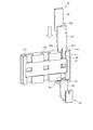
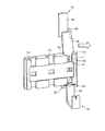
図2は、本実施形態に係る電動モータの周辺を示す斜視図である。図2に示すように、ECU2は、電動モータ6の端面に取り付けられている。ECU2は、第1基板21と、第2基板22と、第3基板23と、ヒートシンク24と、を備える。
FIG. 2 is a perspective view showing the periphery of the electric motor according to the present embodiment. As shown in FIG. 2, the
第1基板21は、プリント基板であり、マイクロコントロールユニットすなわちMCU(Micro Controller Unit)等の電子部品を表面に備える。第2基板22は、コイルおよびコンデンサ等のディスクリート部品が樹脂等でインサート成形されたインサート成形板である。第3基板23は、例えばアルミニウム合金等の金属で形成された基板であり、電界効果トランジスタすなわちFET(Field Effect Transistor)等の電子部品を表面に備える。ヒートシンク24は、例えばアルミニウム合金等の金属で形成された筐体である。
The
ECU2は、ヒートシンク24を介して電動モータ6に取り付けられている。例えば、ヒートシンク24は、ボルト等の締結部材によって電動モータ6に固定されている。第3基板23は、ヒートシンク24に接して固定されている。第2基板22は、第3基板23に対して隙間を空けて配置されており、第3基板23に立てられた支持部材等により支持されている。第1基板21は、第2基板22に対して隙間を空けて配置されており、第3基板23に立てられた支持部材等により支持されている。このように、電動モータ6に近い方から、ヒートシンク24、第3基板23、第2基板22、第1基板21の順に積層されている。
The
第1基板21は、制御信号を生成し第3基板23に入力する。第2基板22は、ECU2の外部からのノイズおよびECU2の内部で生じるノイズを吸収する。第3基板23は、第1基板21からの制御信号に応じて、第2基板22を介して電動モータ6に3相の交流電源を供給し、電動モータ6を駆動する。また、第3基板23がヒートシンク24に接していることにより、第3基板23で生じる熱はヒートシンク24を介して放熱される。
The
図2に示すように、本実施形態に係る電動モータ6は、端子接続構造1によってECU2と電気的に接続されている。端子接続構造1は、3つの第1端子3(第1端子3a、第1端子3bおよび第1端子3c)と、3つの第2端子4(第2端子4a、第2端子4bおよび第2端子4c)と、モータ側筐体10と、端子ガイド11と、を備える。
As shown in FIG. 2, the
モータ側筐体10は、3つの第1端子3と一体にインサート成形された部材であり、電動モータ6の端面に取り付けられている。モータ側筐体10は、3つの第1端子3が電動モータ6とは反対側に露出するように、3つの第1端子3を支持している。端子ガイド11は、樹脂等で形成された部材であって、3つの第1端子3に対向するようにモータ側筐体10に取り付けられている。端子ガイド11は、3つの第2端子4を第1端子3に向けて案内する。
The motor-
以下の端子接続構造1に関する説明において、電動モータ6の回転軸Aに平行な方向は高さ方向と記載される。高さ方向は、図2に示すZ方向である。端子接続構造1から見て、高さ方向に沿ったECU2側は上側と記載され、高さ方向に沿った電動モータ6側は下側と記載される。電動モータ6の径方向外側は奥行き方向と記載される。奥行き方向は、図2に示すY方向である。端子接続構造1から見て、奥行き方向に沿ったECU2の外部側は正面側と記載され、奥行き方向に沿ったECU2の内部側は背面側と記載される。電動モータ6の外周面に対する接線方向に等しい方向は幅方向と記載される。幅方向は、図に示すX方向である。
In the following description of the
なお、高さ方向、奥行き方向および幅方向は、便宜上、上記のように電動モータ6を用いて規定されているが、必ずしも電動モータ6を基準にして決まるわけではない。すなわち、XYZ座標系において、高さ方向がZ方向であり、奥行き方向がY方向であり、幅方向がX方向であればよい。
The height direction, the depth direction, and the width direction are defined using the
図3は、本実施形態に係る端子接続構造の一部を示す斜視図である。図4は、本実施形態に係る第2端子の斜視図である。図5は、本実施形態に係る第1端子の斜視図である。なお、図3においては、第1端子3aおよび第2端子4aが代表して示されており、第1端子3b、第1端子3c、第2端子4bおよび第2端子4cは省略されている。
FIG. 3 is a perspective view showing a part of the terminal connection structure according to the present embodiment. FIG. 4 is a perspective view of the second terminal according to the present embodiment. FIG. 5 is a perspective view of the first terminal according to the present embodiment. In FIG. 3, the
図3に示すように、端子ガイド11は、樹脂等で形成された板状部材であって、ガイド孔11aと、ガイド孔11bと、ガイド孔11cと、カバー12と、を備える。ガイド孔11a、ガイド孔11bおよびガイド孔11cは、端子ガイド11の一方の端面から反対側の端面に向かって貫通する矩形の貫通孔であって、等間隔に並べて配置されている。また、端子ガイド11は、ガイド孔11a、ガイド孔11bおよびガイド孔11cのそれぞれに沿うスリット11sa、スリット11sbおよびスリット11scを正面側に備える。これにより、ガイド孔11a、ガイド孔11bおよびガイド孔11cの内部が、端子ガイド11の正面側に露出している。
As shown in FIG. 3, the
カバー12は、樹脂等で形成された板状部材であって、端子ガイド11の正面側に配置されている。カバー12は、スリット11sa、スリット11sbおよびスリット11scの一部を塞いでいる。また、カバー12は、3つの第1窓12a、第1窓12bおよび第1窓12cを備える。第1窓12a、第1窓12bおよび第1窓12cは、例えば矩形の開口部である。3つの第1窓12a、第1窓12bおよび第1窓12cによって、ガイド孔11a、ガイド孔11bおよびガイド孔11cの内部が正面側に露出している。
The
図4に示すように、第2端子4は、銅等の金属で形成された導電体であって、基部41と、挟持部42と、ブリッジ部43と、連結部44と、を備える。基部41は、板状部材であって、例えば正面側から見て高さ方向に長辺を有する長方形である。挟持部42は、板状部材であって、基部41の一端から下側に突出している。1つの基部41に対して、挟持部42が2つ設けられている。一対の挟持部42は、互いに平行であり、且つスリット425を介して対向している。挟持部42は、正面側から見て略U字状であるU型端子である。挟持部42は、先端に向かってスリット425の幅が広がるように傾斜する面取り部423を、先端の内側に備える。また、基部41と挟持部42との間には、テーパー部411が設けられている。テーパー部411は、基部41から挟持部42に向かって幅方向の長さが小さくなっている。ブリッジ部43は、基部41に対して直交する板状部材であって、基部41の他端から背面側に突出している。連結部44は、基部41に平行且つブリッジ部43に対して直交する板状部材であって、ブリッジ部43の基部41とは反対側の端部から上側に突出している。例えば基部41、ブリッジ部43および連結部44を高さ方向から見ると、略U字状である。このため、第2端子4の細長比は、ブリッジ部43を備えない場合(第2端子4全体が高さ方向からみて直線状である場合)に比較して小さくなる。したがって、第2端子4は座屈しにくい。また、連結部44は、図2に示すように第2基板22を貫通しており、且つ第2基板22に配置された端子と例えばTIG(Tungsten Inert Gas)溶接によって接合されることで電気的に接続されている。また、基部41の上側の端面およびブリッジ部43の上側の端面は、第2基板22の下側の表面(第3基板23に対向する表面)に接している。このため、基部41、挟持部42またはブリッジ部43に加わった外力は、基部41およびブリッジ部43を介して第2基板22に受けとめられる。したがって、連結部44と第2基板22の端子との接合部への荷重の伝達が抑制される。
As shown in FIG. 4, the
なお、第2端子4を用いて説明すると、幅方向は、基部41の表面に平行且つ挟持部42の突出方向に対して直交する方向と言い換えることができる。高さ方向は、挟持部42の突出方向と言い換えることができる。
When described using the
図5に示すように、第1端子3は、銅等の金属で形成された導電体であって、基部31と、被挟持部32と、連結部33と、を備える。基部31は、高さ方向から見て矩形の環状部材である。被挟持部32は、矩形断面の棒状部材であって、基部31の正面側の一辺から背面側の一辺に亘って設けられている。被挟持部32は、高さ方向から見て略I字状であるI型端子である。連結部33は、基部31から下側に突出する部材であって、幅方向から見て略U字状である。連結部33は、電動モータ6側の端子と電気的に接続された状態で、図2に示したモータ側筐体10に埋め込まれている。連結部33は、電動モータ6の内部から引き出された端子と、例えばTIG溶接によって接合されることで電気的に接続されている。
As shown in FIG. 5, the
なお、第1端子3の連結部33は、必ずしも図3に示すように正面側に向かって屈曲していなくてもよい。例えば、後述する図14に示すように、連結部33は背面側に向かって屈曲していてもよい。また、連結部33の形状は、図3に示す形状に限られず、電動モータ6の内部から引き出された端子と接合しやすく且つインサート成形に適した形状であればよい。
In addition, the
図4に示す基部41の幅方向の長さL2は、図3に示すガイド孔11a、ガイド孔11bおよびガイド孔11cの幅方向の長さL1に略等しい。図4に示す一対の挟持部42の幅方向の長さL3は、図3に示すガイド孔11a、ガイド孔11bおよびガイド孔11cの幅方向の長さL1よりも小さい。また、図4に示すスリット425の幅方向の最小長さL4は、図5に示す被挟持部32の幅方向の長さL6より小さい。図4に示すスリット425の幅方向の最大長さL5は、図5に示す被挟持部32の幅方向の長さL6よりも大きい。
The length L2 in the width direction of the base 41 shown in FIG. 4 is substantially equal to the length L1 in the width direction of the
図3に示すように、第1端子3aの被挟持部32がガイド孔11aの一端に配置されている。また、ガイド孔11aの他端から第2端子4aの挟持部42および基部41が挿入されている。挟持部42の先端は第1端子3aの基部31を貫通しており、被挟持部32が挟持部32に挟まれている。上述したようにスリット425の最小長さL4が被挟持部32の長さL6より小さいので、被挟持部32と挟持部32との接触が保たれる。このため、第1端子3aおよび第2端子4aが導通している。
As shown in FIG. 3, the sandwiched
図6は、第1端子および第2端子が接続される前における端子接続構造の周辺を示す斜視図である。図7は、第2端子がガイド孔に挿入される時の端子接続構造の周辺を示す斜視図である。図8〜図11は、第2端子がガイド孔に挿入される時の第2端子の挙動を説明する説明図である。図12は、第2端子がガイド孔に挿入される時の端子接続構造の周辺を拡大して示す斜視図である。なお、図8〜図11においては、第1端子3aおよび第2端子4aが代表して示されており、第1端子3b、第1端子3c、第2端子4bおよび第2端子4cは省略されている。
FIG. 6 is a perspective view showing the periphery of the terminal connection structure before the first terminal and the second terminal are connected. FIG. 7 is a perspective view showing the periphery of the terminal connection structure when the second terminal is inserted into the guide hole. 8-11 is explanatory drawing explaining the behavior of a 2nd terminal when a 2nd terminal is inserted in a guide hole. FIG. 12 is an enlarged perspective view showing the periphery of the terminal connection structure when the second terminal is inserted into the guide hole. 8 to 11, the
図6に示すように、電動モータ6およびECU2を接続する際、3つの第2端子4a、第2端子4bおよび第2端子4cが、それぞれガイド孔11a、ガイド孔11bおよびガイド孔11cに対向して配置される。そして、ECU2が電動モータ6に向かってスライドさせられる。このため、図7に示すように、第2端子4a、第2端子4bおよび第2端子4cがそれぞれガイド孔11a、ガイド孔11bおよびガイド孔11cに挿入される。
As shown in FIG. 6, when the
上述したように、挟持部42の長さL3(図4参照)がガイド孔11aの長さL1(図3参照)よりも小さい。このため、ガイド孔11aに対する第2端子4aの位置が幅方向にずれていても、図8に示すように挟持部42はガイド孔11aに進入できる。
As described above, the length L3 (see FIG. 4) of the clamping
挟持部42がさらにガイド孔11aに進入すると、テーパー部411がガイド孔11aに挿入される。上述したように、基部41の長さL4(図4参照)がガイド孔11aの長さL1(図3参照)に略等しい。このため、ガイド孔11aに対する第2端子4aの位置が幅方向にずれている場合、図9に示すようにテーパー部411がガイド孔11aの縁に接触する。
When the clamping
テーパー部411がさらにガイド孔11aに進入すると、第2端子4aはガイド孔11aの縁から幅方向の反力を受ける。このため、基部41および挟持部42は、図10に示すようにガイド孔11aに対して傾く。一方、連結部44が貫通する第2基板22の孔の内壁によって、連結部44の傾きが規制されている。このため、基部41と連結部44との間にあるブリッジ部43が捩られる。より具体的には、ブリッジ部43は、基部41側の端部が正面側から見て左周りに捩られる。ブリッジ部43は、基部41に対して直交する板状部材であるため、容易に変形することができる。
When the tapered
第2端子4aがさらに第1端子3aに向かって押し込まれると、図11に示すように、ブリッジ部43が変形しながら第2端子4aがガイド孔11a内を進入していく。そして、基部41がガイド孔11aに進入すると、第2端子4aの傾きが矯正される。すなわち、挟持部42および基部41が真っ直ぐにガイド孔11aに挿入された状態が保たれる。その後、後述する仮止め機構5によって、挟持部42の高さ方向の移動が規制される。最終的に、ECU2が下側にプレスされる(加圧される)ことで第1端子3と第2端子4とが接続される。すなわち、第1端子3の被挟持部32および第2端子4の挟持部42により電気的接点が形成される。ECU2がプレスされる前に第2端子4aの傾きが矯正されているので、挟持部42は、被挟持部32を両側から均等に挟むことができる。また、上述したように基部41の上側の端面およびブリッジ部43の上側の端面が第2基板22の下側の表面に接しているので、ECU2が下側にプレスされる時に連結部44と第2基板22の端子との接合部への荷重の伝達が抑制される。
When the
また、ECU2が電動モータ6に向かって押し込まれると、図12に示すように、端子ガイド11の凸部111が、ヒートシンク24の凹部245に嵌合する。凸部111は、端子ガイド11の側面に高さ方向に沿って設けられた突出部である。凹部245は、ヒートシンク24のうち凸部111に対応する位置に高さ方向に沿って設けられた溝である。これにより、凸部111がヒートシンク24を高さ方向に案内する。このため、第2端子4a、第2端子4bおよび第2端子4cは、ガイド孔11a、ガイド孔11bおよびガイド孔11cに対して容易に真っ直ぐ進入することができる。
When the
図13は、第2端子がガイド孔の一端に到達した時の端子接続構造の周辺を示す斜視図である。図14は、図13において、モータ側筐体を省略して第1端子を露出させた図である。図15は、第2端子がガイド孔の一端に到達した時の仮止め機構を示す断面図である。図16は、図13において第1端子の周辺を拡大した拡大図である。図13に示すように仮止め機構5を備える。仮止め機構5は、例えばモータ側筐体10およびヒートシンク24である。
FIG. 13 is a perspective view showing the periphery of the terminal connection structure when the second terminal reaches one end of the guide hole. FIG. 14 is a view in which the first terminal is exposed in FIG. 13 by omitting the motor-side casing. FIG. 15 is a cross-sectional view showing the temporary fixing mechanism when the second terminal reaches one end of the guide hole. FIG. 16 is an enlarged view in which the periphery of the first terminal in FIG. 13 is enlarged. As shown in FIG. 13, a
図13および図14に示すように、モータ側筐体10は、ヒートシンク24対して幅方向に対向する2つのアーム13を備える。アーム13は、モータ側筐体10の幅方向の両端から上側に向かって設けられている。図15に示すように、アーム13は、幅方向に突出する突出部131を先端に備える。突出部131の上側表面である上面132は、ヒートシンク24に近い部分ほど下側に傾斜している。突出部131の下側表面である下面133は、高さ方向に対して直交する面である。
As shown in FIGS. 13 and 14, the motor-
また、図13および図14に示すように、ヒートシンク24は嵌合溝241および嵌合溝242を備える。嵌合溝241は矩形の溝である。嵌合溝242は、嵌合溝241よりも下側に配置された矩形の溝であって、下側の端部が開口している。
As shown in FIGS. 13 and 14, the
ECU2が電動モータ6に向かって押し込まれると、アーム13の突出部131が、嵌合溝242の下側の端部から嵌合溝242内に進入する。そして、挟持部42の先端がガイド孔11a、ガイド孔11bおよびガイド孔11cの一端(下側の端部)に到達した時、突出部131の上面132が嵌合溝242の縁に接触する。これにより、ヒートシンク24の移動が規制されるので、挟持部42が高さ方向に位置決めされる。このとき、図16に示すように、挟持部42は被挟持部32に接触していない。より具体的には、面取り部423が、被挟持部32に対して隙間を空けて対向している。このように、アーム13および嵌合溝242によって、第1端子3および第2端子4が接続される直前で、挟持部42の高さ方向の位置が仮決めされる。これにより、被挟持部32に対する挟持部42の位置調整の要否の判断が容易になる。この時点でも被挟持部32に対する挟持部42の位置がずれている場合、ECU2または電動モータ6が幅方向にプレスされる(加圧される)ことで、ブリッジ部43が強制的に変形させられる。これにより、被挟持部32に対する挟持部42の位置の精度がさらに向上する。
When the
図17は、第1端子および第2端子が接続された時の端子接続構造の周辺を示す斜視図である。図18は、第1端子および第2端子が接続された時の仮止め機構を示す断面図である。 FIG. 17 is a perspective view showing the periphery of the terminal connection structure when the first terminal and the second terminal are connected. FIG. 18 is a cross-sectional view showing the temporary fixing mechanism when the first terminal and the second terminal are connected.
図13および図14に示した状態の後、ECU2が下側にプレスされる(加圧される)。これにより、図18に示すように、アーム13の突出部131が弾性変形し、嵌合溝242の縁を乗り越える。そして、突出部131は嵌合溝241に嵌合する。すなわち、ECU2は、スナップフィットにより電動モータ6に固定される。突出部131の下面133が嵌合溝241の縁に引っ掛かるので、アーム13の下側への移動は規制される。すなわち、ECU2および電動モータ6の位置関係が固定される。このとき、図3に示すように、挟持部42は被挟持部32に接触している。これにより、第1端子3と第2端子4との通電状態が保たれる。
After the state shown in FIGS. 13 and 14, the
図19は、本実施形態に係る端子接続構造の周辺を拡大して示す側面図である。図20は、本実施形態に係る端子接続構造の周辺を拡大して示す斜視図である。図19および図20は、第1端子3と第2端子4とが接触している状態、すなわち図17に示す状態を示している。
FIG. 19 is an enlarged side view showing the periphery of the terminal connection structure according to this embodiment. FIG. 20 is an enlarged perspective view showing the periphery of the terminal connection structure according to this embodiment. 19 and 20 show a state where the
図19に示すように、スリット11sa、スリット11sbおよびスリット11sc並びに第1窓12a、第1窓12bおよび第1窓12cを介して、挟持部42の根本側端部426が露出している。これにより、挟持部42の高さ方向の位置を確認することが容易になる。
As shown in FIG. 19, the root
図20に示すように、第2窓11e、第2窓11fおよび第2窓11gを介して、挟持部42と被挟持部32との接続部分が露出している。第2窓11e、第2窓11fおよび第2窓11gは、それぞれスリット11sa、スリット11sbおよびスリット11scの一部である。これにより、挟持部42と被挟持部32との接続を確認することが容易になる。
As shown in FIG. 20, the connection part of the clamping
なお、第2端子4において、ブリッジ部43は、必ずしも基部41に対して直交する板状でなくてもよく、基部41と交差する板状であればよい。また、基部41、ブリッジ部43および連結部44を高さ方向から見た形状は、必ずしも略U字状でなくてもよい。第2端子4の座屈を抑制するためには、ブリッジ部43を備えない場合に比較して第2端子4の細長比が小さければよい。また、テーパー部411の位置は、必ずしも基部41と挟持部42との間でなくてもよい。例えば、テーパー部411は、基部41の側面(幅方向に対して直交する面)に設けられていてもよい(図4で示す位置よりも上側に配置されてもよい)。または、テーパー部411は、挟持部42の側面に設けられていてもよい(図4で示す位置よりも下側に配置されてもよい)。
In the
なお、カバー12はなくてもよい。このような場合、スリット11sa、スリット11sbおよびスリット11scによって、挟持部42の根本側端部426および挟持部42と被挟持部32との接続部分の両方が露出する。また、スリット11sa、スリット11sbおよびスリット11scがない場合、第1窓12a、第1窓12bおよび第1窓12cは、端子ガイド11の正面側の表面に空けられた開口部として設けられればよい。
The
以上で説明したように、本実施形態に係る電動パワーステアリング装置8は、端子接続構造1は、第1端子3と、第2端子4と、端子ガイド11と、を備える。第1端子3は、被挟持部32を備える。第2端子4は、板状の基部41と、基部41の一端から突出し被挟持部32を両側から挟む一対の挟持部42と、基部41の他端から基部41に対して交差する方向に突出する板状のブリッジ部43と、を備える。端子ガイド11は、一端に第1端子3が配置され且つ他端から第2端子4が挿入されるガイド孔11a(ガイド孔11bまたはガイド孔11c)を備える。
As described above, in the electric
第2端子4がガイド孔11a(ガイド孔11bまたはガイド孔11c)に挿入される際、ガイド孔11aに対する第2端子4の位置が幅方向にずれていると、第2端子4にはガイド孔11aから反力が加わる。このとき、ブリッジ部43は、基部41に対して直交する板状部材であるため、容易に変形することができる。ブリッジ部43が変形することで、挟持部42の姿勢がガイド孔11a(ガイド孔11bまたはガイド孔11c)に沿うように矯正される。このため、第2端子4の第1端子3との接触部分の面積および接触部分に加わる圧力が所定の大きさに保たれる。よって、本実施形態に係る端子接続構造1は、第1端子3と第2端子4との接触抵抗の増大を抑制できる。
When the
また、端子接続構造1において、第2端子4は、基部41と挟持部42との間に、基部41の表面に平行且つ挟持部42の突出方向に対して直交する方向である幅方向の長さが挟持部42の先端に向かって小さくなるテーパー部411を備える。これにより、ガイド孔11aから反力を受ける位置が、ブリッジ部43から遠く且つ挟持部42に重ならない位置となる。このため、ガイド孔11aから反力が、ブリッジ部43からテーパー部411までの距離に応じた曲げモーメントとしてブリッジ部43に作用し、且つ挟持部43の変形させる力として消費されにくい。よって、ガイド孔11aからの反力がブリッジ部43を変形させる力として効率的に伝わるため、ブリッジ部43がより容易に変形できる。
In the
また、端子接続構造1は、第2端子4が第1端子3に接続される前に、挟持部42の先端をガイド孔11a(ガイド孔11bまたはガイド孔11c)の一端に位置決めする仮止め機構5を備える。これにより、仮止め機構5によって、第1端子3および第2端子が接続される直前で、挟持部42の高さ方向の位置が仮決めされる。このため、被挟持部32に対する挟持部42の位置調整の要否の判断が容易になる。
In addition, the
また、端子接続構造1において、一対の挟持部42の根本側端部426を露出させる第1窓12a(第1窓12bまたは第1窓12c)を備える。これにより、挟持部42の高さ方向の位置を確認することが容易になる。
Further, the
また、端子接続構造1において、挟持部42と被挟持部32との接続部分を露出させる第2窓11e(第2窓11fまたは第2窓11g)を備える。これにより、挟持部42と被挟持部32との接続を確認することが容易になる。
Further, the
1 端子接続構造
10 モータ側筐体
11 端子ガイド
111 凸部
11a、11b、11c ガイド孔
11e、11f、11g 第2窓
11sa、11sb、11sc スリット
12 カバー
12a、12b、12c 第1窓
13 アーム
131 突出部
132 上面
133 下面
2 ECU(電子制御装置)
21 第1基板
22 第2基板
23 第3基板
24 ヒートシンク
241、242 嵌合溝
245 凹部
3、3a、3b、3c 第1端子
31 基部
32 被挟持部
33 連結部
4、4a、4b、4c 第2端子
41 基部
411 テーパー部
42 挟持部
423 面取り部
425 スリット
426 根本側端部
43 ブリッジ部
44 連結部
5 仮止め機構
6 電動モータ
71 トルクセンサ
72 減速装置
73 車速センサ
74 イグニッションスイッチ
8 電動パワーステアリング装置
81 ステアリングホイール
82 ステアリングシャフト
82a 入力軸
82b 出力軸
83 アクチュエータ
84 ユニバーサルジョイント
85 ロアシャフト
86 ユニバーサルジョイント
87 ピニオンシャフト
88 ステアリングギヤ
88a ピニオン
88b ラック
89 タイロッド
9 車両
DESCRIPTION OF
21 1st board |
Claims (8)
板状の基部と、前記基部の一端から突出し前記被挟持部を両側から挟む一対の挟持部と、前記基部の他端から前記基部に対して交差する方向に突出する板状のブリッジ部と、を備える第2端子と、
一端に前記第1端子が配置され且つ他端から前記第2端子が挿入されるガイド孔を備える端子ガイドと、
を備え、
前記端子ガイドは、前記基部に対して直交する方向で前記基部及び前記挟持部に重なるカバーを備え、
前記カバーは、前記一対の挟持部の根本側端部を露出させる第1窓を備える
端子接続構造。 A first terminal having a sandwiched portion;
A plate-like base portion, a pair of sandwiching portions projecting from one end of the base portion and sandwiching the sandwiched portion from both sides, a plate-like bridge portion projecting in a direction intersecting the base portion from the other end of the base portion, A second terminal comprising:
A terminal guide including a guide hole in which the first terminal is disposed at one end and the second terminal is inserted from the other end;
Equipped with a,
The terminal guide includes a cover that overlaps the base and the clamping part in a direction orthogonal to the base,
The cover has a terminal connection structure including a first window exposing a base side end portion of the pair of sandwiching portions .
板状の基部と、前記基部の一端から突出し前記被挟持部を両側から挟む一対の挟持部と、前記基部の他端から前記基部に対して交差する方向に突出する板状のブリッジ部と、を備える第2端子と、
一端に前記第1端子が配置され且つ他端から前記第2端子が挿入されるガイド孔を備える端子ガイドと、
を備え、
前記端子ガイドは、前記基部に対して直交する方向で前記挟持部に重なっており、前記挟持部と前記被挟持部との接続部分を露出させる第2窓を備える端子接続構造。 A first terminal having a sandwiched portion;
A plate-like base portion, a pair of sandwiching portions projecting from one end of the base portion and sandwiching the sandwiched portion from both sides, a plate-like bridge portion projecting in a direction intersecting the base portion from the other end of the base portion, A second terminal comprising:
A terminal guide including a guide hole in which the first terminal is disposed at one end and the second terminal is inserted from the other end;
Equipped with a,
The terminal connection structure includes a second window that overlaps with the clamping part in a direction orthogonal to the base part and exposes a connection part between the clamping part and the clamped part .
Priority Applications (5)
| Application Number | Priority Date | Filing Date | Title |
|---|---|---|---|
| JP2015024607A JP6107847B2 (en) | 2015-02-10 | 2015-02-10 | Terminal connection structure, motor, actuator, electric power steering device and vehicle |
| CN201680005414.0A CN107112692B (en) | 2015-02-10 | 2016-01-20 | Terminal bindiny mechanism, motor, actuator, electric power steering device and vehicle |
| US15/540,778 US9929525B2 (en) | 2015-02-10 | 2016-01-20 | Terminal connection structure for electricpower steering system of a vehicle |
| PCT/JP2016/051588 WO2016129347A1 (en) | 2015-02-10 | 2016-01-20 | Terminal connection structure, motor, actuator, electric power steering device, and vehicle |
| EP16748992.1A EP3223375B1 (en) | 2015-02-10 | 2016-01-20 | Terminal connection structure, motor, actuator, electric power steering device, and vehicle |
Applications Claiming Priority (1)
| Application Number | Priority Date | Filing Date | Title |
|---|---|---|---|
| JP2015024607A JP6107847B2 (en) | 2015-02-10 | 2015-02-10 | Terminal connection structure, motor, actuator, electric power steering device and vehicle |
Publications (3)
| Publication Number | Publication Date |
|---|---|
| JP2016149216A JP2016149216A (en) | 2016-08-18 |
| JP2016149216A5 JP2016149216A5 (en) | 2017-02-09 |
| JP6107847B2 true JP6107847B2 (en) | 2017-04-05 |
Family
ID=56615435
Family Applications (1)
| Application Number | Title | Priority Date | Filing Date |
|---|---|---|---|
| JP2015024607A Expired - Fee Related JP6107847B2 (en) | 2015-02-10 | 2015-02-10 | Terminal connection structure, motor, actuator, electric power steering device and vehicle |
Country Status (5)
| Country | Link |
|---|---|
| US (1) | US9929525B2 (en) |
| EP (1) | EP3223375B1 (en) |
| JP (1) | JP6107847B2 (en) |
| CN (1) | CN107112692B (en) |
| WO (1) | WO2016129347A1 (en) |
Families Citing this family (8)
| Publication number | Priority date | Publication date | Assignee | Title |
|---|---|---|---|---|
| JP6433420B2 (en) * | 2015-12-25 | 2018-12-05 | 本田技研工業株式会社 | Torque sensor terminal block structure |
| EP3477776B1 (en) * | 2016-08-23 | 2021-07-14 | NSK Ltd. | Terminal connection component, and terminal connection structure using same for connecting control device and motor |
| KR101892895B1 (en) | 2018-03-07 | 2018-10-04 | (주)에이테크오토모티브 | Terminal structure of EPB actuator gear box |
| JP1626561S (en) * | 2018-04-26 | 2019-03-18 | Motor with controller for power steering | |
| DE102018216484B4 (en) | 2018-09-26 | 2022-02-17 | Robert Bosch Gmbh | Steering device with a connector unit for electrically contacting a steering sensor unit |
| JP7403308B2 (en) * | 2019-12-16 | 2023-12-22 | ミネベアミツミ株式会社 | motor |
| JP7267214B2 (en) * | 2020-01-21 | 2023-05-01 | ヒロセ電機株式会社 | cable connector |
| KR102540340B1 (en) * | 2021-04-23 | 2023-06-08 | 계양전기 주식회사 | Terminal Connection Structure Of Electric Actuator |
Family Cites Families (14)
| Publication number | Priority date | Publication date | Assignee | Title |
|---|---|---|---|---|
| AR208483A1 (en) * | 1975-11-10 | 1976-12-27 | Amp Inc | ELECTRICAL TERMINAL |
| JPS59115692U (en) * | 1983-01-21 | 1984-08-04 | 富士通電装株式会社 | Guide structure for plug connection |
| US5178558A (en) * | 1991-09-23 | 1993-01-12 | Minnesota Mining And Manufacturing Company | Cross connect system for telecommunications systems |
| US5281163A (en) * | 1991-09-23 | 1994-01-25 | Minnesota Mining And Manufacturing Company | Cross connect system for telecommunications systems |
| US6045392A (en) * | 1998-06-30 | 2000-04-04 | Lucent Technologies Inc. | Modified index strip with integrated push cap for wire termination |
| US6716054B1 (en) * | 2002-12-16 | 2004-04-06 | Tyco Electronics Corporation | Plug and block connector system for differential contact pairs |
| US7223115B2 (en) * | 2005-06-03 | 2007-05-29 | Commscope, Inc. Of North Carolina | Cross-connect systems with connector blocks having balanced insulation displacement contacts |
| US7273398B2 (en) * | 2005-11-01 | 2007-09-25 | Tyco Electronics Corporation | Electrical device carrier contact assembly |
| DE102006052119A1 (en) | 2006-11-06 | 2008-05-08 | Robert Bosch Gmbh | Cutting-clamp connection, as well as method for connecting two components |
| DE102007026094B4 (en) * | 2007-06-05 | 2023-05-11 | Tyco Electronics Services Gmbh | Contact element for a connector for printed circuit boards |
| WO2013038572A1 (en) * | 2011-09-12 | 2013-03-21 | 三菱電機株式会社 | Electric drive device |
| JP5827157B2 (en) * | 2012-03-21 | 2015-12-02 | 日立オートモティブシステムズ株式会社 | Electric actuator terminal connection structure |
| JP5802158B2 (en) * | 2012-03-21 | 2015-10-28 | 日立オートモティブシステムズ株式会社 | Electric actuator |
| US9444311B2 (en) | 2012-08-28 | 2016-09-13 | Mitsubishi Electric Corporation | Electric driving device and method for manufacturing electric driving device |
-
2015
- 2015-02-10 JP JP2015024607A patent/JP6107847B2/en not_active Expired - Fee Related
-
2016
- 2016-01-20 WO PCT/JP2016/051588 patent/WO2016129347A1/en active Application Filing
- 2016-01-20 US US15/540,778 patent/US9929525B2/en not_active Expired - Fee Related
- 2016-01-20 EP EP16748992.1A patent/EP3223375B1/en active Active
- 2016-01-20 CN CN201680005414.0A patent/CN107112692B/en not_active Expired - Fee Related
Also Published As
| Publication number | Publication date |
|---|---|
| EP3223375A4 (en) | 2018-02-21 |
| JP2016149216A (en) | 2016-08-18 |
| EP3223375A1 (en) | 2017-09-27 |
| US9929525B2 (en) | 2018-03-27 |
| CN107112692A (en) | 2017-08-29 |
| CN107112692B (en) | 2018-09-11 |
| US20170373451A1 (en) | 2017-12-28 |
| WO2016129347A1 (en) | 2016-08-18 |
| EP3223375B1 (en) | 2019-03-13 |
Similar Documents
| Publication | Publication Date | Title |
|---|---|---|
| JP6107847B2 (en) | Terminal connection structure, motor, actuator, electric power steering device and vehicle | |
| JP5067159B2 (en) | Electric power steering device | |
| US8102138B2 (en) | Electric power steering apparatus and method of assembling the same | |
| CN109478731B (en) | Terminal connecting member, and terminal connecting structure between control device and motor using the same | |
| JP6038383B2 (en) | Motor drive device | |
| JP2008079465A (en) | Brushless motor | |
| CN108093665B (en) | Brushless motor, and electric power steering device and vehicle having the same | |
| CN105720748B (en) | Drive device | |
| WO2016035755A1 (en) | Connecting part for electric motor and electic motor control device, connecting structure for electric motor and electric motor control device using this connecting part, and electric power steering device, electric actuator, and vehicle using this connecting structure | |
| JP2019080468A (en) | Electrically-driven driving device and electrically-driven power steering device | |
| JP2008290614A (en) | Electric power steering device | |
| JP2012218701A (en) | Electric power steering device | |
| EP2977736B1 (en) | Torque detection device, electric power steering device, and vehicle | |
| JP2010111248A (en) | Electric power steering device | |
| JP7041546B2 (en) | Electronic control device and electric drive device | |
| JP5304710B2 (en) | Electric power steering apparatus and assembly method thereof | |
| JP2012201294A (en) | Electric power steering device and assembling method thereof | |
| JP6048631B1 (en) | Torque detection device, electric power steering device, and vehicle | |
| JP2013017259A (en) | Structure for terminal connection of motor and apparatus, motor, and electric power steering system | |
| JP5299344B2 (en) | Electric power steering device | |
| JP2011245977A (en) | Electric power steering apparatus | |
| JP2015227161A (en) | Electric power steering device | |
| JP2015082891A (en) | Brushless motor and electric power steering device | |
| JP2017169261A (en) | Connection structure of electric motor and board housed in controller thereof | |
| JP2015195214A (en) | Structure for terminal connection of motor and apparatus, motor, electric power steering device, vehicle, and industrial machinery |
Legal Events
| Date | Code | Title | Description |
|---|---|---|---|
| A521 | Request for written amendment filed |
Free format text: JAPANESE INTERMEDIATE CODE: A523 Effective date: 20161226 |
|
| A621 | Written request for application examination |
Free format text: JAPANESE INTERMEDIATE CODE: A621 Effective date: 20161226 |
|
| A871 | Explanation of circumstances concerning accelerated examination |
Free format text: JAPANESE INTERMEDIATE CODE: A871 Effective date: 20161226 |
|
| TRDD | Decision of grant or rejection written | ||
| A975 | Report on accelerated examination |
Free format text: JAPANESE INTERMEDIATE CODE: A971005 Effective date: 20170130 |
|
| A01 | Written decision to grant a patent or to grant a registration (utility model) |
Free format text: JAPANESE INTERMEDIATE CODE: A01 Effective date: 20170207 |
|
| A61 | First payment of annual fees (during grant procedure) |
Free format text: JAPANESE INTERMEDIATE CODE: A61 Effective date: 20170220 |
|
| R150 | Certificate of patent or registration of utility model |
Ref document number: 6107847 Country of ref document: JP Free format text: JAPANESE INTERMEDIATE CODE: R150 |
|
| LAPS | Cancellation because of no payment of annual fees |