JP2009243715A - Leakage detecting tube and heat exchanger - Google Patents
Leakage detecting tube and heat exchanger Download PDFInfo
- Publication number
- JP2009243715A JP2009243715A JP2008088090A JP2008088090A JP2009243715A JP 2009243715 A JP2009243715 A JP 2009243715A JP 2008088090 A JP2008088090 A JP 2008088090A JP 2008088090 A JP2008088090 A JP 2008088090A JP 2009243715 A JP2009243715 A JP 2009243715A
- Authority
- JP
- Japan
- Prior art keywords
- tube
- pipe
- leak detection
- outer tube
- uneven portion
- Prior art date
- Legal status (The legal status is an assumption and is not a legal conclusion. Google has not performed a legal analysis and makes no representation as to the accuracy of the status listed.)
- Pending
Links
Images


Abstract
Description
本発明は、水と冷媒とを熱媒体として用いて構成される熱交換器において当該水および冷媒の漏洩を検知するために用いられる漏洩検知管と、この漏洩検知管を備えた熱交換器に関する。 The present invention relates to a leak detection tube used for detecting leakage of water and refrigerant in a heat exchanger configured using water and refrigerant as a heat medium, and a heat exchanger provided with the leak detection tube. .
一般に、熱交換器の構成として、大径管と、その大径管の内部に漏洩検知管としての小径管を備える構成のものが知られている。例えば、給湯器用の熱交換器においては、一般的に、大径管の内側に第1熱媒体(例えば、水)を流し、小径管(漏洩検知管、伝熱管)の内側に第2熱媒体(例えば、二酸化炭素や代替フロン等の冷媒)を流して、これらの間で熱交換を行っている。 Generally, a heat exchanger having a large-diameter tube and a small-diameter tube as a leak detection tube inside the large-diameter tube is known. For example, in a heat exchanger for a water heater, generally, a first heat medium (for example, water) is allowed to flow inside a large diameter pipe, and a second heat medium is disposed inside a small diameter pipe (leakage detection pipe, heat transfer pipe). (For example, a refrigerant such as carbon dioxide or alternative chlorofluorocarbon) is flowed to exchange heat between them.
このような熱交換器においては、運転効率を高める等の観点から、熱媒体間の熱交換性能を高めることが要求されており、その一例として、大径管に複数本の漏洩検知管(=小径管)を内包させ、大径管の内側にインナー材やバッフル材を配置した構造を有する熱交換器が知られている(例えば、特許文献1参照)。また、別の例として、小径管(=漏洩検知管)を大径管に内包させた構造を有する熱交換器が知られている(例えば、特許文献2参照)。 In such a heat exchanger, it is required to improve the heat exchange performance between the heat media from the viewpoint of increasing the operation efficiency. As an example, a plurality of leak detection tubes (= A heat exchanger having a structure in which a small-diameter pipe is included and an inner material and a baffle material are arranged inside the large-diameter pipe is known (for example, see Patent Document 1). As another example, a heat exchanger having a structure in which a small-diameter pipe (= leakage detection pipe) is included in a large-diameter pipe is known (for example, see Patent Document 2).
この特許文献1に開示された熱交換器は、小径管(漏洩検知管)の配設数を増やすことによって伝熱面積を増加させ、また、インナー材やバッフル材によって大径管を流れる熱媒体に乱流を生じさせることにより、伝熱性能を向上させるものである。また、特許文献2に開示された熱交換器では、コルゲート加工が施された伝熱管の外周に平滑管を嵌合して漏洩検知管を構成し、さらに、漏洩検知管を大径管の内側に配置し、漏洩検知管と大径管との間に冷媒を流し、伝熱管内に水を流す構成となっており、低流速の場合でも優れた熱交換性能が得られるとされている。
しかしながら、特許文献1に開示された熱交換器では、漏洩検知管として平滑管を用いているために伝熱面積を広くすることができず、そのため、大径管の内側にインナー材やバッフル材を設けても、伝熱性能を飛躍的に向上させることは困難である。また、大径管の内部に配置されるインナー材やバッフル材により、大径管を流れる熱媒体の圧力損失が大きくなるという問題も生じる。
However, in the heat exchanger disclosed in
特許文献2に開示された熱交換器では、大径管に冷媒を流す構成としているために、冷媒の熱が大径管を通じて外部へ放熱されてしまい、これによって漏洩検知管(伝熱管)を流れる水への伝熱量が低下し、伝熱性能が低下するという問題がある。また、水への伝熱性能を上げるには、漏洩検知管の外径を大きくしてその表面積を大きくすることが考えられる。しかしながら、その場合、漏洩検知管内部の伝熱管の直径が大きくなり、伝熱管内を流れる水の流束が遅くなってしまうため、伝熱性能の向上にはつながらない。また、漏洩検知管の外面に邪魔板を設ける等の方法により、伝熱性能を向上させることも考えられるが、製造コストの上昇に見合う効果を得ることが難しいという問題がある。
In the heat exchanger disclosed in
本発明はかかる事情に鑑みてなされたものであり、高い熱交換性能を有する漏洩検知管およびこの漏洩検知管を用いた熱交換器を提供することを目的とする。 The present invention has been made in view of such circumstances, and an object thereof is to provide a leak detection tube having high heat exchange performance and a heat exchanger using the leak detection tube.
本発明に係る漏洩検知管において、請求項1に係る漏洩検知管は、内管と、前記内管の外側に嵌合する外管を備え、前記内管の内側または前記外管の外側に流通する水または冷媒の漏洩を、前記内管と前記外管との間に形成される漏洩路を介して検知する漏洩検知管であって、前記外管は、その全長の少なくとも一部の領域に、管周方向に沿って形成された多数の凹部と凸部とからなる外管凹凸部を備え、前記外管凹凸部の前記凹部および前記凸部は前記外管の管軸方向に沿って伸び、前記外管は、前記外管凹凸部の前記凹部の底部の内面が前記内管に当接し、前記漏洩路は、前記内管の外周面と前記外管凹凸部の前記凸部の内面とによって形成されていることを特徴とする。
In the leak detection pipe according to the present invention, the leak detection pipe according to
このような構成によれば、漏洩検知管を構成する外管が外管凹凸部を備えることによって、この外管の外側を流通する水または冷媒が撹拌されると共に、外管の管外表面積が増加する。これによって漏洩検知管の伝熱性能が向上する。 According to such a configuration, the outer tube constituting the leak detection tube includes the outer tube uneven portion, so that water or refrigerant flowing outside the outer tube is agitated and the outer surface area of the outer tube is increased. To increase. This improves the heat transfer performance of the leak detection tube.
請求項2に係る漏洩検知管は、前記外管凹凸部は、管軸直交断面において、前記凹部の凹部深さHS1と前記外管の最大外径OD1との比(HS1/OD1)が0.02〜0.1、前記凹部の数が4〜32であることを特徴とする。
In the leak detection tube according to
このような構成によれば、外管凹凸部の形状が最適化されているため、外管の外側を流通する水または冷媒が一層撹拌されるため、漏洩検知管の伝熱性能がより一層向上する。 According to such a configuration, since the shape of the outer tube uneven portion is optimized, the water or refrigerant flowing outside the outer tube is further stirred, so the heat transfer performance of the leak detection tube is further improved. To do.
請求項3に係る漏洩検知管は、前記外管凹凸部は、管軸方向に沿って、らせん状に形成され、管軸に対する前記凹部のねじれ角γ1が30度以下であることを特徴とする。
The leak detection tube according to
このような構成によれば、外管凹凸部が、らせん状に所定のねじれ角γ1で形成されていることによって、外管の外側を流通する水または冷媒が一層撹拌されて、漏洩検知管の伝熱性能がより一層向上する。また、外管凹凸部をらせん状にすることによって、外管の外側を流通する水または冷媒の圧力損失を小さく抑えることができる。 According to such a configuration, the outer tube uneven portion, by being formed with a predetermined twist angle gamma 1 spirally, water or refrigerant flowing in the outer of the outer tube is further stirred, leak detection tube The heat transfer performance is further improved. In addition, by making the outer tube uneven portion spiral, the pressure loss of water or refrigerant flowing outside the outer tube can be reduced.
請求項4に係る漏洩検知管は、内管と、前記内管の外側に嵌合する外管を備え、前記内管の内側または前記外管の外側に流通する水または冷媒の漏洩を、前記内管と前記外管との間に形成される漏洩路を介して検知する漏洩検知管であって、前記内管は、その全長の少なくとも一部の領域に、管周方向に沿って形成された多数の凹部と凸部とからなる内管凹凸部を備え、前記内管凹凸部の前記凹部および前記凸部は前記内管の管軸方向に沿って伸び、前記内管は、前記内管凹凸部の前記凸部の頂部の外面が前記外管に当接し、前記漏洩路は、前記外管の内周面と前記内管凹凸部の前記凹部の外面とによって形成されていることを特徴とする。
The leak detection tube according to
このような構成によれば、漏洩検知管を構成する内管が、内管凹凸部を備えることによって、内管の内側を流通する水または冷媒が撹拌されると共に、内管の管内表面積が増加する。これによって伝熱性能が大きく向上する。 According to such a configuration, the inner tube constituting the leak detection tube is provided with the inner tube uneven portion, whereby water or refrigerant flowing inside the inner tube is agitated and the inner surface area of the inner tube is increased. To do. This greatly improves the heat transfer performance.
請求項5に係る漏洩検知管は、前記内管凹凸部は、管軸直交断面において、前記凹部の凹部深さHS2と前記内管の最大外径OD2との比(HS2/OD2)が0.02〜0.1、前記凹部の数が4〜32であることを特徴とする。 According to a fifth aspect of the present invention, in the leak detection tube, the inner tube uneven portion has a ratio (HS 2 / OD 2) between the recess depth HS 2 of the recess and the maximum outer diameter OD 2 of the inner tube in the cross section orthogonal to the tube axis. ) Is 0.02 to 0.1, and the number of the recesses is 4 to 32.
このように構成すれば、内管凹凸部の形状が最適化されているため、内管の内側を流通する水または冷媒が一層撹拌されるため、漏洩検知管の伝熱性能がより一層向上する。 If comprised in this way, since the shape of the uneven | corrugated | grooved part of an inner pipe is optimized, since the water or refrigerant | coolant which distribute | circulates the inner side of an inner pipe is further stirred, the heat-transfer performance of a leak detection pipe improves further. .
請求項6に係る漏洩検知管は、前記内管凹凸部は、管軸方向に沿って、らせん状に形成され、管軸に対する前記凹部のねじれ角γ2が30度以下であることを特徴とする。
The leak detection tube according to
このように構成すれば、内管凹凸部が、らせん状に所定のねじれ角γ2で形成されていることによって、内管の内側を流通する水または冷媒が一層撹拌されて、漏洩検知管の伝熱性能がより一層向上する。また、内管凹凸部をらせん状とすることにより、内管の内側を流通する水または冷媒の圧力損失を小さく抑えることができる。 With this configuration, the inner tube irregularities are spirally formed at a predetermined twist angle γ 2 , so that the water or refrigerant flowing inside the inner tube is further agitated, and the leakage detection tube Heat transfer performance is further improved. Moreover, the pressure loss of the water or the refrigerant | coolant which distribute | circulates the inner side of an inner pipe | tube can be restrained small by making an inner pipe | tube uneven | corrugated part helical.
請求項7に係る漏洩検知管は、内管と、前記内管の外側に嵌合する外管を備え、前記内管の内側または前記外管の外側に流通する水または冷媒の漏洩を、前記内管と前記外管との間に形成される漏洩路を介して検知する漏洩検知管であって、前記外管と前記内管は、その全長の少なくとも一部の領域に、管周方向に沿って形成された多数の凹部と凸部とからなる互いに嵌合する外管凹凸部と内管凹凸部を備え、前記外管凹凸部の前記凹部および前記凸部は前記外管の管軸方向に沿って伸び、かつ前記内管凹凸部の前記凹部および前記凸部は前記内管の管軸方向に沿って伸び、前記漏洩路は、前記内管の外周面と前記外管の内周面とによって形成されていることを特徴とする。 The leak detection tube according to claim 7 includes an inner tube and an outer tube fitted outside the inner tube, and leaks water or refrigerant flowing inside the inner tube or outside the outer tube. A leak detection pipe for detecting through a leak path formed between an inner pipe and the outer pipe, wherein the outer pipe and the inner pipe are arranged in at least a partial region of the entire length in the pipe circumferential direction. A plurality of recesses and projections formed along the outer tube irregularities and inner tube irregularities, and the recesses and projections of the outer tube irregularities are in the axial direction of the outer tube. And the concave and convex portions of the inner tube uneven portion extend along the tube axis direction of the inner tube, and the leakage path includes an outer peripheral surface of the inner tube and an inner peripheral surface of the outer tube. It is formed by these.
このように構成すれば、漏洩検知管を構成する外管が、外管凹凸部を備えることによって、外管の外側を流通する水または冷媒が一層撹拌されると共に、外管の管外表面積が増加する。また、内管も外管凹凸部と嵌合する内管凹凸部を備えることによって、内管の内側を流通する水または冷媒もまた一層撹拌されると共に、内管の管内表面積が増加する。これによって、漏洩検知管の伝熱性能がより一層向上する。 If comprised in this way, the outer pipe | tube which comprises a leak detection pipe | tube is provided with an outer pipe | tube uneven | corrugated | grooved part, and while the water or refrigerant | coolant which distribute | circulates the outer side of an outer pipe | tube is further stirred, the pipe | tube outer surface area of an outer pipe | tube is To increase. In addition, by providing the inner tube uneven portion that fits with the outer tube uneven portion, the water or refrigerant flowing inside the inner tube is further stirred, and the inner surface area of the inner tube is increased. This further improves the heat transfer performance of the leak detection tube.
請求項8に係る漏洩検知管は、前記外管凹凸部は、管軸直交断面において、前記凹部の凹部深さHS1と前記外管の最大外径OD1との比(HS1/OD1)が0.02〜0.1、前記凹部の数が4〜32であり、前記内管凹凸部は、管軸直交断面において、前記凹部の凹部深さHS2と前記内管の最大外径OD2との比(HS2/OD2)が0.02〜0.1、前記凹部の数が4〜32であることを特徴とする。
The leak detection tube according to
このように構成すれば、外管凹凸部、および、内管凹凸部の形状が最適化されているため、外管の外側、および、内管の内側を流通する水または冷媒が一層撹拌されて、漏洩検知管の伝熱性能がより一層向上する。 With this configuration, the shape of the outer tube uneven portion and the inner tube uneven portion is optimized, so that the water or the refrigerant flowing through the outer tube and the inner tube is further stirred. The heat transfer performance of the leak detection tube is further improved.
請求項9に係る漏洩検知管は、前記外管凹凸部と前記内管凹凸部とはそれぞれ、管軸方向に沿って、らせん状に形成され、前記外管凹凸部において、管軸に対する前記凹部のねじれ角γ1が30度以下であり、前記内管凹凸部において、管軸に対する前記凹部のねじれ角γ2が30度以下であることを特徴とする。
The leak detection tube according to
このように構成すれば、外管凹凸部、および、内管凹凸部が、らせん状に所定のねじれ角γ1、および、ねじれ角γ2で形成されていることによって、外管の外側、および、内管の内側を流通する水または冷媒が一層撹拌されるため、漏洩検知管の伝熱性能がより一層向上する。また、外管凹凸部および内管凹凸部をらせん状に形成することによって、外管の外側、および、内管の内側を流通する水または冷媒の圧力損失を小さく抑えることができる。 If comprised in this way, the outer pipe | tube uneven | corrugated | grooved part and the inner pipe | tube uneven | corrugated | grooved part are helically formed with predetermined torsion angle γ 1 and torsion angle γ 2 , Since the water or refrigerant flowing inside the inner pipe is further stirred, the heat transfer performance of the leak detection pipe is further improved. In addition, by forming the outer tube concavo-convex portion and the inner tube concavo-convex portion in a spiral shape, it is possible to suppress the pressure loss of water or refrigerant flowing through the outer side of the outer tube and the inner side of the inner tube.
請求項10に係る漏洩検知管は、前記外管の内周面において管軸方向に条溝が形成されていることを特徴とする。
The leak detection tube according to
このような構成によれば、前記条溝が内管と外管との間に形成される漏洩路となり、腐食孔から漏洩した水または冷媒が迅速に漏洩検知管の末端に到達する。そのため、水または冷媒の漏洩を検知しやすくなる。 According to such a structure, the said groove | channel becomes a leak path formed between an inner pipe and an outer pipe, and the water or the refrigerant | coolant which leaked from the corrosion hole reaches | attains the end of a leak detection pipe rapidly. Therefore, it becomes easy to detect leakage of water or refrigerant.
請求項11に係る漏洩検知管は、前記内管の外周面において管軸方向にリブが形成されていることを特徴とする。 The leak detection tube according to claim 11 is characterized in that a rib is formed in the tube axis direction on the outer peripheral surface of the inner tube.
このような構成によれば、前記リブによって内管と外管との間に空間が形成され、この空間が漏洩路となって、腐食孔から漏洩した水または冷媒が迅速に漏洩検知管の末端に到達する。そのため、水または冷媒の漏洩を検知しやすくなる。 According to such a configuration, a space is formed between the inner tube and the outer tube by the rib, and this space becomes a leakage path, so that water or refrigerant leaked from the corrosion hole can be quickly discharged from the end of the leakage detection tube. To reach. Therefore, it becomes easy to detect leakage of water or refrigerant.
請求項12に係る漏洩検知管は、前記内管の外周面と前記外管の内周面のいずれか一方または両方が粗面であることを特徴とする。
The leak detection tube according to
このような構成によれば、内管と外管との間に表面粗さに由来する空間が形成され、この空間が漏洩路となって、腐食孔から漏洩した水または冷媒が迅速に漏洩検知管の末端に到達する。そのため、水または冷媒の漏洩を検知しやすくなる。 According to such a configuration, a space derived from the surface roughness is formed between the inner tube and the outer tube, and this space becomes a leakage path, so that water or refrigerant leaked from the corrosion hole is quickly detected. Reach the end of the tube. Therefore, it becomes easy to detect leakage of water or refrigerant.
請求項13に係る熱交換器は、水と冷媒を熱媒体として使用し、これらの熱媒体間で熱交換を行う熱交換器であって、その内側に水または冷媒の一方を流通させる前記記載の漏洩検知管と、前記漏洩検知管を内包する水または冷媒の他方の流路とを具備することを特徴とする。
The heat exchanger according to
このような構成によれば、前記の通りに伝熱性能に優れた漏洩検知管を用いているため、水と冷媒との間の熱交換性能に優れた熱交換器が実現される。 According to such a configuration, as described above, since the leak detection tube excellent in heat transfer performance is used, a heat exchanger excellent in heat exchange performance between water and the refrigerant is realized.
請求項14に係る熱交換器は、前記漏洩検知管を流通する水または冷媒の一方と、前記流路を流通する水または冷媒の他方とが対向していることを特徴とする。 A heat exchanger according to a fourteenth aspect is characterized in that one of water or refrigerant flowing through the leak detection tube and the other of water or refrigerant flowing through the flow path are opposed to each other.
このような構成によれば、管軸方向において水と冷媒との温度差が大きい領域を長い範囲にわたって作り出すことができる。そのため、熱交換性能が一層向上する。 According to such a structure, the area | region where the temperature difference of water and a refrigerant | coolant is large in a pipe-axis direction can be produced over a long range. Therefore, the heat exchange performance is further improved.
請求項15に係る熱交換器は、前記流路は、前記漏洩検知管を内包する管状の大径管により形成されていることを特徴とする。 The heat exchanger according to a fifteenth aspect is characterized in that the flow path is formed by a tubular large-diameter pipe that encloses the leak detection pipe.
このような構成によれば、漏洩検知管を内包する流路を管状の大径管で構成することによって、水と冷媒との間の熱伝達率が向上する。そのため、熱交換性能が一層向上する。 According to such a configuration, the heat transfer coefficient between the water and the refrigerant is improved by configuring the flow path containing the leak detection tube with a tubular large-diameter tube. Therefore, the heat exchange performance is further improved.
請求項16に係る熱交換器は、前記大径管は、その全長の少なくとも一部の領域に管軸方向に沿ってコルゲート加工された加工部を備えていることを特徴とする。 The heat exchanger according to a sixteenth aspect is characterized in that the large-diameter pipe includes a processed portion that is corrugated along the pipe axis direction in at least a partial region of the entire length thereof.
このような構成によれば、大径管内を流通する水または冷媒全体が、大径管に備えられた加工部によって一層撹拌される。そのため、熱交換性能が一層向上する。 According to such a structure, the water or the whole refrigerant | coolant which distribute | circulates the inside of a large diameter pipe is further stirred by the process part with which the large diameter pipe was equipped. Therefore, the heat exchange performance is further improved.
請求項17に係る熱交換器は、前記大径管の内周面に条溝が形成されていることを特徴とする。 The heat exchanger according to claim 17 is characterized in that a groove is formed on an inner peripheral surface of the large-diameter pipe.
このような構成によれば、大径管の内周面に形成された条溝によって、大径管内を流れる水または冷媒がより一層撹拌される。そのため、熱交換性能が一層向上する。 According to such a configuration, the water or refrigerant flowing in the large-diameter pipe is further agitated by the grooves formed on the inner peripheral surface of the large-diameter pipe. Therefore, the heat exchange performance is further improved.
請求項18に係る熱交換器は、前記冷媒が二酸化炭素であることを特徴とする。
本発明に係る熱交換器は、自然冷媒である二酸化炭素を用いた場合にも良好な熱交換性能が実現される。
The heat exchanger according to claim 18 is characterized in that the refrigerant is carbon dioxide.
The heat exchanger according to the present invention can achieve good heat exchange performance even when carbon dioxide, which is a natural refrigerant, is used.
請求項1に係る漏洩検知管によれば、外管に外管凹凸部を備えることによって、伝熱面積を増大させると共に、外管の外側を流通する水または冷媒を撹拌することができるので、伝熱性能を向上させることができる。請求項2、3に係る漏洩検知管によれば、外管凹凸部の形状が最適化されているので、伝熱性能が一層向上すると共に、水または冷媒の圧力損失が抑えられる。
According to the leak detection tube according to
請求項4に係る漏洩検知管によれば、内管に内管凹凸部を備えることによって、伝熱面積を増大させると共に、内管の内側を流通する水または冷媒を撹拌することができるので、伝熱性能を向上させることができる。請求項5、6に係る漏洩検知管によれば、内管凹凸部の形状が最適化されているので、伝熱性能が一層向上すると共に、水または冷媒の圧力損失が抑えられる。 According to the leak detection pipe of the fourth aspect, by providing the inner pipe with the concave and convex portions on the inner pipe, the heat transfer area can be increased and the water or the refrigerant circulating inside the inner pipe can be stirred. Heat transfer performance can be improved. According to the leak detection pipe | tube concerning the 5th, 6th, since the shape of an inner pipe | tube uneven | corrugated | grooved part is optimized, while heat-transfer performance improves further, the pressure loss of water or a refrigerant | coolant is suppressed.
請求項7に係る漏洩検知管によれば、外管凹凸部および内管凹凸部を備えることによって、伝熱面積を増大させると共に、外管の外側、および、内管の内側を流通する水または冷媒を撹拌することができるので、伝熱性能を向上させることができる。請求項8、9に係る漏洩検知管によれば、外管凹凸部および内管凹凸部の形状が最適化されているので、伝熱性能が一層向上すると共に、水または冷媒の圧力損失が抑えられる。
According to the leak detection tube according to claim 7, by providing the outer tube concavo-convex portion and the inner tube concavo-convex portion, the heat transfer area is increased and the water flowing outside the outer tube and inside the inner tube or Since the refrigerant can be stirred, the heat transfer performance can be improved. According to the leak detection pipes according to
請求項10に係る漏洩検知管によれば、外管の内周面に条溝を備えるので、漏洩した水または冷媒を迅速に検知することができる。請求項11の係る漏洩検知管によれば、内管の外周面にリブを備えるので、漏洩した水または冷媒を迅速に検知することができる。請求項12に係る漏洩検知管によれば、内管の外周面と外管の内周面の少なくとも一方を粗面としているので、漏洩した水または冷媒を迅速に検知することができる。
According to the leak detection pipe | tube which concerns on
請求項13に係る熱交換器によれば、伝熱性能の高い漏洩検知管を用いているために、熱交換性能の高い熱交換器が得られる。請求項14に係る熱交換器によれば、水と冷媒の流れる向きを逆にしているので、熱交換性能がさらに優れたものとなる。請求項15に係る漏洩検知管によれば、流路を大径管により形成しているので、熱交換性能がさらに優れたものとなる。請求項16に係る漏洩検知管によれば、大径管にコルゲート加工された加工部を備えているので、熱交換性能がさらに優れたものとなる。請求項17に係る漏洩検知管によれば、大径管の内周面において管軸方向に条溝を形成しているので、熱交換性能がさらに優れたものとなる。請求項18に係る熱交換器によれば、二酸化炭素を用いた場合にも良好な熱交換性能が実現される。 According to the heat exchanger according to the thirteenth aspect, since the leak detection tube with high heat transfer performance is used, a heat exchanger with high heat exchange performance can be obtained. According to the heat exchanger according to the fourteenth aspect, since the flow directions of water and the refrigerant are reversed, the heat exchange performance is further improved. According to the leak detection pipe of the fifteenth aspect, since the flow path is formed of a large diameter pipe, the heat exchange performance is further improved. According to the leak detection pipe of the sixteenth aspect, since the large diameter pipe is provided with the processed portion that is corrugated, the heat exchange performance is further improved. According to the leak detection pipe of the seventeenth aspect, since the groove is formed in the pipe axial direction on the inner peripheral surface of the large diameter pipe, the heat exchange performance is further improved. According to the heat exchanger according to claim 18, good heat exchange performance is realized even when carbon dioxide is used.
以下、本発明の実施の形態について図面を参照しながら詳細に説明する。
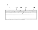
まず、本発明に係る漏洩検知管について説明する。ここで、図1は漏洩検知管の構成を示す管軸直交断面図、図2、図3は漏洩検知管の管軸方向に沿った正面図、図4は漏洩検知管の別の実施形態の構成を示す管軸直交断面図、図5は図4の内管の管軸方向に沿った正面図、図6は漏洩検知管の別の実施形態の構成を示す管軸直交断面図である。
Hereinafter, embodiments of the present invention will be described in detail with reference to the drawings.
First, the leak detection tube according to the present invention will be described. Here, FIG. 1 is a cross-sectional view orthogonal to the tube axis showing the configuration of the leak detection tube, FIGS. 2 and 3 are front views along the tube axis direction of the leak detection tube, and FIG. 4 is another embodiment of the leak detection tube. FIG. 5 is a front view along the tube axis direction of the inner tube of FIG. 4, and FIG. 6 is a tube axis orthogonal cross-sectional view showing the configuration of another embodiment of the leak detection tube.
《漏洩検知管:第1実施形態》
図1に示すように、漏洩検知管1Aは、内管7Bと、内管7Bの外側に嵌合する外管2Aを備え、内管7Bの内側に水または冷媒(以下、熱媒体と称す)の一方を流通させると共に、外管2Aの外側に熱媒体の他方を流通させ、これらの熱媒体間で熱交換を行う熱交換器(熱交換器の構成については後に詳細に説明する)に用いられ、その際に、熱媒体の漏洩を、内管7Bと外管2Aとの間に形成される漏洩路6を介して検知するものである。以下、各構成について説明する。
<< Leakage Detector Tube: First Embodiment >>
As shown in FIG. 1, the
[外管]
外管2Aは、その全長の少なくとも一部の領域に、管周方向に沿って形成された多数の凹部4と凹部4間に形成された凸部5とからなる外管凹凸部3を備え、外管凹凸部3の凹部4および凸部5は外管2Aの管軸方向に沿って伸びている。また、外管2Aは、外管凹凸部3の凹部4の底部の内面が内管7Bに当接している。言い換えれば、外管2Aの最小内径の部分が、内管7Bと当接している。そして、内管7Bの外周面と、外管凹凸部3の凸部5の内面とによって漏洩路6が形成されている。
[Outer tube]
The
外管2Aの外径は、最大外径OD1(外管凹凸部3の凸部5の頂点で外接する外接円の外径)で特定され、漏洩検知管1Aが配置される流路(外管2Aの外側、図9参照)に必要量の熱媒体が流通するように設定される。外管2Aの内径は、最小内径(外管凹凸部3の凹部4の底部で内接する内接円の外径)で特定され、内管7Bの外径に対して相対的に決定されるが、予め内管7Bの外径が決定されている場合、外管2Aの最小径は、内管7Bの外表面に嵌合可能な寸法に設定される。外管2Aの肉厚は、外管2Aの外側を流通する熱媒体による腐食代を考慮した肉厚とすることが好ましく、また、外管凹凸部3によって内管7Bの外周面に嵌合させるための加工を容易に行うことができる肉厚とすることが好ましい。例えば、外管2Aの最大外径OD1はφ3〜20mm、肉厚は0.2〜2.5mm、長さは1〜30mであることが好ましい。
The outer diameter of the
外管2Aの材質は、前記の通りに外管凹凸部3を形成することができる限りにおいて、特に限定されず、熱交換器に用いるために必要な強度、耐食性、ろう付け性、曲げ加工性を有するものを使用することができ、例えば、熱交換器として広く用いられているJISH3300に規定する合金番号C1101の無酸素銅、合金番号C1201およびC1220のりん脱酸銅のいずれかが好ましい。また、前記の材質のみに限定する必要はなく、特に熱伝導性と耐圧強度が必要な場合は、JISH3300に規定された銅または銅合金や、例えば、CuにFe,P,Ni,Co,Mn,Sn,Si,Mg,Ag,Al等の元素より選択する1種または2種以上を総計で数%以下含有させたJISH3300に規定されていない銅合金を用いることも可能である。さらに、特に耐食性と耐圧強度が必要な場合には、JISH3300に規定された合金番号C7060、C7100、C7150などのCu−Ni系合金、TiまたはTi合金、ステンレス鋼などを用いることも可能である。また、軽量化が求められる場合には、耐食性、強度、加工性などの特性を考慮して、アルミニウム、アルミニウム合金の中から所定の特性を有するものを選択することも可能である。
The material of the
なお、熱交換器では、外管2Aの内部に設けられる内管7Bの内圧を高くして運転されることが多いため、外管2Aは、管外径に対する肉厚を大きくすることが多く、外管2Aの肉厚は、熱交換器の運転圧力に基づいて計算される耐圧強度から決定すればよい。外管2Aには、一般に、押出し素管を圧延、抽伸して製作される継目無し管が多く用いられるが、耐圧強度が要求値を満たせば、溶接管を用いてもよい。
Since the heat exchanger is often operated by increasing the internal pressure of the
外管2Aの管周方向に沿って備えられた外管凹凸部3は、外管2Aの外側を流通する熱媒体を撹拌する作用を有すると共に、外管2Aの管外表面積を増加させる作用を有する。これにより、外管2Aの外側を流通する熱媒体の熱伝達率が向上する。外管凹凸部3は、管軸直交断面において、凹部4の凹部深さHS1と、外管2Aの最大外径OD1との比(HS1/OC1)が0.02〜0.1、凹部4の数が4〜32であることが好ましい。
The outer tube concavo-
比(HS1/OD1)が0.02未満であると、外管2Aの外側を流れる熱媒体の撹拌効果が小さく、漏洩検知管1Aの管外表面積(外管2Aの管外表面積)の増加も少ないため、熱媒体の熱伝達率の向上が期待し難くなる。また、比(HS1/OD1)が0.1を超えると、凹部深さHS1が大きくなりすぎて、外管2Aの製造が困難になりやすい。また、外管2Aの外側を流通する熱媒体の圧力損失が大きくなりやすい。
When the ratio (HS 1 / OD 1 ) is less than 0.02, the stirring effect of the heat medium flowing outside the
凹部4の数が4未満であると、漏洩検知管1Aの管外表面積(外管2Aの管外表面積)の増加が少ないため、熱媒体の熱伝達率の向上が期待し難くなる。また、凹部4の数が32を超えると、外管2Aの製造が困難になりやすい。
If the number of the
外管凹凸部3は、図2では、管軸方向に沿って平行に形成され、管軸に対する凹部4のねじれ角γ1(図3参照)は0度であるが、図3に示すように、管軸方向に沿ってらせん状に形成され、管軸に対する凹部4のねじれ角γ1(凹部4と外管2Aの管軸とがなす角度)が30度以下であることが好ましい。外管凹凸部3がらせん状に形成されていることによって、外管2Aの外側を流れる熱媒体に旋回流が与えられ、圧力損失を小さく抑えながら、熱媒体の熱伝達率を一層向上させることができる。ねじれ角γ1が30度を超えると、外管2Aの製造が困難になりやすい。また、外管2Aの外側を流通する熱媒体の圧力損失が大きくなりやすい。
In FIG. 2, the outer tube
また、外管凹凸部3をらせん状に形成することによって、内管7Bの外周面と、外管凹凸部3の凸部5とによって形成される漏洩路6(図1参照)がらせん状となり、熱媒体の漏洩を迅速に検知することができる。そのため、後記する第3実施形態に係る漏洩検知管1C(図6参照)と比較すると、外管2Aの内周面への条溝12Aの形成、内管7Aの外周面へのリブの形成、外管2Aの内周面および内管7Aの外周面のいずれか一方または両方の粗面化を省略することができる利点がある。
Further, by forming the outer tube
[内管]
図1に示すように、内管7Bとして、漏洩検知管1Aにおいては、平滑管を用いている。内管7Bの内径は、内管7B内を熱媒体が必要量流通することが可能な寸法に設定される。また、内管7Bの肉厚は、内管7B内を流通する熱媒体の圧力に耐え得るように、選定された材料(材質)の強度等を考慮して決定される。内管7Bの材質は特に限定されるものではく、外管2Aと同じ材料を用いてもよいし、異なる材料を用いてもよい。例えば、外径はφ1.5〜18mm、肉厚は0.2〜2mm、長さは1〜30mが好ましい。なお、内管7Bとしては、外管2Aと同様に継目無し管を用いることが多いが、耐圧強度の要求値を満たせば、溶接管を用いてもよい。内管7B内に流通させる熱媒体についての詳細は、漏洩検知管1Aを備えた熱交換器20A(図9参照)について後に説明する際に、併せて述べることとする。
[Inner pipe]
As shown in FIG. 1, a smooth tube is used as the
内管7Bは、その両端の少なくとも一方の管端部を外管2Aの管端部より管軸方向に突出していることが好ましい(図10参照)。このような構成により、熱交換器20Aを製造する際に、漏洩検知管1Aと他の部品との接続が容易となる。この内管7Bの突出長さは、製造する熱交換器20Aのサイズにも依るが、例えば、10〜100mmとすることができる。
The
漏洩検知管1Aは、図示しないが、内管7Bの内表面において管軸方向に沿って条溝が形成されていてもよい。条溝の形成によって、内管7Bの内側を流通する熱媒体が撹拌され、漏洩検知管1Aの伝熱性能が向上する。条溝は、その深さが0.01〜0.2mmであることが好ましい。条溝の深さが0.01mm未満では、内管7Bの内側を流通する熱媒体の撹拌効果が小さく、伝熱性能の向上が期待し難い。条溝の深さが0.2mmを超えると、条溝の成形性が低下しやすい。また、管軸平行断面における条溝のねじれ角が0°(管軸方向に平行に形成された平行条溝)〜45°、管軸直交断面における条溝間に形成されたフィンの山頂角が10〜45°、条溝の溝数は30〜70であることが好ましい。なお、条溝の形成方法について、後記する第3実施形態に係る漏洩検知管1Cに形成される条溝12Aと同様である。
Although
次に、本発明に係る漏洩検知管の別の実施形態について説明する。
《漏洩検知管:第2実施形態》
図4に示すように、漏洩検知管1Bは、内管7Aと、内管7Aの外側に嵌合する外管2Bを備え、内管7Aの内側に熱媒体の一方を流通させると共に、外管2Bの外側に熱媒体の他方を流通させ、これらの熱媒体間で熱交換を行う熱交換器に用いられ、その際に、熱媒体の漏洩を、内管7Aと外管2Bとの間に形成される漏洩路11を介して検知するものである。以下、各構成について説明する。
Next, another embodiment of the leak detection tube according to the present invention will be described.
<< Leakage detection tube: Second embodiment >>
As shown in FIG. 4, the leak detection tube 1B includes an
[外管]
外管2Bは、漏洩検知管1Bにおいては、平滑管を用いている。外管2Bとして平滑管を用いることを除いて、外管2Bに要求される特性は、前記した漏洩検知管1Aの外管2Aと同じであるので、ここでの説明は省略する。
[Outer tube]
The outer tube 2B uses a smooth tube in the leak detection tube 1B. Except for using a smooth tube as the outer tube 2B, the characteristics required for the outer tube 2B are the same as those of the
[内管]
内管7Aは、その全長の少なくとも一部の領域に、管周方向に沿って形成された多数の凹部9と凹部9間に形成された凸部10とからなる内管凹凸部8を備え、内管凹凸部8の凹部9および凸部10は内管7Aの管軸方向に沿って伸びている。また、内管7Aは、内管凹凸部8の凸部10の頂部の外面が外管2Bに当接している。言い換えれば、内管7Aの最大外径OD2の部分で、外管2Bと当接している。そして、外管2Bの内周面と、内管凹凸部8の凹部9の外面とによって漏洩路11が形成されている。
[Inner pipe]
The
内管7Aの外径は、最大外径OD2(内管凹凸部8の凸部10の頂点で外接する外接円の外径、言い換えれば、外管2Bの内径)で特定され、内管7Aの内径は、最小内径(内管凹凸部8の凹部9の底部で内接する内接円の外径)で特定される。
The outer diameter of the
内管7Aの管周方向に沿って備えられた内管凹凸部8は、内管7Aの内側を流通する熱媒体を撹拌する作用を有すると共に、内管7Aの管内表面積を増加させる作用を有する。これにより、内管7Aの内側を流通する熱媒体の熱伝達率が向上する。内管凹凸部8は、管軸直交断面において、凹部9の凹部深さHS2と、内管7Aの最大外径OD2との比(HS2/OC2)が0.02〜0.1、凹部4の数が4〜32であることが好ましい。
The inner tube
比(HS2/OD2)が0.02未満であると、内管7Aの内側を流れる熱媒体の撹拌効果が小さく、漏洩検知管1Bの管内表面積(内管7Aの管内表面積)の増加も少ないため、熱媒体の熱伝達率の向上が期待し難くなる。また、比(HS2/OD2)が0.1を超えると、凹部深さHS2が大きくなりすぎて、内管7Aの製造が困難になりやすい。また、内管7Aの内側を流通する熱媒体の圧力損失が大きくなりやすい。
When the ratio (HS 2 / OD 2 ) is less than 0.02, the stirring effect of the heat medium flowing inside the
凹部9の数が4未満であると、漏洩検知管1Bの管内表面積(内管7Aの管内表面積)の増加も少ないため、熱媒体の熱伝達率の向上が期待し難くなる。また、凹部9の数が32を超えると、内管7Aの製造が困難になりやすい。
If the number of the
内管凹凸部8は、管軸方向に沿って平行に形成され、管軸に対する凹部9のねじれ角γ2(図5参照)は0度であるが、図5に示すように、管軸方向に沿ってらせん状に形成され、管軸に対する凹部9のねじれ角γ2(凹部9と内管7Aの管軸とがなす角度)が30度以下であることが好ましい。内管凹凸部8がらせん状に形成されていることによって、内管7Aの内側を流れる熱媒体に旋回流が与えられ、圧力損失を小さく抑えながら、熱媒体の熱伝達率を一層向上させることができる。ねじれ角γ2が30度を超えると、内管7Aの製造が困難になりやすい。また、内管7Aの内側を流通する熱媒体の圧力損失が大きくなりやすい。
The inner tube
また、内管凹凸部8をらせん状に形成することによって、外管2Bの内周面と、内管凹凸部8の凹部9とによって形成される漏洩路11(図4参照)がらせん状となり、熱媒体の漏洩を迅速に検知することができる。そのため、後記する第3実施形態に係る漏洩検知管1C(図6参照)と比較すると、外管2Aの内周面への条溝12Aの形成、内管7Aの外周面へのリブの形成、外管2Aの内周面および内管7Aの外周面のいずれか一方または両方の粗面化を省略することができる利点がある。
Further, by forming the inner tube
前記した最大外径OD2、最小内径、内管凹凸部8を除いて、内管7Aとして要求される特性は、前記した漏洩検知管1Aの内管7Bと同じであるので、ここでの説明は省略する。
Except for the maximum outer diameter OD 2 , the minimum inner diameter, and the inner tube
《漏洩検知管:第3実施形態》
図6に示すように、漏洩検知管1Cは、内管7Aと、内管7Aの外側に嵌合する外管2Aを備え、外管2Aと内管7Aはそれぞれ、その全長の少なくとも一部の領域に管周方向に沿って形成された多数の凹部と凸部とからなる互いに嵌合する外管凹凸部3と内管凹凸部8を備え、外管凹凸部3の凹部4および凸部5は外管2Aの管軸方向に沿って伸び、かつ内管凹凸部8の凹部9および凸部10は内管7Aの管軸方向に沿って伸びている。
<< Leakage Detector Tube: Third Embodiment >>
As shown in FIG. 6, the
漏洩検知管1Cは、先に説明した漏洩検知管1A、1Bと同様に、内管7Aの内側に熱媒体の一方を流通させると共に、外管2Aの外側に熱媒体の他方を流通させ、熱媒体間で熱交換を行う熱交換器に用いられ、その際に、熱媒体の漏洩を内管7Aと外管2Aとの間に形成される漏洩路12を介して検知する。そして、漏洩路12は、内管7Aの外周面と外管2Aの内周面とによって、すなわち、内管7Aの外周面と外管2Aの内周面との嵌合面の微細な凹凸によって形成されている。
As with the
外管凹凸部3と内管凹凸部8とは、凹部4、凹部9同士、凸部5、凸部10同士が重なり合うようにして嵌合している。そして、漏洩検知管1Cは、外管凹凸部3が、管軸直交断面において、凹部4の凹部深さHS1と外管2Aの最大外径OD1との比(HS1/OC1)が0.02〜0.1、凹部4の数が4〜32であり、内管凹凸部8が、管軸直交断面において、凹部9の凹部深さHS2と内管7Aの最大外径OD2との比(HS2/OD2)が0.02〜0.1、凹部9の数が4〜32であることが好ましい。
The outer tube concavo-
外管凹凸部3および内管凹凸部8が前記比(HS1/OD1、HS2/OD2)、前記凹部の数であることによって、外管2Aの外側および内管7Aの内側を流通する熱媒体が撹拌されると共に、外管2Aの管外表面積および内管7Aの管内表面積が増加する。このため、熱媒体の熱伝達率が一層向上する。なお、比(HS1/OD1、HS2/OD2)、凹部の数の数値限定理由は、前記した第1実施形態(漏洩検知管1A)の外管2A、第2実施形態(漏洩検知管1B)の内管7Aと同じである。
The outer tube
外管凹凸部3と内管凹凸部8とはそれぞれ、管軸方向に沿ってらせん状に形成され、外管凹凸部3において管軸に対する凹部4のねじれ角γ1が30度以下であり、内管凹凸部8において管軸に対する凹部9のねじれ角γ2が30度以下であることが好ましい。これにより、外管2Aの外側、内管7Aの内側を流通する熱媒体に旋回流が与えられ、圧力損失を小さく抑えながら、熱媒体の熱伝達率を一層向上させることができる。特に、熱媒体としての冷媒が、冷凍機油を含む二酸化炭素である場合は、圧力損失の増加を抑えながら、伝熱性能を向上させることができる。なお、ねじれ角γ1、γ2の数値限定理由は、前記した第1実施形態(漏洩検知管1A)の外管2A、第2実施形態(漏洩検知管1B)の内管7Aと同じである。
The outer tube concavo-
前記した外管2A、内管7Aが外管凹凸部3、内管凹凸部8を備えることを除いて、外管2A、内管7Aとして要求される特性は、前記した漏洩検知管1Aの外管2A、漏洩検知管1Bの内管7Aと同じであるので、説明は省略する。
Except that the
漏洩検知管1Cは、内管7Aの外周面と外管2Aの内周面との間に漏洩路12を確保して、漏洩した熱媒体の検知に遅れが生じないように、外管2Aとしては、その内周面に管軸方向にらせん状の条溝12Aが形成された内面溝付管が用いることが好ましい。
The
外管2Aとして用いる内面溝付管は、平滑管内部に溝付プラグを挿入し、管外面に回転する転造体(転造ボール、圧延ロール)を押し当て、溝を転造する方法、または条材の表面に溝を圧延し、条の端部同士を溶接する方法により製作することができる。条溝12Aは、外管2Aまたは内管7Aのどの部分で漏洩が起こっても漏洩を検知でき、かつ、外管2Aと内管7Aの熱伝達を低下させないように設ければよく、例えば、条溝の深さが0.01〜0.2mm、管軸平行断面における条溝12Aのねじれ角が0°(管軸方向に平行に形成された平行条溝)〜45°、管軸直交断面における条溝12A間に形成されたフィンの山頂角が10〜45°、条溝12Aの溝数は30〜70であることが好ましい。これらの範囲であれば、大きなコスト上昇を招くことなく漏洩検知管1Cを製造することができる。
The inner grooved tube used as the
また、図示しないが、外管2Aの内周面に条溝12Aが形成されていない場合には、内管7Aは、その外周面おいて管軸方向にリブが形成されていることが好ましい。このリブは、外管2Aの内周面に形成された条溝12Aと同様に、外管2Aと内管7Aとの間に空間を形成し、この空間が漏洩路として機能する。管軸直交断面におけるリブの高さは0.01〜0.2mmとすることが好ましい。リブの高さが0.01mm未満では、外管2Aと内管7Aとの間に形成される空間の漏洩路としての作用が小さく、一方、0.2mmを超えると.リブの成形性が低下したり、伝熱性能が低下したりするおそれがある。なお、リブは、管軸方向に平行であってもよいし、所定角度をなすようにらせん状に形成されていてもよい。
Although not shown, when the
さらに、図示しないが、外管2Aの内周面に条溝12A、または、内管7Aの外周面にリブが形成されていない場合には、外管2Aの内周面と内管7Aの外周面のいずれか一方または両方が粗面化されていることが好ましい。このような粗面化した表面は、その表面の微少な凹凸によって漏洩路を形成する。こうして形成される漏洩路の大きさは、例えば、粗面化されていない平滑管を嵌合させた二重管構造の嵌合面に形成される隙間に比べて大きなものとなる。
Further, although not shown, when the
粗面化の表面粗さは、管軸方向で測定した最大断面高さRtで4μm以上となることが好ましく、6μm以上となることがさらに好ましい。また、表面粗さを算術平均粗さRaで測定した場合、算術平均粗さRaは0.8μm以上であることが好ましく、1.2μm以上であることがさらに好ましい。なお、粗面化された表面は、ショットブラストや化学研磨、化学エッチング等を行うことによって形成することができる。 The surface roughness of the roughening is preferably 4 μm or more, more preferably 6 μm or more in terms of the maximum cross-sectional height Rt measured in the tube axis direction. Further, when the surface roughness is measured by the arithmetic average roughness Ra, the arithmetic average roughness Ra is preferably 0.8 μm or more, and more preferably 1.2 μm or more. Note that the roughened surface can be formed by performing shot blasting, chemical polishing, chemical etching, or the like.
《漏洩検知管の製造方法》
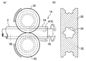
次に、前記した漏洩検知管の製造方法について説明する。ここで、図7(a)は本発明に係る漏洩検知管の製造方法を模式的に示す正面図、(b)は製造に使用される加工冶具の平面図、図8(a)は漏洩検知管の別の製造方法を模式的に示す正面図、(b)は製造に使用される加工用ロールのロール軸に沿った断面図である。
《Leak detector tube manufacturing method》
Next, a method for manufacturing the above-described leak detection tube will be described. Here, FIG. 7A is a front view schematically showing a method for manufacturing a leak detection tube according to the present invention, FIG. 7B is a plan view of a processing jig used for manufacturing, and FIG. 8A is a leak detection. The front view which shows another manufacturing method of a pipe | tube typically, (b) is sectional drawing along the roll axis | shaft of the roll for a process used for manufacture.
図7(a)、(b)に示すように、漏洩検知管1Aの製造においては、最初に、内管7Bを外管2Aの原管2の内側に挿入する。内管7Bが挿入された原管2を、加工冶具30の内側に挿入する。なお、加工冶具30は、凹部4(外管凹凸部3)の断面形状に対応した球面を有するボール31または棒(図示せず)を複数備えている。次に、原管2の外周面に前記のボール31または棒を所定圧で押し当て、同時に原管2を所定速度で管軸方向に移動させる。これにより、原管2が外管凹凸部3を備えた外管2Aに加工され、このとき自然に内管7Bの管軸と外管2Aの管軸が略一致するように内管7Bは外管2Aの中央部に配置され、外管凹凸部3における凹部4の底部(内面)で外管2Aと内管7Bとが嵌合し、外管凹凸部3の凸部5(内面)と内管7Bの外周面との間に漏洩路6(図1参照)が形成され、漏洩検知管1Aが製造される。また、らせん状の外管凹凸部3を形成する場合には、原管2(外管2A)を所定速度で回転させながら、管軸方向に移動させる。
As shown in FIGS. 7A and 7B, in manufacturing the
外管凹凸部3の形成には、前記した加工冶具30の代わりに、図8(a)、(b)に示す一対の加工用ロール32、32を用いてもよい。なお、加工用ロール32は、ロール周方向に溝部を備え、その溝部には凹部4の断面形状に対応した球面状の突起部33を複数備える。
For forming the outer tube
加工用ロール32を用いた漏洩検知管1Aの製造においては、内管7Bが挿入された外管2Aの原管2を、一対の加工用ロール32、32の溝部の内側に挿入する。次に、一対の加工用ロール32、32を閉じ、加工用ロール32、32を所定速度で回転させることにより、原管2を管軸方向に移動させる。これにより、原管2が外管凹凸部3を備えた外管2Aに加工され、外管2Aと内管7Bが嵌合し、漏洩路6が形成された漏洩検知管1Aが製造される。また、らせん状の外管凹凸部3を形成する場合には、加工用ロール32の回転に連動して、原管2(外管2A)を回転させる。また、図示しないが、加工用ロール32として、突起部33を溝部に沿って所定角度で傾斜させたものを使用する。
なお、このような漏洩検知管1Aの製造において、内管7Bとして内面溝付管を用いてもよい。
In manufacturing the
In manufacturing the
漏洩検知管1B(図4参照)の製造においては、図示しないが、前記した加工冶具30、または、加工用ロール32を用いて、前記のようにして内管(原管)を内管7Aに加工する(内管凹凸部8を形成する)。内管7Aを外管(原管)の内側に挿入し、ロール嵌合または抽伸嵌合により外管(原管)を縮径させて外管2Bとする。これにより、内管凹凸部8における凸部10の頂部(外面)で内管7Aと外管2Bとが嵌合し、内管凹凸部8の凹部9(外面)と外管2Bの内周面との間に漏洩路11が形成され、漏洩検知管1Bが製造される。
In the manufacture of the leak detection pipe 1B (see FIG. 4), although not shown, the inner pipe (original pipe) is changed to the
漏洩検知管1C(図6参照)の製造においては、図示しないが、内管(原管)を外管(原管)の内側に挿入し、ロール嵌合または抽伸嵌合により外管(原管)を縮径させ、内管(原管)と外管(原管)が嵌合した二重管とする。次いで、前記した加工冶具30、または、加工用ロール32を用いて、前記のようにして二重管を加工する。これにより、外管(原管)に外管凹凸部3が形成されると同時に、内管(原管)に内管凹凸部8が形成され、外管2A(外管凹凸部3)と内管7A(内管凹凸部8)同士が嵌合した漏洩検知管1Cが製造される。
In manufacturing the
また、外管凹凸部3、内管凹凸部8のそれぞれの凹部深さHS1、HS2はほぼ同一となり、それぞれをらせん状に形成した場合のねじれ角γ1,γ2もほぼ同一となる(HS1=HS2、γ1=γ2)。漏洩路12は、ロール嵌合または抽伸嵌合の際に形成され、外管凹凸部3、内管凹凸部8が形成されても、外管2Aと内管7Aとの間の漏洩路12は維持される。このような漏洩検知管1Cの製造方法において、外管(原管)として内面溝付管を用いてもよい。
Further, the recess depths HS 1 and HS 2 of the outer tube
また、前記した外管凹凸部3、内管凹凸部8の形成方法としては、図1、図4、図6に示す形状の外管凹凸部3、内管凹凸部8が形成できれば、図7(a)、(b)に示す加工冶具30、図8(a)、(b)に示す加工用ロール32を用いた方法に限定されない。
In addition, as a method of forming the outer tube
次に、前記した漏洩検知管を用いた熱交換器について、図面を参照して説明する。
《熱交換器:第1実施形態》
図9は熱交換器の構成を示す管軸直交断面図、図10(a)は本発明の一実施形態に係る熱交換器の管端部の構成を表した斜視図、(b)は熱交換器の概略構造を表した斜視図、図11は別の実施形態に係る熱交換器の管軸方向に沿った断面図である。
Next, a heat exchanger using the above-described leak detection tube will be described with reference to the drawings.
<< Heat Exchanger: First Embodiment >>
9 is a cross-sectional view orthogonal to the tube axis showing the configuration of the heat exchanger, FIG. 10A is a perspective view showing the configuration of the tube end portion of the heat exchanger according to the embodiment of the present invention, and FIG. The perspective view showing the schematic structure of the exchanger, FIG. 11 is sectional drawing along the pipe-axis direction of the heat exchanger which concerns on another embodiment.
熱交換器は、水または冷媒を熱媒体として使用し、これらの熱媒体間で熱交換を行うもので、内側に水または冷媒の一方を流通させる前記漏洩検知管と、漏洩検知管を内包する水または冷媒の他方の流路とを具備する。また、水または冷媒の他方の流路は、管状の大径管13(図9参照)で構成されていることが好ましい。 The heat exchanger uses water or a refrigerant as a heat medium, and performs heat exchange between these heat mediums, and includes the leak detection pipe that circulates either water or the refrigerant inside and the leak detection pipe. And the other flow path of water or refrigerant. Moreover, it is preferable that the other flow path of water or a refrigerant | coolant is comprised by the tubular large diameter tube 13 (refer FIG. 9).
以下、漏洩検知管として図1に示す漏洩検知管1Aを用いた熱交換器を例にとって説明する。図9、図10(a)に示すように、熱交換器20Aは、大径管13の内側に、漏洩検知管1Aが配置された二重管式の構造を有している。そして、熱交換器20Aの管端部には、水と冷媒の流路を隔離するためのキャップ15を備えている。漏洩検知管1Aはキャップ15を貫通しており、大径管13はキャップ15内で開口しており、キャップ15に設けられた開口から水または冷媒が大径管13内に供給される。
Hereinafter, a heat exchanger using the
漏洩検知管1Aの両端の少なくとも一方の管端部においては、内管7Bの管端部が外管2Aの管端部よりも突出していることが好ましい。これによって、漏洩検知管1Aの管端部と、漏洩検知管1A(内管7B)内に水または冷媒を供給する部品(例えば、Uベント管等)との接合が容易となる。
In at least one tube end of both ends of the
図10(a)に示されるように、熱交換器20Aでは、水と冷媒とが対向して流れるように、つまり、水を流す方向と冷媒を流す方向とを逆にすることが好ましい。これにより、管軸方向において水と冷媒との温度差が大きい領域を長い範囲にわたって作り出すことができるため、熱交換性能を向上させることができる。
As shown in FIG. 10A, in the
[漏洩検知管]
漏洩検知管1A内には、水または冷媒を流通させる。冷媒としては、二酸化炭素等の自然冷媒や、代替フロン等が使用され、熱交換器20Aを給湯器用として用いる場合には、特に環境面から二酸化炭素を使用することが好ましく、二酸化炭素を超臨界状態で使用することが、熱効率の観点から、より好ましい。超臨界状態とは気相と液相の境界がなくなった状態であり、密度および粘度が気相状態に近似した低い状態であるにもかかわらず、熱伝達率が気相状態の2倍以上の高い値を示す状態を言う。
[Leak detection tube]
Water or refrigerant is circulated in the
漏洩検知管1Aに備えられている外管凹凸部3(図1〜図3参照)は、熱交換器20Aの実際の運転において、冷媒として二酸化炭素を使用する場合には、二酸化炭素の局所熱伝達率が極大となる許容温度範囲(20〜80℃)を満足する領域に形成することが好ましい。
The outer tube uneven portion 3 (see FIGS. 1 to 3) provided in the
なお、熱媒体として二酸化炭素を用いる場合には、二酸化炭素そのものが潤滑作用を持たないため、熱交換システムのコンプレッサを磨耗させてしまうことがある。そのため、二酸化炭素に0.1〜6.0質量%の冷凍機油を含有させることが好ましい。冷凍機油には、ポリアルキレングリコール(PAG)等が一般的に用いられる。冷凍機油の含有量が0.1質量%未満であると潤滑効果が低く、熱交換システムのコンプレッサを磨耗させやすい。一方、冷凍機油を6.0質量%を超えて含有させると、冷媒全体の熱伝達率が低下しやすい。 In the case where carbon dioxide is used as the heat medium, the carbon dioxide itself does not have a lubricating action, so that the compressor of the heat exchange system may be worn. Therefore, it is preferable to contain 0.1 to 6.0% by mass of refrigerating machine oil in carbon dioxide. For the refrigerating machine oil, polyalkylene glycol (PAG) or the like is generally used. When the content of the refrigerating machine oil is less than 0.1% by mass, the lubrication effect is low and the compressor of the heat exchange system is easily worn. On the other hand, if the refrigerating machine oil is contained in an amount exceeding 6.0 mass%, the heat transfer coefficient of the entire refrigerant tends to be lowered.
冷媒として代替フロンを用いる場合には、熱交換器20Aの成績効率(COP)を考慮すると、ハイドロフルオロカーボン(HFC)系冷媒を用いることが好ましい。代表的なHFC系冷媒としては、R32とR125を混合した非共沸混合冷媒であるR410Aがある。HFC系冷媒もほぼ臨界状態で使用することが好ましい。
When using alternative chlorofluorocarbon as the refrigerant, it is preferable to use a hydrofluorocarbon (HFC) refrigerant in consideration of the performance efficiency (COP) of the
また、熱交換器20Aでは、大径管13内に1本の漏洩検知管1Aが配置された構造としているが、大径管13内に複数本の漏洩検知管1Aを配置した構成としてもよい。漏洩検知管1Aを複数設ける場合には、熱伝達、圧力損失の点から、大径管13内の水または冷媒の流路が均等に分割されるようにすることが好ましい。
The
漏洩検知管1A自体の構造の詳細については、既に説明しているので、ここでの説明は省略する。また、漏洩検知管1Aの代わりに、図4、図6に示す漏洩検知管1B、1Cを用いた熱交換器においても、前記した熱交換器20Aと同様である。さらに、漏洩検知管1B、1Cを用いた熱交換器では、漏洩検知管1B、1C(内管7A)の管端部には、内管凹凸部8を形成させないことが好ましい。これによって、漏洩検知管1B、1Cの管端部と、漏洩検知管1B、1C(内管7A)内に水または冷媒を供給する部品(例えば、Uベント管等)との接合が容易となる。
Since the details of the structure of the
[大径管]
大径管13は、漏洩検知管1Aとの間に水または冷媒の流路を形成するものである。大径管13の内径は、漏洩検知管1Aの外径より大きく、流路に水または冷媒を流すのに十分な大きさであればよく、また、大径管13は必要とされる耐圧強度を有していればよい。大径管13の寸法は、漏洩検知管1Aの寸法との関係、熱交換器20Aが組み込まれる給湯器等の寸法、熱容量、加工性を考慮して決められる。熱交換器20Aの熱交換性能や圧力損失の点から、管軸直交断面における漏洩検知管1Aの断面積(漏洩検知管1Aの本数×大径管13の管軸直交断面における漏洩検知管1Aの断面積)と、大径管13と漏洩検知管1Aとの間の流路の断面積との比(外側流路面積/漏洩検知管断面積)が2〜10の範囲内を満足するように設定することがより好ましい。一例として、大径管13は、内径はφ8〜30mm、肉厚は0.2〜2.5mm、長さは1〜30mであることが好ましい。
[Large diameter pipe]
The large-
熱交換器20Aは、図10(b)に示されるように、大径管13が、巻回軸Yに対して直交する断面形状が円形状または小判状となるように、らせん状に巻回された構造を有しており、このような構成とすることによって、熱交換器20Aをコンパクト化しながらも広い伝熱面積を確保することができる。また、巻回部には急角度に曲げられた部分がないために、水と冷媒のそれぞれの圧力損失を小さくすることができる。また、大径管13が、渦巻状に巻回された構造であってもよい。
As shown in FIG. 10B, the
大径管13の巻回部の最小内径IDは、大径管13および漏洩検知管1Aの管外径、肉厚、機械的性質(引張強さ、耐力、ばね限界値等)等に依存するが、例えば、大径管13の管外径を定数“a”とすると、巻回部の最小内径IDは“a”の6倍程度まで小さくすることが可能である。また、巻回部の高さHを小さくするために、図10(b)には一重巻き構造としたが、二重巻き構造とすることも好ましい。大径管13の巻回部においては、大径管13同士は接触していてもよいし、一定の隙間によって離間している状態としてもよい。熱交換器20Aのコンパクト化の点からは、大径管13同士を接触させることが好ましい。
The minimum inner diameter ID of the winding portion of the large-
大径管13の材質は、特に限定されず、熱交換器20Aに必要な強度、耐食性、ろう付け性、曲げ加工性を有するものを使用すればよく、例えば、漏洩検知管1Aの外管2Aおよび内管7Bに使用されるものとして前記した材料から適宜選択することができる。大径管13は、押出し素管を圧延、抽伸して製作される継目無し管、あるいは所定幅の板の幅方向の端面を溶接して製作される溶接管を用いてもよい。なお、熱交換器では、JISH3300に規定する合金番号C1101の無酸素銅、合金番号C1201およびC1220のりん脱酸銅が広く用いられている。
The material of the
大径管13としては、管内面が平滑である平滑管が用いられることが多く、熱交換器20Aにおいても、図9に示されるように、平滑管を用いているが、大径管13として、内周面に条溝が形成された内面溝付管を使用してもよい。このような内面溝付管を用いることにより、大径管13内を流れる水または冷媒が撹拌され、旋回流が与えられて、水または冷媒の熱伝達性能を向上させることができる。
As the
次に、本発明に係る熱交換器の別の実施形態について説明する。
《熱交換器:第2実施形態》
図11に示すように、熱交換器20Bは、大径管13Aの内側に、漏洩検知管1Aが配置された二重管式の構造を有している。
Next, another embodiment of the heat exchanger according to the present invention will be described.
<< Heat Exchanger: Second Embodiment >>
As shown in FIG. 11, the heat exchanger 20B has a double-pipe structure in which the
[漏洩検知管]
漏洩検知管1Aについては、既に図1〜図3を参照して説明しているため、ここでの説明は省略する。
[Leak detection tube]
Since the
[大径管]
大径管13Aは、その全長の少なくとも一部の領域に管軸方向に沿ってコルゲート加工された加工部14を備える。このような構成により、大径管13A内を流れる水または冷媒は、加工部14により撹拌され、また、水または冷媒の流路長が実質的に長くなるために、水または冷媒の熱伝達率を一層向上させることができる。
[Large diameter pipe]
The large-
加工部14は、大径管13Aの管軸直交断面において、溝深さHCと、最大外径(コルゲート加工されていない未加工部の管外径)DCとの比(HC/DC)が、0.02以上(HC/DC≧0.02)であることが好ましい。これにより、漏洩検知管1Aの外径と大径管13Aの内径との差が大きい場合にも、水または冷媒を十分に撹拌して、水または冷媒の熱伝達性能を向上させることができる。
The processed
また、加工部14をらせん状に形成する場合のねじれ角γ3については、水または冷媒を十分に撹拌して、水または冷媒の熱伝達率を向上させる点から、40度以上(γ3≧40°)とすることが好ましく、加工部14の管軸方向に形成される条数は1以上であればよい。なお、本発明において、コルゲート加工には、ねじれ角γ3=90度、すなわち、らせん状でない加工部14の形成も含まれる。
In addition, with respect to the twist angle γ 3 when the processed
前記した加工部14を備えることを除いて、大径管13Aとして要求される特性は、前記の第1実施形態の熱交換器20Aの大径管13と同様であるので、ここでは説明を省略する。なお、大径管13Aとして、図示しないが、加工部14に代わって、内周面に条溝が形成された内面溝付管を使用してもよい。
Except for the provision of the processed
次に、本発明を実施例により説明するが、本発明は以下の実施例に限定されるものではない。 EXAMPLES Next, although an Example demonstrates this invention, this invention is not limited to a following example.
《実施例1》
漏洩検知管を構成する外管として、りん脱酸銅からなり、外径:φ6mm、内径:φ4.8mmの平滑管(肉厚:0.6mm)と、内管として、りん脱酸銅からなり、外径:φ4.0mm、内径:φ3.0mmの平滑管(肉厚:0.5mm)とを準備した。外管に内管を挿入した状態で、加工冶具30(図7参照)を用いて外管凹凸部3を形成し、外管2Aを内管7Bに嵌合させて、漏洩検知管1A(図1、図2参照)を製造した。
このとき、漏洩検知管1Aの外管凹凸部3は、凹部深さ(HS1):0.4mm、ねじれ角:0度、凹部の数:16、凹凸部長さ(嵌合部長さ):5mとした。また、漏洩検知管1Aは、両管端において、内管7Bを外管2Aから25mm突出させた(図10参照)。
こうして作製した2本の漏洩検知管1Aを、外径:φ15.88mm、内径:φ14.68mmの大径管に挿入し、二重管式の熱交換器20Aとした。
Example 1
The outer tube composing the leak detection tube is made of phosphorous deoxidized copper, the outer diameter is φ6mm, the inner diameter is φ4.8mm smooth tube (thickness: 0.6mm), and the inner tube is made of phosphorous deoxidized copper. A smooth tube (wall thickness: 0.5 mm) having an outer diameter of φ4.0 mm and an inner diameter of φ3.0 mm was prepared. With the inner tube inserted into the outer tube, the outer tube
At this time, the outer tube
The two
《実施例2》
漏洩検知管を構成する外管として、りん脱酸銅からなり、外径:φ6.3mm、内径:5.1mmの平滑管(肉厚:0.6mm)と、内管として、りん脱酸銅からなり、外径:φ4.8mm、内径:φ3.8mmの平滑管(肉厚:0.5mm)を準備した。内管に、加工冶具30(図7参照)を用いて内管凹凸部を形成した。内管凹凸部が形成された内管を外管の内側に挿入して、ロールを用いて外管と内管とを嵌合し、外径:φ6mmの漏洩検知管1B(図4参照)を製造した。
このとき、漏洩検知管1Bの内管凹凸部8は、凹部深さ(HS2):0.4mm、ねじれ角:0度、凹部の数:16、凹凸部長さ(嵌合部長さ):5mとした。また、漏洩検知管1Bは、両管端において、内管7Aを外管2Bから25mm突出させた(突出した内管7Aの突出部には内管凹凸部8は形成されていない)。
こうして製造した2本の漏洩検知管1Bを、外径:φ15.88mm、内径:φ14.68mmの大径管に挿入し、二重管式の熱交換器とした。
Example 2
The outer tube constituting the leak detection tube is made of phosphorous deoxidized copper. The outer tube is a smooth tube (wall thickness: 0.6 mm) with an outer diameter of φ6.3 mm and the inner diameter: 5.1 mm. The inner tube is phosphorous-deoxidized copper. A smooth tube (wall thickness: 0.5 mm) having an outer diameter of φ4.8 mm and an inner diameter of φ3.8 mm was prepared. On the inner tube, an inner tube uneven portion was formed using a processing jig 30 (see FIG. 7). The inner tube with the inner tube irregularities formed is inserted inside the outer tube, and the outer tube and the inner tube are fitted using a roll, and a leak detection tube 1B (see FIG. 4) having an outer diameter of φ6 mm is used. Manufactured.
At this time, the inner tube
The two leak detection tubes 1B thus manufactured were inserted into a large-diameter tube having an outer diameter of φ15.88 mm and an inner diameter of φ14.68 mm to obtain a double tube heat exchanger.
《実施例3》
漏洩検知管を構成する外管として、りん脱酸銅からなり、外径:φ6.3mm、内径:5.1mmの平滑管(肉厚:0.6mm)と、内管として、りん脱酸銅からなり、外径:φ4.8mm、内径:φ3.8mmの平滑管(肉厚:0.5mm)を準備した。外管に内管を挿入して、ロールを用いて外管と内管を嵌合し、外径:φ6mm、ロール嵌合による嵌合部長さ:5m、両管端において、内管を外管から25mm突出させた二重管とした。この二重管に、加工冶具30(図7参照)を用いて外管凹凸部、内管凹凸部を形成し、外径:φ6mmの漏洩検知管1C(図6参照)を製造した。
このとき、漏洩検知管1Cの外管凹凸部は、凹部深さ(HS1):0.4mm、凹部の数:16、ねじれ角:0度とし、内管凹凸部8は、凹部深さ(HS2):0.4mm、ねじれ角:0度、凹部の数:16とした。
こうして製造した2本の漏洩検知管1Cを、外径:φ15.88mm、内径:φ14.68mmの大径管に挿入し、二重管式の熱交換器とした。
Example 3
The outer tube constituting the leak detection tube is made of phosphorous deoxidized copper. The outer tube is a smooth tube (wall thickness: 0.6 mm) with an outer diameter of φ6.3 mm and the inner diameter: 5.1 mm. The inner tube is phosphorous-deoxidized copper. A smooth tube (wall thickness: 0.5 mm) having an outer diameter of φ4.8 mm and an inner diameter of φ3.8 mm was prepared. Insert the inner tube into the outer tube, fit the outer tube and inner tube using a roll, outer diameter: φ6mm, fitting part length by roll fitting: 5m, the inner tube is the outer tube at both tube ends It was set as the double tube made to protrude from 25 mm. An outer tube uneven portion and an inner tube uneven portion were formed on the double tube using a processing jig 30 (see FIG. 7), and a
At this time, the outer tube uneven portion of the
The two
《比較例》
漏洩検知管を構成する外管として、りん脱酸銅からなり、外径:φ6.3mmの内面溝付管であって、その内面溝形状は、底肉厚:0.6mm、溝深さ:0.15mm、溝数:50、リード角:20°のものを準備し、また、内管として、りん脱酸銅からなり、外径:φ4.8mm、内径:φ3.8mmの平滑管(肉厚:0.5mm)を準備した。外管に内管を挿入してロールを用いて嵌合し、外径:φ6mmとした。このときのロール嵌合による嵌合部長さを5mとし、両管端において内管を外管から25mm突出させた漏洩検知管を製造した。
こうして製造した2本の漏洩検知管を外径:φ15.88mm、内径:φ14.68mmの大径管に挿入し、二重管式の熱交換器とした。
《Comparative example》
The outer tube constituting the leak detection tube is made of phosphorous deoxidized copper, and is an inner grooved tube having an outer diameter of φ6.3 mm. The inner groove shape has a bottom wall thickness of 0.6 mm and a groove depth: A 0.15 mm, groove number: 50, lead angle: 20 ° tube is prepared, and the inner tube is made of phosphorous-deoxidized copper and has an outer diameter of φ4.8 mm and an inner diameter of φ3.8 mm. (Thickness: 0.5 mm) was prepared. The inner tube was inserted into the outer tube and fitted using a roll, and the outer diameter was 6 mm. At this time, the length of the fitting portion by roll fitting was set to 5 m, and a leak detection tube in which the inner tube protruded from the outer tube by 25 mm at both tube ends was manufactured.
The two leak detection tubes thus manufactured were inserted into a large-diameter tube having an outer diameter of φ15.88 mm and an inner diameter of φ14.68 mm to obtain a double-tube heat exchanger.
《熱交換性能評価》
実施例1〜3、比較例の熱交換器を2本直列に並べた。大径管の内部に形成された環状の流路に20℃に調整した水を1L(リットル)/minで流し、漏洩検知管の内部に、水を流す方向とは逆の方向に、超臨界状態の二酸化炭素(圧力:9MPa、流量:1kg/min)を流して、水の出口側での温度を測定し、熱交換量を算出した。比較例の熱交換量を100とし、実施例1〜3の熱交換量を相対値として算出した。結果を表1に示す。
<Evaluation of heat exchange performance>
Two heat exchangers of Examples 1 to 3 and Comparative Example were arranged in series. Supercritical water is flown at a rate of 1 L (liter) / min through an annular channel formed inside the large-diameter tube at a rate of 1 L (min) / min. Carbon dioxide (pressure: 9 MPa, flow rate: 1 kg / min) was flowed in the state, the temperature at the outlet side of water was measured, and the heat exchange amount was calculated. The heat exchange amount of the comparative example was set to 100, and the heat exchange amounts of Examples 1 to 3 were calculated as relative values. The results are shown in Table 1.

表1の結果から、実施例1〜3の熱交換器は、比較例の熱交換器に比べて熱交換量が多く、熱交換性能に優れていることが確認された。 From the results in Table 1, it was confirmed that the heat exchangers of Examples 1 to 3 had a larger amount of heat exchange than the heat exchangers of the comparative examples and were excellent in heat exchange performance.
1A、1B、1C 漏洩検知管
2A、2B 外管
3 外管凹凸部
4 凹部
5 凸部
6 漏洩路
7A、7B 内管
8 内管凹凸部
9 凹部
10 凸部
11、12 漏洩路
13 大径管
20A、20B 熱交換器
1A, 1B, 1C
Claims (18)
前記外管は、その全長の少なくとも一部の領域に、管周方向に沿って形成された多数の凹部と凸部とからなる外管凹凸部を備え、前記外管凹凸部の前記凹部および前記凸部は前記外管の管軸方向に沿って伸び、
前記外管は、前記外管凹凸部の前記凹部の底部の内面が前記内管に当接し、
前記漏洩路は、前記内管の外周面と前記外管凹凸部の前記凸部の内面とによって形成されていることを特徴とする漏洩検知管。 An inner pipe and an outer pipe fitted to the outside of the inner pipe, and leakage of water or refrigerant flowing inside the inner pipe or outside the outer pipe between the inner pipe and the outer pipe. A leak detection tube that detects through a leak path formed,
The outer tube is provided with an outer tube concavo-convex portion including a plurality of concave portions and convex portions formed along the pipe circumferential direction in at least a partial region of the entire length, and the concave portion of the outer pipe concavo-convex portion and the The convex portion extends along the tube axis direction of the outer tube,
In the outer tube, the inner surface of the bottom of the concave portion of the outer tube uneven portion is in contact with the inner tube,
The leak detection tube according to claim 1, wherein the leak path is formed by an outer peripheral surface of the inner tube and an inner surface of the convex portion of the outer tube uneven portion.
前記内管は、その全長の少なくとも一部の領域に、管周方向に沿って形成された多数の凹部と凸部とからなる内管凹凸部を備え、前記内管凹凸部の前記凹部および前記凸部は前記内管の管軸方向に沿って伸び、
前記内管は、前記内管凹凸部の前記凸部の頂部の外面が前記外管に当接し、
前記漏洩路は、前記外管の内周面と前記内管凹凸部の前記凹部の外面とによって形成されていることを特徴とする漏洩検知管。 An inner pipe and an outer pipe fitted to the outside of the inner pipe, and leakage of water or refrigerant flowing inside the inner pipe or outside the outer pipe between the inner pipe and the outer pipe. A leak detection tube that detects through a leak path formed,
The inner tube includes an inner tube uneven portion formed of a large number of recesses and protrusions formed along the tube circumferential direction in at least a partial region of the entire length thereof, and the recesses of the inner tube uneven portion and the The convex portion extends along the tube axis direction of the inner tube,
In the inner tube, the outer surface of the top of the convex portion of the inner tube uneven portion is in contact with the outer tube,
The leak detection tube according to claim 1, wherein the leak path is formed by an inner peripheral surface of the outer tube and an outer surface of the concave portion of the inner tube uneven portion.
前記外管と前記内管は、その全長の少なくとも一部の領域に、管周方向に沿って形成された多数の凹部と凸部とからなる互いに嵌合する外管凹凸部と内管凹凸部を備え、前記外管凹凸部の前記凹部および前記凸部は前記外管の管軸方向に沿って伸び、かつ前記内管凹凸部の前記凹部および前記凸部は前記内管の管軸方向に沿って伸び、
前記漏洩路は、前記内管の外周面と前記外管の内周面とによって形成されていることを特徴とする漏洩検知管。 An inner pipe and an outer pipe fitted to the outside of the inner pipe, and leakage of water or refrigerant flowing inside the inner pipe or outside the outer pipe between the inner pipe and the outer pipe. A leak detection tube that detects through a leak path formed,
The outer tube and the inner tube have an outer tube uneven portion and an inner tube uneven portion that are fitted to each other and include a large number of concave portions and convex portions formed along the pipe circumferential direction in at least a partial region of the entire length. The concave portion and the convex portion of the outer tube uneven portion extend along the tube axis direction of the outer tube, and the concave portion and the convex portion of the inner tube uneven portion are in the tube axis direction of the inner tube. Stretches along,
The leak detection pipe, wherein the leak path is formed by an outer peripheral surface of the inner pipe and an inner peripheral face of the outer pipe.
前記内管凹凸部は、管軸直交断面において、前記凹部の凹部深さHS2と前記内管の最大外径OD2との比(HS2/OD2)が0.02〜0.1、前記凹部の数が4〜32であることを特徴とする請求項7に記載の漏洩検知管。 The outer tube concavo-convex portion has a ratio (HS 1 / OC 1 ) between a recess depth HS 1 of the recess and a maximum outer diameter OD 1 of the outer tube of 0.02 to 0.1 in a cross section orthogonal to the tube axis. The number of the recesses is 4 to 32,
The inner tube uneven portion has a ratio (HS 2 / OD 2 ) between the recess depth HS 2 of the recess and the maximum outer diameter OD 2 of the inner tube of 0.02 to 0.1 in the cross section orthogonal to the tube axis. The leak detection tube according to claim 7, wherein the number of the recesses is 4 to 32.
前記外管凹凸部において、管軸に対する前記凹部のねじれ角γ1が30度以下であり、
前記内管凹凸部において、管軸に対する前記凹部のねじれ角γ2が30度以下であることを特徴とする請求項8に記載の漏洩検知管。 The outer tube uneven portion and the inner tube uneven portion are each formed in a spiral shape along the tube axis direction,
In the outer tube uneven portion, the twist angle γ1 of the recess with respect to the tube axis is 30 degrees or less,
The leak detection tube according to claim 8, wherein in the inner tube uneven portion, a twist angle γ2 of the recess with respect to the tube axis is 30 degrees or less.
その内側に水または冷媒の一方を流通させる請求項1から請求項12のいずれか一項に記載の漏洩検知管と、
前記漏洩検知管を内包する水または冷媒の他方の流路とを具備することを特徴とする熱交換器。 A heat exchanger that uses water and a refrigerant as a heat medium, and performs heat exchange between these heat mediums,
The leak detection tube according to any one of claims 1 to 12, wherein one of water and a refrigerant is circulated inside the inside.
A heat exchanger comprising the other flow path of water or refrigerant containing the leak detection pipe.
Priority Applications (1)
| Application Number | Priority Date | Filing Date | Title |
|---|---|---|---|
| JP2008088090A JP2009243715A (en) | 2008-03-28 | 2008-03-28 | Leakage detecting tube and heat exchanger |
Applications Claiming Priority (1)
| Application Number | Priority Date | Filing Date | Title |
|---|---|---|---|
| JP2008088090A JP2009243715A (en) | 2008-03-28 | 2008-03-28 | Leakage detecting tube and heat exchanger |
Publications (1)
| Publication Number | Publication Date |
|---|---|
| JP2009243715A true JP2009243715A (en) | 2009-10-22 |
Family
ID=41305821
Family Applications (1)
| Application Number | Title | Priority Date | Filing Date |
|---|---|---|---|
| JP2008088090A Pending JP2009243715A (en) | 2008-03-28 | 2008-03-28 | Leakage detecting tube and heat exchanger |
Country Status (1)
| Country | Link |
|---|---|
| JP (1) | JP2009243715A (en) |
Cited By (10)
| Publication number | Priority date | Publication date | Assignee | Title |
|---|---|---|---|---|
| CN102235751A (en) * | 2011-03-08 | 2011-11-09 | 海尔集团公司 | Heat exchange tube of water heater and manufacturing method thereof |
| JP2012007770A (en) * | 2010-06-23 | 2012-01-12 | Panasonic Corp | Heat exchanger |
| JP2012007772A (en) * | 2010-06-23 | 2012-01-12 | Panasonic Corp | Heat exchanger |
| DE102011088222A1 (en) | 2010-12-17 | 2012-06-21 | Denso Corporation | Multi-tube heat exchanger for heat exchange between refrigerant and water, comprises outer tube and inner tube, which is arranged in outer tube, where outer passage is defined between outer tube and inner tube |
| JP2012237518A (en) * | 2011-05-12 | 2012-12-06 | Fujitsu General Ltd | Air conditioner |
| JP2013127321A (en) * | 2011-12-16 | 2013-06-27 | Kobelco & Materials Copper Tube Inc | Heat transfer tube having leakage detection function, and outer tube used for the same |
| KR101284536B1 (en) * | 2011-01-10 | 2013-07-09 | 자동차부품연구원 | Apparatus for preheating of coolant using exhaust gas heat |
| JP2015010757A (en) * | 2013-06-28 | 2015-01-19 | 岩谷マテリアル株式会社 | Triple-tube type heat exchanger |
| JP2015010758A (en) * | 2013-06-28 | 2015-01-19 | 岩谷マテリアル株式会社 | Triple-tube type heat exchanger |
| JP2015025577A (en) * | 2013-07-24 | 2015-02-05 | 岩谷マテリアル株式会社 | Method of manufacturing triple tube type heat exchanger |
-
2008
- 2008-03-28 JP JP2008088090A patent/JP2009243715A/en active Pending
Cited By (10)
| Publication number | Priority date | Publication date | Assignee | Title |
|---|---|---|---|---|
| JP2012007770A (en) * | 2010-06-23 | 2012-01-12 | Panasonic Corp | Heat exchanger |
| JP2012007772A (en) * | 2010-06-23 | 2012-01-12 | Panasonic Corp | Heat exchanger |
| DE102011088222A1 (en) | 2010-12-17 | 2012-06-21 | Denso Corporation | Multi-tube heat exchanger for heat exchange between refrigerant and water, comprises outer tube and inner tube, which is arranged in outer tube, where outer passage is defined between outer tube and inner tube |
| KR101284536B1 (en) * | 2011-01-10 | 2013-07-09 | 자동차부품연구원 | Apparatus for preheating of coolant using exhaust gas heat |
| CN102235751A (en) * | 2011-03-08 | 2011-11-09 | 海尔集团公司 | Heat exchange tube of water heater and manufacturing method thereof |
| JP2012237518A (en) * | 2011-05-12 | 2012-12-06 | Fujitsu General Ltd | Air conditioner |
| JP2013127321A (en) * | 2011-12-16 | 2013-06-27 | Kobelco & Materials Copper Tube Inc | Heat transfer tube having leakage detection function, and outer tube used for the same |
| JP2015010757A (en) * | 2013-06-28 | 2015-01-19 | 岩谷マテリアル株式会社 | Triple-tube type heat exchanger |
| JP2015010758A (en) * | 2013-06-28 | 2015-01-19 | 岩谷マテリアル株式会社 | Triple-tube type heat exchanger |
| JP2015025577A (en) * | 2013-07-24 | 2015-02-05 | 岩谷マテリアル株式会社 | Method of manufacturing triple tube type heat exchanger |
Similar Documents
| Publication | Publication Date | Title |
|---|---|---|
| JP2009243715A (en) | Leakage detecting tube and heat exchanger | |
| JP6172950B2 (en) | Double tube for heat exchanger | |
| KR100918216B1 (en) | Heat transfer tube with inner surface grooves, used for high-pressure refrigerant | |
| JP2007218486A (en) | Heat transfer tube for heat exchanger, and heat exchanger using the same | |
| RU2289076C2 (en) | Pipes with grooves for reversible usage at heat exchangers | |
| JP2006242529A (en) | Heat transfer pipe | |
| JP2007271122A (en) | Heat exchanger | |
| JP2008164245A (en) | Heat exchanger | |
| JP2008190858A (en) | Leakage detecting tube | |
| JP2006322661A (en) | Heat transfer tube for heat dissipation, and radiator | |
| JP2008261566A (en) | Double-pipe heat exchanger | |
| JP2008267791A (en) | Leakage detecting tube and heat exchanger using the same | |
| JP2006046888A (en) | Composite heat exchanger tube | |
| JP2005257160A (en) | Heat transfer pipe with grooved inner surface and heat exchanger using the heat transfer tube with grooved inner surface | |
| JP2011075122A (en) | Aluminum internally-grooved heat transfer tube | |
| WO2011162170A1 (en) | Double tube for heat exchanger | |
| JP2009186130A (en) | Heat transfer tube for radiator with inner face fin | |
| JP2007271238A (en) | Heat exchanger | |
| JP2009229032A (en) | Leakage detecting tube and heat exchanger | |
| JP5006155B2 (en) | Heat transfer tube | |
| JP2008107013A (en) | Heat transfer tube having leakage detecting mechanism and heat exchanger using the same | |
| WO2012017777A1 (en) | Double pipe for heat exchanger | |
| JP2010019489A (en) | Heat transfer pipe with inner helical groove for evaporator | |
| JP2007032943A (en) | Composite heat exchanger tube | |
| JP5540683B2 (en) | Heat exchanger and water heater provided with the same |