JP2009241663A - Working vehicle - Google Patents
Working vehicle Download PDFInfo
- Publication number
- JP2009241663A JP2009241663A JP2008088785A JP2008088785A JP2009241663A JP 2009241663 A JP2009241663 A JP 2009241663A JP 2008088785 A JP2008088785 A JP 2008088785A JP 2008088785 A JP2008088785 A JP 2008088785A JP 2009241663 A JP2009241663 A JP 2009241663A
- Authority
- JP
- Japan
- Prior art keywords
- wheel steering
- steering mode
- speed
- gear
- vehicle speed
- Prior art date
- Legal status (The legal status is an assumption and is not a legal conclusion. Google has not performed a legal analysis and makes no representation as to the accuracy of the status listed.)
- Pending
Links
Images


Classifications
-
- B—PERFORMING OPERATIONS; TRANSPORTING
- B60—VEHICLES IN GENERAL
- B60W—CONJOINT CONTROL OF VEHICLE SUB-UNITS OF DIFFERENT TYPE OR DIFFERENT FUNCTION; CONTROL SYSTEMS SPECIALLY ADAPTED FOR HYBRID VEHICLES; ROAD VEHICLE DRIVE CONTROL SYSTEMS FOR PURPOSES NOT RELATED TO THE CONTROL OF A PARTICULAR SUB-UNIT
- B60W10/00—Conjoint control of vehicle sub-units of different type or different function
- B60W10/20—Conjoint control of vehicle sub-units of different type or different function including control of steering systems
-
- B—PERFORMING OPERATIONS; TRANSPORTING
- B60—VEHICLES IN GENERAL
- B60W—CONJOINT CONTROL OF VEHICLE SUB-UNITS OF DIFFERENT TYPE OR DIFFERENT FUNCTION; CONTROL SYSTEMS SPECIALLY ADAPTED FOR HYBRID VEHICLES; ROAD VEHICLE DRIVE CONTROL SYSTEMS FOR PURPOSES NOT RELATED TO THE CONTROL OF A PARTICULAR SUB-UNIT
- B60W10/00—Conjoint control of vehicle sub-units of different type or different function
- B60W10/10—Conjoint control of vehicle sub-units of different type or different function including control of change-speed gearings
- B60W10/11—Stepped gearings
- B60W10/111—Stepped gearings with separate change-speed gear trains arranged in series
-
- B—PERFORMING OPERATIONS; TRANSPORTING
- B62—LAND VEHICLES FOR TRAVELLING OTHERWISE THAN ON RAILS
- B62D—MOTOR VEHICLES; TRAILERS
- B62D7/00—Steering linkage; Stub axles or their mountings
- B62D7/06—Steering linkage; Stub axles or their mountings for individually-pivoted wheels, e.g. on king-pins
- B62D7/14—Steering linkage; Stub axles or their mountings for individually-pivoted wheels, e.g. on king-pins the pivotal axes being situated in more than one plane transverse to the longitudinal centre line of the vehicle, e.g. all-wheel steering
- B62D7/15—Steering linkage; Stub axles or their mountings for individually-pivoted wheels, e.g. on king-pins the pivotal axes being situated in more than one plane transverse to the longitudinal centre line of the vehicle, e.g. all-wheel steering characterised by means varying the ratio between the steering angles of the steered wheels
- B62D7/1509—Steering linkage; Stub axles or their mountings for individually-pivoted wheels, e.g. on king-pins the pivotal axes being situated in more than one plane transverse to the longitudinal centre line of the vehicle, e.g. all-wheel steering characterised by means varying the ratio between the steering angles of the steered wheels with different steering modes, e.g. crab-steering, or steering specially adapted for reversing of the vehicle
-
- B—PERFORMING OPERATIONS; TRANSPORTING
- B60—VEHICLES IN GENERAL
- B60W—CONJOINT CONTROL OF VEHICLE SUB-UNITS OF DIFFERENT TYPE OR DIFFERENT FUNCTION; CONTROL SYSTEMS SPECIALLY ADAPTED FOR HYBRID VEHICLES; ROAD VEHICLE DRIVE CONTROL SYSTEMS FOR PURPOSES NOT RELATED TO THE CONTROL OF A PARTICULAR SUB-UNIT
- B60W2520/00—Input parameters relating to overall vehicle dynamics
- B60W2520/10—Longitudinal speed
-
- B—PERFORMING OPERATIONS; TRANSPORTING
- B60—VEHICLES IN GENERAL
- B60Y—INDEXING SCHEME RELATING TO ASPECTS CROSS-CUTTING VEHICLE TECHNOLOGY
- B60Y2200/00—Type of vehicle
- B60Y2200/20—Off-Road Vehicles
- B60Y2200/22—Agricultural vehicles
- B60Y2200/221—Tractors
-
- B—PERFORMING OPERATIONS; TRANSPORTING
- B60—VEHICLES IN GENERAL
- B60Y—INDEXING SCHEME RELATING TO ASPECTS CROSS-CUTTING VEHICLE TECHNOLOGY
- B60Y2200/00—Type of vehicle
- B60Y2200/20—Off-Road Vehicles
- B60Y2200/22—Agricultural vehicles
- B60Y2200/222—Harvesters
Landscapes
- Engineering & Computer Science (AREA)
- Chemical & Material Sciences (AREA)
- Combustion & Propulsion (AREA)
- Transportation (AREA)
- Mechanical Engineering (AREA)
- Arrangement And Driving Of Transmission Devices (AREA)
- Steering-Linkage Mechanisms And Four-Wheel Steering (AREA)
- Steering Control In Accordance With Driving Conditions (AREA)
- Power Steering Mechanism (AREA)
Abstract
【課題】車速条件を考慮して複数の操舵モードへの移行の可否を判定することにより安全性を高めようとする。
【解決手段】操舵モード選択手段(92)の操作状態に基づいて、前輪操舵モード(FWS)、後輪操舵モード(RWS)、四輪操舵モード(4WS)を備えた作業車において、作業車の車速検出手段(VS)を設け、前記車速検出手段(VS)が所定速度未満の車速を検出し、副変速機構(7)の油圧クラッチ変速部(11)が低速位置あるときに前記後輪操舵モード(RWS)又は四輪操舵モード(4WS)への設定を許可し、前記後輪操舵モード(RWS)又は四輪操舵モード(4WS)の設定中、車速検出手段(VS)が所定速度以上の車速を検出するとき、前記副変速機構(7)の油圧クラッチ変速部(11)の低速位置から高速位置への変速を牽制する。
【選択図】図16
An object of the present invention is to improve safety by determining whether or not to shift to a plurality of steering modes in consideration of vehicle speed conditions.
A work vehicle having a front wheel steering mode (FWS), a rear wheel steering mode (RWS), and a four wheel steering mode (4WS) based on an operation state of a steering mode selection means (92). Vehicle speed detection means (VS) is provided, the vehicle speed detection means (VS) detects a vehicle speed less than a predetermined speed, and the rear wheel steering is performed when the hydraulic clutch transmission (11) of the auxiliary transmission mechanism (7) is at a low speed position. The mode (RWS) or the four-wheel steering mode (4WS) is permitted to be set, and the vehicle speed detection means (VS) is equal to or higher than a predetermined speed during the setting of the rear wheel steering mode (RWS) or the four-wheel steering mode (4WS). When detecting the vehicle speed, the shift of the hydraulic clutch transmission (11) of the auxiliary transmission mechanism (7) from the low speed position to the high speed position is checked.
[Selection] Figure 16
Description
この発明は、コンバインやトラクタ等の作業車に関する。特に、前後輪の操舵モードを複数備える場合の変速制御に関するものである。 The present invention relates to a work vehicle such as a combine or a tractor. In particular, the present invention relates to shift control when a plurality of front and rear wheel steering modes are provided.
運転状況、走行環境等が変化した場合や、操舵モードの切り換え時等においても、操縦性、走行性、操向性等を低下させない目的で、操舵モード選択手段において前記逆位相四輪操舵モード又は前記同位相四輪操舵モードが選択されている状態で、変速手段が低変速段から高変速段に切り換えられたとき、操舵モードを前記前二輪操舵モードに自動的かつ強制的に切り換えるよう構成した四輪操舵作業車が公知である(特許文献1)。
前記特許文献1によれば、操舵モード選択手段で逆位相四輪操舵モード又は同位相四輪操舵モードが選択されている場合は、即ち主変速レバーによる変速段位置が高変速段(例えば3速、4速、5速)である場合は、安全性を考慮して前二輪操舵モード制御を行い、高変速段でない場合、即ち主変速レバーが低変速段(例えば、R、1速、2速)である場合は、低速走行時であるので、四輪操舵モードを許可する構成である。しかしながら、車速条件について配慮がなく、例え低変速段と雖も車速によっては四輪操舵モードへの切換は安全でない。
According to
そこで、この発明は、車速条件を考慮して操舵モードへの移行の可否を判定することにより安全性を高めるものである。 Therefore, the present invention enhances safety by determining whether or not to shift to the steering mode in consideration of the vehicle speed condition.
この発明は、上述の如き課題を解決するために、以下のような技術的手段を講じた。
即ち、エンジン(6)の出力を主変速機構(1)と副変速機構(7)を介して前輪(8,8)と後輪(9,9)に伝動する構成とし、前記副変速機構(7)には油圧クラッチ変速部(11)を備え、ステアリングハンドル(S)操作に応じて前輪(8、8)を操舵する前輪操舵装置(90)と、前記前輪(8、8)から独立して後輪(9、9)を操舵する後輪操舵装置(91)と、オペレータにより操作される操舵モード選択手段(92)と、この操舵モード選択手段(92)の操作状態に基づいて、前輪操舵モード(FWS)、後輪操舵モード(RWS)、及び前記前輪(8,8)及び後輪(9,9)を操舵する四輪操舵モード(4WS)を設定する作業車において、作業車の車速を検出する車速検出手段(VS)を設け、前記車速検出手段(VS)が所定速度未満の車速を検出し、前記副変速機構(7)の油圧クラッチ変速部(11)が低速位置あるときに前記後輪操舵モード(RWS)又は四輪操舵モード(4WS)への設定を許可し、前記後輪操舵モード(RWS)又は四輪操舵モード(4WS)の設定中、車速検出手段(VS)が所定速度以上の車速を検出するとき、前記副変速機構(7)の油圧クラッチ変速部(11)の低速位置から高速位置への変速を牽制する制御部(100)を設けたことを特徴とする作業車とした。
In order to solve the above-described problems, the present invention has taken the following technical means.
That is, the output of the engine (6) is transmitted to the front wheels (8, 8) and the rear wheels (9, 9) via the main transmission mechanism (1) and the auxiliary transmission mechanism (7). 7) includes a hydraulic clutch transmission (11), which is independent of the front wheels (8, 8) and the front wheel steering device (90) for steering the front wheels (8, 8) in response to the steering handle (S) operation. Based on the rear wheel steering device (91) for steering the rear wheels (9, 9), the steering mode selection means (92) operated by the operator, and the operation state of the steering mode selection means (92), the front wheels In a working vehicle for setting a steering mode (FWS), a rear wheel steering mode (RWS), and a four-wheel steering mode (4WS) for steering the front wheels (8, 8) and the rear wheels (9, 9), Vehicle speed detecting means (VS) for detecting the vehicle speed is provided, and the vehicle speed detecting means (VS) detects a vehicle speed less than a predetermined speed, and the rear wheel steering mode (RWS) or the four-wheel steering mode (4WS) when the hydraulic clutch transmission (11) of the auxiliary transmission mechanism (7) is at a low speed position. When the vehicle speed detecting means (VS) detects a vehicle speed equal to or higher than a predetermined speed while the rear wheel steering mode (RWS) or the four wheel steering mode (4WS) is set, the auxiliary transmission mechanism (7 ) Hydraulic clutch transmission unit (11) is provided with a control unit (100) that controls shifting from a low speed position to a high speed position.
この構成によると、車速が所定速度未満のとき操舵モード選択手段(92)の選択設定に基づき後輪操舵モード(RWS)又は四輪操舵モード(4WS)に設定でき、小回り旋回作業を行える。このような後輪操舵モード(RWS)又は四輪操舵モード(4WS)中において、車速が所定速度以上であると副変速機構(7)の油圧クラッチ変速部(11)は高速位置への移行は牽制される。 According to this configuration, when the vehicle speed is less than the predetermined speed, the rear-wheel steering mode (RWS) or the four-wheel steering mode (4WS) can be set based on the selection setting of the steering mode selection means (92), and the small turn operation can be performed. In such a rear wheel steering mode (RWS) or four wheel steering mode (4WS), when the vehicle speed is equal to or higher than a predetermined speed, the hydraulic clutch transmission unit (11) of the auxiliary transmission mechanism (7) is not shifted to the high speed position. Be restrained.
主・副変速機構が低速位置にあっても車速が所定速度以上にあるときは小回り旋回可能な後輪操舵モード(RWS)や四輪操舵モード(4WS)への設定が行われず安全である。また、所定速度以上のとき副変速機構(7)の油圧クラッチ変速部(11)を高速位置へ変速させようとしても牽制されるため高速小回り旋回を防止でき安全である。 Even if the main / sub transmission mechanism is in the low speed position, when the vehicle speed is higher than a predetermined speed, the rear wheel steering mode (RWS) and the four-wheel steering mode (4WS) capable of turning in a small turn are not set and it is safe. Further, when the speed is higher than the predetermined speed, the hydraulic clutch speed change portion (11) of the auxiliary speed change mechanism (7) is restrained even if the speed is changed to the high speed position, so that it is possible to prevent high speed small turning and it is safe.
次に、本発明の実施の形態について、具体的に構成された実施例について、図面を参照しつつ説明する。
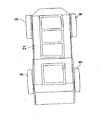
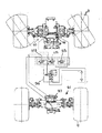
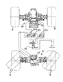
本発明の適用対象となる多目的作業車は、その平面図(図2)と側面図(図1)に示すように、モノコックフレームに左右の前輪8,8と左右の後輪9,9からなる走行装置10を操舵可能に支持し、一般的なトラクタの構成と前後を逆に、すなわち、エンジン6を機体後部に配置し、トランスミッション14を機体前部に配置する。その機体前部に操縦部2d、後部に荷台2tを構成し、かつ、作業機動力として機体前部にPTO軸13を備え、また、機体中間位置に車高検出機構2hを下垂状に構成する。
Next, specific embodiments of the present invention will be described with reference to the drawings.
As shown in the plan view (FIG. 2) and the side view (FIG. 1), the multipurpose work vehicle to which the present invention is applied is composed of left and right
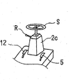
また、操縦部2dには、その要部斜視図を図3に示すように、ハンドルコラム2cを立設してステアリングハンドルSを設け、ハンドルコラム2cの左側部に前後進切換レバーR、ハンドルコラム2cの基部にはその右側位置にHSTペダル5、左側位置にブレーキペダル12等の操作手段をそれぞれ配置する。
Further, as shown in FIG. 3, the
トランスミッション14は、後に詳述するように、主変速機構としての静油圧式無段変速機構1、および副変速機構7を直列に内設して前後輪8,9とPTO出力軸13に駆動力を伝動する。前後進切換レバーRを操作してHSTペダル5を踏むと、エンジン6からの動力はトランスミッション14内の無段変速機構1で変速され、さらに、副変速機構7で変速されて、後輪9,9のみまたは、後輪9,9と前輪8,8の両方に伝達され、機体は前進または後進する。
As will be described in detail later, the
副変速機構7は、油圧クラッチ変速部11と機械式クラッチ変速部3Aから構成されている。
また、ブレーキペダル12を踏むと前輪8,8と後輪9,9のディスクブレーキ(図示せず)を作動させるとともに、HSTの可変油圧ポンプのトラニオン軸を中立に戻し、HSTの定量油圧モータからの出力を停止する。また、HSTペダル5とブレーキペダル12を同時に踏むとブレーキペダル12を優先する。
The auxiliary transmission mechanism 7 includes a hydraulic clutch transmission unit 11 and a mechanical clutch transmission unit 3A.
When the
PTO軸13には各種の作業機を接続して多目的作業を可能とする。例えば、路上清掃機を設けて路上清掃を行ったり、芝刈機を付けて芝刈作業を行ったり、除雪機を設けて除雪などの作業を行う。
Various work machines are connected to the
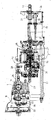
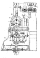
次に、ミッションケース14の内部構造を図4乃至図7で説明する。
ミッションケース14は、図4に示す如く、前ケース15、繋ぎケース16、中間ケース17、後ケース18の4つの中空ケースを連結した構成で、後ケース18に軸支した入力軸19にエンジン6の駆動力が入力し、この入力軸19の回転が後ケース18に内装されるインプットケース20内の増速ギア21,22を介して第一中継軸23へ伝動し、さらに増速ギア24,25で増速され、この増速ギア25に無段変速機構1の油圧入力軸38をスプライン嵌合している。
Next, the internal structure of the
As shown in FIG. 4, the
繋ぎケース16は従来の前ケース15と中間ケース17を連結してミッションケース14を長くするもので、前ケース15と中間ケース17及び後ケース18を従来のミッションケースと共用化することで製作コストを低く出来る。
The connecting
前記増速ギア21,22と増速ギア24,25を内装するインプットケース20は、高速走行を可能にするためにエンジン6の出力回転を増速するために設けるもので、従来のトラクタのミッションケース14内に伝動機構を収納可能にしている。このインプットケース20は図6に示す如く、密封ケースにしてミッションケース14の外部へ通じる給油管からオイルを給油するようにすれば、増速ギア21,22,24,25の修理の際にミッションケース14内のオイルを抜かずにインプットケース20のみを取り外せるので、作業が楽になる。
The
無段変速機構1の内部では油圧変速により出力を大きく無段階で変速して、PTO駆動軸26と走行駆動軸27の二つの軸へ出力する。
PTO駆動軸26にはPTOギア軸28を連結し、このPTOギア軸28のギア29と第二中継軸30に遊嵌したギア31を噛み合わせ、このギア31をPTO軸32に装着したPTOクラッチ34のギア33に噛み合わせている。PTOクラッチ34はギア33からPTO軸32への回転伝動を断続する。
Inside the continuously
A
PTO軸32にはPTO延長軸35を連結し、このPTO延長軸35のギア36をPTO出力軸13にスプライン嵌合したクラッチギア37に噛み合わせてPTO出力軸13を駆動している(図4参照)。
A PTO extension shaft 35 is connected to the PTO shaft 32, and a
PTOクラッチ34の詳細を図7に示しているが、クラッチ入ではクラッチ盤88が繋がってケーシング86が回転して伝動するが、クラッチ切では戻しバネ87の圧でクラッチ盤88が離れてケーシング86をフリーにする。この時にケーシング86の付き回りを防ぐ為に繋ぎケース16のボス部81に当接する係止リング85をケーシング86の外周に装着している。
7 shows details of the
走行駆動軸27には第三中継軸39を連結し、この第三中継軸39に固着したギア40ヘギア41,42を噛み合わせて第四中継軸43に伝動する。第四中継軸43にはメインギア軸44を連結している。
A
メインギア軸44には、大ギア45と中ギア46を一体的に固着し、このメインギア軸44の延長上にサブギア軸47を独立して回転可能に軸支している。このサブギア軸47には小ギア48と大ギア74及び走行伝動ギア75を一体的に固着している。従って、大ギア45と中ギア46は同一回転をし、小ギア48と大ギア74は後述するクラッチギア77からの回転を受ける(図7参照)。
A
大ギア45はクラッチ軸49に装着した高速油圧クラッチ51のギア50と噛み合い、中ギア46はクラッチ軸49に装着した低速油圧クラッチ52のギア53と噛み合い、メインギア軸44の回転をクラッチ軸49へ高速或いは低速で伝動する。
The
クラッチ軸49の延長上にスプライン軸76をスプライン嵌合し、このスプライン軸76にクラッチギア77をスプライン嵌合して、クラッチ軸49の回転をクラッチギア77に伝動している。また、クラッチ軸49を支持する繋ぎケース16のボス部81にはクラッチ軸49の油圧孔に通じる油圧用孔82,83,84を設けて、高速油圧クラッチ51と低速油圧クラッチ52に作動油を送るようにしている。
A
クラッチギア77には大ギア78と小ギア73を形成する2段ギアに設け、大ギア78が前記サブギア軸47の小ギア48に噛み合って増速伝動して高速ギアクラッチ3aを構成したり、小ギア79がサブギア軸47の大ギア74に噛み合って減速伝動して低速ギアクラッチ3bを構成したり、大ギア78と小ギア73が共に遊転して動力切になるようにして高低ギア変速クラッチ3を構成している。
The clutch gear 77 is provided in a two-stage gear that forms a large gear 78 and a small gear 73, and the large gear 78 meshes with the small gear 48 of the sub-gear shaft 47 to increase the transmission speed to constitute the high-speed gear clutch 3a. The small gear 79 meshes with the
サブギア軸47の走行伝動ギア75は、スプライン軸76に遊嵌したドライブピニオン軸62にスプライン嵌合した走行ギア56に噛み合ってドライブピニオン軸62を駆動している。ドライブピニオン軸62のドライブピニオン63が前輪8の車軸へ装着した図外デフ機構のベベルギアへ駆動力を伝動するのである。
The travel transmission gear 75 of the sub gear shaft 47 is engaged with the travel gear 56 that is spline-fitted to the
ドライブピニオン軸62は、高速油圧クラッチ51からクラッチギア77の大ギア78とサブギア軸47の小ギア48への伝動による第四速か、高速油圧クラッチ51からクラッチギア77の小ギア73とサブギア軸47の大ギア74への伝動による第三速か、低速油圧クラッチ52からクラッチギア77の大ギア78とサブギア軸47の小ギア48への伝動による第二速か、低速油圧クラッチ52からクラッチギア77の小ギア73とサブギア軸47の大ギア74への伝動による第一速かのどれかで回転することになる。
The
高速油圧クラッチ51と低速油圧クラッチ52と高低ギア変速クラッチ3を副変速機構7という。
また、ドライブピニオン軸62の回転は、走行ギア56からPTO軸32に装着した大小ギア59の小ギア部57へ伝動し、さらに大ギア部58に噛み合う後輪駆動軸61のクラッチギア60で適宜に後輪9へ駆動力を伝動可能にしている。
The high speed hydraulic clutch 51, the low speed hydraulic clutch 52, and the high / low
Further, the rotation of the
走行ギア56は、ベベルギア軸62に伝動すると共に大小ギア59を介して後輪駆動軸61へ伝動しているので、伝動構成を単純化して前後に長くなるのを防いでいる。
尚、高速油圧クラッチ51と低速油圧クラッチ52はコントローラからの制御信号によりソレノイドを介してどちらかを入に保持するのであるが、ブレーキペダル12の踏み込みを検出するスイッチを設けて、このスイッチの踏込み信号で高速油圧クラッチ51と低速油圧クラッチ52のソレノイドへの電力を断って両クラッチ51,52をニュートラルにするようにしている。このニュートラルの状態でブレーキを作用することで素早く停止でき、ギア変速クラッチ3の切換えがスムーズに行える。
Since the traveling gear 56 is transmitted to the
Note that either the high-speed hydraulic clutch 51 or the low-speed
図8は、変速レバー4を示し、変速溝65を中央のニュートラル位置Nから前後位置H,Lに回動することで、前記の機械式クラッチ変速部3Aのギア変速クラッチ3を高速ギアクラッチ3aが入り状態、又は低速ギアクラッチ3bが入り状態に変速する。この変速レバー4のグリップ66の頭部に設ける増速ボタン67を押すと、油圧クラッチ変速部11の高速油圧クラッチ51を入り動作し、減速ボタン68を押すと低速油圧クラッチ52を入り動作する。
FIG. 8 shows the speed change lever 4, and the
また、変速溝65には変速レバー4の位置を検出するセンサ70H,Lを設けて、変速レバー4が低速位置Lから高速位置Hに移動すると高速油圧クラッチ51が入であっても切にして、低速油圧クラッチ52が入になって第三速になり、高速位置Hから低速位置Lに移動すると低速油圧クラッチ52が入であっても切にして、高速油圧クラッチ51が入になって第二速になるよう変速制御を行っている。
Further, sensors 70H and L for detecting the position of the speed change lever 4 are provided in the
なお、高速油圧クラッチ51を入りにする場合には、HSTペダル5が3/4以上踏込まれて無段変速機構1が高速であれば一旦低速にして変速ショックを低減させる。また、変速レバー4が低速位置Lで滅速ボタン73を押すと第一速になり、変速レバー4が高速位置Hで増速ボタン72を押すと第四速になる。
When the high-speed
前記のように、無段変速機構1と、機械式クラッチ変速部3A及び油圧クラッチ変速部11からなる副変速機構7とを備えることによって、副変速機構として機械式クラッチ変速部のみの構成であった従来技術の欠点を解消するものである。従来技術では、機体停止時に事前に車速を選択してから登坂におよぶため、登坂を開始してからさらに登坂力が必要となっても一旦平地に戻ってから変速しないと、機体が停止して、平地でギヤに負荷がかからない状況でないと変速できない不都合がある。また作業時は兎も角、路上走行で最高速に走行中坂に差し掛かった場合、変速が必要でも一旦平地に戻らねばならないことは、公道においては後続車との関係で極めて危険である。さらに公道走行中に最高速を高く設定した場合、最初からトルクの低い高速ギヤで発進すると、最高速に至るまでの距離が長くなり非現実的となっていた。本実施例のように、副変速機構7を機械式クラッチ変速部3Aと油圧クラッチ変速部11によって構成することにより、走行中の油圧クラッチ変速部11操作が可能としたため、上記の決定を解消し、傾斜地走行や公道での走行の操作性を向上する。
As described above, the continuously
図9は、マイクロコンピュータ100による走行変速制御の制御ブロック図である。
マイクロコンピュータ100へ入力インターフェース101を介して入力するデータ信号は、ペダルポジションセンサ103によるHSTペダル5の踏込み位置信号と、HSTトラニオンポジションセンサ104からの無段変速機構1の変速を行うトラニオン軸の回動位置信号と、シャトル前進スイッチ105とシャトル後進スイッチ106による前後進切換レバーRの前後進位置信号と、増速ボタン67と減速ボタン68による油圧クラッチ変速部11の高速、低速切換信号と、変速レバーLスイッチ70Lと変速レバーHスイッチ70Hによる変速レバー4の高低切換信号と、車速センサ111による走行速度信号と、エンジン回転センサ109からのエンジン回転信号と、モータ電流センサ110からのトラニオン軸を駆動するモータの電流値である。
FIG. 9 is a control block diagram of travel shift control by the
The data signal input to the
制御部100から出力インターフェース102を介して出力する制御信号は、無段変速機構1のトラニオン軸を駆動するモータを作動するHSTトラニオン正転リレー112に対する正転信号とHSTトラニオン逆転リレー113に対する逆転信号とHSTトラニオン駆動リレー114に対する駆動信号と、一速切換ソレノイド115と二速切換ソレノイド116に対する変速切換信号と、クラッチ圧設定ソレノイド117に対する高速油圧クラッチ51と低速油圧クラッチ52の作動圧信号と、4WS切換ソレノイドA118と4WS切換ソレノイドB119と4WS切換ソレノイドC120に対する切換信号である。
The control signal output from the
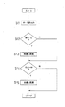
図10は、前後進切換レバーRの中立への操作による自動制御のフローチャートで、ステップS1でデータを読込み、ステップS2で前後進切換レバーRが中立かの判定を行い、この判定がYESであればステップS3で無段変速機構1を中立にしてステップS4で一定時間(2乃至3秒)経過したかの判定を行い、この判定がYESであればステップS5で油圧クラッチ(高速油圧クラッチ51と低速油圧クラッチ52)を中立にしてリターンする。ステップS2とステップS4の判定がNOであればそのままでリターンする。
FIG. 10 is a flowchart of automatic control by the operation to the neutral position of the forward / reverse switching lever R. In step S1, data is read, and it is determined whether the forward / reverse switching lever R is neutral in step S2, and this determination is YES. For example, in step S3, the continuously
図11は、変速レバー4の変速制限制御のフローチャートで、ステップS11でデータを読込み、ステップS12で変速レバー4を中立から低速(L)に操作したかの判定を行い、YESであればステップS13で副変速機構7を第二速(H2)に変速する。この判定がNOであればステップS13の処理をパスする。さらに、変速レバー4を中立から高速(H)に操作したかの判定を行い、YESであればステップS15で副変速機構7を第三速(H1)に変速する。この判定がNOであればステップS15の処理をパスする。 FIG. 11 is a flowchart of the shift limit control of the shift lever 4. In step S11, data is read, and it is determined whether the shift lever 4 is operated from neutral to low speed (L) in step S12. If YES, step S13 is performed. To shift the auxiliary transmission mechanism 7 to the second speed (H2). If this determination is NO, the process of step S13 is passed. Further, it is determined whether the speed change lever 4 has been operated from neutral to high speed (H). If YES, the subtransmission mechanism 7 is shifted to the third speed (H1) in step S15. If this determination is NO, the process of step S15 is passed.
次いで、旋回モードについて説明する。
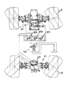
ステアリングハンドルS操作に応じて前輪8,8を操舵する前輪操舵装置90と、前記前輪8,8から独立して後輪9,9を操舵する後輪操舵装置91と、オペレータにより操作される操舵モード選択手段としてのセレクトスイッチ92と、このセレクトスイッチ92の操作状態に基づいて、前輪操舵モードFWS、後輪操舵モードRWS、及び前記前輪8,8及び後輪9,9を操舵する四輪操舵モード4WSを備えている。即ち、ステアリングハンドルSの操作に基づき操舵油圧回路94からの圧油が3連のソレノイドバルブ95a,95b,95cに供給される。これら3連の第1〜第3ソレノイドバルブ95a,95b,95cは、2位置切替バルブ形態に設けられ、ソレノイドのオン,オフ組合せによって、上記前輪操舵モードFWS、後輪操舵モードRWS、及び前記前輪8,8及び後輪9,9を操舵する四輪操舵モード4WSに設定される構成である。例えば、図12に示す構成は前輪操舵モードFWSであり、第1ソレノイドバルブ95a〜第3ソレノイドバルブ95bはオフに設定されている。また、後輪操舵モードRWS(図13)では、第1、3ソレノイドバルブ95a,95cがオン、第2ソレノイドバルブ95bはオフに設定される。また、四輪操舵モード4WS(図14)では、第1、2ソレノイドバルブ95a,95bがオン、第3ソレノイドバルブ95cはオフに設定される。なお、四輪操舵モード4WSとして本実施例では前後輪は逆位相となって小回り旋回に有利な構成を採用しているが、同位相モードとしてもよい。96は前輪用操舵シリンダ、97は後輪用操舵シリンダで、前記第1〜第3のソレノイドバルブ95a〜95cの油路切り替えに伴い圧油の供給を受け左右に操舵できる構成である。
Next, the turning mode will be described.
A front
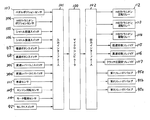
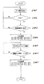
上記構成において、各操舵モードへの移行の手順について、図15〜図17のフローチャートに基づき説明する。キースイッチ操作直後は前輪操舵モードFWSに切り替る(ステップ102,ステップ105)が、この前輪操舵モードFWSには、操舵モード選択手段92としてのセレクトスイッチ92の操作で切り替る(ステップ104〜ステップ105)。
In the above configuration, the procedure for shifting to each steering mode will be described with reference to the flowcharts of FIGS. Immediately after the key switch operation, the front wheel steering mode FWS is switched to (step 102, step 105), but this front wheel steering mode FWS is switched by the operation of the select switch 92 as the steering mode selection means 92 (
なお、所定の条件が整っておれば、セレクトスイッチ92を押すごとに、操舵モードは、前輪操舵→後輪操舵→4輪操舵→前輪操舵・・・の順に繰り返される構成としている。
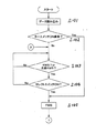
前輪操舵モードFWSから後輪操舵モードRWSの移行については、図16のフローチャートに従う。即ち、ステップ202で前輪操舵モードと判定され、セレクトスイッチ92がオンすると(ステップ203)、車速が検出される。車速が所定車速未満(実施例では略0としている)であるか否か判定され(ステップ204)、車速なし検出されると副変速機構7の変速位置が判定される(ステップ205,206)。機械式クラッチ変速部3Aと油圧クラッチ変速部11の組合せ変速位置が第一速から第三速までの間にあるときは、ステップ207に進んで後輪駆動(RWS)に切り替る。
If predetermined conditions are satisfied, the steering mode is repeated in the order of front wheel steering → rear wheel steering → four wheel steering → front wheel steering each time the select switch 92 is pressed.
The transition from the front wheel steering mode FWS to the rear wheel steering mode RWS follows the flowchart of FIG. That is, when it is determined in step 202 that the front wheel steering mode is selected and the select switch 92 is turned on (step 203), the vehicle speed is detected. It is determined whether or not the vehicle speed is less than a predetermined vehicle speed (substantially 0 in the embodiment) (step 204). If no vehicle speed is detected, the shift position of the subtransmission mechanism 7 is determined (
上記ステップ206で、油圧クラッチ変速部11が高速側に変速されたとき(第四速)には、前輪操舵モードFWSに移行する(上例は、前輪操舵モードFWSを継続する)。
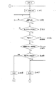
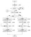
さらに、後輪操舵モードRWSから四輪操舵モード4WSへの移行について、図17に基づき説明する。即ち、ステップ302で前輪操舵モードと判定され、セレクトスイッチ92がオンすると(ステップ303)、車速が検出される。車速が所定車速未満(実施例では略0としている)であるか否か判定され(ステップ304)、車速なし検出されると副変速機構7の変速位置が判定される(ステップ305,306)。機械式クラッチ変速部3Aと油圧クラッチ変速部11の組合せ変速位置が第一速から第三速までの間にあるときは、ステップ307に進んで後輪駆動(RWS)に切り替る。
When the hydraulic clutch transmission unit 11 is shifted to the high speed side in step 206 (fourth speed), the process shifts to the front wheel steering mode FWS (in the above example, the front wheel steering mode FWS is continued).
Furthermore, the transition from the rear wheel steering mode RWS to the four wheel steering mode 4WS will be described with reference to FIG. That is, when it is determined in
前記図16におけるステップ206と同様に、上記ステップ306で、油圧クラッチ変速部11が高速側に操作されたとき(第四速)には、前輪操舵モードFWSに移行する。
ところで、図16のステップ204、図17のステップ304において、車速が略0の範疇にないとき、つまり所定速度以上を検出するときには、変速を牽制され、特に、油圧クラッチ変速部11が低速から高速に切り替ることを牽制する構成である。つまり、この車速条件下(所定以上の車速検出)では、小旋回側への旋回モード変更を牽制する上、高速側への変速を牽制して安全を確保するものである。
As in step 206 in FIG. 16, when the hydraulic clutch transmission unit 11 is operated to the high speed side (fourth speed) in
Meanwhile, in
なお、ステップ103における点滅4WDは、四輪操舵モード作動中を表示する表示部の点滅状態を示し、広義に四輪操舵モードを意図するものである。ステップ202、ステップ302の夫々点滅FWS,点滅RWSも同様の意味である。
The blinking 4WD in
また、ステップ204、304に於ける「車速≒0」は極低速の所定車速を意図するものであり、0車速を含むものである。
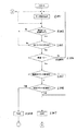
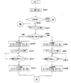
図18〜図20は、前後輪のズレ補正に関するフローチャートを示すものである。図18は、前輪操舵モードFWSのとき、操舵角が元々中立位置にあるべき後輪9の操舵角が中立範囲から逸脱すると検出された場合の措置について示すものである。後輪操舵角が中立範囲±α以上と判定されると(ステップ403)、後輪操舵モードRWSに設定変更される(ステップ404)。この状態でステアリングハンドルS操作し、後輪9が中立範囲内に収まると(ステップ405、406)、前輪操舵モードFWSに復帰させる(ステップ407)。こうして後輪の操舵角を制御部に更新することによって車輪のズレを修正できる。
Further, “vehicle speed≈0” in
18 to 20 are flowcharts relating to the correction of the displacement between the front and rear wheels. FIG. 18 shows measures taken when it is detected that the steering angle of the
上記の要領で、後輪操舵モードRWS時に前輪8の操舵角が中立位置からずれるときには前輪操舵モードに設定しておき前輪のズレ補正を行うことができる。
図19,20は、四輪操舵モード4WS中のズレ補正に関するもので、このうち図19は前後輪の操舵角検出に基づきずれ判定が確認され(ステップ502)、かつその状態が逆位相であるときのズレ補正を示す。ステアリングハンドルS操作に基づき、前輪8、後輪9のいずれが早く中立範囲内に入るかを判定し(ステップ504)、前輪8が中立範囲内になったときには後輪操舵モードRWSに設定し(ステップ505)、ステアリングハンドルS操作によって後輪9が中立範囲になったか否かを判断し(ステップ507)、このときの操舵角を中立相当に更新する。次いで四輪操舵モード4WSに戻す(ステップ508)。
In the above manner, when the steering angle of the
19 and 20 relate to deviation correction during the four-wheel steering mode 4WS. Of these, FIG. 19 confirms the deviation based on the detection of the steering angle of the front and rear wheels (step 502), and the state is in reverse phase. The deviation correction is shown. Based on the operation of the steering wheel S, it is determined which of the
図20は、ステップ502相当の判定にて同位相であるときのズレ補正を示す。ステップ604で中立位置から離れていく側の車輪が前輪8か後輪9かで操舵モードを決定する。つまり後輪9が離れるときには前輪操舵モードFWSに設定し、ステアリングハンドルS操作により中立範囲内になると四輪操舵モード4WSに復帰させる(ステップ606〜608)。そして前輪8の中立位置を更新する。後輪が離れる場合も同様である(ステップ609〜612)。
FIG. 20 shows misalignment correction when the phase corresponding to step 502 is the same phase. In step 604, the steering mode is determined based on whether the wheel on the side away from the neutral position is the
ステップ608又はステップ612まで実行すると、次いで図19の逆位相におけるズレ補正モードを実行する。こうして四輪操舵モード4WS中の車輪のズレ補正を行うことができる。 When step 608 or step 612 is executed, the shift correction mode in the opposite phase of FIG. 19 is then executed. In this way, it is possible to correct the deviation of the wheels during the four-wheel steering mode 4WS.
1 無段変速機構(主変速機構)
6 エンジン
7 副変速機構
8 前輪
9 後輪
11 油圧クラッチ変速部
90 前輪操舵装置
91 後輪操舵装置
92 セレクトスイッチ(操舵モード選択手段)
S ステアリングハンドル
FWS 前輪操舵モード
RWS 後輪操舵モード
4WS 四輪操舵モード
1 Continuously variable transmission mechanism (main transmission mechanism)
6 Engine 7
S Steering handle FWS Front wheel steering mode RWS Rear wheel steering mode 4WS Four wheel steering mode
Claims (1)
Priority Applications (2)
| Application Number | Priority Date | Filing Date | Title |
|---|---|---|---|
| JP2008088785A JP2009241663A (en) | 2008-03-28 | 2008-03-28 | Working vehicle |
| DE102009000452.1A DE102009000452B4 (en) | 2008-03-28 | 2009-01-28 | working vehicle |
Applications Claiming Priority (1)
| Application Number | Priority Date | Filing Date | Title |
|---|---|---|---|
| JP2008088785A JP2009241663A (en) | 2008-03-28 | 2008-03-28 | Working vehicle |
Publications (1)
| Publication Number | Publication Date |
|---|---|
| JP2009241663A true JP2009241663A (en) | 2009-10-22 |
Family
ID=41254117
Family Applications (1)
| Application Number | Title | Priority Date | Filing Date |
|---|---|---|---|
| JP2008088785A Pending JP2009241663A (en) | 2008-03-28 | 2008-03-28 | Working vehicle |
Country Status (2)
| Country | Link |
|---|---|
| JP (1) | JP2009241663A (en) |
| DE (1) | DE102009000452B4 (en) |
Cited By (6)
| Publication number | Priority date | Publication date | Assignee | Title |
|---|---|---|---|---|
| JP2012183950A (en) * | 2011-03-07 | 2012-09-27 | Furukawa Electric Co Ltd:The | Starting possibility determination apparatus, and starting possibility determination method |
| CN103640623A (en) * | 2013-12-24 | 2014-03-19 | 威海广泰空港设备股份有限公司 | High-speed four-wheel steering stabilizing device of vehicle and control method of high-speed four-wheel steering stabilizing device |
| JP2017141892A (en) * | 2016-02-10 | 2017-08-17 | 株式会社丸山製作所 | vehicle |
| US10227000B1 (en) | 2010-06-15 | 2019-03-12 | Hydro-Gear Limited Partnership | Selectable four-wheel drive system |
| JP2024004977A (en) * | 2022-06-29 | 2024-01-17 | 井関農機株式会社 | work equipment |
| WO2024203530A1 (en) * | 2023-03-24 | 2024-10-03 | 株式会社クボタ | Work vehicle |
Families Citing this family (2)
| Publication number | Priority date | Publication date | Assignee | Title |
|---|---|---|---|---|
| AT14396U1 (en) * | 2013-09-13 | 2015-10-15 | Lindner Traktorenwerk Gmbh | standard tractor |
| KR20240177433A (en) * | 2023-06-20 | 2024-12-27 | 현대모비스 주식회사 | Apparatus and method for controlling of 4wheel independent steering system |
Family Cites Families (5)
| Publication number | Priority date | Publication date | Assignee | Title |
|---|---|---|---|---|
| US5111901A (en) * | 1989-08-08 | 1992-05-12 | Oshkosh Truck Company | All wheel steering system |
| DE4334279A1 (en) * | 1993-10-08 | 1995-04-13 | Claas Ohg | All-wheel steering control system |
| IT1296535B1 (en) * | 1997-09-29 | 1999-07-02 | Fki Fai Komatsu Ind Spa | ELECTRONIC CONTROL DEVICE FOR THE MANAGEMENT OF THE STEERING IN EARTH-MOVING MACHINES. |
| JP2000053016A (en) | 1998-08-04 | 2000-02-22 | Kioritz Corp | Four-wheel steering work vehicle |
| DE102005019487B4 (en) * | 2005-04-27 | 2009-02-05 | Audi Ag | Passenger cars comprising independently steerable front and rear wheels |
-
2008
- 2008-03-28 JP JP2008088785A patent/JP2009241663A/en active Pending
-
2009
- 2009-01-28 DE DE102009000452.1A patent/DE102009000452B4/en not_active Expired - Fee Related
Cited By (10)
| Publication number | Priority date | Publication date | Assignee | Title |
|---|---|---|---|---|
| US10227000B1 (en) | 2010-06-15 | 2019-03-12 | Hydro-Gear Limited Partnership | Selectable four-wheel drive system |
| JP2012183950A (en) * | 2011-03-07 | 2012-09-27 | Furukawa Electric Co Ltd:The | Starting possibility determination apparatus, and starting possibility determination method |
| US8949007B2 (en) | 2011-03-07 | 2015-02-03 | Furukawa Electric Co., Ltd. | Start-up possibility determining apparatus and start-up possibility determining method |
| CN103640623A (en) * | 2013-12-24 | 2014-03-19 | 威海广泰空港设备股份有限公司 | High-speed four-wheel steering stabilizing device of vehicle and control method of high-speed four-wheel steering stabilizing device |
| CN103640623B (en) * | 2013-12-24 | 2016-11-16 | 威海广泰空港设备股份有限公司 | Vehicle high-speed four-wheel steering stabilising arrangement and control method thereof |
| JP2017141892A (en) * | 2016-02-10 | 2017-08-17 | 株式会社丸山製作所 | vehicle |
| JP2024004977A (en) * | 2022-06-29 | 2024-01-17 | 井関農機株式会社 | work equipment |
| JP7845086B2 (en) | 2022-06-29 | 2026-04-14 | 井関農機株式会社 | Work equipment |
| WO2024203530A1 (en) * | 2023-03-24 | 2024-10-03 | 株式会社クボタ | Work vehicle |
| JP2024137113A (en) * | 2023-03-24 | 2024-10-07 | 株式会社クボタ | Work vehicle |
Also Published As
| Publication number | Publication date |
|---|---|
| DE102009000452A1 (en) | 2009-12-03 |
| DE102009000452B4 (en) | 2015-07-09 |
Similar Documents
| Publication | Publication Date | Title |
|---|---|---|
| JP2009241663A (en) | Working vehicle | |
| JP4928239B2 (en) | Work vehicle | |
| JP5797499B2 (en) | Agricultural tractor | |
| JP5003311B2 (en) | Work vehicle | |
| EP3305626B1 (en) | Work vehicle | |
| JP2010078089A (en) | Continuously variable running controlling device for working vehicle | |
| JP2009180232A (en) | Continuously variable work vehicle | |
| JP2009138895A (en) | Traveling vehicle | |
| JP6002899B2 (en) | Travel control device for work vehicle | |
| JP5228538B2 (en) | Work vehicle | |
| JP6127940B2 (en) | Work vehicle | |
| JP6910970B2 (en) | Control device for work vehicles | |
| JP2009083612A (en) | Work vehicle | |
| JP5125387B2 (en) | Shift control device for work vehicle | |
| JP5181772B2 (en) | Work vehicle | |
| JP3659594B2 (en) | Farm vehicle transmission | |
| JP2009209948A (en) | Working vehicle | |
| JP2009052609A (en) | Shift control device for work vehicle | |
| JP6487774B2 (en) | Work vehicle | |
| JP2008138755A (en) | Multipurpose work vehicle power transmission mechanism | |
| JP2009058031A (en) | Work vehicle | |
| JP2010078091A (en) | Shift controller of working vehicle | |
| JPH08216914A (en) | Steering control device for work vehicle | |
| JP3763270B2 (en) | Traveling device | |
| JPH05301580A (en) | Steering control device such as combine |