JP2009091087A - Guide rail supporting structure of elevator - Google Patents
Guide rail supporting structure of elevator Download PDFInfo
- Publication number
- JP2009091087A JP2009091087A JP2007262006A JP2007262006A JP2009091087A JP 2009091087 A JP2009091087 A JP 2009091087A JP 2007262006 A JP2007262006 A JP 2007262006A JP 2007262006 A JP2007262006 A JP 2007262006A JP 2009091087 A JP2009091087 A JP 2009091087A
- Authority
- JP
- Japan
- Prior art keywords
- guide rail
- car
- pair
- connecting member
- elevator
- Prior art date
- Legal status (The legal status is an assumption and is not a legal conclusion. Google has not performed a legal analysis and makes no representation as to the accuracy of the status listed.)
- Pending
Links
Images


Abstract
Description
本発明は、エレベータのガイドレール支持構造に関し、特に、ガイドレールの上端部が建物の壁や梁に固定されていない場合に適用することができるエレベータのガイドレール支持構造に関する。 The present invention relates to an elevator guide rail support structure, and more particularly to an elevator guide rail support structure that can be applied when the upper end of the guide rail is not fixed to a wall or beam of a building.
下記特許文献1に記載されているように、エレベータには、上下方向に延出する一対のかご用ガイドレールと、上下方向に延出する一対の重り用ガイドレールとが設けられている。エレベータの運行時には、乗りかごがかご用ガイドレールに沿って昇降し、つり合い重りが重り用ガイドレールに沿って昇降する。
As described in
かご用ガイドレール及び重り用ガイドレールは、上下方向に沿った複数箇所で建物の壁や梁に固定されており、上端部も建物の壁や梁に固定されている。
しかしながら、建物の構造やエレベータの構造によっては、かご用ガイドレールの上端部及び重り用ガイドレールの上端部を建物の壁や梁に固定することができず、これらのガイドレールの上端側が自由端となり、片持ち支持状態となる場合がある。しかも、これらのガイドレールが建物の壁又は梁に固定されている複数の固定箇所のうち、最上方の固定箇所が、乗りかごやつり合い重りの最上昇位置よりも下方に位置する場合がある。例えば、エレベータが建物の吹き抜け部分に設置されている場合等である。 However, depending on the structure of the building and the structure of the elevator, the upper end of the guide rail for the car and the upper end of the guide rail for the weight cannot be fixed to the wall or beam of the building. And can be in a cantilevered state. In addition, among the plurality of fixing points where these guide rails are fixed to the walls or beams of the building, the uppermost fixing point may be located below the highest rising position of the car or the balance weight. For example, this may be the case when an elevator is installed in an atrium part of a building.
このようなエレベータにおいては、地震発生時の振動の影響や通常運行時の荷重の作用により、ガイドレールの上端側の撓み量が大きくなる。特に、乗りかご又はつり合い重りがガイドレールの最上方の固定位置より上方に位置する場合に地震が発生すると、乗りかご又はつり合い重りの荷重がガイドレールの最上方の固定箇所より上方側の箇所に作用し、ガイドレールの上端側の撓み量がさらに大きくなる。しかも、乗りかごやつり合い重りの荷重は、地震の揺れに伴って一対のガイドレールに対して交互に作用するため、一方のガイドレールの撓み量が他方のガイドレールの撓み量より大きくなる。これにより、最上方の固定箇所より上方の箇所では一対のガイドレールの間隔が大きくなり、乗りかごやつり合い重りがガイドレールから外れて脱レールすることがありうる。 In such an elevator, the amount of deflection on the upper end side of the guide rail becomes large due to the influence of vibrations when an earthquake occurs and the action of loads during normal operation. In particular, when an earthquake occurs when the car or the balance weight is located above the uppermost fixed position of the guide rail, the load of the car or the counterweight is placed at a position above the uppermost fixed position of the guide rail. It acts, and the amount of bending of the upper end side of the guide rail is further increased. In addition, since the load of the car and the balance weight acts alternately on the pair of guide rails as the earthquake sways, the amount of bending of one guide rail is larger than the amount of bending of the other guide rail. Thereby, the space | interval of a pair of guide rail becomes large in the location above the uppermost fixed location, and a car and a balance weight may remove | deviate from a guide rail, and may derail.
本発明はこのような課題を解決するためになされたもので、その目的は、ガイドレールの上端部が建物の壁や梁に固定されていない場合であっても、地震発生時や通常運行時におけるガイドレールの上端側の撓みを抑え、一対のガイドレールの上端側の間隔が広がることにより発生する乗りかごや釣合い重りの脱レールを防止することである。 The present invention has been made to solve such a problem, and the purpose of the present invention is when an earthquake occurs or during normal operation even when the upper end of the guide rail is not fixed to the wall or beam of the building. Is to suppress the deflection of the upper end side of the guide rail and prevent the carriage and the counterweight from being removed due to the increase in the distance between the upper end sides of the pair of guide rails.
本発明の実施の形態に係る第1の特徴は、エレベータのガイドレール支持構造において、上下方向に配設され、乗りかごを昇降可能にガイドし、建物の壁又は梁に固定される最上方の固定箇所が前記乗りかごの最上昇位置よりも下方に位置する一対のかご用ガイドレールと、一対の前記かご用ガイドレールを、前記乗りかごの最上昇位置よりも上方の位置でつなぐ連結部材と、を備えることである。 The first feature according to the embodiment of the present invention is that in the guide rail support structure of the elevator, which is arranged in the vertical direction, guides the car so that it can be raised and lowered, and is fixed to the wall or beam of the building. A pair of car guide rails whose fixing points are located below the highest ascent position of the car; and a connecting member that connects the pair of car guide rails at a position above the highest ascent position of the car; Is.
本発明の実施の形態に係る第2の特徴は、エレベータのガイドレール支持構造において、上下方向に配設され、つり合い重りを昇降可能にガイドし、建物の壁又は梁に固定される最上方の固定箇所が前記つり合い重りの最上昇位置よりも下方に位置する一対の重り用ガイドレールと、一対の前記重り用ガイドレールを、前記つり合い重りの最上昇位置よりも上方の位置でつなぐ連結部材と、を備えることである。 The second feature according to the embodiment of the present invention is that the elevator guide rail support structure is arranged in the vertical direction, guides the counterweight so that it can be raised and lowered, and is fixed to the wall or beam of the building. A pair of weight guide rails whose fixing points are positioned below the highest rising position of the counterweight; and a connecting member that connects the pair of weight guide rails at a position higher than the highest position of the counterweight. Is.
本発明の実施の形態に係る第3の特徴は、エレベータのガイドレール支持構造において、上下方向に配設され、乗りかごを昇降可能にガイドし、建物の壁又は梁に固定される最上方の固定箇所が前記乗りかごの最上昇位置よりも下方に位置する一対のかご用ガイドレールと、上下方向に配設され、つり合い重りを昇降可能にガイドし、建物の壁又は梁に固定される最上方の固定箇所が前記つり合い重りの最上昇位置よりも下方に位置する一対の重り用ガイドレールと、一対の前記かご用ガイドレールを、前記乗りかごの最上昇位置よりも上方の位置でつなぐ第1連結部材と、一対の前記重り用ガイドレールを、前記つり合い重りの最上昇位置よりも上方の位置でつなぐ第2連結部材と、を備え、前記第1連結部材の一端と前記第2連結部材の一端とが連結されていることである。 The third feature of the embodiment of the present invention is that the elevator guide rail support structure is arranged in the vertical direction, guides the car so that it can be raised and lowered, and is fixed to the wall or beam of the building. A pair of car guide rails, which are fixed below the most elevated position of the car, are arranged in the up and down direction, guide the counterweight so that it can be raised and lowered, and are fixed to the walls or beams of the building. A pair of weight guide rails whose upper fixing points are located below the highest lifted position of the counterweight and a pair of car guide rails connected at a position higher than the highest lifted position of the car. 1 connection member, and a second connection member that connects the pair of weight guide rails at a position higher than the most elevated position of the counterweight, and one end of the first connection member and the second connection member of It is that in which the end is connected.
本発明によれば、乗りかごや釣合い重りがかご用ガイドレールや重り用ガイドレールから脱レールすることを防止することができる。 ADVANTAGE OF THE INVENTION According to this invention, it can prevent that a cage | basket | car or a counterweight derails from the guide rail for cars, or the guide rail for weights.
以下、本発明の実施の形態を図面を用いて説明する。 Hereinafter, embodiments of the present invention will be described with reference to the drawings.
(第1の実施の形態)
本発明の第1の実施の形態に係るエレベータは、建物の吹き抜け部に設置されるものである。また、この実施の形態では、2台のエレベータが隣り合って設置されている。エレベータのガイドレール支持構造は、図1に示すように、建物の壁面に沿って配設される一対のかご用ガイドレール1と、一対の重り用ガイドレール2とを備えている。一対のかご用ガイドレール1と一対の重り用ガイドレール2とは、それぞれ平行に対向し、上下方向に配設されている。
(First embodiment)
The elevator which concerns on the 1st Embodiment of this invention is installed in the atrium part of a building. In this embodiment, two elevators are installed next to each other. As shown in FIG. 1, the elevator guide rail support structure includes a pair of
かご用ガイドレール1と重り用ガイドレール2とには、長手方向に沿った位置に複数のレールブラケット3が固定され、これらのレールブラケット3が止め金具4により建物の梁5に固定されている。梁5は、建物の高さ方向に沿って複数設けられている。なお、かご用ガイドレール1の上端部及び重り用ガイドレール2の上端部は、複数の梁5のうちの最上位に位置する梁5よりも高い位置まで伸び出しており、かご用ガイドレール1の上端部及び重り用ガイドレール2の上端部は建物の壁や梁5に固定されていない。
A plurality of
一対のかご用ガイドレール1の間にはエレベータの乗りかご6が配置され、乗りかご6にはガイド装置7が設けられている。ガイド装置7は、かご用ガイドレール1に対して上下方向摺動可能に係合している。
An
かご用ガイドレール1が、最上方のレールブラケット3を介して最上方の梁5に固定された最上方の固定箇所は、乗りかご6の最上昇位置よりも下方に位置している。図2に示す左側の乗りかご6が最上昇位置に移動した状態を示しており、かご用ガイドレール1が建物の梁5に固定される最上方の固定箇所である最上方のレールブラケット3は、上側のガイド装置7より下方に位置している。
The uppermost fixing point where the
一対の重り用ガイドレール2の間にはつり合い重り8が配置され、つり合い重り8にはガイド装置(図示せず)が設けられている。このガイド装置は、重り用ガイドレール2に対して上下方向摺動可能に係合している。
A
重り用ガイドレール2が、レールブラケット3を介して梁5に固定された最上方の固定箇所は、つり合い重り8の最上昇位置よりも下方に位置している。
The uppermost fixing point where the
一方のかご用ガイドレール1の上端部には、水平方向に延出する連結部材である第1連結部材9の一端が連結され、他方のかご用ガイドレール1の上端部には、第1連結部材9の他端が連結されている。これにより、この第1連結部材9によって一対のかご用ガイドレール1の上端部がつながれている。なお、一対のかご用ガイドレール1が第1連結部材9によりつながれる位置は、かご用ガイドレール1の上端部に限る必要はなく、乗りかご6の最上昇位置(図2に示す左側の乗りかご6における上側のガイド装置7の位置)よりも上方の位置であればよい。かご用ガイドレール1の上端部への第1連結部材9の連結は、溶接又はボルト締めにより行われている。
One end of a first connecting
第1連結部材9は、地震発生時に一対のかご用ガイドレール1をつないた状態に維持できる強度を有すればよく、その形状は限定されない。第1連結部材9としては、H型、L型、フラット状、棒状、パイプ状の鋼材を用いることができる。
The
一方の重り用ガイドレール2の上端部には、水平方向に延出する連結部材である第2連結部材10の一端が連結され、他方の重り用ガイドレール2の上端部には第2連結部材10の他端が連結されている。これにより、この第2連結部材10によって一対の重り用ガイドレール2の上端部がつながれている。なお、一対の重り用ガイドレール2が第2連結部材10によりつながれる位置は、重り用ガイドレール2の上端部に限る必要はなく、つり合い重り8の最上昇位置よりも上方の位置であればよい。重り用ガイドレール2の上端部への第2連結部材10の連結は、溶接又はボルト締めにより行われている。
One end of a second connecting
第2連結部材10は、地震発生時に一対の重り用ガイドレール2をつないだ状態に維持できる強度を有すればよく、その形状は限定されない。第2連結部材10としては、第1連結部材9と同様に、H型、L型、フラット状、棒状、パイプ状の鋼材を用いることができる。
The
このような構成において、地震発生時におけるかご用ガイドレール1と重り用ガイドレール2との動きについて説明する。
In such a configuration, the movement of the
一対のかご用ガイドレール1は上端部が第1連結部材9によりつながれており、地震発生時には、一対のかご用ガイドレール1の上端側が同期して同じ方向に揺れ動く。このため、地震の振動を一対のかご用ガイドレール1で受けることになり、かご用ガイドレール1の耐震強度が向上する。
The upper ends of the pair of
さらに、一対のかご用ガイドレール1が同期して同じ方向に揺れ動くことにより、地震発生時における乗りかご6の位置が、梁5に対するかご用ガイドレール1の最上方の固定箇所より上方であっても、地震の揺れに伴って乗りかご6の荷重が一方のかご用ガイドレール1に大きく作用し、一方のかご用ガイドレール1の撓み量が他方のかご用ガイドレール1の撓み量より大きくなるということが発生しない。したがって、一対のかご用ガイドレール1の上端側の間隔が常に略一定に維持され、一対のかご用ガイドレール1の上端側の間隔が大きくなって乗りかご6がかご用ガイドレール1から脱レールすることが防止される。
Further, the pair of
重り用ガイドレール2においても、かご用ガイドレール1と同様のことが言える。即ち、一対の重り用ガイドレール2は上端部が第2連結部材10によりつながれており、地震発生時には、一対の重り用ガイドレール2の上端側が同期して同じ方向に揺れ動く。このため、地震の振動を一対の重り用ガイドレール2で受けることになり、重り用ガイドレール2の耐震強度が向上する。
The same can be said for the
さらに、一対の重り用ガイドレール2が同期して同じ方向に揺れ動くことにより、地震発生時におけるつり合い重り8の位置が、梁5に対する重り用ガイドレール2の最上方の固定箇所より上方であっても、地震の揺れに伴ってつり合い重り8の荷重が一方の重り用ガイドレール2に大きく作用し、一方の重り用ガイドレール2の撓み量が他方の重り用ガイドレール2の撓み量より大きくなるということが発生しない。したがって、一対の重り用ガイドレール2の上端側の間隔が常に略一定に維持され、一対の重り用ガイドレール2の上端側の間隔が大きくなってつり合い重り8が重り用ガイドレール2から脱レールすることが防止される。
Further, since the pair of
(第2の実施の形態)
本発明の第2の実施の形態に係るエレベータのガイドレール支持構造について、図3に基づいて説明する。なお、第2の実施の形態及びこれ以降の実施の形態において、先行して説明した実施の形態の構成要素と同じ構成要素には同じ符号を付け、重複する説明は省略する。
(Second Embodiment)
An elevator guide rail support structure according to a second embodiment of the present invention will be described with reference to FIG. Note that, in the second embodiment and subsequent embodiments, the same components as those of the previously described embodiments are denoted by the same reference numerals, and redundant descriptions are omitted.
第2の実施の形態に係るエレベータのガイドレール支持構造では、第1の実施の形態で説明したように、一対のかご用ガイドレール1の上端部が第1連結部材9によりつながれ、一対の重り用ガイドレール2の上端部が第2連結部材10によりつながれている。さらに、第1連結部材9の一端と第2連結部材10の一端とが連結され、連結された第1連結部材9と第2連結部材10とはL字形状となっている。第1連結部材9と第2連結部材10との連結は、溶接又はボルト締めにより行われている。
In the elevator guide rail support structure according to the second embodiment, as described in the first embodiment, the upper ends of the pair of
このような構成において、第1連結部材9の一端と第2連結部材10の一端とが連結されることにより、一対のかご用ガイドレール1と一対の重り用ガイドレール2とがつながれている。
In such a configuration, by connecting one end of the first connecting
このため、地震発生時には、一対のかご用ガイドレール1の上端側と一対の重り用ガイドレール2の上端側とが同期して同じ方向に揺れ動く。このため、地震の振動を一対のかご用ガイドレール1と一対の重り用ガイドレール2とで受けることになり、かご用ガイドレール1と重り用ガイドレール2との耐震強度が向上する。
For this reason, when an earthquake occurs, the upper end sides of the pair of
また、地震発生時には、第1の実施の形態において説明したように、一対のかご用ガイドレール1の上端側の間隔が常に略一定に維持され、及び、一対の重り用ガイドレール2の上端側の間隔が常に略一定に維持される。このため、かご用ガイドレール1からの乗りかご6の脱レール、及び、重り用ガイドレール2からのつり合い重り8の脱レールを防止することができる。
When an earthquake occurs, as described in the first embodiment, the distance between the upper end sides of the pair of
(第3の実施の形態)
本発明の第3の実施の形態に係るエレベータのガイドレール支持構造について、図4に基づいて説明する。
(Third embodiment)
An elevator guide rail support structure according to a third embodiment of the present invention will be described with reference to FIG.
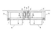
第3の実施の形態に係るエレベータのガイドレール支持構造では、第2の実施の形態で説明したように、第1連結部材9の一端と第2連結部材10の一端とが連結されている。さらに、第1連結部材9の他端に第3連結部材11の一端が連結され、第2連結部材10の他端に第3連結部材11の他端が連結されている。
In the elevator guide rail support structure according to the third embodiment, as described in the second embodiment, one end of the first connecting
第1連結部材9の他端への第3連結部材11の一端の連結、及び、第2連結部材10の他端への第3連結部材の他端の連結は、溶接又はボルト締めにより行われている。
The connection of one end of the
また、第3連結部材としては、第1連結部材9及び第2連結部材10と同様に、H型、L型、フラット状、棒状、パイプ状の鋼材を使用することができる。最上階の乗り場から見上げた場合の意匠性を考慮するのであれば、第3連結部材としてテンションロッドを使用することが好適である。
Moreover, as the 3rd connection member, similarly to the
このような構成において、第1連結部材9と第2連結部材10と第3連結部材11とは、三角形状のトラス構造を構成する。このため、第1連結部材9と第2連結部材10と第3連結部材11とからなるトラス構造により、地震発生時におけるかご用ガイドレール1と重り用ガイドレール2との撓みを抑えることができ、かご用ガイドレール1と重り用ガイドレール2との耐震強度を向上させることができる。
In such a configuration, the first connecting
また、第1の実施の形態において説明したように、地震発生時には、一対のかご用ガイドレール1の上端側の間隔が常に略一定に維持され、及び、一対の重り用ガイドレール2の上端側の間隔が常に略一定に維持される。このため、かご用ガイドレール1からの乗りかご6の脱レール、及び、重り用ガイドレール2からのつり合い重り8の脱レールを防止することができる。
Further, as described in the first embodiment, when an earthquake occurs, the distance between the upper end sides of the pair of
(第4の実施の形態)
本発明の第4の実施の形態に係るエレベータのガイドレール支持構造について、図5に基づいて説明する。
(Fourth embodiment)
An elevator guide rail support structure according to a fourth embodiment of the present invention will be described with reference to FIG.
第4の実施の形態に係るエレベータのガイドレール支持構造では、かご用ガイドレール1の上端部側の背面(乗りかご6に対向しない側の面)にバッキング材12が固定されている。かご用ガイドレール1の上端部に連結される第1連結部材9は、バッキング材12の上端部にも連結されている。バッキング材12に対する第1連結部材9の連結は、溶接又はボルト締めにより行われている。
In the elevator guide rail support structure according to the fourth embodiment, the
バッキング材12は、かご用ガイドレール1の強度を向上させるための部材であり、H型、L型、パイプ状等の鋼材であって、熱膨張係数がかご用ガイドレール1と略同じ材質のものが使用されている。
The
なお、重り用ガイドレール2の強度を向上させる場合には、重り用ガイドレール2の上端側の背面にバッキング材を固定する。この場合には、重り用ガイドレール2の上端部に連結される第2連結部材10を、バッキング材の上端部にも連結する。
In order to improve the strength of the
このような構成において、かご用ガイドレール1にバッキング材12が固定されることにより、かご用ガイドレール1の剛性を高めることができ、地震発生時や通常運行時におけるかご用ガイドレール1の撓み量を抑制することができる。
In such a configuration, the
同様に、重り用ガイドレール2にバッキング材が固定されることにより、重り用ガイドレール2の剛性を高めることができ、地震発生時や通常運行時における重り用ガイドレール2の撓み量を抑制することができる。
Similarly, by fixing the backing material to the
また、第1の実施の形態において説明したように、地震発生時には、一対のかご用ガイドレール1の上端側の間隔が常に略一定に維持され、及び、一対の重り用ガイドレール2の上端側の間隔が常に略一定に維持される。このため、かご用ガイドレール1からの乗りかご6の脱レール、及び、重り用ガイドレール2からのつり合い重り8の脱レールを防止することができる。
Further, as described in the first embodiment, when an earthquake occurs, the distance between the upper end sides of the pair of
(第5の実施の形態)
本発明の第5の実施の形態に係るエレベータのガイドレール支持構造について、図6に基づいて説明する。
(Fifth embodiment)
An elevator guide rail support structure according to a fifth embodiment of the present invention will be described with reference to FIG.
第5の実施の形態に係るエレベータのガイドレール支持構造では、かご用ガイドレール1の近傍に位置して、保持部材である立柱13が設けられている。立柱13は、レールブラケット3を介してかご用ガイドレール1が固定される梁5のうち、最上方に位置する梁5に固定され、上方に向けてかご用ガイドレール1の上端部と略同じ高さ位置まで延出されている。
In the elevator guide rail support structure according to the fifth embodiment, an
立柱13は、立柱13を設けない場合に最も大きな吊り下げ荷重が作用するかご用ガイドレール1の近傍、例えば、機械室レスエレベータにおける巻上機の荷重が作用するかご用ガイドレール1の近傍に設けることが好適である。
The
なお、立柱13は、必要に応じて他方のかご用ガイドレール1や重り用ガイドレール2の近傍に設けてもよく、全てのかご用ガイドレール1や重り用ガイドレール2の近傍に設けてもよい。
The
一対のかご用ガイドレール1の上端部と立柱13の上端部とには、第1連結部材9の端部側が固定されている。
The end portion side of the first connecting
さらに、この第5の実施の形態では、図3に示した第2の実施の形態と同様に、第1連結部材9の一端と、一対の重り用ガイドレール2の上端部を連結する第2連結部材10の一端とが連結されている。
Further, in the fifth embodiment, similarly to the second embodiment shown in FIG. 3, a second connecting the one end of the first connecting
このような構成において、立柱13が近傍に設けられたかご用ガイドレール1では、吊り下げ荷重により発生するモーメントをかご用ガイドレール1と立柱13とにより分散して支持することができ、かご用ガイドレール1の強度を向上させることができる。
In such a configuration, in the
地震発生時には、一対のかご用ガイドレール1の上端側と一対の重り用ガイドレール2の上端側と立柱13の上端側とが同期して同じ方向に揺れ動く。このため、地震の振動を一対のかご用ガイドレール1と一対の重り用ガイドレール2と立柱13とで受けることになり、かご用ガイドレール1と重り用ガイドレール2との耐震強度が向上する。
When an earthquake occurs, the upper end side of the pair of
また、第1の実施の形態において説明したように、地震発生時には、一対のかご用ガイドレール1の上端側の間隔が常に略一定に維持され、及び、一対の重り用ガイドレール2の上端側の間隔が常に略一定に維持される。このため、かご用ガイドレール1からの乗りかご6の脱レール、及び、重り用ガイドレール2からのつり合い重り8の脱レールを防止することができる。
Further, as described in the first embodiment, when an earthquake occurs, the distance between the upper end sides of the pair of
(第6の実施の形態)
本発明の第6の実施の形態に係るエレベータのガイドレール支持構造について、図7に基づいて説明する。
(Sixth embodiment)
An elevator guide rail support structure according to a sixth embodiment of the present invention will be described with reference to FIG.
第6の実施の形態に係るエレベータのガイドレール支持構造では、二以上のエレベータが隣り合って設けられている場合において、一方のエレベータに設けられた第1連結部材9と他方のエレベータに設けられた第1連結部材9とが連結されている。一つの第1連結部材9と他の第1連結部材9との連結は、溶接又は締付けボルトにより行われている。
In the elevator guide rail support structure according to the sixth embodiment, when two or more elevators are provided adjacent to each other, the
さらに、この第6の実施の形態では、図3に示した第2の実施の形態と同様に、それぞれのエレベータにおいて、第1連結部材9と第2連結部材10とが連結されている。
Further, in the sixth embodiment, the first connecting
このような構成において、隣り合って位置する二つのエレベータに一対ずつ設けられているかご用ガイドレール1は、第1連結部材9によりつながれている。このため、地震発生時には、二対のかご用ガイドレール1の上端側が同期して同じ方向に揺れ動き、地震の振動を二対のかご用ガイドレール1で受けることになり、かご用ガイドレール1の耐震強度が向上する。さらに、この第1連結部材9に対して、個々のエレベータに設けられている重り用ガイドレール2が連結されているため、二対のかご用ガイドレール1の上端側と二対の重り用ガイドレール2の上端側とが同期して同じ方向に揺れ動き、地震の振動を二対のかご用ガイドレール1と二対の重り用ガイドレール2とで受けることになり、重り用ガイドレール2の耐震強度も向上する。
In such a configuration, the
また、第1の実施の形態において説明したように、地震発生時には、各エレベータにおける一対のかご用ガイドレール1の上端側の間隔が常に略一定に維持され、及び、各エレベータにおける一対の重り用ガイドレール2の上端側の間隔が常に略一定に維持される。このため、かご用ガイドレール1からの乗りかご6の脱レール、及び、重り用ガイドレール2からのつり合い重り8の脱レールを防止することができる。
Further, as described in the first embodiment, when an earthquake occurs, the distance between the upper ends of the pair of
なお、第6の実施の形態では、2台のエレベータが隣り合って位置する場合において、それらのエレベータで用いられている第1連結部材9を連結した場合を例に挙げて説明したが、3台以上のエレベータが隣り合って位置する場合には、それらの各エレベータの第1連結部材9を連結するようにしてもよい。
In the sixth embodiment, when two elevators are located next to each other, the case where the first connecting
(第7の実施の形態)
本発明の第7の実施の形態に係るエレベータのガイドレール支持構造について、図8に基づいて説明する。
(Seventh embodiment)
An elevator guide rail support structure according to a seventh embodiment of the present invention will be described with reference to FIG.
第7の実施の形態に係るエレベータのガイドレール支持構造は、図7に示した第6の実施の形態で説明したように、隣り合うエレベータに設けられた第1連結部材9同士が連結されており、連結された第1連結部材9の両端部に引張部材であるテンションロッド14の一端が連結されている。テンションロッド14の他端は建物の壁15に連結されている。なお、第1連結部材9には第2連結部材10が連結されている。
In the elevator guide rail support structure according to the seventh embodiment, as described in the sixth embodiment shown in FIG. 7, the first connecting
テンションロッド14は、第1連結部材9に対して水平方向向き引張力を付与している。
The
このような構成において、かご用ガイドレール1及び重り用ガイドレール2の上端部が壁や梁などに固定されていないため、地震発生時にはかご用ガイドレール1及び重り用ガイドレール2に上下方向に作用する軸力が発生する。この軸力がかご用ガイドレール1及び重り用ガイドレール2を介してピットに伝わると、ピット床を破損する場合がある。
In such a configuration, since the upper ends of the
そこで、テンションロッド14を設け、第1連結部材9に対して水平向きの引張力を付与する。これにより、地震発生時におけるかご用ガイドレール1及び重り用ガイドレール2に作用する軸力を抑制することができ、軸力の作用によるピット床の破損を防止することができる。
Therefore, a
また、第1の実施の形態において説明したように、地震発生時には、各エレベータにおける一対のかご用ガイドレール1の上端側の間隔が常に略一定に維持され、及び、各エレベータにおける一対の重り用ガイドレール2の上端側の間隔が常に略一定に維持される。このため、かご用ガイドレール1からの乗りかご6の脱レール、及び、重り用ガイドレール2からのつり合い重り8の脱レールを防止することができる。
Further, as described in the first embodiment, when an earthquake occurs, the distance between the upper ends of the pair of
なお、この第7の実施の形態では、引張部材としてテンションロッド14を使用した場合を例に挙げて説明したが、引張部材としてテンションワイヤを用いてもよい。
In the seventh embodiment, the case where the
また、この第7の実施の形態では、第1連結部材9に対して付与する引張力を水平方向向きとした場合について説明したが、引張力を付与する方向としては、斜め上方向きであってもよい。
In the seventh embodiment, the case where the tensile force applied to the first connecting
1 かご用ガイドレール
2 重り用ガイドレール
5 梁
6 乗りかご
8 つり合い重り
9 第1連結部材(連結部材)
10 第2連結部材(連結部材)
11 第3連結部材
12 バッキング材
14 引張部材
15 壁
DESCRIPTION OF
10 Second connecting member (connecting member)
11 Third connecting
Claims (7)
一対の前記かご用ガイドレールを、前記乗りかごの最上昇位置よりも上方の位置でつなぐ連結部材と、
を備えることを特徴とするエレベータのガイドレール支持構造。 A pair of car guide rails that are arranged in the vertical direction, guide the car so that it can be raised and lowered, and the uppermost fixing part fixed to the wall or beam of the building is located below the highest ascent position of the car When,
A connecting member that connects a pair of the guide rails for the car at a position above the highest position of the car;
A guide rail support structure for an elevator, comprising:
一対の前記重り用ガイドレールを、前記つり合い重りの最上昇位置よりも上方の位置でつなぐ連結部材と、
を備えることを特徴とするエレベータのガイドレール支持構造。 A pair of weight guide rails that are arranged in the vertical direction, guide the counterweight so that it can be raised and lowered, and the uppermost fixed portion fixed to the wall or beam of the building is located below the highest position of the counterweight When,
A connecting member that connects the pair of weight guide rails at a position above the most elevated position of the counterweight;
A guide rail support structure for an elevator, comprising:
上下方向に配設され、つり合い重りを昇降可能にガイドし、建物の壁又は梁に固定される最上方の固定箇所が前記つり合い重りの最上昇位置よりも下方に位置する一対の重り用ガイドレールと、
一対の前記かご用ガイドレールを、前記乗りかごの最上昇位置よりも上方の位置でつなぐ第1連結部材と、
一対の前記重り用ガイドレールを、前記つり合い重りの最上昇位置よりも上方の位置でつなぐ第2連結部材と、
を備え、
前記第1連結部材の一端と前記第2連結部材の一端とが連結されていることを特徴とするエレベータのガイドレール支持構造。 A pair of car guide rails that are arranged in the vertical direction, guide the car so that it can be raised and lowered, and the uppermost fixing part fixed to the wall or beam of the building is located below the highest ascent position of the car When,
A pair of weight guide rails that are arranged in the vertical direction, guide the counterweight so that it can be raised and lowered, and the uppermost fixed portion fixed to the wall or beam of the building is located below the highest position of the counterweight When,
A first connecting member that connects a pair of the car guide rails at a position higher than the highest position of the car;
A second connecting member that connects the pair of weight guide rails at a position above the most elevated position of the counterweight;
With
An elevator guide rail support structure, wherein one end of the first connecting member and one end of the second connecting member are connected.
Priority Applications (2)
| Application Number | Priority Date | Filing Date | Title |
|---|---|---|---|
| JP2007262006A JP2009091087A (en) | 2007-10-05 | 2007-10-05 | Guide rail supporting structure of elevator |
| CN2008101684864A CN101402430B (en) | 2007-10-05 | 2008-09-28 | Guide rails support structure of elevator |
Applications Claiming Priority (1)
| Application Number | Priority Date | Filing Date | Title |
|---|---|---|---|
| JP2007262006A JP2009091087A (en) | 2007-10-05 | 2007-10-05 | Guide rail supporting structure of elevator |
Publications (1)
| Publication Number | Publication Date |
|---|---|
| JP2009091087A true JP2009091087A (en) | 2009-04-30 |
Family
ID=40536615
Family Applications (1)
| Application Number | Title | Priority Date | Filing Date |
|---|---|---|---|
| JP2007262006A Pending JP2009091087A (en) | 2007-10-05 | 2007-10-05 | Guide rail supporting structure of elevator |
Country Status (2)
| Country | Link |
|---|---|
| JP (1) | JP2009091087A (en) |
| CN (1) | CN101402430B (en) |
Families Citing this family (4)
| Publication number | Priority date | Publication date | Assignee | Title |
|---|---|---|---|---|
| CN104722997B (en) * | 2015-03-17 | 2016-04-06 | 江南嘉捷电梯股份有限公司 | Anti-positioning installation apparatus and the installation method of jumping onto the tracks of escalator |
| CN105253743B (en) * | 2015-10-29 | 2018-11-23 | 浙江西子重工机械有限公司 | It is a kind of can parallel running elevator |
| CN109556547A (en) * | 2018-11-22 | 2019-04-02 | 中国航空工业集团公司北京航空精密机械研究所 | A kind of composite guide rail structure and preparation method thereof for measuring machine |
| JP7004408B1 (en) * | 2020-08-17 | 2022-01-21 | 東芝エレベータ株式会社 | Rail unit |
Citations (5)
| Publication number | Priority date | Publication date | Assignee | Title |
|---|---|---|---|---|
| JPH02295876A (en) * | 1989-05-08 | 1990-12-06 | Mitsubishi Electric Corp | Elevator device |
| JPH1135249A (en) * | 1997-07-11 | 1999-02-09 | Taisei Corp | Elevator in base isolated building |
| JP2000007248A (en) * | 1998-06-17 | 2000-01-11 | Hitachi Ltd | Elevator |
| JP2006036450A (en) * | 2004-07-27 | 2006-02-09 | Toshiba Elevator Co Ltd | Elevator device |
| JP2006264862A (en) * | 2005-03-23 | 2006-10-05 | Toshiba Elevator Co Ltd | Elevator without machine room |
-
2007
- 2007-10-05 JP JP2007262006A patent/JP2009091087A/en active Pending
-
2008
- 2008-09-28 CN CN2008101684864A patent/CN101402430B/en not_active Expired - Fee Related
Patent Citations (5)
| Publication number | Priority date | Publication date | Assignee | Title |
|---|---|---|---|---|
| JPH02295876A (en) * | 1989-05-08 | 1990-12-06 | Mitsubishi Electric Corp | Elevator device |
| JPH1135249A (en) * | 1997-07-11 | 1999-02-09 | Taisei Corp | Elevator in base isolated building |
| JP2000007248A (en) * | 1998-06-17 | 2000-01-11 | Hitachi Ltd | Elevator |
| JP2006036450A (en) * | 2004-07-27 | 2006-02-09 | Toshiba Elevator Co Ltd | Elevator device |
| JP2006264862A (en) * | 2005-03-23 | 2006-10-05 | Toshiba Elevator Co Ltd | Elevator without machine room |
Also Published As
| Publication number | Publication date |
|---|---|
| CN101402430B (en) | 2011-04-13 |
| CN101402430A (en) | 2009-04-08 |
Similar Documents
| Publication | Publication Date | Title |
|---|---|---|
| JP2005162496A (en) | Counterweight and car of elevator | |
| JP2009091087A (en) | Guide rail supporting structure of elevator | |
| JP5329031B2 (en) | Elevator equipment | |
| JP4774429B2 (en) | Elevator equipment | |
| JP6058149B2 (en) | Elevator car | |
| JP5001013B2 (en) | Elevator equipment | |
| JP2011213420A (en) | Renewal method of hydraulic elevator and rope type elevator renewed by the method | |
| JP6714905B2 (en) | elevator | |
| JP4874672B2 (en) | Elevator equipment | |
| JP6658637B2 (en) | Rope runout suppression unit | |
| JP5692816B2 (en) | Elevator equipment | |
| JP5898057B2 (en) | Elevator load bearing beam holding device | |
| JP2006282368A (en) | Elevator device | |
| JP6218158B2 (en) | Machine room-less elevator | |
| JP5940713B1 (en) | Elevator compensatory support structure | |
| JP4056475B2 (en) | Elevator equipment | |
| JP5092407B2 (en) | Elevator equipment | |
| JP2013067492A (en) | Device for fixing hoisting machine of elevator | |
| WO2005077806A1 (en) | Elevator | |
| JP5963530B2 (en) | Elevator car | |
| JP6682054B2 (en) | Machine platform fixing device for elevator hoisting machine | |
| JP4554352B2 (en) | Elevator equipment | |
| JP2005212941A (en) | Coupling device for main cables of elevator | |
| CN103068712B (en) | Elevator device | |
| JP4342252B2 (en) | elevator |
Legal Events
| Date | Code | Title | Description |
|---|---|---|---|
| A621 | Written request for application examination |
Free format text: JAPANESE INTERMEDIATE CODE: A621 Effective date: 20100318 |
|
| A977 | Report on retrieval |
Effective date: 20120418 Free format text: JAPANESE INTERMEDIATE CODE: A971007 |
|
| A131 | Notification of reasons for refusal |
Effective date: 20120424 Free format text: JAPANESE INTERMEDIATE CODE: A131 |
|
| A02 | Decision of refusal |
Effective date: 20120814 Free format text: JAPANESE INTERMEDIATE CODE: A02 |