JP2008541064A - High-resolution tracking of industrial process materials using luminescent marker traces - Google Patents
High-resolution tracking of industrial process materials using luminescent marker traces Download PDFInfo
- Publication number
- JP2008541064A JP2008541064A JP2008510360A JP2008510360A JP2008541064A JP 2008541064 A JP2008541064 A JP 2008541064A JP 2008510360 A JP2008510360 A JP 2008510360A JP 2008510360 A JP2008510360 A JP 2008510360A JP 2008541064 A JP2008541064 A JP 2008541064A
- Authority
- JP
- Japan
- Prior art keywords
- luminescent
- industrial process
- materials
- light
- marker
- Prior art date
- Legal status (The legal status is an assumption and is not a legal conclusion. Google has not performed a legal analysis and makes no representation as to the accuracy of the status listed.)
- Withdrawn
Links
Images


Classifications
-
- G—PHYSICS
- G01—MEASURING; TESTING
- G01N—INVESTIGATING OR ANALYSING MATERIALS BY DETERMINING THEIR CHEMICAL OR PHYSICAL PROPERTIES
- G01N21/00—Investigating or analysing materials by the use of optical means, i.e. using sub-millimetre waves, infrared, visible or ultraviolet light
- G01N21/84—Systems specially adapted for particular applications
- G01N21/88—Investigating the presence of flaws or contamination
- G01N21/8806—Specially adapted optical and illumination features
-
- G—PHYSICS
- G01—MEASURING; TESTING
- G01N—INVESTIGATING OR ANALYSING MATERIALS BY DETERMINING THEIR CHEMICAL OR PHYSICAL PROPERTIES
- G01N21/00—Investigating or analysing materials by the use of optical means, i.e. using sub-millimetre waves, infrared, visible or ultraviolet light
- G01N21/62—Systems in which the material investigated is excited whereby it emits light or causes a change in wavelength of the incident light
- G01N21/63—Systems in which the material investigated is excited whereby it emits light or causes a change in wavelength of the incident light optically excited
- G01N21/64—Fluorescence; Phosphorescence
- G01N21/645—Specially adapted constructive features of fluorimeters
-
- G—PHYSICS
- G01—MEASURING; TESTING
- G01N—INVESTIGATING OR ANALYSING MATERIALS BY DETERMINING THEIR CHEMICAL OR PHYSICAL PROPERTIES
- G01N21/00—Investigating or analysing materials by the use of optical means, i.e. using sub-millimetre waves, infrared, visible or ultraviolet light
- G01N21/84—Systems specially adapted for particular applications
- G01N21/88—Investigating the presence of flaws or contamination
- G01N21/94—Investigating contamination, e.g. dust
-
- G—PHYSICS
- G06—COMPUTING; CALCULATING OR COUNTING
- G06K—GRAPHICAL DATA READING; PRESENTATION OF DATA; RECORD CARRIERS; HANDLING RECORD CARRIERS
- G06K19/00—Record carriers for use with machines and with at least a part designed to carry digital markings
- G06K19/06—Record carriers for use with machines and with at least a part designed to carry digital markings characterised by the kind of the digital marking, e.g. shape, nature, code
- G06K19/06009—Record carriers for use with machines and with at least a part designed to carry digital markings characterised by the kind of the digital marking, e.g. shape, nature, code with optically detectable marking
-
- G—PHYSICS
- G01—MEASURING; TESTING
- G01N—INVESTIGATING OR ANALYSING MATERIALS BY DETERMINING THEIR CHEMICAL OR PHYSICAL PROPERTIES
- G01N21/00—Investigating or analysing materials by the use of optical means, i.e. using sub-millimetre waves, infrared, visible or ultraviolet light
- G01N21/62—Systems in which the material investigated is excited whereby it emits light or causes a change in wavelength of the incident light
- G01N21/63—Systems in which the material investigated is excited whereby it emits light or causes a change in wavelength of the incident light optically excited
- G01N21/64—Fluorescence; Phosphorescence
- G01N21/6428—Measuring fluorescence of fluorescent products of reactions or of fluorochrome labelled reactive substances, e.g. measuring quenching effects, using measuring "optrodes"
- G01N2021/6439—Measuring fluorescence of fluorescent products of reactions or of fluorochrome labelled reactive substances, e.g. measuring quenching effects, using measuring "optrodes" with indicators, stains, dyes, tags, labels, marks
-
- G—PHYSICS
- G01—MEASURING; TESTING
- G01N—INVESTIGATING OR ANALYSING MATERIALS BY DETERMINING THEIR CHEMICAL OR PHYSICAL PROPERTIES
- G01N21/00—Investigating or analysing materials by the use of optical means, i.e. using sub-millimetre waves, infrared, visible or ultraviolet light
- G01N21/62—Systems in which the material investigated is excited whereby it emits light or causes a change in wavelength of the incident light
- G01N21/63—Systems in which the material investigated is excited whereby it emits light or causes a change in wavelength of the incident light optically excited
- G01N21/64—Fluorescence; Phosphorescence
- G01N21/645—Specially adapted constructive features of fluorimeters
- G01N2021/6463—Optics
-
- G—PHYSICS
- G01—MEASURING; TESTING
- G01N—INVESTIGATING OR ANALYSING MATERIALS BY DETERMINING THEIR CHEMICAL OR PHYSICAL PROPERTIES
- G01N2201/00—Features of devices classified in G01N21/00
- G01N2201/02—Mechanical
- G01N2201/022—Casings
- G01N2201/0221—Portable; cableless; compact; hand-held
-
- G—PHYSICS
- G01—MEASURING; TESTING
- G01N—INVESTIGATING OR ANALYSING MATERIALS BY DETERMINING THEIR CHEMICAL OR PHYSICAL PROPERTIES
- G01N2201/00—Features of devices classified in G01N21/00
- G01N2201/06—Illumination; Optics
- G01N2201/062—LED's
Abstract
発光材料マーカ1を周囲光の中では光学的に検出可能であるには不十分であるがフィールドまたは現場の元の位置の産業プロセス材料7では非破壊的に光学的に検出可能であるには十分である極微量で、産業処理材料へ選択的に組み込むことを含んでいる産業プロセス材料7のマーキング方法である。極微量の発光マーカ1は材料制御、目録制御、在庫制御、プロセス制御、論理制御、品質制御、汚染制御のうちの少なくとも1つにおいて産業プロセス材料7を追跡、識別または認証するために使用される。
【選択図】図1The luminescent material marker 1 is not sufficient to be optically detectable in ambient light, but is to be nondestructively optically detectable in the industrial process material 7 at the original position in the field or field It is a method of marking industrial process material 7 that includes selective incorporation into industrial processing materials in trace amounts that are sufficient. A very small amount of luminescent marker 1 is used to track, identify or authenticate industrial process material 7 in at least one of material control, inventory control, inventory control, process control, logic control, quality control, contamination control .
[Selection] Figure 1
Description
本発明は、発光マーカのトレースを含む産業プロセス材料の高分解能追跡と、その検出のためのポータブル読取装置とに関する。 The present invention relates to high resolution tracking of industrial process materials including traces of luminescent markers and portable readers for their detection.
産業生産プロセスで使用される材料の高分解能追跡が包括的な材料の制御、目録制御(または在庫制御)、プロセス制御、論理制御、品質制御、汚染制御に必要とされる。これらの制御は産業生産プロセスで使用される材料が、必要とされる場所で、必要なときに、必要とされる量だけ、必要とされる品質で利用できることを確実にし、さらに材料が捕捉および処理から使用および破棄まで適切に考慮されることを確実にする。 High-resolution tracking of materials used in industrial production processes is required for comprehensive material control, inventory control (or inventory control), process control, logic control, quality control, and contamination control. These controls ensure that the materials used in the industrial production process are available in the required quality, where needed, in the required quantity and in the required quality, and the material is captured and captured. Ensure proper consideration from processing to use and disposal.
産業プロセス材料の高分解能追跡に対する公共または私有セクタの要求は、テロリストによる爆発物および農薬の悪用、食料/医薬品/燃料/飼料の品質および汚染、劣化材料の不正代用、欠陥品および建築構造の義務、日用品の価格および入手性、環境汚染についての問題によって高められている。 Public or private sector requirements for high-resolution tracking of industrial process materials include terrorist misuse of explosives and pesticides, food / pharmaceutical / fuel / feed quality and contamination, improper substitution of degraded materials, defects and building structure obligations The price and availability of daily necessities has been increased by problems with environmental pollution.
高分解能追跡についての関心はまた材料および商品について考慮するライフサイクルにより活発化されている。ライフサイクルの概念は「ゆりかごから墓場まで」の方法であり、これは材料および製品が生の材料の獲得、処理、製造、処方、輸送、分配、使用、再使用、メンテナンス、リサイクル、破棄、廃棄物管理のライフサイクルの段階を通過するとき、経済的および環境的な影響を有することを認識する。厳密な材料追跡は1または2つの製造ステップによる単一の生の材料からなる簡単な製品でさえも包括的なライフサイクル目録で必要とされる。 Interest in high-resolution tracking is also driven by lifecycles that consider materials and goods. The life cycle concept is a “cradle to grave” method, which is the acquisition, processing, manufacture, formulation, transport, distribution, use, reuse, maintenance, recycling, destruction, disposal of materials and products. Recognize that it has economic and environmental impacts when going through the life cycle stages of physical management. Strict material tracking is required for a comprehensive life cycle inventory even for simple products consisting of a single raw material with one or two manufacturing steps.
基本的に同一形態で標準化され、画一化された、代用可能で、交換可能で、バッチ処理され、大量にまたは種々のソースから入手可能な産業プロセス材料を追跡することは困難である。このような材料の例には、農業および鉱物製品のような1次産品と、製造材料、建築材料、工業的化学物質のような加工産品を含んでいる。実際に、これらの材料の低い固有視覚アイデンティティにより高分解能の追跡が困難である。 It is difficult to track industrial process materials that are essentially standardized, standardized, substitutable, interchangeable, batch processed, and available in large quantities or from various sources. Examples of such materials include primary products such as agriculture and mineral products, and processed products such as manufacturing materials, building materials, and industrial chemicals. Indeed, high resolution tracking is difficult due to the low inherent visual identity of these materials.
発光マーキングが高級品または材料、あるいは特にパスポート、銀行券、クレジットカード、チェックのようなセキュリティ文書、宝石、ビークル、電子製品等のような品物を識別または認証するために提案されている。しかしながら、従来の発光マーキングシステムは周囲光での検出を確実にするために比較的多量の発光材料を必要とするか、極微量の発光材料を使用するとき、発光を検出するために精密で大型の研究所で使用されるような分光計を必要とする。高濃度の発光材料は、典型的には大量生産され、大量に販売される通常低級品材料の産業プロセス材料を追跡するためには実用的ではなく、或いは価格が効率的ではない。さらに、研究所の検出装置はしばしば訓練された分析化学者による詳細なサンプル準備を必要とし、オフサイト応用のためにサンプルの高い処理量の大量の検査をするように修正することが可能ではない。 Luminous markings have been proposed for identifying or authenticating luxury goods or materials, or especially items such as passports, banknotes, credit cards, security documents such as checks, jewelry, vehicles, electronic products, and the like. However, conventional luminescent marking systems require a relatively large amount of luminescent material to ensure detection with ambient light, or when using a very small amount of luminescent material, it is precise and large to detect luminescence. Requires a spectrometer such as that used in other laboratories. High concentrations of luminescent materials are typically impractical or inexpensive to track industrial process materials, typically low-grade materials that are typically mass produced and sold in large quantities. In addition, laboratory detectors often require detailed sample preparation by trained analytical chemists and are not capable of being modified to perform high-throughput, high-volume inspection of samples for off-site applications. .
本発明によれば、発光材料マーカを周囲光の中では光学的に検出可能であるには不十分であるがフィールドまたは現場の位置の産業プロセス材料中および/または材料上では非破壊的に光学的に検出可能であるのに十分である極微量で、産業処理材料へ選択的に組み込むことを含んでいる産業プロセス材料のマーキング方法を提供し、それにおいて、極微量の発光マーカは材料制御、目録制御、在庫制御、プロセス制御、論理制御、品質制御、汚染制御の少なくとも1つに対して産業プロセス材料を追跡、識別または認証するために使用される。 In accordance with the present invention, luminescent material markers are insufficient to be optically detectable in ambient light but optically non-destructively in and / or on industrial process materials in the field or field location. Provides a method for marking industrial process materials, including selective incorporation into industrial processing materials, in trace amounts that are sufficient to be detectable, wherein trace amounts of luminescent markers are material control, Used to track, identify or authenticate industrial process materials for at least one of inventory control, inventory control, process control, logic control, quality control, contamination control.
本発明はまたその複数のライフサイクル段階を通して産業プロセス材料を追跡するための方法を提供し、その方法は、
その内部および/または上に極微量の発光マーカを選択的に組み込むことによって産業プロセス材料上に特有の発光応答特性を与え、
その特有の発光応答に対応するフィールドの元の位置または現場で産業プロセス材料からの発光応答を検出することにより、その複数のライフサイクル段期間中に産業プロセス材料を識別または認証するステップを含んでいる。
The present invention also provides a method for tracking an industrial process material throughout its multiple life cycle stages, the method comprising:
Providing specific luminescent response characteristics on industrial process materials by selectively incorporating trace markers in and / or on it,
Identifying or authenticating the industrial process material during its multiple life cycle stages by detecting the luminescent response from the industrial process material at the field's original location or in the field corresponding to that unique luminescent response. Yes.
本発明はさらに、
産業プロセス材料および/またはそれから形成された製品、部品または構造的に与えられた特有の発光応答をフィールドの元の位置または現場で検出するように構成されているポータブル発光読取装置と、
産業プロセス材料、製品、部品および/または構造物に関する情報と、それらの対応する与えられた特有の発光応答特性とを関連して記憶するデータベースと、
ポータブル発光読取装置により検出された発光応答と、データベース中に記憶された与えられた特有の発光応答特性とをプロセッサに比較させ、産業プロセス材料、製品、部品および/または構造物を識別するプロセッサ命令を含んでいるシステムを提供する。
The present invention further includes
A portable light-emitting reader configured to detect an industrial process material and / or a product, part or structure-specific characteristic light-emitting response formed therefrom, in the original position of the field or in the field;
A database that stores information relating to industrial process materials, products, parts and / or structures in association with their corresponding given unique luminescent response characteristics;
Processor instructions for identifying industrial process materials, products, parts and / or structures by causing the processor to compare the luminescent response detected by the portable luminescent reader with the given specific luminescent response characteristics stored in the database Provide a system that includes
本発明はまた分光計光源と分光計検出器とを含み、これらの光路はサンプル領域を規定する開口を有する不透明なシュラウド中に共通して配置されているポータブル発光読取装置を提供し、それにおいて分光計光源と分光計検出器はサンプル領域では実質的に焦点面が同一であり、不透明なシュラウドは開口が実質的にサンプルから閉塞されているとき分光計検出器から周囲光を実質的に遮蔽する。 The present invention also provides a portable light emitting reader that includes a spectrometer light source and a spectrometer detector, the optical paths of which are commonly disposed in an opaque shroud having an aperture that defines a sample area. The spectrometer light source and spectrometer detector have substantially the same focal plane in the sample area, and the opaque shroud substantially shields ambient light from the spectrometer detector when the aperture is substantially occluded from the sample. To do.
本発明を添付図面を参照して、発明を限定ではなく例示として説明する。
ここで使用されているように、用語「発光マーカ」は先の熱ではないエネルギの伝導の結果として蛍光または燐光(光の放射)を表示する材料または材料の混合物を意味している。例えば発光材料が本発明の任意の方法にしたがって産業プロセス材料の上やその中へ組み込まれる場合、その産業プロセス材料は発光材料により「マーク」されたと言う。このようにして、発光材料はその特定の産業プロセス材料の「発光マーカ」として作用している。このマーカは産業プロセス材料の中や上へ組み込まれるときそれぞれ特有の発光応答特性を与える1以上の発光材料から選択されることができる。このようにして極微量の発光マーカはその産業プロセス材料に対して特有のアイデンティティを与える。それぞれ発光マーカを含んでいる1以上の発光材料は、例えばそれらの励起および放射周波数と強度のような特有の発光プロフィールを利用することによって、特有のアイデンティティを提供するように選択されることができる。発光マーカはそれ故、特有の発光放射および/または励起プロフィールを個別または集合的に有する1以上の発光材料を含むことができる。
The present invention will now be described by way of example and not limitation with reference to the accompanying drawings.
As used herein, the term “luminescent marker” refers to a material or mixture of materials that displays fluorescence or phosphorescence (radiation of light) as a result of conduction of energy, not prior heat. For example, an industrial process material is said to have been “marked” by a luminescent material when the luminescent material is incorporated onto or into the industrial process material according to any method of the present invention. In this way, the luminescent material acts as a “luminescent marker” for that particular industrial process material. The marker can be selected from one or more luminescent materials that each provide a unique luminescent response characteristic when incorporated into or on an industrial process material. In this way, trace amounts of luminescent markers give a unique identity to the industrial process material. One or more luminescent materials, each containing a luminescent marker, can be selected to provide a unique identity, for example by utilizing a specific emission profile such as their excitation and emission frequency and intensity. . The luminescent marker can therefore comprise one or more luminescent materials having individual luminescent emissions and / or excitation profiles individually or collectively.
本発明の方法で発光マーカとして個別または組み合わせて使用されることのできる発光材料の例には以下のものが含まれている。
a)以下の物を含む発光有機材料
芳香族および異種芳香族モノマー:例えばピレン、アンスラセン、ナフタレン、フルオレセイン、クマリン、ビフェニル、フルオランテン、ペリレン、フェナジン、フェナントレン、フェナントロジン、アクリジン、キノリン、ピリジン、プリムレン、ハロゲン化プロピジニウム、テトラゾール、マレイミド、カルバゾール、ローダミン、ナフトール、ベンゼン、ハロゲン化エチジウム、エチルビオローゲン、フルオレスカミン、ペンタセン、スチルベン、p−テルフェニル、ポルフィリン、トリフェニレン、ウンベリフェロンと、それらの誘導体:例えば9−アンスラセニルメチルアクリラート、2−ナフチルアクリラート、9−ビニルアンスラセン、7−[4−(トリフルオロメチル)クマリン]アクリルイミド、2−アミノビフェニル、2−アミノピリジン、ビス−N−メチルアクリジウム硝酸塩、ジアセチルベンゼン、ジアミノベンゼン、臭化ジミジウム、メチルピレン、2−ナフトール、3−オクタデカノイルウンベリフェロン。
Examples of luminescent materials that can be used individually or in combination as luminescent markers in the method of the present invention include:
a) Luminescent organic materials including:
Aromatic and heteroaromatic monomers: eg pyrene, anthracene, naphthalene, fluorescein, coumarin, biphenyl, fluoranthene, perylene, phenazine, phenanthrene, aphenidine, acridine, quinoline, pyridine, primurene, propidinium halide, tetrazole, maleimide, carbazole , Rhodamine, naphthol, benzene, ethidium halide, ethyl viologen, fluorescamine, pentacene, stilbene, p-terphenyl, porphyrin, triphenylene, umbelliferone, and derivatives thereof such as 9-anthracenyl methyl acrylate, 2-naphthyl acrylate, 9-vinylanthracene, 7- [4- (trifluoromethyl) coumarin] acrylimide, 2-aminobiphenyl 2-aminopyridine, bis -N- methyl acridinium nitrate, diacetylbenzene, diaminobenzene, bromide Jimijiumu, Mechirupiren, 2-naphthol, 3-octadecanoyl umbelliferone.
商標名により知られている発光染料:例えばアシドイエロー14、アクリジンオレンジ、アクリジンイエローG、オーラミンO、アズールAおよびB、カルセインブルー、クマリン6,-30,-6H,-102,-110,-153,-480d、エオシンY、エバンスブルー、ヘキスト33258、メチレンブルー、ミトラマイシンA、ナイルレッド、オキソノールVI、フロキシンB、ルブレン、ローズベンガル、ウナリザリン、チオフラビンT、キシレノールオレンジと、それらの誘導体:例えば酢酸クレシルバイオレット、1,9-ジメチレンブルー、臭化ドデシルアクリジンオレンジ。 Luminescent dyes known by trade names: eg Acid Yellow 14, Acridine Orange, Acridine Yellow G, Auramin O, Azure A and B, Calcein Blue, Coumarin 6, -30, -6H, -102, -110, -153 , -480d, eosin Y, evans blue, Hoechst 33258, methylene blue, mitramycin A, nile red, oxonol VI, phloxine B, rubrene, rose bengal, unalizarin, thioflavin T, xylenol orange and their derivatives: eg cresyl acetate Violet, 1,9-dimethylene blue, dodecyl acridine orange bromide.
発光ポリマーのようなポリマー:例えばポリ(ピオメリト酸二無水化物-alt-3,6-ジアミノアクリジン)、ポリ((4,4’-ヘキサフルオロイソプロピリデン)ジフタル無水化物-alt-チオニン)と、発光複合ポリマー:例えばポリフルオレニル、ポリアセチレン、ポリフェニレンエチネレン、ポリフェニレンビニレン。 Polymers such as luminescent polymers: e.g. poly (piomelic acid dianhydride-alt-3,6-diaminoacridine), poly ((4,4'-hexafluoroisopropylidene) diphthalic anhydride-alt-thionine) and luminescence Composite polymers: for example polyfluorenyl, polyacetylene, polyphenylene ethylene, polyphenylene vinylene.
発光ドープ剤で機能化されたポリマー:例えばポリ(9-アントラセニルメチルメタクリレート)、ポリ[(メタクリル酸メチル-co-(フルオレセインOアクリラート)]、ポリ[(メタクリル酸メチル)-co-(9-アントラセニルメチルアクリラート)]。 Polymers functionalized with luminescent dopants: eg poly (9-anthracenylmethyl methacrylate), poly [(methyl methacrylate-co- (fluorescein O acrylate)], poly [(methyl methacrylate) -co- (9 -Anthracenyl methyl acrylate)].
b)以下を含む発光金属複合体
金属複合エミッタ:亜鉛−、金−、パラジウム−、ロジウム−、イリジウム−、銀−、プラチナ−、ルテニウム−、ホウ素−、ユーロピウム−、インジウム−、サマリウム−、広範囲の配位子の一般的な希土類−複合物と、それらの誘導体:ビス(8-ヒドロキシキノラト)亜鉛、(2,2’-ビピリジン)ジクロロパラジウム(II)、(2,2’-ビピリジン)ジクロロプラチナ(II)、クロロビス(2-フェニルピリジン)ロジウム(III)、8-ヒドロキシキノリンアルミニウム塩、リチウムテトラ(8-ヒドロキシキノリアナト)ホウ素、トリス(ジベンゾイルメタン)、モノ(5-アミノフェナントロリン)ユーロピウム(III)、トリクロロトリス(ピリジン)イリジウム(III)。他の例が化学雑誌(“Metallated molecular materials of fluorene derivatives and their analogues”:Coordination Chemistry Reviews Volume:249、2005年5月9-10日発行、971-997頁)と(“Luminescent molecular sensors base on analyte coordination to transition-metal complexes”:Coordination Chemistry Reviews Volume:233-234、2002年11月1日発行、341-350頁)に記載されている。
b) Luminescent metal composite comprising:
Metal composite emitters: zinc-, gold-, palladium-, rhodium-, iridium-, silver-, platinum-, ruthenium-, boron-, europium-, indium-, samarium-, common rare earths in a wide range of ligands -Compounds and their derivatives: bis (8-hydroxyquinolato) zinc, (2,2'-bipyridine) dichloropalladium (II), (2,2'-bipyridine) dichloroplatinum (II), chlorobis (2 -Phenylpyridine) rhodium (III), 8-hydroxyquinoline aluminum salt, lithium tetra (8-hydroxyquinolinato) boron, tris (dibenzoylmethane), mono (5-aminophenanthroline) europium (III), trichlorotris ( Pyridine) iridium (III). Other examples are chemical journals (“Metallated molecular materials of fluorene derivatives and their analogues”: Coordination Chemistry Reviews Volume: 249, published 9-10 May 2005, pages 971-997) and (“Luminescent molecular sensors base on analyte” coordination to transition-metal complexes ”: Coordination Chemistry Reviews Volume: 233-234, published November 1, 2002, pages 341-350).
c)発光体(以下の類はドープ系と非ドープ系の両者を示しており、即ち例えばCaS:Tb,ClはCaS(非ドープ)と、CaS:TbドープとCaS:Clドープを指す)は以下を含んでいる。
酸化物:例えばCao:Eu、Cao:Eu,Na、CaO:Sm、CaO:Tb、ThO2:Eu、ThO2:Pr、ThO2:Tb、Y2O3:Er、Y2O3:Eu、Y2O3:Ho、Y2O3:Tb、La2O3:Eu、CaTiO3:Eu、CaTiO3:Pr、SrIn2O4:Pr,Al、SrY2O4:Eu、SrTiO3:Pr,Al、SrTiO3:Pr、Y(P,V)O4:Eu、Y2O3:Eu、Y2O3:Tb、Y2O3:Ce,Tb、Y2O3S:Eu、(Y,Gd)O3:Eu、YVO4:Dy。
c) Light emitters (the following classes show both doped and undoped systems, ie, for example, CaS: Tb, Cl refers to CaS (undoped), CaS: Tb doped and CaS: Cl doped) Includes:
Oxides: For example, Cao: Eu, Cao: Eu, Na, CaO: Sm, CaO: Tb, ThO 2 : Eu, ThO 2 : Pr, ThO 2 : Tb, Y 2 O 3 : Er, Y 2 O 3 : Eu Y 2 O 3 : Ho, Y 2 O 3 : Tb, La 2 O 3 : Eu, CaTiO 3 : Eu, CaTiO 3 : Pr, SrIn 2 O 4 : Pr, Al, SrY 2 O 4 : Eu, SrTiO 3 : Pr, Al, SrTiO 3 : Pr, Y (P, V) O 4 : Eu, Y 2 O 3 : Eu, Y 2 O 3 : Tb, Y 2 O 3 : Ce, Tb, Y 2 O 3 S: Eu, (Y, Gd) O 3 : Eu, YVO 4 : Dy.
シリケート:例えばCa5B2SiO10:Eu、Ba2SoO4:Ce,Li,Mn、CaMgSi2O6:Eu、CaMgSi2O6:Eu/Mn、Ca2MgSi2O7:Eu/Mu、BaSrMgSi2O7:Eu、Ba2Li2Si2O7:Sn、Ba2Li2Si2O7:Sn,Mn、MgSrBaSi2O7:Eu、Sr3MgSi2O8:Eu,Mn、LiCeBa4Si4O14:Mn、LiCeSrBa3Si4O14:Mn。 Silicate: For example, Ca 5 B 2 SiO 10 : Eu, Ba 2 SoO 4 : Ce, Li, Mn, CaMgSi 2 O 6 : Eu, CaMgSi 2 O 6 : Eu / Mn, Ca 2 MgSi 2 O 7 : Eu / Mu, BaSrMgSi 2 O 7 : Eu, Ba 2 Li 2 Si 2 O 7 : Sn, Ba 2 Li 2 Si 2 O 7 : Sn, Mn, MgSrBaSi 2 O 7 : Eu, Sr 3 MgSi 2 O 8 : Eu, Mn, LiCeBa 4 Si 4 O 14 : Mn, LiCeSrBa 3 Si 4 O 14 : Mn.
ハロシリケート:例えばLaSiO3Cl:Ce,Tb。 Halosilicate: for example LaSiO 3 Cl: Ce, Tb.
ホスフェート:例えばYPO4:Ce,Tb、YPO4:Eu、LaPO4:Eu、Na3Ce(PO4)2:Tb。 Phosphate: For example, YPO 4 : Ce, Tb, YPO 4 : Eu, LaPO 4 : Eu, Na 3 Ce (PO 4 ) 2 : Tb.
ボラート:例えばYBO3:Eu、LaBO3:Eu、SrO.3B2O3:Sm、MgYBO4:Eu、CaYBO4:Eu、CaLaBO4:Eu、LaALB2O6:Eu、YAl5B4O12:Eu、YAl5B4O12:Ce,Tb、LaAl3B4O12:Eu、SrB8O13:Sm、CaYB0.8O3.7:Eu、(Y,Gd)BO3:Tb、(Y,Gd)BO3:Eu。 Borate: for example YBO 3: Eu, LaBO 3: Eu, SrO. 3B 2 O 3: Sm, MgYBO 4: Eu, CaYBO 4: Eu, CaLaBO 4: Eu, LaALB 2 O 6: Eu, YAl 5 B 4 O 12: Eu, YAl 5 B4O 12: Ce, Tb, LaAl 3 B4O 12 : Eu, SrB 8 O 13 : Sm, CaYB 0.8 O 3.7 : Eu, (Y, Gd) BO 3 : Tb, (Y, Gd) BO 3 : Eu.
アルミン酸塩および没食子酸塩:例えばYAlO3:Eu、YAlO3:Sm、YAlO3Tb、LaAlO3:Eu、LaAlO3:Sm、Y4Al2O9:Eu、Y3Al5O12:Eu、CaAl2O4:Tb、CaTi0.9Al0.1O3:Bi、CaYAlO4:Eu、MgCeAlO19:Tb、Y3Al5O12:Mn。 Aluminates and gallates: for example YAlO 3 : Eu, YAlO 3 : Sm, YAlO 3 Tb, LaAlO 3 : Eu, LaAlO 3 : Sm, Y 4 Al 2 O 9 : Eu, Y 3 Al 5 O 12 : Eu CaAl 2 O 4 : Tb, CaTi 0.9 Al 0.1 O 3 : Bi, CaYAlO 4 : Eu, MgCeAlO 19 : Tb, Y 3 Al 5 O 12 : Mn.
その他の酸化物:LiInO2:Eu、LiInO2:Sm、LiLaO2:Eu、NaYO2:Eu、CaTiO3:Pr、Mg2TiO4:Mn、YVO4:Eu、LaVO4:Eu、YAsO4:Eu、LaAsO4:Eu、Mg8Ge2O11F2:Mn、CaY2ZrO6:Eu。 Other oxides: LiInO 2 : Eu, LiInO 2 : Sm, LiLaO 2 : Eu, NaYO 2 : Eu, CaTiO 3 : Pr, Mg 2 TiO 4 : Mn, YVO 4 : Eu, LaVO 4 : Eu, YAsO 4 : Eu, LaAsO 4 : Eu, Mg 8 Ge 2 O 11 F 2 : Mn, CaY 2 ZrO 6 : Eu.
ハロゲン化物および酸ハロゲン化物:例えばCaF2:Ce/Tb、K2SiF6:Mn、YOBr:Eu、YOCl:Eu、YOF:Eu、YOF:Eu、LaOF:Eu、LaOCl:Eu、(ErCl3)0.25(BaCl2)0.75、LaOBr:Tb、LaOBr:Tm。 Halides and acid halides: For example, CaF 2 : Ce / Tb, K 2 SiF 6 : Mn, YOBr: Eu, YOCl: Eu, YOF: Eu, YOF: Eu, LaOF: Eu, LaOCl: Eu, (ErCl 3 ) 0.25 (BaCl 2) 0.75, LaOBr : Tb, LaOBr: Tm.
CaS型の硫化物:例えばCaS:Pr,Pb,Cl、CaS:Tb、CaS:Tb,Cl。 CaS type sulfides: for example, CaS: Pr, Pb, Cl, CaS: Tb, CaS: Tb, Cl.
その他の硫化物および酸硫化物:例えばY2O2S:Eu、GdO2S:Tb、Na1.23K0.42Eu0.12TiSi5O13:xH2O:Eu。 Other sulfides and oxysulfides: for example, Y 2 O 2 S: Eu, GdO 2 S: Tb, Na 1.23 K 0.42 Eu 0.12 TiSi 5 O 13 : xH 2 O: Eu.
希土類ドープ燐光体を含めたランプおよび陰極線管発光体。 Lamps and cathode ray tube emitters, including rare earth doped phosphors.
高いエネルギの光子を吸収するよりも多く放射する「アップコンバータ」または化合物:例えばNaYF4:Er,Yb、YF3:Er,Yb、YF3:Tm,Yb。 Many emits than absorb photons of high energy "upconverter" or compounds: e.g. NaYF 4: Er, Yb, YF 3: Er, Yb, YF 3: Tm, Yb.
d)発光特性がそれらの粒子寸法にしたがう量子ドットまたはナノ粒子材料:例えば金およびその他の金属のナノ粒子。 d) Quantum dots or nanoparticle materials whose luminescent properties follow their particle size: eg gold and other metal nanoparticles.
前述の多くの発光材料に関連する価格のために、産業プロセス材料においてそれらが自然に存在することは稀であるので、それらはマーカとして適切な候補になる。 Because of the price associated with many of the aforementioned luminescent materials, they are rarely present naturally in industrial process materials, making them suitable candidates for markers.
さらに、発光マーカは、プロセス製造期間中、或いは保存、輸送または使用期間中に物理的特性に悪影響しないか、或いは産業プロセス材料と反応しない1以上の蛍光材料から適切に選択される。マーカが産業プロセス材料に関して不活性の状態であることを確実にするため、マーカを含む発光材料は化学的または物理的に変更されることができる。例えば発光マーカは物理的に被覆シース内にカプセル化された1以上の発光材料からなることができる。シースはメタクリル酸メチル、ポリプロピレン、ポリエチレンまたはポリスチレンのようなポリマー、またはパラフィンワックス、蜜蝋、ゲルワックス、植物蝋等のようなワックスからなる。ポリマーおよびワックスにより蛍光材料をカプセル化する方法は技術的に知られている。 In addition, the luminescent marker is suitably selected from one or more fluorescent materials that do not adversely affect physical properties or react with industrial process materials during process manufacturing or during storage, transport or use. To ensure that the marker is in an inert state with respect to the industrial process material, the luminescent material containing the marker can be modified chemically or physically. For example, the luminescent marker can be comprised of one or more luminescent materials physically encapsulated within a sheath sheath. The sheath consists of a polymer such as methyl methacrylate, polypropylene, polyethylene or polystyrene, or a wax such as paraffin wax, beeswax, gel wax, vegetable wax and the like. Methods for encapsulating fluorescent materials with polymers and waxes are known in the art.
長いライフサイクルを有する産業プロセス材料では、蛍光マーカで使用される1以上の蛍光材料は時間にわたって容易に劣化しない材料であり、それ故長期間追跡されることができるように選択される必要がある。潜在的に蛍光マーカとして使用するのに適している長期間存在する蛍光材料の例は、(太陽光に露光されている表面設定において)Agで活性化された硫化亜鉛、Mn活性マグネシウムフルオロゲミネートと、(太陽光に露光されていないバルクな設定での本体内の)ピレンおよびアンスラセンを含むことができる。これらの蛍光材料の蛍光特性は長い時間にわたってゆっくりと劣化し、したがってこれらは関連される産業プロセス材料の平均ライフサイクルの期間に実質的または少なくとも部分的に対応する延長された時間期間にわたって確実におよび再生可能に検出されることができる。 In industrial process materials having a long life cycle, the one or more fluorescent materials used in the fluorescent marker are materials that do not degrade easily over time and therefore need to be selected so that they can be tracked for a long period of time. . Examples of long-lived fluorescent materials that are potentially suitable for use as fluorescent markers are zinc sulfide, Mn active magnesium fluorogemate activated with Ag (in surface settings exposed to sunlight) And pyrene and anthracene (in the body in a bulk setting not exposed to sunlight). The fluorescent properties of these fluorescent materials degrade slowly over time, so they reliably and over an extended time period corresponding substantially or at least in part to the average life cycle period of the associated industrial process material It can be detected reproducibly.
ここで使用されている用語「産業プロセス材料」は以下のクラスの材料を含むがそれらに限定されない。
a)構造物に使用される材料には以下のものが含まれている。
コンクリート、
セメント、
木材、
加工木材、
粘土および粘土製品、
ガラス、
構造用プラスティックおよびポリマー、
装飾用プラスティックおよびポリマー、
密封用プラスティックおよびポリマー、
複合材料、
セラミック、
金属および金属合金、
石膏、
ビチューメン、
アスファルトおよびアスファルトコンクリート、
塗料、
塗料のような錆止め材料、
シリコン、
構造用繊維。
The term “industrial process material” as used herein includes, but is not limited to, the following classes of materials:
a) The materials used for the structure include:
concrete,
cement,
wood,
Processed wood,
Clay and clay products,
Glass,
Structural plastics and polymers,
Decorative plastics and polymers,
Sealing plastics and polymers,
Composite materials,
ceramic,
Metals and metal alloys,
plaster,
Bitumen,
Asphalt and asphalt concrete,
paint,
Anti-rust material such as paint,
silicon,
Structural fiber.
b)モータビークル、オートバイ、ボート、空輸ビークル等を含む輸送ビークルにおける構造的および非構造的応用に使用される材料。このような材料には以下のものが含まれている。
ゴム、加硫ゴムおよびそれらの化合物、
シリコン、
プラスティック、
複合材料、
エポキシ、
セラミック材料およびセラミック複合物、
ブレーキのパッドに限定されないがそのような化合された材料、
接着剤、糊、(ビークル)セメント、
金属および金属合金、
ガラス、
ポリカーボネート、
塗料、下塗り、プリマー、
研磨化合物、艶出し、シーラントのような仕上げ剤、
汚染防止材料および化合物、
低摩擦材料および化合物、
帯電防止化合物、
潤滑剤、
冷却材料および化合物、
圧媒液、
錆止め添加物および化合物、
繊維。
b) Materials used for structural and non-structural applications in transportation vehicles including motor vehicles, motorcycles, boats, air vehicles and the like. Such materials include the following:
Rubber, vulcanized rubber and their compounds,
silicon,
plastic,
Composite materials,
Epoxy,
Ceramic materials and ceramic composites,
Such compounded material, but not limited to brake pads
Adhesive, glue, (vehicle) cement,
Metals and metal alloys,
Glass,
Polycarbonate,
Paint, primer, primer,
Polishing compounds, polishes, finishes such as sealants,
Antifouling materials and compounds,
Low friction materials and compounds,
Antistatic compounds,
lubricant,
Cooling materials and compounds,
Hydraulic fluid,
Anti-rust additives and compounds,
fiber.
c)商品、コンポーネント、衣料、家財の工業製造に使用される材料
メモリカードおよび電子チップだけに限定されないがそのような取外し可能な媒体用の基板として使用されるプラスティックおよびポリマーと複合物、
コンピュータ、電話機、電池、プラスティック用品およびコンポーネント、玩具のためのベース材料として使用されるプラスティックおよびポリマーと複合物、
ガラス、
構造目的の複合材料、
エポキシ、
糊、
セラミック、
半導体、
繊維。
c) Materials used in the industrial manufacture of goods, components, clothing and household goods
Plastics and polymers and composites used as substrates for such removable media, but not limited to memory cards and electronic chips,
Computers, phones, batteries, plastic articles and components, plastics and polymers and composites used as base materials for toys,
Glass,
Composite materials for structural purposes,
Epoxy,
paste,
ceramic,
semiconductor,
fiber.
d)コンピュータおよび情報技術をベースとしたアイテムの産業製造に使用される材料
セラミック、
プラスティック、
ポリマー、
複合材料、
回路板、プロセッサ、メモリチップのようなコンポーネント。
d) Materials used in the industrial manufacture of items based on computers and information technology
ceramic,
plastic,
polymer,
Composite materials,
Components such as circuit boards, processors, and memory chips.
e)商品、コンポーネント、家財の大型の産業梱包に使用される材料
紙、
厚紙、
プラスティック、
繊維。
e) Materials used for large industrial packaging of goods, components and household goods
paper,
Cardboard,
plastic,
fiber.
f)以下のものを含んでいる第1次産業およびエネルギ産業に使用される材料
汎用化学製品と日用品材料として使用されるバルクな材料、
推進剤、
エネルギ材料、
政治的に注目されている材料および化学物質、
シアン化物、
前駆化学物質、
核物質、
アグリゲート、
鉱石および加工された鉱石および半分加工された鉱石、
硝酸アンモニウム、
他の硝酸塩、
殺虫剤、除草剤、他の潜在的に危険な材料、
土壌改良剤、
洗浄剤、
日用品取引場で取引される鉱物および農業用品。
f) Materials used in the primary and energy industries, including:
Bulk materials used as general-purpose chemical products and daily necessities materials,
Propellant,
Energy materials,
Political materials and chemicals,
Cyanide,
Precursor chemicals,
Nuclear material,
Aggregate,
Ore and processed ore and half-processed ore,
Ammonium nitrate,
Other nitrates,
Pesticides, herbicides, other potentially dangerous materials,
Soil conditioner,
Washing soap,
Mineral and agricultural supplies traded at the commodity exchange.
g)以下のものを含んでいるその他の工業製造で使用される材料
医薬品およびそれらの前駆物質、
食品添加物および製品、
化粧品、
アルコール。
g) Other materials used in industrial manufacturing, including:
Pharmaceuticals and their precursors,
Food additives and products,
Cosmetics,
alcohol.
したがって、前述のリストから、産業プロセス材料は低い固有の視覚識別性を有する標準化され、および/または画一化された固体、液体または気体の媒体であってもよいことが分かる。産業プロセス材料は2以上の産業プロセス材料の混合物を含むこともできる。 Thus, it can be seen from the foregoing list that the industrial process material may be a standardized and / or standardized solid, liquid or gaseous medium with low inherent visual discrimination. The industrial process material can also include a mixture of two or more industrial process materials.
発光マーカが製造過程中に付加されるときに応じて、発光マーカは産業プロセス材料に含まされることができ、或いは産業プロセス材料上に設けられることができる。例えば産業プロセス材料が固体として製造される場合、発光マーカはその製造後に産業プロセス材料に付加または混合されることができる。このようにして発光マーカは産業プロセス材料の表面(またはその一部)を被覆し、それ故産業プロセス材料「上」に設けられる。発光マーカが産業プロセス材料「へ」含まれる例は、発光材料がプロセスステップ期間中に付加され、最終的な材料内に位置される場合である。更に別の例では産業プロセス材料の製造後に発光マーカが産業プロセス材料へ貫通する方法で付加される。 Depending on when the luminescent marker is added during the manufacturing process, the luminescent marker can be included in the industrial process material or can be provided on the industrial process material. For example, if the industrial process material is manufactured as a solid, the luminescent marker can be added or mixed into the industrial process material after its manufacture. In this way, the luminescent marker covers the surface (or part thereof) of the industrial process material and is therefore provided “on” the industrial process material. An example where a luminescent marker is included “to” an industrial process material is when the luminescent material is added during the process step and positioned within the final material. In yet another example, luminescent markers are added in a manner that penetrates the industrial process material after the industrial process material is manufactured.
したがって、発光マーカは物理的組込みおよび/または化学的組込みにより産業プロセス材料へ組み込まれることができる。例えば物理的組込みは構造またはバルク材料からなる構造内での発光染料の粒子、分子または塊の物理的捕獲を含むことができる。物理的組込みの特別な例では、その鋳造前に線蛍光体のマイクロ粒子による湿式セメントのシード添加、上昇された圧力下における木材の有孔構造への分子発光染料の浸透、汎用化学物質および保存料の液化形態による発光染料の懸濁および溶解を含んでいる。 Thus, luminescent markers can be incorporated into industrial process materials by physical and / or chemical incorporation. For example, physical incorporation can include physical capture of particles, molecules or lumps of luminescent dye within a structure consisting of a structure or bulk material. Special examples of physical incorporation include seeding wet cement with microparticles of linear phosphor before casting, penetration of molecular luminescent dyes into perforated structure of wood under elevated pressure, general chemicals and storage Suspension and dissolution of the luminescent dye in the liquefied form of the material.
化学的組込みは発光染料分子、粒子、または塊およびそのバルク材料間の引力の相互作用の発生を含むことができる。化学的組込みの特定の例は、糸および撚糸に対する分子染料の吸収結合と、セメント中で使用される砂フィラー内で負に帯電されたシリカ粒子への陽イオンを有する発光染料のイオンペアリング、芳香染料と芳香化学グループを含むバルク材料との間の引力のπ−π相互作用の形成を含んでいる。 Chemical incorporation can include the generation of attractive interactions between the luminescent dye molecules, particles, or masses and their bulk materials. Particular examples of chemical incorporation are the absorption binding of molecular dyes to yarns and twists and the ion pairing, fragrance of luminescent dyes with cations to silica particles that are negatively charged in sand fillers used in cement It involves the formation of attractive π-π interactions between the dye and the bulk material containing the aromatic chemical group.
発光マーカが本発明の方法で効率的なマーカとして作用するためには、検出可能な量で存在しなければならない。ここで使用されているように、用語「極微量(トレース量)」は周囲光の存在する状態では光学的に検出可能ではないように微量しか存在せず、また必要とされない発光マーカ量を意味している。好ましくは、その量は産業プロセス材料の質量の10億分の1から約1%未満の範囲である。発光マーカの極微量は蛍光または燐光を示すが、産業プロセス材料が周囲光の下で蛍光または燐光を可視にする程の量は存在しないことが認識されよう。したがって、本発明の方法による産業プロセス材料の上や内部への組込みは裸眼で観察するとき何等の視覚識別も産業プロセス材料に与えない。このようにして、発光マーカの存在は産業プロセス材料の通常の物理的な外観に影響しない。 In order for a luminescent marker to act as an efficient marker in the method of the present invention, it must be present in a detectable amount. As used herein, the term “very small amount (trace amount)” refers to the amount of luminescent marker that is present in a trace amount that is not optically detectable in the presence of ambient light and that is not required. is doing. Preferably, the amount ranges from one billionth to less than about 1% of the mass of the industrial process material. It will be appreciated that while trace amounts of luminescent markers exhibit fluorescence or phosphorescence, there is not an amount that allows industrial process materials to make fluorescence or phosphorescence visible under ambient light. Thus, incorporation into or into an industrial process material by the method of the present invention does not impart any visual identification to the industrial process material when viewed with the naked eye. In this way, the presence of luminescent markers does not affect the normal physical appearance of industrial process materials.
本発明の方法は多数の発光材料からなることが可能な発光マーカの付加を含んでいる。多数の発光材料が発光マーカを形成するとき、発光材料はこれらがディスクリートな電子転位(放射スペクトル)を発生し、および/またはこれらの転位で変化する強度を表すように選択されることが好ましい。このような多数の発光材料の使用により多能および密度の高い符合化方式の開発が可能にされ、したがって産業プロセス材料の上や中に組み込まれた多数の発光材料により発生される特徴的放射は材料の識別を可能にする。 The method of the present invention involves the addition of luminescent markers, which can consist of multiple luminescent materials. When a large number of luminescent materials form a luminescent marker, the luminescent materials are preferably selected such that they generate discrete electronic dislocations (radiation spectra) and / or represent an intensity that varies with these dislocations. The use of such a large number of luminescent materials allows the development of versatile and dense encoding schemes, and thus the characteristic radiation generated by a large number of luminescent materials incorporated on or in industrial process materials is Allows identification of materials.
例えば1つの符合化方式は、産業プロセス材料に特有の発光スペクトルを与えるため、種々の量の1以上の発光材料を含む発光マーカの産業プロセス材料内への付加または組込みを含んでいる。このスペクトルのフィンガプリントは極めて複雑であり詳細であることができる。このように、この特有のスペクトルは産業プロセス材料を識別する「フィンガプリント」として作用することができる。このようなスペクトルはこのようなスペクトルのデータベースライブラリ内でデジタル形態で記憶され、後に適切なマッチングアルゴリズムによってこのライブラリ間から認識されることができる。このようなスペクトルフィンガプリント中の発光材料の構成成分と相対的な量はほとんど限定されていない多くの方法で変化されることができるので、結果として極めて多数のコードがこの技術を使用して産業プロセス材料をマークするために考えられることができる。 For example, one encoding scheme involves the addition or incorporation of luminescent markers, including various amounts of one or more luminescent materials, into the industrial process material to provide an emission spectrum that is unique to the industrial process material. This spectral fingerprint can be quite complex and detailed. Thus, this unique spectrum can act as a “fingerprint” that identifies industrial process materials. Such spectra are stored in digital form within a database library of such spectra and can later be recognized between the libraries by a suitable matching algorithm. The components and relative amounts of luminescent materials in such spectral fingerprints can be varied in many ways with little limitation, resulting in a very large number of codes using this technology as an industry. Can be considered for marking process materials.
別の例の符合化方式は(それぞれがディスクリートな電子転位を有する)発光マーカとしてそれぞれM個の弁別可能な状態を有するNの数の発光材料を提供し、それによってMnの異なる状態が特有に規定されることができる。2つの状態が発光材料の存在または不存在であるM=2の場合、符合化方式はしたがってベース2または二進コードにより規定される。3つの状態が2つの弁別可能な強度における発光材料の存在または不存在であるM=3の場合、符合化方式はしたがってベース3または三進コードにより規定される。したがって、少数の発光材料が同じ量の情報を符合化するために必要とされる点で二進序数コードよりも利点を有するより高いコードが形成されることができる。
Another example encoding scheme provides N number of luminescent materials, each with M distinct states, as luminescent markers (each having a discrete electron transition), thereby distinguishing different states of M n Can be specified. If M = 2, where the two states are the presence or absence of a luminescent material, the encoding scheme is thus defined by the
コード化のためのさらに例示的な方法は、測定または検出の非常に特定の状態下のみで観察可能な1以上の特有の品質を産業プロセス材料に与える発光マーカを使用することを含んでいる。例えば温度、圧力、濃度、溶媒化、気化、磁化の非常に特別な状態または類似の外部の物理的状態下でのみ非常に特徴的なスペクトルを放射する発光マーカが使用されることができる。このような観察状態下で、特徴的なスペクトルが観察され、または組合されたスペクトルが観察され、産業プロセス材料を特有のアイデンティティによって符合化するために使用される。これに関する他の例は、(i)(識別可能な偏光または異方性のない光を含む)特定の偏光または異方性を有する光を放射するとき特定の偏光または特定の異方性の光を放射し、(ii)特定の慎重に制御されたパルスシーケンスを受ける1以上の特定の周波数および強度プロフィールの光で放射されるとき特定のスペクトルまたは強度プロフィールで発光する発光マーカの使用を含んでいるがそれに限定されない。 Further exemplary methods for encoding include the use of luminescent markers that give the industrial process material one or more specific qualities that are observable only under very specific conditions of measurement or detection. For example, luminescent markers that emit a very characteristic spectrum only under very special conditions of temperature, pressure, concentration, solvation, vaporization, magnetization or similar external physical conditions can be used. Under such observation conditions, a characteristic spectrum is observed or a combined spectrum is observed, which is used to encode the industrial process material with a unique identity. Other examples in this regard are: (i) light of a specific polarization or specific anisotropy when emitting light with a specific polarization or anisotropy (including light that is not discernable or anisotropic) And (ii) use of a luminescent marker that emits in a specific spectrum or intensity profile when emitted with light of one or more specific frequencies and intensity profiles subject to a specific carefully controlled pulse sequence It is not limited to it.
広範囲の他の符合化技術はそれぞれ1以上の発光材料を選択的に含むことのできる発光マーカを産業プロセス材料上またはそれら内に組み込むことによって、産業プロセス材料に特有のアイデンティティを与えるために使用されることができる。 A wide range of other encoding techniques are used to give a unique identity to an industrial process material by incorporating a luminescent marker on or within the industrial process material, each of which can optionally include one or more luminescent materials. Can be.
本発明の方法におけるこのようなコードの使用は通常はアイデンティティのない産業プロセス材料へアイデンティティを与える。これによって有効ライフサイクルの最後に不適切または不法に破棄され、環境汚染を生じがちな産業プロセス材料の存在の監視に特に重要である産業プロセス材料のライフサイクル追跡を可能にする。このような追跡は製造業者、消費者、法律を施行している官庁が産業プロセス材料の任意の不法取引または劣化材料の不法な代用を監視することも可能にし、これは製造業者の保証を行い、さらに違反者を起訴するため訴訟を起こすときに有用な情報を提供できる。 The use of such a code in the method of the present invention provides an identity to industrial process materials that normally do not have an identity. This allows life cycle tracking of industrial process materials that are particularly important for monitoring the presence of industrial process materials that are prone to being inappropriately or illegally discarded at the end of the effective life cycle and that are prone to environmental contamination. Such tracking also allows manufacturers, consumers, and law enforcement agencies to monitor any illegal trade in industrial process materials or illegal substitution of degraded materials, which provides manufacturer assurance. , And can provide useful information when bringing a lawsuit to prosecute violators.
ライフサイクル追跡方法は例えば材料にアイデンティティを与える製造時点と、その材料が移動中に置換されていないことを確かめるための出荷後等の複数のライフサイクル段階期間中に産業プロセス材料を識別するステップを含んでいることが認識されよう。また、産業プロセス材料は製品を生産するための処理を受けることができる。その製品は産業プロセス材料のように基本的に同一形態で標準化され、画一化された、代用可能で、交換可能で、バッチ処理され、大量に入手可能である日用品であることができ、または製品は高い価値の物品であってもよい。したがってライフサイクル追跡方法は日用品または高い価値の製品中の発光マーカを検出することを含んでいる識別ステップを含むことができる。好ましくはその方法は産業プロセス材料およびそれらから得られる日用品を追跡するために使用される。また、産業プロセス材料は製品に変更され、発光マーカの検出は必要ならばその製品上で行われる必要があることが認識されよう。 The life cycle tracking method includes the steps of identifying industrial process materials during multiple life cycle phases, such as after production to give identity to the material and after shipment to ensure that the material has not been replaced in transit. It will be recognized that it contains. Industrial process materials can also be processed to produce products. The product can be a commodities that are standardized and standardized in essentially the same form, such as industrial process materials, are replaceable, replaceable, batch processed, and available in bulk, or The product may be a high value article. Thus, the life cycle tracking method can include an identification step that includes detecting a luminescent marker in a daily or high value product. Preferably, the method is used to track industrial process materials and household items derived from them. It will also be appreciated that the industrial process material is changed to a product and that detection of the luminescent marker needs to be performed on the product if necessary.
これは通常、研究所の設定で解析するための製品のサンプルを除去することにより行われる。しかしながら本発明のポータブル読取システムの実施形態を使用する利点は、発光マーカが非侵入的に、即ち製品を損傷せずにフィールドの位置で検出されることができることである。 This is usually done by removing a sample of the product for analysis in a laboratory setting. However, an advantage of using embodiments of the portable reading system of the present invention is that the luminescent marker can be detected in a field location non-intrusive, i.e. without damaging the product.
発光材料は生物的材料の検査で使用することが従来提案された。本発明の方法は発光マーカを産業プロセス材料を生物的に検査するために使用するのではない。 It has been previously proposed to use luminescent materials in the inspection of biological materials. The method of the present invention does not use luminescent markers to biologically inspect industrial process materials.
本発明の方法の実施形態の更に別の利点は、多量の産業プロセス材料が日常ベースで製造される在庫制御に存在する。産業プロセス材料は本質的にバッチ間の相違を弁別することが困難であるので、在庫調べを行い、したがって全ての生産された材料を考慮することは困難である。特有の発光コードを産業プロセス材料の異なるバッチへ付加することによって、在庫制御プロセス全体はモジュール化されることができる。これは製造される全ての材料を考慮に入れ、危険な化学物質の製造のように任意の所定の時間にその材料の行方についての情報を関連する当局へ提供することが法律で定められた要件である場合には特に重要である。 Yet another advantage of the method embodiments of the present invention resides in inventory control where large quantities of industrial process materials are produced on a daily basis. Because industrial process materials are inherently difficult to discriminate between batches, it is difficult to do an inventory check and therefore consider all the produced materials. By adding unique luminescent codes to different batches of industrial process material, the entire inventory control process can be modularized. This takes into account all materials to be manufactured and is a legal requirement to provide relevant authorities with information on whereabouts of the material at any given time, such as the manufacture of hazardous chemicals. Is particularly important.
本発明の実施形態のさらに関連される利点は、プロセス制御にある。例えば、前述したように在庫制御プロセスのモジュール化では、処理エラーのために欠陥が存在しうる特定の産業プロセス材料のバッチの位置を検出することがより容易である。特定の産業プロセス材料を処理する手順が多数のプロセス段を含んでいる場合、各段階でのプロセス監視は特定のプロセス段階期間中に明白な発光マーカを付加することにより実現されることができる。このようにして、最終的な材料の品質は段階ベースにより1つの段階でアクセスされることができ、それによって各段階の効率が監視され、必要ならばプロセスのパラメータを変更することができる。 A further related advantage of embodiments of the present invention resides in process control. For example, as mentioned above, modularization of the inventory control process makes it easier to detect the location of a particular industrial process material batch where defects may exist due to processing errors. If the procedure for processing a particular industrial process material includes multiple process stages, process monitoring at each stage can be achieved by adding a clear luminescent marker during a particular process stage. In this way, the final material quality can be accessed in one step on a step basis, whereby the efficiency of each step can be monitored and process parameters can be changed if necessary.
本発明の方法の他のより特別な応用を以下説明する。 Other more specific applications of the method of the invention are described below.
a)コンクリートについて
多数のバッチを含んでいる大きなコンクリート構造の明白なバッチおよび製造業者の割当てを助けるために、発光マーカを形成するために異なる量による多数の異なる発光材料が前述したタイプの多様で複雑なコードを生成するために使用され、それによってコンクリートの異なるバッチを弁別することができる。注入されたコンクリートの強度は延長された乾燥時間(典型的に3ヶ月)後にのみ決定されることができるので、仕様に達しないコンクリートバッチが正確に発見され、その範囲を定められ、必要ならば交換される。
a) About Concrete To help unambiguous batches of large concrete structures containing multiple batches and the assignment of manufacturers, a number of different luminescent materials in different quantities to form a luminescent marker are of the type described above. Used to generate complex codes, which can distinguish different batches of concrete. Since the strength of the poured concrete can only be determined after an extended drying time (typically 3 months), concrete batches that do not meet specifications can be accurately found, scoped, if necessary Exchanged.
b)木材について
木材片は1以上の発光材料からなる発光マーカが保存処理期間中に木材へ組み込まれるように加工されることができる。したがって、例えば家のフレームに存在する木材片はいつでも使用される加工のタイプと、加工の成功を外部および内部の両者で査定するため検査されることができる。さらに発光マーカは木材の生産元である加工会社または農場と、任意の他の所望の種々の場所で指示を与えるために使用されることができる。
b) About wood Wood pieces can be processed such that a luminescent marker made of one or more luminescent materials is incorporated into the wood during the storage process. Thus, for example, pieces of wood present in a house frame can be inspected at any time to assess the type of processing used and the processing success both externally and internally. In addition, the luminescent markers can be used to provide instructions at the processing company or farm from which the timber is produced and at any other desired variety of locations.
木材、その処理、その生産元、その管理についてのより詳細な情報は多数の異なる発光材料のコード化された組み合わせの使用を通して埋設される。例えば明白なバッチ、製造業者または農園の割当てを助けるために、多数の異なる発光染料の多様で複雑な組み合わせが前述したように保存剤および加工された木材に付加される。 More detailed information about the wood, its processing, its manufacturer, its management is embedded through the use of a coded combination of many different luminescent materials. For example, a variety of complex combinations of a number of different luminescent dyes are added to preservatives and processed wood as described above to assist in unambiguous batch, manufacturer or plantation assignments.
c)鉱物の処理
新しく抽出された鉱石、例えば鉄鉱石は発光マーカの適切な溶液でスプレーすることによりマークされることができる。極微量の発光マーカは鉱石に浸透しおよび/または付着する。その鉱石はその後、少しずつ鉄道車輌に積まれ、鉱物処理センタへ輸送される。処理センタは他の鉱物により使用されることができる。鉄道での輸送後、鉱石は全ての他の鉱山の鉱石を含んでいる鉱物置場に置かれる。別々の鉱物からの鉱石は僅かに異なる状態下で処理されることが必要とされる可能性があるので、各鉱石のバッチの原産地の追跡が重要である。処理の直前に、鉱石は発光マーカの存在を確かめるために検査されることができ、それによってその原産地とその最適な処理条件を識別する。処理技術はその後マークされた鉱石を処理するときの効率性のための最適にされる。
c) Mineral treatment Freshly extracted ore, such as iron ore, can be marked by spraying with a suitable solution of luminescent markers. A very small amount of luminescent marker penetrates and / or adheres to the ore. The ore is then gradually loaded onto railway vehicles and transported to the mineral processing center. The processing center can be used with other minerals. After transport by rail, the ore is placed in a mineral yard containing all other ore mines. Tracking the origin of each ore batch is important because ores from different minerals may need to be processed under slightly different conditions. Immediately prior to processing, the ore can be inspected to confirm the presence of a luminescent marker, thereby identifying its origin and its optimal processing conditions. The processing technique is then optimized for efficiency when processing the marked ore.
このプロセスは鉱石が得られた日付、時間、鉱山内の正確な位置(鉱石本体)のような鉱石の特定のバッチに関するより詳細な情報を提供するために構成されることができる。これは前述したように多数の発光材料の種々のコード化された組み合わせを含んだ発光マーカの溶液を鉱物に噴霧し、各バッチに特有の識別アドレスを割当てることにより実現されることができる。 This process can be configured to provide more detailed information about a particular batch of ore, such as the date, time when the ore was obtained, and the exact location within the mine (ore body). This can be accomplished by spraying the mineral with a solution of luminescent markers containing various encoded combinations of multiple luminescent materials, as described above, and assigning a unique identification address to each batch.
d)繊維について
1以上の発光材料からなる発光マーカが選択され、これは天然または合成繊維、糸、撚糸等に強力に結合する。特定の染色工場内では、発光マーカは撚糸、糸等を着色するために使用される染料内で低レベルで含ませることができる。これらの染料で処理されるとき、撚糸および糸は発光マーカと強力に結合することが好ましい。本発明のポータブル読取装置を使用して、繊維、撚糸、糸上の発光マーカの存在は決定的におよび明白に決定されることができる。
d) For fibers A luminescent marker consisting of one or more luminescent materials is selected, which binds strongly to natural or synthetic fibers, yarns, twists, etc. Within certain dye factories, luminescent markers can be included at low levels in dyes used to color twisted yarns, yarns and the like. When treated with these dyes, it is preferred that the twisted yarn and yarn bind strongly to the luminescent marker. Using the portable reader of the present invention, the presence of luminescent markers on fibers, twists, yarns can be determined decisively and unambiguously.
代わりに、合成繊維は特定の発光コードまたはコードが繊維内の一体部分として組み込まれる状態下で製造されることができる。例えば合成繊維はこれらを識別する1または複数の発光コードを提供する1以上の発光材料の混合物をこれらが含むように押出され、引っ張られることができる。このような繊維はその後、撚糸または糸等へ紡績されることができる。このような撚糸または糸は種々のレベルおよび種々の方法で生地または材料内に組み込まれることができ、これらは「マーク繊維」として作用でき、即ちこれらは繊維または衣料全体にアイデンティティ、バッチ番号、または類似の特性を提供するように作用する。 Alternatively, synthetic fibers can be manufactured under conditions where a particular luminescent cord or cord is incorporated as an integral part within the fiber. For example, synthetic fibers can be extruded and pulled so that they contain a mixture of one or more luminescent materials that provide one or more luminescent cords that identify them. Such fibers can then be spun into twisted yarns or yarns. Such twisted yarns or yarns can be incorporated into the fabric or material at various levels and in various ways, and they can act as "mark fibers", i.e., they are the identity, batch number, or Acts to provide similar characteristics.
前述のプロセスは必要なときに繊維、撚糸、糸の特定のバッチの原産地と管理についての情報、或いは染色日、染色時間、染料の製造業者、染料のバッチ番号のような使用される染料についての情報を含めた基本的または詳細な情報を提供するように適合されることができる。これは前述したように多数の発光材料からなる発光マーカを染料内または使用される繊維内に組込み、発光材料の各組み合わせに特有の識別アドレスを割当てることによって実現されることができる。このようにして例えば処理状態、使用される染料、使用された染色工場、繊維製造技術、繊維製造業者、繊維管理手順、所有者、製造業者、または繊維、撚糸または糸のブランド所有者についての詳細な情報が材料に符合化されることができる。 The above process can be used when necessary to provide information on the origin and management of a particular batch of fiber, twisted yarn, yarn or dye used, such as dyeing date, dyeing time, dye manufacturer, dye batch number. It can be adapted to provide basic or detailed information including information. As described above, this can be realized by incorporating a luminescent marker made of a large number of luminescent materials in the dye or in the fiber used, and assigning a unique identification address to each combination of luminescent materials. Thus, for example, details about processing conditions, dyes used, dyeing plants used, fiber manufacturing techniques, fiber manufacturers, fiber management procedures, owners, manufacturers, or brand owners of fibers, twists or yarns Information can be encoded into the material.
e)食品について
食品添加物として使用するように承認されたそれぞれ1以上の発光材料からなる発光マーカは食料または食品内、或いは大量生産される薬または医薬品内またはその上に組み込まれることができる。発光材料の微量の組込みは、必要なときに、材料についての情報、例えば製造日時、バッチ番号、製造方法、梱包方法、製造業者のアイデンティティを含めたこれらの産業プロセス材料に関する基本的または詳細な情報を提供するために使用されることができる。これは発光マーカを含む発光材料の各組み合わせに特有の識別アドレスを割当てることにより実現されることができる。このアドレスはデータベース中の前述の詳細に接続されることができる。その後の発光材料を含んでいる特定の食品、薬または医薬品に関する健康および安全性の問題は、材料内に明白に埋設された情報を使用して調査されることができる。
e) About Foods Luminescent markers, each consisting of one or more luminescent materials approved for use as food additives, can be incorporated into or onto food or foods, or mass-produced drugs or pharmaceuticals. A small amount of incorporation of luminescent materials, when required, provides basic or detailed information about these industrial process materials, including information about the materials, such as date of manufacture, batch number, manufacturing method, packaging method, manufacturer identity Can be used to provide This can be achieved by assigning a unique identification address to each combination of luminescent materials including luminescent markers. This address can be connected to the aforementioned details in the database. Subsequent health and safety issues related to a particular food, drug or pharmaceutical containing the luminescent material can be investigated using information that is clearly embedded within the material.
f)爆発物およびその前駆物質について
凶悪な目的の危険性のために、爆弾製造に使用されることのできる材料はそれらの製造、分配、保管と、それらの物理的使用と爆弾製造に適切な形態への転用点を含めた点までの全ての段階で緊密に監視されなければならない。このような供給はプラスティック爆弾のような軍事用爆発物から硝酸アンモニウムのような肥料までの範囲にわたる広い多様性の潜在的な爆発材料を含んでいる。このことに関する重要な問題は別の同じサンプルから爆発物または潜在的な爆発材料の1サンプルを弁別することである。したがって、爆発(または潜在的な爆発)材料の物理的な製造は多数の同じサンプルの製造を伴い、これらは集合的に保管され、カウントされ、分配される。各サンプルは次のサンプルと同じであるので、在庫調べ中に二重にカウントされるか全くカウントされない可能性が高く、それによって無許可の転用が検出されないことが可能である。その代わりに、製造の直後であるが最初の在庫調べの前に凶悪な目的で転用され、したがってその存在と不存在が認識されない結果を生じる可能性がある。このような場合、爆発材料の転用されたサンプルはこれが製造されていないかのようにみなされ扱われる可能性がある。別の可能性は、凶悪な目的で転用されている爆発物のサンプルが同じ外観の偽材料で置換されることがあり、その非爆発特性はそのかなり後まで検出されず、検出されたときには製造および分配チェーンの何処でそれが転用されたかを決定することができない。爆発材料のサンプルの1つが次のサンプルと弁別可能ではないために、これらの全てに可能性が生じる。
f) Explosives and their precursors Due to the risk of violent purposes, materials that can be used in bomb production are suitable for their manufacture, distribution, storage and their physical use and bomb production. It must be closely monitored at all stages up to and including the point of conversion to form. Such supplies include a wide variety of potential explosive materials ranging from military explosives such as plastic bombs to fertilizers such as ammonium nitrate. An important issue with this is to discriminate one sample of explosives or potentially explosive material from another same sample. Thus, the physical production of explosive (or potential explosive) materials involves the production of a large number of the same samples, which are stored, counted and distributed collectively. Since each sample is the same as the next sample, it is likely that they will be counted twice or not at all during inventory checking, so that unauthorized diversions may not be detected. Instead, it can be diverted for a brutal purpose immediately after manufacturing but before the first inventory check, and therefore can result in its presence and absence being unrecognized. In such cases, a diverted sample of explosive material may be treated as if it were not manufactured. Another possibility is that a sample of explosive material that has been diverted for a brutal purpose may be replaced with a fake material of the same appearance, whose non-explosive properties will not be detected until much later and will be manufactured when detected. And where in the distribution chain it cannot be determined. All of these are possible because one of the samples of explosive material is not distinguishable from the next.
この問題に対する解決策は、爆発材料または予備爆発材料のサンプルに、製造時点でサンプルの全ての部分内に明白に埋設された特有の識別を与えることである。これは前述したように多数の発光材料からなる発光マーカを爆発材料内に組込み、発光材料の各組合せに特有の識別アドレスを割当てることにより実現されることができる。このようにして、各個々のサンプルは不可逆的な方法でそれを次のサンプルから弁別するアドレスを注入される。爆発材料または潜在的な爆発材料の製造期間中に、それぞれのその後のサンプルはアドレスの予め定められたシーケンスにしたがって新しいアドレスを与えられることができる。適用可能である場合、アドレスはそれぞれ1以上の予め選択された発光材料を含んでいる極微量の発光マーカが予め定められたシーケンスにしたがって製造期間中にサンプルへ自動的に付加される自動化されたプロセスを使用して、サンプル内で生成されることができる。このようにしてアドレスのシーケンスはそれ故、人間による不正を免れることができる。 A solution to this problem is to give a sample of explosive or pre-explosive material a unique identification that is clearly embedded in all parts of the sample at the time of manufacture. As described above, this can be realized by incorporating a light emitting marker made of a large number of light emitting materials into the explosive material and assigning a unique identification address to each combination of the light emitting materials. In this way, each individual sample is injected with an address that distinguishes it from the next sample in an irreversible manner. During the production of explosive material or potential explosive material, each subsequent sample can be given a new address according to a predetermined sequence of addresses. Where applicable, automated addresses are automatically added to samples during manufacturing according to a predetermined sequence of trace luminescent markers each containing one or more preselected luminescent materials The process can be used to generate within a sample. In this way, the sequence of addresses can therefore be free from human fraud.
在庫調べは製造、保管、分配またはその後の論理的手順と、使用または爆弾製造に適切ではない形態への転用点までの全ての段階で行われることができる。在庫調べは全ての予想されるアドレスが存在するか否かをチェックすることを含むのでモジュール化されることができる。いずれか1つのアドレスが存在しないことは直ちにおよび明白にエラーを示しており、その出所は直接的および明白に指摘され調査されることができる。したがって在庫調べ中の二重カウントまたは実際よりも少ないカウントが防止または最小にされることができる。さらに偽の材料により置換されるような製造直後および最初の在庫調べ前の転用も防止される。各アドレスの移動の記憶および監視によって、各サンプルの分配チェーンを監視し、それが転送されるか否かを決定し、転送されるならば、何処で転送されるかを決定することが可能である。このようにして、分配チェーンの弱いリンクが容易に識別され除去され、それによって分配チェーンの完全性を確実にする。 Inventory checking can be done at all stages, from manufacturing, storage, distribution or subsequent logical procedures to the point of diversion to a form not suitable for use or bomb production. Inventory checking can be modularized because it involves checking whether all expected addresses exist. The absence of any one address immediately and clearly indicates an error, the origin of which can be pointed out and investigated directly and explicitly. Thus, double counts during inventory checking or less than actual counts can be prevented or minimized. Further, diversion immediately after manufacture and before the first inventory check that can be replaced by fake materials is also prevented. By storing and monitoring the movement of each address, it is possible to monitor the distribution chain of each sample, determine whether it is transferred, and if so, where it is transferred. is there. In this way, weak links in the distribution chain are easily identified and removed, thereby ensuring the integrity of the distribution chain.
前述のプロセスの応用は、爆発材料の重要な物理的特性を変更せずまたはこれらの材料と反応しないので爆発材料と非常に融和できる1以上の発光材料を含んでいる発光マーカを使用して最適に実現されることができる。真空の安定性および摩擦の感度検査が、爆発材料を追跡するための1以上の発光材料をそれぞれ具備している発光マーカの適性を査定するために使用されることができる。 The application of the aforementioned process is optimal using luminescent markers that contain one or more luminescent materials that do not change or react with the explosive material's important physical properties and are highly compatible with the explosive material. Can be realized. Vacuum stability and friction sensitivity tests can be used to assess the suitability of luminescent markers each comprising one or more luminescent materials for tracking explosive materials.
g)吹付け塗装について、
エアロゾル吹付け塗装は、不法な落書きの作品、即ち別人が所有する物に対して塗装が行われる汚損の形態で広く使用されている。落書きを禁じ、このような汚損の犯人を識別するために、吹付け塗料の個々の缶には法律量の1以上の異なる発光材料からなる発光マーカを組み込むように作られることができ、それによって各個々の缶に前述のタイプの特有の識別アドレスを与える。個々のエアロゾル吹付け缶の購入者の登録を維持し、(前述の読取装置を使用して)落書きの作品で使用される塗料のアドレスを決定することによって、使用された吹付け塗料の個々の缶と、さらにそれを購入した人物を識別することが可能になる。このようにして、その不法な使用を監視し、検出し、防止するために吹付け塗料の個々の各缶の分配チェーンを監視することが可能になる。
g) About spray painting
Aerosol spray painting is widely used in the form of fouling, where illegal graffiti works, that is, painting on objects owned by another person. To prohibit graffiti and identify the perpetrators of such fouling, individual cans of spray paint can be made to incorporate luminescent markers made of one or more different luminescent materials in a legal amount, thereby Each individual can is given a unique identification address of the type described above. Individual spray spray paint used by maintaining the registration of individual aerosol spray can buyers and determining the address of the paint used in graffiti works (using the aforementioned reader) It becomes possible to identify the can and the person who purchased it. In this way, it becomes possible to monitor the distribution chain of each individual can of spray paint in order to monitor, detect and prevent its illegal use.
さらに、エアロゾル塗料とラッカーは、足場、テーブルおよび椅子、コンピュータ、通常の会社の家具のような固定資産の所有者を識別するための手段として使用されることができる。将来の任意の段階で、資産の出所および所有者は単に発光マーカの存在を検出することにより決定されることができる。 In addition, aerosol paints and lacquers can be used as a means to identify owners of fixed assets such as scaffolds, tables and chairs, computers, and regular company furniture. At any stage in the future, the source and owner of the asset can be determined simply by detecting the presence of a luminescent marker.
h)金属部品について
産業金属の特性はしばしば合金マトリックス中に存在する極微量の材料の存在に依存する事実により、マーキングにおいては産業金属は特別な問題を提起する。それぞれ1以上の発光材料を含んでいる法律量または極微量の発光マーカを金属合金に組み込むことでさえも金属の所望の特性に干渉する可能性がある。さらに、金属のバルク特性もまたそれらの結晶構造および結晶の方位により非常に影響される。再度述べると、1以上の発光材料または他の粒子を含む法定量または極微量の発光マーカを合金マトリックスに含ませることは金属の所望の結晶構造と干渉し、不所望な方法でバルクな金属の特性に影響する可能性がある。
h) About Metal Parts Industrial metals pose special problems in marking due to the fact that the properties of industrial metals often depend on the presence of trace amounts of material present in the alloy matrix. Even the incorporation of legal or trace amounts of luminescent markers, each containing one or more luminescent materials, into a metal alloy can interfere with the desired properties of the metal. Furthermore, the bulk properties of metals are also greatly affected by their crystal structure and crystal orientation. Again, including a quantitative or trace amount of luminescent marker containing one or more luminescent materials or other particles in the alloy matrix interferes with the desired crystal structure of the metal and causes bulk metal to grow in an undesirable manner. May affect properties.
これらおよび他の理由のために、金属マトリックス全体についてこのような材料を含ませることは合金マトリックスにまたは金属或いは金属合金の結晶特性に有害で予測できない影響を有するために、現在まで発光材料を金属へまたは金属上に容易に組み込むことは通常可能ではなく、または価格が効率的ではなかった。さらにほとんどの発光材料の発光特性はこれらが形成プロセス期間中に溶融金属に物理的に組み込まれるとき、それ自体典型的に劣化される。 For these and other reasons, the inclusion of such materials in the entire metal matrix has had a detrimental and unpredictable effect on the alloy matrix or on the crystal properties of the metal or metal alloy, so that luminescent materials have been metallized to date. Easily incorporated into or on metal was not usually possible or cost effective. Furthermore, the luminescent properties of most luminescent materials are themselves typically degraded when they are physically incorporated into the molten metal during the formation process.
しかしながら、粒子およびそれらのキャリア媒体へ運動および熱エネルギの特別な範囲および組み合わせを与えることによって粒子を金属中へまたはその表面上に含ませることのできる技術が市場で利用可能である。このような運動および熱エネルギの特別な範囲および組み合わせは典型的に工業上の熱および冷吹付け型のプロセスで生成されるが、必ずしもそれに専用ではない。これらの技術では粒子は効率的に高速度へ加速され、その後金属または金属合金表面と衝突させられる。この衝突のプロセスは分子をその表面へまたはその中に埋設、含浸、溶接またはその他の添付または付着させる。このような吹付けプロセスは、現在これらが典型的に被覆のために材料を金属に吹付けるために使用される商用環境に存在し、それによって電気分解の置換、または酸化、腐食、消耗に対して保護するその他の被覆を生成する。例えば市場で利用可能な冷吹付け(または冷却ガス力学)技術はパウダーフレーム、ワイヤアーク、プラズマアーク、高速度酸素燃料吹付けのような熱吹付けプロセスよりも低いガスジェット温度で被覆を生成することができる。 However, techniques are available on the market that allow particles to be incorporated into or on the surface of the particles and their carrier media by providing a special range and combination of kinetic and thermal energy. Such special ranges and combinations of kinetic and thermal energy are typically generated in industrial thermal and cold spray processes, but are not necessarily dedicated to it. In these techniques, the particles are efficiently accelerated to a high velocity and then collided with the metal or metal alloy surface. This collision process embeds, impregnates, welds or otherwise attaches or attaches molecules to or into the surface. Such spraying processes currently exist in commercial environments where they are typically used to spray material onto metal for coating, thereby preventing electrolysis replacement or oxidation, corrosion, wear and tear. To produce other coatings to protect. For example, commercially available cold spray (or cool gas dynamics) technologies produce coatings at lower gas jet temperatures than thermal spray processes such as powder flame, wire arc, plasma arc, high speed oxygen fuel spraying be able to.
このような金属被覆技術は粒子およびそれらのキャリア媒体へ特別な運動および熱エネルギを与えて入射させることによってそれぞれ1以上の発光材料からなる発光マーカを金属中へおよびそれらの表面上へ埋設するために使用されることができる。多くの発光材料は脆く、それらの特性が典型的に衝突で発生されるシア応力のような応力により劣化されることを意味するが、多くの発光材料はこれらが非常に劣化せずにそれらの発光特性を維持する方法で冷吹付け技術を使用して金属へ衝突されまたは被覆されることができることが発見されている。 Such metal coating techniques embed luminescent markers, each composed of one or more luminescent materials, in and on the metal by applying special motion and thermal energy to the particles and their carrier medium. Can be used to. Many luminescent materials are brittle, meaning that their properties are typically degraded by stresses such as shear stress generated by collisions, but many luminescent materials do not degrade these very much It has been discovered that a cold spray technique can be used to impact or be coated onto the metal in a manner that maintains the luminescent properties.
冷吹付け技術はそれ故、金属または金属合金の結晶構造または金属または金属合金の熱的経歴に対して有害な影響をあまりもたない方法でそれぞれ1以上の発光材料を含む発光マーカを組込み、一体化し、含浸し、溶接し、または他の方法で添付または取付けるために使用されることのできる適切な通常の金属被覆技術の1例である。金属の重要で必要な機械的特性はそれ故マーキングプロセスにより影響を受けない。 The cold spray technique therefore incorporates luminescent markers each containing one or more luminescent materials in a manner that has little detrimental effect on the crystal structure of the metal or metal alloy or the thermal history of the metal or metal alloy, An example of a suitable conventional metallization technique that can be used to unite, impregnate, weld, or otherwise attach or attach. The important and necessary mechanical properties of the metal are therefore not affected by the marking process.
さらにこのような運動および熱的な付着方法は付加的に、金属が特定の産業プロセスで製造された後に適用されることができる。例えばこのタイプのマーキングは金属の航空機部品の製造後にそれらに適用されることができる。このことによって部品は個別に一括して、または所望される任意の他のフォーマットでマークされることができる。 Furthermore, such kinetic and thermal deposition methods can additionally be applied after the metal has been manufactured in a specific industrial process. For example, this type of marking can be applied to metal aircraft parts after they have been manufactured. This allows the parts to be marked individually or in any other desired format.
[図面の詳細な説明]
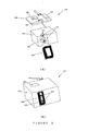
図1は産業プロセス材料7中および/またはその上に組み込まれる発光マーカ1のフィールドまたは現場追跡のためのシステム100を示している。発光マーカ1が波長F1の光で照射されるとき、これは特有の波長f11を含んでいるスペクトル2で発光する。産業プロセス材料7中またはその上に組み込まれる発光マーカ1の存在を検出するため、材料7はF1で照射され、材料7により放射される任意の光は集められ、これが波長f11の光を含んでいるか否かを調べるために検査される。このような動作を行うため、ポータブルな発光読取装置3が使用されることができる。読取装置3では、光源4は取付けられたコンピュータ12により要求されたとき波長F1の光を発生する。コンピュータ12は少なくとも1つのプロセッサ(図示せず)と、その少なくとも1つのプロセッサにより実行可能なプロセッサ命令とを含んでいる。随意選択的に、光源4はまたコンピュータ12により命令されるときに他の波長F2、F3、F4…Fmの光を発生することができる。光源4により発生された光は随意選択的に光ファイバまたは光ファイバエレメントの束5により集められ転送される。その代わりに読取装置3は光ファイバコレクタ5が視線の構成により置換されるように構成されることができ、視線の構成では光は光源4によって材料7へ直接転送される。
[Detailed description of the drawings]
FIG. 1 shows a
光ファイバまたは光ファイバの束6のヘッドには(または視線の構成が使用される場合には読取開口には)波長F1の光が存在し、極微量の発光材料1を含んでいる材料7上に入射する。極微量(または法定)量の発光材料1だけが材料7に存在できるので、これは非常に弱く、周囲光の数分の1程度の弱い発光ができる。周囲光は検出プロセスで妨害となるので、読取装置3が使用されるときには除外される。これは読取装置3のエラストマーキャップ6a(またはシュラウド)にヘッド6(または読取開口)を適合することにより実現され、エラストマーキャップ6aは読取装置のヘッドが材料7の任意の固体または粒子表面に対して加圧されるとき、それ自体が表面の形状にかたどられ、丁度読取装置のヘッド6と材料7との間の領域に全ての周囲光が入らないように実質上ブロックするように構成されている。材料7により放射される任意の結果的な発光はヘッド6に存在する第2の光ファイバまたは光ファイバエレメントの束8により集められる。これらは集められた光を分光計9へ転送し、分光計9は波長f11の存在を検出できる適切な感光素子10を含んでいる。
On the
分光計9は材料7により放射される光の特定の周波数を検出することのできる任意の通常の計測機であってもよい。このような機器は例えば少なくとも(a)入射光の存在を電気的に登録できる感光素子10と、(b)入射光の周波数を限定、特定または制御することのできる周波数制御素子を含むことができる。感光素子10の例には例えば(a)蛍光分光計または類似の装置、(b)適切なCCDチップまたは類似の装置、(c)フォトダイオードまたは類似の装置、(d)光電子増倍管または類似の装置、(e)選択された周波数の光で照射されるとき電気応答を生成することのできる半導体または類似の材料、(f)任意の方法で選択された周波数の光の存在を通報することのできる光活性の化学物質が含まれる。周波数制御素子の例には例えば(a)それぞれが別々に測定されることのできるように入射光を散乱しその構成周波数に分離するプリズムおよびスリットと、(b)光のある周波数だけの通過を選択的に可能にし、それによってこれらの周波数のみの選択的な検査を可能にする帯域通過、カットオフまたはその他のフィルタが含まれている。
The
感光素子10は測定されたデータをケーブル11aに沿ってインターフェースされたコンピュータ12へ伝送し、そのコンピュータ12はスペクトルまたは検出された周波数を計算し、波長f11を有する光が存在するか存在しないかに基づいて発光マーカ1が存在するか否かを決定する。コンピュータ12は放射波長f11により感光素子11で信号が存在するかしないかをチェックする度に(ケーブル11bを使用して)光源4を反復的にオンおよびオフに切り換えることができる。コンピュータ12はそれ故、それを反復し、データを積分することによって測定された観察を数学的に確認することができる。コンピュータ12はデータを感光素子10から集収する異なるときに光源4をオンおよびオフに切り換えることもでき、それによってスプリアスまたは背景データを除去し、或いは使用される発光マーカに特有の特徴的な応答または応答のパターンを発生する。
The
図1に示されているように、読取装置3は例えば、(i)ラップトップコンピュータまたはパーソナルデジタルアシスタント(PDA)12および適切な有線または無線の接続11と、(ii)オーシャンオプティックス(米国フロリダ州ダニーディン)により供給されるUSB2000小型化分光光度計9と、(iii)レーザーサイエンス社により供給され、光ファイバコネクタ5と適合されるVSL−337小型化紫外線レーザ4を使用して構成されることができる。
As shown in FIG. 1, the
代わりに光源4は例えば(i)250−365nmで動作し、日本のNichia社により供給される発光ダイオード(LED)と、(ii)オーシャンオプティックスにより供給されるPX2パルス励起キセノン光源と、(iii)365−1100nmの範囲で種々の可視および赤外線照射を発生することのできる市場で入手可能なLEDのうちの1以上を含むことができる。種々の他の固体または白熱光源4が使用されることができる。光源は除光エラストマーキャップ内に随意選択的に組み込まれることができる。良好に制御された光パルスを発生するために、Systron-Donner社により供給されるデータパルス100Aのようなパルス発生器およびLEDまたはその他の付勢回路がラップトップコンピュータ12と光源4との間に随意選択的に配置されることができる。
Instead, the
光ファイバケーブル6は例えば励起し、放射される光を伝送するためにオーシャンオプティックスにより供給される400ミクロンの厚さの二又光ファイバケーブルであるQBIF400−UV−VISとして構成されることができる。光ファイルケーブルは光ファイバの2つの層、即ち周囲に外部束8が設けられている内部束5を含んでいる。外部束の終点はレーザに固定された光ファイルへプラグ接続される。内部束5の終点は分光光度計9に固定された光ファイバにプラグ接続される。光ファイバケーブル6のヘッドには、2つの光ファイバ束がいわゆる「反射プローブ」で結合されている。反射プローブは典型的に2つの光ファイバ束を包み光ファイバの端部を超えて小さいリップ部を提供する金属アセンブリからなる。このリップ部は角度を付けて測定を行いたいときに角度(例えば30度)を付けられることができる。動作において、反射プローブは解析されるサンプルに対して強固に保持され、リップ部の目的は光ファイバヘッド6とサンプル7との間の空間中の外部周囲光を可能な限り多く除去することである。反射プローブ上のリップ部は金属であるために、これらは通常、サンプル表面と完全に相補的な適合を行うことができない。このように、それらは読取装置のヘッド6とサンプル7との間の空間に存在する全ての周囲光を遮断することができない。この難点を克服するため、このようなプローブの製造業者は反射プローブが適切に滑動できる適切な受け穴を含んでいる大きい陽極酸化されたアルミニウムブロックも供給し、これらのアルミニウムブロックは「反射プローブ保持装置」と呼ばれる。これらの寸法(典型的に7cm×4cmのフットプリント)のために、これらの保持装置はさらに周囲光を遮断するが、全てではない。
The
周囲光の存在を実質的に除去し、1以上の発光材料からなる極微量(法律量)の発光マーカの使用を可能にするために、重ゴムから作られる除光キャップ6aが読取装置のヘッダ6(または光ファイバコネクタが使用されない場合には読取装置の開口)へ取付けられる。キャップ6aは反射プローブ6(または読取装置の開口)が加圧される黒色の円錐型のゴムスリーブ部からなる。キャップ6aのスリーブ部は反射プローブ6に堅く適合する。キャップ6aの円錐状のゴムスリーブ部の下部近くには、第2の広いゴムの円錐が取付けられている。この円錐は一連の同心の円形ゴムリップ部を含んでおり、それぞれ読取ヘッドがサンプル表面に対して加圧されるときに周囲光を遮断することができる。ゴムキャップ6aは測定プロセス期間中に周囲光を除去する。
In order to substantially eliminate the presence of ambient light and to allow the use of a trace amount (legal amount) of light emitting marker made of one or more light emitting materials, a light removal cap 6a made of heavy rubber is used in the header of the reader 6 (or the opening of the reader if no fiber optic connector is used). The cap 6a is formed of a black conical rubber sleeve portion to which the reflection probe 6 (or the opening of the reading device) is pressed. The sleeve portion of the cap 6a fits tightly on the
読取装置3の動作はオーシャンオプティックス社により供給されるOOIBase32(商標名)またはOOIChem分光計オペレーティングソフトウェアを使用して制御されることができる。代わりに、注文されたソフトウェアが読取装置3の動作の制御に使用されることができる。ソフトウェアはレーザ4をオンおよびオフに切り換え、分光計9から受信されたデータを集収し処理する。制御PDAコンピュータおよびその電池を含む読取装置3全体は靴箱程度の寸法の体積に適合され、読取装置3を十分に携帯可能にする。読取装置のヘッド6上のゴムキャップ6aは読取装置がフィールド動作で常用されることを可能にし、産業プロセス材料中に存在する法定量の発光材料をその位置で確実および迅速に決定することを可能にする。ゴムキャップ6aはこのような追跡可能性を容易にする。例えば前述したVSLレーザ4はパルス当り約10マイクロジュールのパワーの光を発生する。この光源4と読取装置3とゴムキャップ6aを使用して、日常のフィールド測定において、市場で入手可能なコンクリート中に百万分の1−10の濃度で存在するある発光マーカを検出することが可能である。これは実質的に全ての周囲光を全て除光せずには実現されることができない。
The operation of the
読取装置3は材料7中の発光マーカの存在を検出するために検出アルゴリズム(またはプロトコル)を使用することができる。多数の可能な検出アルゴリズムは公式化されることができる。1つの典型的な検出アルゴリズムでは、システム100で使用される複数の発光マーカ1の特徴的な放射スペクトルはコンピュータ12に記憶されたデータベースに記憶されている。データベースを参照することにより、産業プロセス材料7中に存在する特定の発光マーカ1を識別することが可能である。したがって、例えば周波数F1の光で照射されるとき、発光マーカ1は2で示されるスペクトルを有する光を放射する。このスペクトルはスペクトル2aとしてコンピュータ12のデータベース中にデジタル形態で記憶されることができる。このデータベースはまた予め定められた発光マーカ7を含む種々の他の発光材料の放射スペクトルも含んでいる。産業プロセス材料7が周波数F1の光で照射されるとき、それはスペクトルを発生する。このスペクトルはアルゴリズムによりデータベースの各スペクトルと比較される。観察されるスペクトルが(予想される可変性の範囲内)2aに適合するならば、その産業プロセス材料7は明白に発光マーカ1を含まなければならない。この手段により、産業プロセス材料7内で極微量の特定の予め定められた発光マーカ1の存在を検出することができる。このプロセスは発光マーカ1と産業プロセス材料7の種々の他の組合せで反復されることができる。
The
代わりに、放射スペクトル2は周波数f11で特徴的で特有のピークを含むことができ、それは周波数F1の光で照明されるときシステム100中の他のどの発光マーカ1によっても放射されない。この検出アルゴリズムは周波数F1の光による照射から生じた放射スペクトルのこのピークの存在に対して発光マーカ1を関連付けることにより動作することができる。したがって、検出アルゴリズムは産業プロセス材料7が周波数F1の光で照明されるとき特定の強度のピークが周波数f11で観察されるか否かを通常のスペクトルマッチング技術を使用して検査することができる。このようなピークの存在は発光マーカ1の存在を確実にする。そのプロセスは特有の放射ピークを有する1以上の発光材料を含む他の発光マーカ1で反復されることができる。
Alternatively, the
波長F1の光で照明されるときそれぞれ特徴的および相互に異なる放射波長f11、f12、f13、f14...f1nで発光する多数の構成発光材料1、2、3、4...nの発光マーカ1が同時に存在することが同様に決定されることができる。読取装置3はそれぞれ1以上の多数の発光材料1−nを特徴な波長fm1、fm2、fm3、fm4...fmnで発光させる他の波長F2、F3、F4...Fmへ照明波長が逐次的に変更されるルーチンを実行するように構成されることができる。このようなケースで産業プロセス材料7の発光マーカ1内に組み込まれる各発光材料1−nは、単一波長Fmの光で照明されるとき少なくとも1つの顕著で特有の波長で発光することができるが、他の波長Fmの光で照射されるときには発光しない。多数の照射波長下において多数の波長で発光する発光材料を含んでいる発光マーカ1はそれらの放射が相互に干渉しないならば使用されることができる。
Light emission of a number of constituent light-emitting
図2は発光マーカ1として個別または異なる組合せで選択的に使用されることのできる発光材料1−13の例示的なセットの放射特性を示している。発光材料1−4はF1で照射されるとき特徴的に異なる波長で強力に発光するが、F2−F5で照射されるときには顕著に発光しない。同様に、発光材料6−7はF2で照射されるとき特徴的に発光するが、他のどの照射波長下でも発光しない。発光材料8−9はF3で照射されるときのみ効率的に発光し、それらの特徴的な放射波長は非常に異なる。材料11−12はF4で照射されるときのみ特徴的に放射し、材料13はF5で照射されるときのみ強力に発光する。発光材料5と10は2つの異なるFm波長で照射されるとき強力に発光する。しかしながらそれらの放射波長はこれらの波長で照射されるときに発光する他の発光材料に関して区別できる。それ故、これらの存在は材料1−13の異なる混合物を検出するときに曖昧さを導入しない。
FIG. 2 shows the radiation characteristics of an exemplary set of luminescent materials 1-13 that can be selectively used individually or in different combinations as the
発光材料1−13の混合物からなる発光マーカ1を含むことのできる産業プロセス材料7のサンプルを波長F1−F5で逐次的に照射し、各予測される波長fmnが存在するか存在しないかを決定することにより、存在する発光材料1−13を決定することができる。各発光材料の存在または不存在は二進コード(0=不存在、1=存在)を与えるので、これらの発光材料の多くの組合せが可能である。このようにして、産業プロセス材料は全ての他の可能なアドレスからそれらを弁別する特有の「アドレス」(またはコード)を割当てられることができ、それによって発光材料1−13を含む発光マーカ1でマークされる複数の、そうでなければ同一のアイテムの弁別を可能にする。
A sample of
図3は発光マーカ1を形成する前述の13の異なる発光材料の存在または不存在から得られる二進コード(またはアドレス)の典型的なマトリックスを示している。全ての発光材料の不存在は明白な情報を与えないので、発光材料の1つは常に存在しなければならず、この材料は理想的には稀な材料であり、自由に入手可能ではなく、その特性は任意の他の発光材料により模倣されない。図3に示されている例では、構成発光材料1は常に存在するように選択されている。この材料は広くおよび通常入手可能ではないので、この技術の使用の基準マーカとして作用する。13の全ての極微量の発光材料を含んでいる産業プロセス材料の場合、二進コード1111111111111が生成され、これはその産業プロセス材料の特有のアドレスになる。発光材料2を除く全てが別の産業プロセス材料に存在するならば、そのアドレスは1011111111111である。発光材料3を除く全てがさらに別の産業プロセス材料に存在するならば、これには二進コードアドレス1101111111111が与えられる。この方法は多くの異なる可能な二進コードを与え、したがって発光材料1−13の異なる組合せからなり、それぞれがその固有のアドレスを有する発光マーカ1でそれぞれマークされている多数の異なる産業プロセス材料の弁別を可能にする。
FIG. 3 shows a typical matrix of binary codes (or addresses) resulting from the presence or absence of the 13 different luminescent materials described above that form the
図1に示されている読取装置3は特定のプロセス、品質または論理制御タスクを行うために適切なアルゴリズムにしたがって、選択的に発光マーカ1からなる1以上の発光材料の放射された発光の強度を検出し比較するようにプログラムされることもできる。このようなアルゴリズムは光源が付勢されるとき(またはパルスで付勢されるならばその直後に)紫外線、可視および赤外線領域の一連の「予測される」波長で受信される信号のデジタル振幅の測定を含んでいる。「予測される」波長は任意の意図的に組み込まれた発光材料が強く発光する波長である。例えば図2の場合、予測される波長はF1で照射されるときf11、f12、f13、f14であり、F2で照射されるときf25、f26、f27であり、F3で照射されるときf38、f39、f310であり、F4で照射されるときf45、f411、f412であり、F5で照射されるときf510、f513である。波長Fmの光によるサンプルの各照射では、予想される波長はそれらのそれぞれの測定された振幅データと共に逐次的に読取装置3のメモリチップに記憶される。予測される波長の受信された振幅が経験的に決定されたしきい値レベルを横切るならば、「1」はその波長についてのメモリのビンに登録され、横切らないならば、「0」が登録される。「1」と「0」の結果的なシーケンスは図3に示されているタイプの二進コードにコンパイルされる。このコンパイルのプロセスは2以上の異なる波長Fmで照射されるとき2以上の異なる波長fmnで発光する発光材料を考慮しなければならない、例えば図2では発光材料5は波長F2で照射されるとき波長f25で発光し、さらに波長F4で照射されるとき波長f45で発光する。発光材料5で全体的に「1」が登録されるように、「1」はF2で照射されるときf25、F4で照射されるときf45においてそれぞれ登録されなければならない。このようにして図3で示されているタイプの特有の二進コードが得られる。
The
発光材料の簡単な存在または不存在(「0」と「1」)の比較の代わりに、それらの特徴的な放射ピークの相対的な強度が比較され、その後さらに高次のコード化が可能である。例えば発光マーカ1の不存在が0により示され、マーカの完全な存在(最大強度)が2により示され、半分の強度の存在が1により示されるならば、0と1と2(即ち三進コード)を含むコードを作成することが可能である。このようなコードはさらに順列と組み合わせと二進コードを含み、それ故それに対応してより複雑になる。
Instead of simply comparing the presence or absence of luminescent materials (“0” and “1”), the relative intensities of their characteristic emission peaks are compared, which can then be further encoded. is there. For example, if the absence of the
通常、q個の非干渉発光マーカを含んでいるシステムにおいて、pにより解かれることのできる各特徴的な放射ピークの強度レベルの最大数がpであるならば、(p+1)-レベルコードが生成されることができる。このようなコードは(p+1)qの可能な順列および組み合わせを有する。 Typically, in a system containing q incoherent luminescent markers, if the maximum number of intensity levels of each characteristic emission peak that can be solved by p is p, then a (p + 1) -level code is generated Can be done. Such a code has (p + 1) q possible permutations and combinations.
前述の検出アルゴリズムおよび発光符合化技術は発光マーカ1を含んだ産業プロセス材料7を明白に識別する発光コードを生成するための単なる1方法を表しているに過ぎない。
The aforementioned detection algorithm and luminescence encoding technique represent just one way to generate a luminescent code that clearly identifies the
図4を参照すると、産業プロセス材料28は皮のなめしまたは鉱物の採掘のような産業で使用される水ベースの液体形態で入手された特別品または汎用化学製品を含んでいる。水溶性の発光材料20は極微量で化学物質28中に溶解される。結果的な溶液29はその後(例えば皮を加工しなめすため、または鉱石の本体から鉱物を抽出するための)産業プロセスで使用される。産業プロセスの生産物(例えば皮または部分的に加工された鉱物)はその後極微量または少量の発光マーカ20を含んでおり、したがって波長F1の光で照射されるとき特徴的な波長f12で発光する。この発光の強度は使用される化学物質28の投与量およびその使用の均一性に関する情報を提供できる。さらに化学物質28の移動および最終的な成り行きは発光マーカ20の廃棄物ダム29への分配をたどることとその廃棄物ダム29について監視されることができる。化学物質28が廃棄物ダム29から漏れたならば、その環境への漏洩30は、読取装置3を使用して発光マーカ20をサーチすることにより追跡され、範囲を定められ、波長F1の照射下で波長f12の特徴的な微量放射に対して感度があるように調節されることができる。例えば化学物質28が地下水中に入ったならば、その地下の移動は百万分の1程度に低い濃度で表面プール31における発光マーカ20のサインを探すことにより決定されることができる。このような漏洩の起点および原因はしたがって容易に検出され、法的および環境的なコンプライアンスな測定が行われる。発光マーカ20が関係するなめしまたは採掘にのみ利用可能であるならば、皮または部分的に加工された鉱物の原石はさらに回復不能であるように産物上にマークされる。さらに詳細な情報は前述したように、それぞれ多数の異なる発光材料のコード化された組合せからなる発光マーカ20の使用によって汎用または特別の化学製品28内に埋設されることができる。
Referring to FIG. 4, the
図5の(A)および(B)はフィールド中の位置または現場で産業プロセス材料の極微量の発光マーカを非侵入的に光学的に検出するように特別に構成されている一体化されたポータブル発光読取装置200を示している。この読取装置200はポータブル分光計210、例えばポータブルなオーシャンオプティックS1分光計を含んでいる。分光計210は入力光学ポート230が設けられている正面の凹部220を有している。2つの発光ダイオード(LED)240は分光計210の入力光学ポート230の反対側の凹部220にも配置されている。LED240の一方または両者は約250nm乃至365nmの波長範囲を有する光放射を放射することができる。しかしながら、特定の応用にしたがって、両LED240はこの波長範囲外の光放射をすることができる。LEDの寸法とパワーおよび関与する応用にしたがって、読取装置200は3以上のLED240を含むことができる。
FIGS. 5A and 5B show an integrated portable that is specifically configured to non-intrusive optically detect trace amounts of luminescent markers of industrial process materials in-field or in the field. A light
約250nm乃至365nmの波長範囲を有する光放射をするように調節されているLED240の使用は適切な発光マーカの実質的な割合がこの周波数範囲内で強く吸収し、したがってこれらの状態下でもこれらが可能である程度またはほぼその程度の強さの放射を行う。したがって、約250nm乃至365nmの波長範囲で動作するLED240は広い多様性の発光マーカを励起するために使用されることができる。さらに、このようなLED240の使用は通常、他の周波数のLEDが使用される場合よりも少量の発光マーカを使用することを可能にする。
The use of
図5の(A)に示されているように、LED240は入力光ポート230に直接隣接するかそれを超える領域を照射するように、分光計210の入力光ポート230のいずれかの側面上の凹部220に配置される。この領域が照射されるとき、この領域の任意の発光マーカにより放射される光放射は部分的に分光計210の入力光ポート230へ直接誘導され、それによって捕捉される。必要がある場合、光ファイバ「スタブ」または小さいレンズ(図示せず)はこの光の捕捉を容易にしまたは強化するために入力光ポート230へ設けられることができる。ハウジング220の凹部はフレキシブルな不透明のシュラウド250、例えば読取装置200が関係する産業プロセス材料上に位置付けられるかそれに近接して配置されるとき、分光計210の入力光ポート230から周囲光を除光するゴムのシュラウドにより包囲される。しかしながら特別な応用では、周囲光を効率的に除光する他のタイプの構造が使用されることもできる。例えばスプリングが装着されたカバーにより適合されたスロット、即ち関係する材料を適合するような特別注文された構造も使用されることができる。
As shown in FIG. 5A, the
分光計210とLED240は、読取装置200のコンポーネントへ電力を与える適切な小型の電池270と共に分光計210の表面に取付けられる特別注文の回路板260に接続され制御される。この回路板260はLED駆動回路を含み、それはLED240が回路板260上に含まれているマイクロプロセッサ280によりオンおよびオフに切り換えられることを可能にする。回路板260はまた読取装置200を開始/停止し、他の機能を行うためのディスプレイ290およびスイッチ300も含んでいる。マイクロプロセッサ280は例えば検出アルゴリズムにより、取付けられたデータポートを介してデータでプログラムされることができる。読取装置200により使用される検出アルゴリズムはマイクロプロセッサ280へダウンロードされ、付勢されるときに読取装置200の動作を制御する。読取装置200はその最も外部の可視本体を具備する特別注文のハウジング310中に収納されている。ハウジング310は審美的に許容可能なパッケージ内にディスプレイ290、ゴムの遮光シュラウド250、スイッチ300を収容している。このように構成された読取装置200は小型で十分に携帯可能であり、ほぼ大きいポケット計算機の大きさである。高度に多能性の発光マーカを検出するための種々の動作行為および検出アルゴリズムを適用することができるので非常に汎用性がある。読取装置200は遠隔コンピュータとの無線および/または有線データ通信のための無線および/または有線ネットワーク、例えば中央サーバに接続されて動作することができる。
本発明を以下の実施例で説明する。例は任意の方法による本発明の限定として解釈されない。 The invention is illustrated in the following examples. The examples are not to be construed as limiting the invention in any way.
[実施例]
以下の実施例1−3では、発光マーカ1はピレンであり、これは波長337nm(これらの例の目的ではF1)の光を吸収し、特徴的な波長367nm(これらの例の目的ではf11)で発光する。発光マーカ2はAgで活性された硫化亜鉛であり、これは波長337nm(F1)の光を吸収し、451nm(これらの例の目的ではf12)で特徴的に光を放射する。発光マーカ3はMnで活性化されたマグネシウムフルオロゲミネートであり、これは波長337nm(これらの説明の目的ではF1)の光で照射されたとき、425nm(これらの例の目的ではf14)で特徴的に放射する。
[Example]
In Examples 1-3 below, the
例1:コンクリートおよびセメント製品の品質および論理制御
発光マーカ1(15グラム)が1500グラムのポリマー、ポリメチルメタクリル酸メチル(PMMA)を含んでいるジクロロメタン溶液で溶解される。この溶液は商用の噴霧乾燥器を使用して噴霧乾燥され、1%wt/wt比を含んでいる微細なポリマービーズでカプセル化された発光マーカ1を与える。極微量の発光マーカ1(150グラムのPMMAポリマー内で1.5グラム)は2リットルの水で懸濁され、ミキサトラック13内のコンクリートの単一のバッチ(7立方メートル)に付加される。ミキサはレデーミクスコンクリート産業で標準的であるように最大の回転で4分間動作される。ミキサはその後低速度の回転に設定され、トラックはコンクリートバッチが再度最大の回転で2分間混合される注入場所へ進む。注入と硬化の後、コンクリートバッチの正確な位置とコンクリートの他の注入されたバッチ内の境界は読取装置によりコンクリートの表面を検査することにより決定されることができる。読取装置は図1に示されているような構成であり、F1を生成するように同調され、f11を検出するために調節される。読取装置はラップトップコンピュータと、オーシャンオプティックス社により供給されるUSB2000小型化分光光度計と、レーザーサイエンス社により供給され、光ファイバコネクタと適合されるVSL−337小型化UVレーザと、Systron-Donner社により供給されるデータパルス100Aパルス発生器と、(励起および放射光を伝播するための)QBIF−400−UV−V15として構成されオーシャンオプティックスにより供給される400nmミクロンの厚さの二又光ファイバケーブルからなる。光ファイルケーブルは光ファイバの2つの層、即ち周囲に外部束が構成されている内部束を含んでいる。外部束の終点はレーザに固定された光ファイルへプラグ接続される。内部束の終点は分光光度計に適合された光ファイバにプラグ接続される。プローブのヘッドには、円錐状のゴムのスリーブからなるキャップが適合されている。キャップの円錐状のゴムスリーブ部の下部近くには、第2の広いゴムの円錐が取付けられている。この円錐は一連の同心の円形ゴムリップ部を含んでおり、それぞれ読取ヘッドがサンプル表面に対して加圧されるときに周囲光を遮断することができる。読取装置の動作はオーシャンオプティックス社により供給されるOOIBase37(商標名)オペレーティングソフトウェアを使用して制御される。検出はコンクリートの表面にわたって読取装置のヘッドを滑動することにより実現される。F1による照射時にコンクリートの放射スペクトルのF11が存在することは、バッチの物理的位置を示している。発光材料1を含まない他のバッチはF1による照射時に明白な信号f11を発生しない。
Example 1: Quality and logic control of concrete and cement products
Luminescent marker 1 (15 grams) is dissolved in a dichloromethane solution containing 1500 grams of polymer, polymethyl methyl methacrylate (PMMA). This solution is spray dried using a commercial spray dryer to give a
カプセル化されていない発光材料2および3はF1による照射時にそれぞれf12とf13の検出により同様にコンクリートをマークするために使用されることができる。
Unencapsulated
例2:木材および木材製品のプロセス、品質、論理制御
木材製品は発光マーカ4によりマークされる。発光マーカ4はホワイトスピリットおよび強力で溶解可能な殺虫剤からなる商用の木材防腐液中で0.003%のwt/wt比で溶解される。結果的な混合物は防腐剤および極微量の発光マーカ4を含んでいる。
Example 2: Process, quality and logical control of wood and wood products
The wood product is marked by a
防腐剤で木材を処理するための高圧力シリンダは木材片(1m×7cm×7cm)を投入される。シリンダは試験目的だけに使用される非商業的な試験工場である。シリンダは密封され、部分的な真空(85KPa)下に15分間保持される。シリンダはその後入口弁を通って発光マーカを含んでいる木材防腐液に充填される。防腐剤は発光マーカを有する木材に浸透する。正圧力(700KPa)がその後、可能な限り多くの防腐液を木材へ浸透させるために5分間シリンダに加えられる。この圧力を解除した後、シリンダは開封され、木材が取り出される。 A high pressure cylinder for treating wood with preservatives is loaded with wood pieces (1 m × 7 cm × 7 cm). Cylinders are non-commercial test factories that are used for test purposes only. The cylinder is sealed and held for 15 minutes under partial vacuum (85 KPa). The cylinder is then filled with wood preservative containing the luminescent marker through an inlet valve. Preservatives penetrate into wood with luminescent markers. Positive pressure (700 KPa) is then applied to the cylinder for 5 minutes to allow as much preservative as possible to penetrate the wood. After releasing this pressure, the cylinder is opened and the wood is removed.
読取装置を使用する木材表面の検査は例1に説明されているように、波長F1の光で照射するとき波長f14で均等に発光することを示す。したがって、木材の外部は均等に防腐液により処理される。木材片が2つの片に切断されるとき、新しく切断された表面の読取装置によって検査では、波長F1の光で照射するとき内部表面も波長f14で発光することが明らかにされている。したがって、この解析は木材の外部および内部の両者が発光マーカ4により均等にマークされたことを明らかにしている。
Inspection of the wood surface using a reader shows that, as described in Example 1, it emits evenly at wavelength f14 when illuminated with light of wavelength F1. Therefore, the outside of the wood is treated with the preservative liquid evenly. When a piece of wood is cut into two pieces, inspection by a newly cut surface reader reveals that the inner surface also emits at wavelength f14 when illuminated with light of wavelength F1. Thus, this analysis reveals that both the exterior and interior of the wood were evenly marked by the
例3:所有物管理のための吹付け塗装
エアロゾルが推進剤、クリア、自然乾燥ラッカーまたはエナメル、および発光ラッカー1または4により重量で0.5%(即ち内容物の100グラム当り0.5g)で充填される。エアロゾルのパッケージに使用されるマシンは専売のColorPak 300gエアロゾル塗料充填システムであり、これは溶剤と推進剤の予めパックされた混合物と共に、空気圧で動作されるエアロゾル充填マシンからなる。所有物はエアロゾルにより吹付けられ、ラッカー/塗料は乾燥を可能にされる。波長f11とf14の識別は所有物の表面を覆って(例1で説明したように波長F1を放射する)読取装置を使用することにより検出される。
Example 3: Spray painting for property management
The aerosol is filled with propellant, clear, air-dried lacquer or enamel, and
この明細書および請求項を通して、文脈が特に必要としなければ、用語“comprise”と“comprises”、“comprising”のような変形は前述した完全体またはステップまたは完全体のグループを含むことを示唆しているが、任意の他の完全体またはステップまたは完全体のグループを除外することを示唆していないことが理解されるであろう。 Throughout this specification and claims, unless the context requires otherwise, it is implied that variations such as the terms “comprise” and “comprises”, “comprising” include the complete forms or steps or groups of complete forms described above. It will be understood, however, that it does not suggest excluding any other whole body or step or group of whole bodies.
任意の従来の出版物(またはそれから得られる情報)または知られている任意の事項に対するこの明細書の参照は、この明細書が関連する技術分野におけるそれらの従来の出版物(またはそれから得られる情報)または知られている任意の事項が共通の一般的知識の一部を形成することを承認または許可或いは示唆するものではなく、そのように解釈されるべきではない。 References in this specification to any conventional publication (or information obtained therefrom) or to any known matter are those prior publications (or information obtained therefrom) in the technical field to which this specification relates. ) Or any known matter does not approve, permit or suggest that it forms part of the common general knowledge and should not be so construed.
Claims (30)
内部および/または表面上に極微量の発光マーカを選択的に組み込むことによって産業プロセス材料上に特有の発光応答特性を与え、
その特有の発光応答特性に対応するフィールド中の位置または現場で産業プロセス材料からの発光応答を検出することにより、その複数のライフサイクル段期間中に産業プロセス材料を識別または確認するステップを含んでいる方法。 In a method for tracking industrial process materials through multiple lifecycle stages,
Provide specific luminescent response characteristics on industrial process materials by selectively incorporating trace luminescent markers internally and / or on the surface;
Identifying or confirming the industrial process material during its multiple life cycle stages by detecting the luminescent response from the industrial process material at a location in the field or in the field corresponding to its unique luminescent response characteristics. How.
産業プロセス材料、製品、部品および/または構造物に関する情報と、それらの対応する与えられた特有の発光応答特性とを関連して記憶するデータベースと、
ポータブル発光読取装置により検出された発光応答と、データベース中に記憶されている与えられた特有の発光応答とをプロセッサに比較させ、産業プロセス材料、製品、部品および/または構造物を識別するプロセッサ命令を含んでいるシステム。 A portable light-emitting reader configured to detect in a field location or in-situ a unique light-emitting response characteristic imparted to industrial process materials and / or products, parts or structures formed therefrom;
A database that stores information relating to industrial process materials, products, parts and / or structures in association with their corresponding given unique luminescent response characteristics;
Processor instructions for identifying industrial process materials, products, parts and / or structures by causing the processor to compare the luminescent response detected by the portable luminescent reader with a given specific luminescent response stored in the database Including system.
Applications Claiming Priority (2)
| Application Number | Priority Date | Filing Date | Title |
|---|---|---|---|
| AU2005902346A AU2005902346A0 (en) | 2005-05-10 | System for tracking and identification of materials | |
| PCT/AU2006/000608 WO2006119561A1 (en) | 2005-05-10 | 2006-05-10 | High-resolution tracking of industrial process materials using trace incorporation of luminescent markers |
Related Child Applications (1)
| Application Number | Title | Priority Date | Filing Date |
|---|---|---|---|
| JP2012003780A Division JP2012123004A (en) | 2005-05-10 | 2012-01-12 | High-resolution tracking of industrial process materials using trace of luminescent markers |
Publications (2)
| Publication Number | Publication Date |
|---|---|
| JP2008541064A true JP2008541064A (en) | 2008-11-20 |
| JP2008541064A5 JP2008541064A5 (en) | 2009-07-02 |
Family
ID=37396095
Family Applications (4)
| Application Number | Title | Priority Date | Filing Date |
|---|---|---|---|
| JP2008510360A Withdrawn JP2008541064A (en) | 2005-05-10 | 2006-05-10 | High-resolution tracking of industrial process materials using luminescent marker traces |
| JP2012003780A Withdrawn JP2012123004A (en) | 2005-05-10 | 2012-01-12 | High-resolution tracking of industrial process materials using trace of luminescent markers |
| JP2014096350A Withdrawn JP2014206537A (en) | 2005-05-10 | 2014-05-07 | High-resolution tracking of industrial process materials using trace incorporation of luminescent markers |
| JP2016105455A Pending JP2016188865A (en) | 2005-05-10 | 2016-05-26 | High-resolution tracking of industrial process material using trace of luminescent marker |
Family Applications After (3)
| Application Number | Title | Priority Date | Filing Date |
|---|---|---|---|
| JP2012003780A Withdrawn JP2012123004A (en) | 2005-05-10 | 2012-01-12 | High-resolution tracking of industrial process materials using trace of luminescent markers |
| JP2014096350A Withdrawn JP2014206537A (en) | 2005-05-10 | 2014-05-07 | High-resolution tracking of industrial process materials using trace incorporation of luminescent markers |
| JP2016105455A Pending JP2016188865A (en) | 2005-05-10 | 2016-05-26 | High-resolution tracking of industrial process material using trace of luminescent marker |
Country Status (11)
| Country | Link |
|---|---|
| US (2) | US9361561B2 (en) |
| EP (1) | EP1880236B1 (en) |
| JP (4) | JP2008541064A (en) |
| CN (3) | CN102818793A (en) |
| AU (1) | AU2006246300B2 (en) |
| BR (1) | BRPI0609385A2 (en) |
| CA (1) | CA2607513C (en) |
| NZ (1) | NZ563127A (en) |
| RU (1) | RU2007145437A (en) |
| WO (1) | WO2006119561A1 (en) |
| ZA (1) | ZA200709693B (en) |
Cited By (3)
| Publication number | Priority date | Publication date | Assignee | Title |
|---|---|---|---|---|
| JP2011227066A (en) * | 2010-03-30 | 2011-11-10 | Hakodate Regional Industry Promotion Organization | Labeled additive for food product, medicine or feed, manufacturing method for same labeled additive, and identification method of food product, medicine or feed |
| JP2019523838A (en) * | 2016-06-13 | 2019-08-29 | インヴィスタ テキスタイルズ(ユー.ケー.)リミテッド | Methods and compositions for transmitting yarn fiber properties, enhancing yarn color, and improving processing of bulk continuous filament fibers |
| WO2024048564A1 (en) * | 2022-08-30 | 2024-03-07 | 三井金属鉱業株式会社 | Active material, method for producing recycled active material, method for tracking valuable element recovered from battery, and compound for tracking |
Families Citing this family (55)
| Publication number | Priority date | Publication date | Assignee | Title |
|---|---|---|---|---|
| RU2008110930A (en) * | 2005-08-22 | 2009-09-27 | Коммонвелт Сайентифик энд Индастриал Рисерч Организейшн (AU) | METHOD FOR MONITORING AND CONTROL OF DISPLACEMENT PROCESSES |
| DE102006056103A1 (en) * | 2006-11-24 | 2008-05-29 | Siemens Ag | Monitoring material flow in production processes of building groups or construction units, comprises mixing an UV-active additive to a raw thermosetting polymer in a molding process and detecting light emission of the additive |
| WO2008138044A1 (en) * | 2007-05-11 | 2008-11-20 | Commonwealth Scientific And Industrial Research Organisation | Explosive tagging |
| WO2008144811A1 (en) | 2007-05-25 | 2008-12-04 | Orica Explosives Technology Pty Ltd | Use of post-blast markers in the mining of mineral deposits |
| GB0801479D0 (en) | 2008-01-26 | 2008-03-05 | Smartwater Res Ltd | Improvements to methods of in field analysis |
| US9133318B2 (en) * | 2008-09-02 | 2015-09-15 | Flint Trading, Inc. | Taggants for thermoplastic marking materials |
| US8866108B1 (en) | 2009-01-26 | 2014-10-21 | Krowker Direny | Microtagging motor vehicles for identification from a paint sample discovered during a criminal investigation |
| DE102009018688B4 (en) * | 2009-04-23 | 2017-03-02 | Knauf Insulation | Mineral wool product |
| DE102009022682A1 (en) * | 2009-05-26 | 2010-12-02 | Osram Opto Semiconductors Gmbh | Method for producing a light-emitting diode |
| JP2013514249A (en) * | 2009-12-18 | 2013-04-25 | コンストラクション リサーチ アンド テクノロジー ゲーエムベーハー | Qualitative and quantitative identification methods for bulk materials |
| DE102010007566A1 (en) | 2010-02-10 | 2011-08-11 | Tailorlux GmbH, 48565 | Luminescent safety element for product protection |
| GB2477741A (en) * | 2010-02-10 | 2011-08-17 | Smartwater Res Ltd | Fluorescent materials used in marker systems |
| DE102010028818A1 (en) | 2010-05-10 | 2011-11-10 | Swiss Authentication Research And Development Ag | Combination of luminescent substances |
| US20110305919A1 (en) * | 2010-06-10 | 2011-12-15 | Authentix, Inc. | Metallic materials with embedded luminescent particles |
| US20120021120A1 (en) * | 2010-07-23 | 2012-01-26 | Michael David Feldstein | Coatings with identification and authentication properties |
| GB201105619D0 (en) * | 2011-04-04 | 2011-05-18 | Smartwater Technology Ltd | |
| US9080987B2 (en) | 2011-05-26 | 2015-07-14 | Altria Client Services, Inc. | Oil soluble taggants |
| US9244017B2 (en) | 2011-05-26 | 2016-01-26 | Altria Client Services Llc | Oil detection process and apparatus |
| GB2491814A (en) * | 2011-06-06 | 2012-12-19 | Smartwater Ltd | A method of generating a composition for identifying goods |
| GB201110508D0 (en) * | 2011-06-22 | 2011-08-03 | Smartwater Technology Ltd | A method for applying a marker to an electrical cable during manufacture |
| WO2013018614A1 (en) * | 2011-07-29 | 2013-02-07 | 日本電気株式会社 | Comparison/search system, comparison/search server, image characteristic extraction device, comparison/search method, and program |
| RU2479673C1 (en) * | 2011-09-05 | 2013-04-20 | Александр Григорьевич Григорьянц | Impulse electrogasdynamic formation method of identification marks on surface of solid material |
| WO2013113061A1 (en) * | 2012-01-31 | 2013-08-08 | Bioconst Pty Ltd | A fluorescent composition for use in marking objects, such as flowers. |
| US10900897B2 (en) * | 2012-05-29 | 2021-01-26 | Altria Client Services Llc | Oil detection process |
| US9097668B2 (en) | 2013-03-15 | 2015-08-04 | Altria Client Services Inc. | Menthol detection on tobacco |
| WO2014184385A1 (en) | 2013-05-17 | 2014-11-20 | Kayhan Zirhlioglu | Identifiable and distinguishable cable sheathing |
| DE102013105117A1 (en) | 2013-05-17 | 2014-12-04 | Kayhan Zirhlioglu | Identifiable cable sheath |
| DE202013102180U1 (en) | 2013-05-17 | 2014-08-18 | Kayhan Zirhlioglu | Identifiable cable sheath |
| US20150332040A1 (en) * | 2014-05-19 | 2015-11-19 | Honeywell International Inc. | Systems, Devices, and Methods for Authenticating A Value Article |
| CN104200190B (en) * | 2014-09-03 | 2017-10-27 | 北京嘉华汇诚科技有限公司 | A kind of label creating and its reading method reviewed for logistics |
| WO2016077471A1 (en) | 2014-11-11 | 2016-05-19 | Altria Client Services Inc. | Method for detecting oil on tobacco products and packaging |
| CN104865252B (en) * | 2015-06-11 | 2018-08-24 | 中储粮成都粮食储藏科学研究所 | A kind of bulk grain label and the method for distinguishing that reflects |
| CN105092836B (en) * | 2015-07-20 | 2017-04-05 | 中国科学院上海光学精密机械研究所 | Up-conversion luminescence immuno-chromatography detection device and detection method |
| CN106598110B (en) * | 2015-10-19 | 2018-09-04 | 沈阳新松机器人自动化股份有限公司 | Novel spraying machine people's positive-pressure explosion-proof system |
| US20190344506A1 (en) * | 2015-12-08 | 2019-11-14 | U-Nica Technology Ag | Three-Dimensional Printing Method for Producing a Product Protected Against Forgery by Means of a Security Feature |
| EP3301451B1 (en) * | 2016-09-30 | 2019-12-18 | F. Hoffmann-La Roche AG | Qc system and method |
| CA3046787A1 (en) * | 2016-12-15 | 2018-06-21 | Gemological Institute Of America, Inc. (Gia) | Device and method for screening gemstones |
| DE102017108983B4 (en) * | 2017-04-26 | 2021-07-08 | Sensor-Instruments Entwicklungs- Und Vertriebs-Gmbh | Optical product inspection system |
| US9970949B1 (en) * | 2017-06-02 | 2018-05-15 | David R. Hall | Method for identifying and tracking pharmaceutical and nutritional products using nanoparticles of different sizes and shapes |
| US10781539B2 (en) * | 2017-08-25 | 2020-09-22 | Paul J. Serbiak | Authenticatable articles, fabric and method of manufacture |
| FR3071256B1 (en) * | 2017-09-15 | 2022-04-08 | Psa Automobiles Sa | PROCESS FOR PHOSPHATING PARTS WITH THE INCORPORATION OF AN OPTICAL PLOTTER |
| US11835459B2 (en) | 2018-05-03 | 2023-12-05 | Uster Technologies Ag | Textile brightness measurement system |
| US11262298B2 (en) * | 2018-08-30 | 2022-03-01 | Caterpillar Inc. | System and method for determining fluid origin |
| US11894109B1 (en) * | 2018-10-15 | 2024-02-06 | Nantcell, Inc. | Production and delivery tracking and sample verification of patient-specific therapeutics |
| KR102008934B1 (en) * | 2018-11-26 | 2019-08-08 | 한국조폐공사 | Plastic product comprising photoluminescent material and method for determining authenticity of the same |
| DE102019201529A1 (en) * | 2019-02-06 | 2020-08-06 | Hahn-Schickard-Gesellschaft für angewandte Forschung e.V. | Control device for a manufacturing plant, tracking device, manufacturing data determiner, methods and computer program |
| JP7283198B2 (en) | 2019-04-16 | 2023-05-30 | コニカミノルタ株式会社 | Resin deterioration evaluation test method, resin recycling system using the same, and resin deterioration evaluation device |
| DE102019127894B4 (en) | 2019-10-16 | 2022-05-12 | Sensor-Instruments Entwicklungs- Und Vertriebs-Gmbh | PRODUCT IDENTIFICATION SYSTEM AND PROCEDURES FOR IDENTIFICATION OF A PRODUCT |
| CN114467018A (en) | 2019-11-06 | 2022-05-10 | 乌斯特技术股份公司 | Apparatus and method for optically characterizing textile samples |
| RU2744458C1 (en) * | 2020-06-08 | 2021-03-09 | Федеральное государственное бюджетное образовательное учреждение высшего образования "Чувашский государственный университет имени И.Н. Ульянова" | Use of derivatives of phenylcyanocoumarin as a fluorescent marker in the marking and identification of rubber products |
| CN112525840B (en) * | 2020-11-25 | 2023-07-25 | 中海沥青股份有限公司 | Rapid identification method for petroleum asphalt source |
| GB202105485D0 (en) * | 2021-04-16 | 2021-06-02 | Saf T Glo Ltd | Indicator |
| CN114959679B (en) * | 2022-05-31 | 2024-02-02 | 浙江理工大学 | Cold spraying auxiliary device |
| US11867637B2 (en) * | 2022-12-15 | 2024-01-09 | EllansaLabs Inc. | Systems for authentication and related devices and methods |
| US11783145B2 (en) | 2022-12-21 | 2023-10-10 | EllansaLabs Inc. | Systems for authentication and related devices and methods |
Citations (5)
| Publication number | Priority date | Publication date | Assignee | Title |
|---|---|---|---|---|
| JP2002505426A (en) * | 1998-02-24 | 2002-02-19 | アイソタッグ、テクノロジー、インコーポレーテッド | How to mark items for identification |
| JP2003531734A (en) * | 2000-04-06 | 2003-10-28 | クアンタム・ドット・コーポレーション | Discriminable spectral barcode method and system |
| JP2004534953A (en) * | 2001-07-11 | 2004-11-18 | ゼネラル・エレクトリック・カンパニイ | Markers, methods and products for polymers |
| JP2005055735A (en) * | 2003-08-06 | 2005-03-03 | Id Technica:Kk | Identification information containing substance using dna base sequence as identification information, object to be identified, and authentication method |
| JP2005118420A (en) * | 2003-10-20 | 2005-05-12 | Olympus Corp | Identification device of restoration tooth |
Family Cites Families (92)
| Publication number | Priority date | Publication date | Assignee | Title |
|---|---|---|---|---|
| US4150295A (en) * | 1978-01-05 | 1979-04-17 | Analytical Radiation Corporation | Method and apparatus for background correction in photoluminescent analysis |
| CH659145A5 (en) * | 1980-05-30 | 1986-12-31 | Gao Ges Automation Org | METHOD FOR CHECKING THE VALIDITY OF SECURITIES SECURED WITH LUMINESCENT SUBSTANCES AND DEVICE FOR IMPLEMENTING THE METHOD. |
| US4387112A (en) * | 1980-10-23 | 1983-06-07 | Blach Rodney J | Article identification process and articles for practice thereof |
| US4485308A (en) * | 1982-04-26 | 1984-11-27 | General Electric Company | Photo detection system |
| US4703572A (en) * | 1982-09-27 | 1987-11-03 | Chapin William L | Animated ultraviolet display apparatus |
| US4565022A (en) * | 1982-09-27 | 1986-01-21 | Chapin William L | Method and apparatus for animating illuminated signs and displays |
| US4546416A (en) * | 1984-01-30 | 1985-10-08 | Pemberton J C | Phosphorescent flash-light |
| US4549081A (en) * | 1984-03-15 | 1985-10-22 | Ace Sophisticates, Inc. | Spectrophotometer for measuring absorption characteristics of a complex lens |
| JPS60209146A (en) * | 1984-03-31 | 1985-10-21 | Olympus Optical Co Ltd | Fluorescence spectrochemical analysis device |
| US5296380A (en) * | 1992-09-03 | 1994-03-22 | Israel Institute For Biological Research | Method and kit for detecting explosives |
| US5736410A (en) * | 1992-09-14 | 1998-04-07 | Sri International | Up-converting reporters for biological and other assays using laser excitation techniques |
| US5422719A (en) | 1993-11-12 | 1995-06-06 | Auburn International, Inc. | Multi-wave-length spectrofluorometer |
| IL110597A (en) * | 1994-08-09 | 2002-11-10 | Micro Tag Temed Ltd | Method for labeling, verification and/or identifying an object and device for implementing said method |
| US5498280A (en) * | 1994-11-14 | 1996-03-12 | Binney & Smith Inc. | Phosphorescent and fluorescent marking composition |
| US5569317A (en) * | 1994-12-22 | 1996-10-29 | Pitney Bowes Inc. | Fluorescent and phosphorescent tagged ink for indicia |
| US6232124B1 (en) * | 1996-05-06 | 2001-05-15 | Verification Technologies, Inc. | Automated fingerprint methods and chemistry for product authentication and monitoring |
| GB9614261D0 (en) | 1996-07-06 | 1996-09-04 | Secr Defence | A covert mark and security marking system |
| US5714758A (en) * | 1996-10-10 | 1998-02-03 | Surface Optics Corp. | Portable infrared surface inspection system |
| CA2281205A1 (en) * | 1997-02-12 | 1998-08-13 | Eugene Y. Chan | Methods and products for analyzing polymers |
| AU737221B2 (en) * | 1997-06-11 | 2001-08-16 | Nalco Chemical Company | Solid-state fluorometer and methods of use therefor |
| US5958780A (en) * | 1997-06-30 | 1999-09-28 | Boston Advanced Technologies, Inc. | Method for marking and identifying liquids |
| US20020158212A1 (en) * | 1998-04-17 | 2002-10-31 | French Todd E. | Apparatus and methods for time-resolved optical spectroscopy |
| DE19804012A1 (en) * | 1998-02-02 | 1999-08-05 | Giesecke & Devrient Gmbh | Value document |
| US6188996B1 (en) * | 1998-05-22 | 2001-02-13 | Pitney Bowes Inc. | System for metering permit mail |
| US6380547B1 (en) * | 1998-06-09 | 2002-04-30 | Manuel E. Gonzalez | Tagging compositions and methods |
| US7433035B2 (en) * | 1998-06-29 | 2008-10-07 | San Diego State University Research Foundation | Detection of carbon halogen bonds |
| US6617583B1 (en) * | 1998-09-18 | 2003-09-09 | Massachusetts Institute Of Technology | Inventory control |
| US6251303B1 (en) * | 1998-09-18 | 2001-06-26 | Massachusetts Institute Of Technology | Water-soluble fluorescent nanocrystals |
| EP1116036B1 (en) * | 1998-09-18 | 2004-08-11 | Massachusetts Institute Of Technology | Water-soluble fluorescent semiconductor nanocrystals |
| US6270213B1 (en) * | 1998-09-30 | 2001-08-07 | Pitney Bowes Inc. | Fluorescent and phosphorescent ink for use with an information based indicia |
| US6211526B1 (en) * | 1998-09-30 | 2001-04-03 | The United States Of America As Represented By The Secretary Of The Navy | Marking of materials using luminescent and optically stimulable glasses |
| US6142380A (en) * | 1998-09-30 | 2000-11-07 | Pitney Bowes Inc. | Usage of dual luminescent inks to produce a postal orienting and sorting identification mark for an information-based indicia |
| US6165609A (en) * | 1998-10-30 | 2000-12-26 | Avery Dennison Corporation | Security coatings for label materials |
| US6274381B1 (en) * | 1998-11-09 | 2001-08-14 | Rohm And Haas Company | Method for invisibly tagging petroleum products using visible dyes |
| US6274873B1 (en) * | 1998-11-18 | 2001-08-14 | Dna Technologies Inc. | Spectrum analyzer for reading authentication marks |
| US6536672B1 (en) * | 1998-11-18 | 2003-03-25 | Dna Technologies, Inc. | Product authentication system and method |
| US6354501B1 (en) * | 1998-11-18 | 2002-03-12 | Crossoff Incorporated | Composite authentication mark and system and method for reading the same |
| US6123871A (en) * | 1999-01-11 | 2000-09-26 | Carroll; Michael Lee | Photoluminescence polymers, their preparation and uses thereof |
| US6490030B1 (en) * | 1999-01-18 | 2002-12-03 | Verification Technologies, Inc. | Portable product authentication device |
| US7038766B2 (en) * | 1999-04-01 | 2006-05-02 | Microtrace, Llc | Identification particles and system and method for retrospective identification using spectral codes |
| AU4553000A (en) * | 1999-04-20 | 2000-11-02 | Honeywell Specialty Chemicals Seelze Gmbh | Inorganic illuminants made of finest grains |
| US6608716B1 (en) * | 1999-05-17 | 2003-08-19 | New Mexico State University Technology Transfer Corporation | Optical enhancement with nanoparticles and microcavities |
| US7079230B1 (en) * | 1999-07-16 | 2006-07-18 | Sun Chemical B.V. | Portable authentication device and method of authenticating products or product packaging |
| US6874639B2 (en) * | 1999-08-23 | 2005-04-05 | Spectra Systems Corporation | Methods and apparatus employing multi-spectral imaging for the remote identification and sorting of objects |
| US6441380B1 (en) * | 1999-10-13 | 2002-08-27 | Spectra Systems Corporation | Coding and authentication by phase measurement modulation response and spectral emission |
| US6512580B1 (en) * | 1999-10-27 | 2003-01-28 | Verification Technologies, Inc. | Method and apparatus for portable product authentication |
| US20030112423A1 (en) * | 2000-04-24 | 2003-06-19 | Rakesh Vig | On-line verification of an authentication mark applied to products or product packaging |
| US20040000787A1 (en) * | 2000-04-24 | 2004-01-01 | Rakesh Vig | Authentication mark for a product or product package |
| US7124944B2 (en) * | 2000-06-30 | 2006-10-24 | Verification Technologies, Inc. | Product packaging including digital data |
| US20020158211A1 (en) * | 2001-04-16 | 2002-10-31 | Dakota Technologies, Inc. | Multi-dimensional fluorescence apparatus and method for rapid and highly sensitive quantitative analysis of mixtures |
| EP1393311B1 (en) * | 2001-06-06 | 2011-03-16 | Spectra Systems Corporation | Marking and authenticating articles |
| US20030194578A1 (en) * | 2001-12-20 | 2003-10-16 | Honeywell International, Inc. | Security articles comprising multi-responsive physical colorants |
| KR20040077698A (en) * | 2001-12-28 | 2004-09-06 | 신야 후쿠이 | Information presenting substance-containing material, and identification method, identification system and identification device therefor |
| JP2003248790A (en) | 2002-02-25 | 2003-09-05 | Hiroko Ishikawa | Identification method |
| EP1532576A4 (en) * | 2002-06-07 | 2006-09-27 | Univ Boston | System and methods for product and document authentication |
| US20060106621A1 (en) * | 2002-08-19 | 2006-05-18 | Takashi Kushida | Cipher information-containing material, its identifying method, and its identifying system |
| IL151745A (en) * | 2002-09-12 | 2007-10-31 | Uzi Sharon | Explosive detection and identification system |
| EP1558917B1 (en) * | 2002-10-24 | 2007-01-10 | R & D Intellectual Property, Llc | Characterizing a mass distribution pattern |
| US6899827B2 (en) * | 2003-05-16 | 2005-05-31 | Ut-Battelle, Llc | Inorganic optical taggant and method of making |
| US7910376B2 (en) * | 2003-05-27 | 2011-03-22 | Alexander Menzel | Method for detecting trace explosives using photoluminescence |
| EP1489488A3 (en) * | 2003-06-20 | 2009-07-01 | Ricoh Company, Ltd. | Method and apparatus for providing a service for sharing a printing environment |
| US7800088B2 (en) * | 2003-06-26 | 2010-09-21 | Ncr Corporation | Security markers for identifying a source of a substance |
| US20060219961A1 (en) * | 2003-06-26 | 2006-10-05 | Ross Gary A | Security markers for controlling access to a secure area |
| US7256398B2 (en) * | 2003-06-26 | 2007-08-14 | Prime Technology Llc | Security markers for determining composition of a medium |
| US20060131517A1 (en) * | 2003-06-26 | 2006-06-22 | Ross Gary A | Security markers for controlling operation of an item |
| US7488954B2 (en) * | 2003-06-26 | 2009-02-10 | Ncr Corporation | Security markers for marking a person or property |
| US20050045055A1 (en) | 2003-08-28 | 2005-03-03 | Daniel Gelbart | Security printing method |
| US7369681B2 (en) * | 2003-09-18 | 2008-05-06 | Pitney Bowes Inc. | System and method for tracking positions of objects in space, time as well as tracking their textual evolution |
| US7496938B2 (en) * | 2003-11-24 | 2009-02-24 | Sabic Innovative Plastics Ip B.V. | Media drive with a luminescence detector and methods of detecting an authentic article |
| US7175086B2 (en) * | 2004-04-21 | 2007-02-13 | General Electric Company | Authentication system, data device, and methods for using the same |
| WO2005071412A2 (en) * | 2004-01-09 | 2005-08-04 | Applera Corporation | Phosphor particle coded beads |
| DE102004016249A1 (en) | 2004-04-02 | 2005-10-20 | Chromeon Gmbh | Luminescence optical methods for the authentication of products |
| US20050221351A1 (en) * | 2004-04-06 | 2005-10-06 | Affymetrix, Inc. | Methods and devices for microarray image analysis |
| US7236243B2 (en) * | 2004-04-12 | 2007-06-26 | Michael Thomas Beecroft | Hand-held spectrometer |
| US7919325B2 (en) * | 2004-05-24 | 2011-04-05 | Authentix, Inc. | Method and apparatus for monitoring liquid for the presence of an additive |
| US20050276906A1 (en) * | 2004-06-10 | 2005-12-15 | Gary Metzger | Systems and methods for detecting and verifying taggant information of a tagged item or substance |
| US7138009B2 (en) * | 2004-06-22 | 2006-11-21 | Pitney Bowes Inc. | Signature protected photosensitive optically variable ink compositions and process |
| US7597961B2 (en) * | 2004-07-13 | 2009-10-06 | Sabic Innovative Plastics Ip B.V. | Authenticatable article and method of authenticating |
| US7674532B2 (en) * | 2004-07-19 | 2010-03-09 | Honeywell International Inc | Security taggants in adhesive plastic film laminate for pharmaceutical packaging |
| AU2005279291B2 (en) * | 2004-09-02 | 2011-03-31 | Banque De France | Value document with luminescent properties |
| US20060052251A1 (en) * | 2004-09-09 | 2006-03-09 | Anderson David K | Time release multisource marker and method of deployment |
| AU2005327903A1 (en) * | 2004-10-18 | 2006-08-31 | Macquarie University | Fluorescence detection |
| US7355944B2 (en) * | 2004-11-12 | 2008-04-08 | General Electric Company | Authenticatable media and method of authenticating |
| US20060172135A1 (en) * | 2004-12-20 | 2006-08-03 | Satish Agrawal | Layered envirochromic materials, applications and methods of preparation thereof |
| US7910022B2 (en) * | 2006-09-15 | 2011-03-22 | Performance Indicator, Llc | Phosphorescent compositions for identification |
| WO2006086889A1 (en) * | 2005-02-18 | 2006-08-24 | American Dye Source Inc. | Method for encoding materials with a luminescent tag and apparatus for reading same |
| AU2006236476A1 (en) * | 2005-04-19 | 2006-10-26 | Syracuse University | Rapid exchange luminescence (REL) for high sensitivity detection |
| US7441704B2 (en) * | 2006-03-03 | 2008-10-28 | Ncr Corporation | System and method for identifying a spatial code |
| US7547894B2 (en) * | 2006-09-15 | 2009-06-16 | Performance Indicator, L.L.C. | Phosphorescent compositions and methods for identification using the same |
| US7888646B2 (en) * | 2007-06-04 | 2011-02-15 | Morpho Detection, Inc. | System and method for detecting contraband |
| JP5186176B2 (en) * | 2007-10-19 | 2013-04-17 | 株式会社ジェーシービー | Authentication system and portable media for authentication |
| US7960688B2 (en) * | 2009-06-18 | 2011-06-14 | Performance Indicator Llc | Photoluminescent markings with functional overlayers |
-
2006
- 2006-05-10 CN CN2012101756572A patent/CN102818793A/en active Pending
- 2006-05-10 AU AU2006246300A patent/AU2006246300B2/en active Active
- 2006-05-10 RU RU2007145437/28A patent/RU2007145437A/en not_active Application Discontinuation
- 2006-05-10 EP EP06721485.8A patent/EP1880236B1/en active Active
- 2006-05-10 CA CA2607513A patent/CA2607513C/en active Active
- 2006-05-10 CN CN201410612342.9A patent/CN104463295A/en active Pending
- 2006-05-10 JP JP2008510360A patent/JP2008541064A/en not_active Withdrawn
- 2006-05-10 WO PCT/AU2006/000608 patent/WO2006119561A1/en active Application Filing
- 2006-05-10 NZ NZ563127A patent/NZ563127A/en active IP Right Revival
- 2006-05-10 CN CNA2006800229048A patent/CN101208619A/en active Pending
- 2006-05-10 US US11/919,979 patent/US9361561B2/en active Active
- 2006-05-10 BR BRPI0609385-0A patent/BRPI0609385A2/en not_active Application Discontinuation
-
2007
- 2007-11-09 ZA ZA200709693A patent/ZA200709693B/en unknown
-
2012
- 2012-01-12 JP JP2012003780A patent/JP2012123004A/en not_active Withdrawn
-
2014
- 2014-05-07 JP JP2014096350A patent/JP2014206537A/en not_active Withdrawn
-
2016
- 2016-05-09 US US15/150,169 patent/US20160258881A1/en not_active Abandoned
- 2016-05-26 JP JP2016105455A patent/JP2016188865A/en active Pending
Patent Citations (5)
| Publication number | Priority date | Publication date | Assignee | Title |
|---|---|---|---|---|
| JP2002505426A (en) * | 1998-02-24 | 2002-02-19 | アイソタッグ、テクノロジー、インコーポレーテッド | How to mark items for identification |
| JP2003531734A (en) * | 2000-04-06 | 2003-10-28 | クアンタム・ドット・コーポレーション | Discriminable spectral barcode method and system |
| JP2004534953A (en) * | 2001-07-11 | 2004-11-18 | ゼネラル・エレクトリック・カンパニイ | Markers, methods and products for polymers |
| JP2005055735A (en) * | 2003-08-06 | 2005-03-03 | Id Technica:Kk | Identification information containing substance using dna base sequence as identification information, object to be identified, and authentication method |
| JP2005118420A (en) * | 2003-10-20 | 2005-05-12 | Olympus Corp | Identification device of restoration tooth |
Cited By (3)
| Publication number | Priority date | Publication date | Assignee | Title |
|---|---|---|---|---|
| JP2011227066A (en) * | 2010-03-30 | 2011-11-10 | Hakodate Regional Industry Promotion Organization | Labeled additive for food product, medicine or feed, manufacturing method for same labeled additive, and identification method of food product, medicine or feed |
| JP2019523838A (en) * | 2016-06-13 | 2019-08-29 | インヴィスタ テキスタイルズ(ユー.ケー.)リミテッド | Methods and compositions for transmitting yarn fiber properties, enhancing yarn color, and improving processing of bulk continuous filament fibers |
| WO2024048564A1 (en) * | 2022-08-30 | 2024-03-07 | 三井金属鉱業株式会社 | Active material, method for producing recycled active material, method for tracking valuable element recovered from battery, and compound for tracking |
Also Published As
| Publication number | Publication date |
|---|---|
| JP2016188865A (en) | 2016-11-04 |
| CA2607513A1 (en) | 2006-11-16 |
| EP1880236B1 (en) | 2018-10-03 |
| EP1880236A1 (en) | 2008-01-23 |
| NZ563127A (en) | 2010-12-24 |
| JP2014206537A (en) | 2014-10-30 |
| AU2006246300B2 (en) | 2011-04-28 |
| WO2006119561A1 (en) | 2006-11-16 |
| AU2006246300A1 (en) | 2006-11-16 |
| RU2007145437A (en) | 2009-06-20 |
| BRPI0609385A2 (en) | 2011-10-18 |
| CA2607513C (en) | 2018-08-28 |
| ZA200709693B (en) | 2008-10-29 |
| CN101208619A (en) | 2008-06-25 |
| EP1880236A4 (en) | 2013-08-14 |
| CN104463295A (en) | 2015-03-25 |
| US9361561B2 (en) | 2016-06-07 |
| US20160258881A1 (en) | 2016-09-08 |
| CN102818793A (en) | 2012-12-12 |
| JP2012123004A (en) | 2012-06-28 |
| US20090084981A1 (en) | 2009-04-02 |
Similar Documents
| Publication | Publication Date | Title |
|---|---|---|
| JP2016188865A (en) | High-resolution tracking of industrial process material using trace of luminescent marker | |
| CN101297190B (en) | Method for encoding materials with a luminescent tag and apparatus for reading same | |
| EP1924347B1 (en) | Method for determining the degree of mixing between components in a concrete mixing process | |
| US7985590B2 (en) | Method and system for detection using nanodot taggants | |
| CN109415629A (en) | The method of identification material | |
| CN102906552A (en) | Wavelength selective SERS nanotags | |
| AU2572701A (en) | Methods for identification and verification | |
| PL220030B1 (en) | Method for manufacturing nanocrystalline luminophores to record information and method for reading the information | |
| Larder et al. | Enabling the Polymer Circular Economy: Innovations in Photoluminescent Labeling of Plastic Waste for Enhanced Sorting | |
| TWI431309B (en) | High-resolution tracking of industrial process materials using trace incorporation of luminescent markers | |
| AU2011205055A1 (en) | High-resolution tracking of industrial process materials using trace incorporation of luminescent markers | |
| RU2805559C1 (en) | Method for monitoring locking and sealing devices to be disposed | |
| CN104797683B (en) | Luminous borate, introduces this type of boratory luminescent material and goods | |
| AU2006284515B2 (en) | Method of monitoring and controlling of mixing processes | |
| US20220334054A1 (en) | Taggant systems with remotely detectable spectral signatures | |
| WO2002050570A2 (en) | Methods for identification and verification | |
| Miller et al. | Hybrid Inorganic–Organic Luminescent Supraparticle Taggants with Switchable Dual‐Level ID | |
| Bednarkiewicz et al. | Nanovectors as a complex solution for optical securing |
Legal Events
| Date | Code | Title | Description |
|---|---|---|---|
| A521 | Written amendment |
Free format text: JAPANESE INTERMEDIATE CODE: A523 Effective date: 20090511 |
|
| A621 | Written request for application examination |
Free format text: JAPANESE INTERMEDIATE CODE: A621 Effective date: 20090511 |
|
| A977 | Report on retrieval |
Free format text: JAPANESE INTERMEDIATE CODE: A971007 Effective date: 20110701 |
|
| A131 | Notification of reasons for refusal |
Free format text: JAPANESE INTERMEDIATE CODE: A131 Effective date: 20110712 |
|
| A711 | Notification of change in applicant |
Free format text: JAPANESE INTERMEDIATE CODE: A711 Effective date: 20110722 |
|
| A521 | Written amendment |
Free format text: JAPANESE INTERMEDIATE CODE: A523 Effective date: 20110805 |
|
| A521 | Written amendment |
Free format text: JAPANESE INTERMEDIATE CODE: A821 Effective date: 20110722 |
|
| A601 | Written request for extension of time |
Free format text: JAPANESE INTERMEDIATE CODE: A601 Effective date: 20111012 |
|
| A602 | Written permission of extension of time |
Free format text: JAPANESE INTERMEDIATE CODE: A602 Effective date: 20111019 |
|
| A761 | Written withdrawal of application |
Free format text: JAPANESE INTERMEDIATE CODE: A761 Effective date: 20120229 |