EP1880236B1 - High-resolution tracking of industrial process materials using trace incorporation of luminescent markers - Google Patents
High-resolution tracking of industrial process materials using trace incorporation of luminescent markers Download PDFInfo
- Publication number
- EP1880236B1 EP1880236B1 EP06721485.8A EP06721485A EP1880236B1 EP 1880236 B1 EP1880236 B1 EP 1880236B1 EP 06721485 A EP06721485 A EP 06721485A EP 1880236 B1 EP1880236 B1 EP 1880236B1
- Authority
- EP
- European Patent Office
- Prior art keywords
- luminescent
- materials
- industrial process
- marker
- light
- Prior art date
- Legal status (The legal status is an assumption and is not a legal conclusion. Google has not performed a legal analysis and makes no representation as to the accuracy of the status listed.)
- Active
Links
- 239000000463 material Substances 0.000 title claims description 296
- 238000004519 manufacturing process Methods 0.000 title claims description 126
- 238000010348 incorporation Methods 0.000 title description 13
- 239000003550 marker Substances 0.000 claims description 106
- 238000000034 method Methods 0.000 claims description 70
- 239000002184 metal Substances 0.000 claims description 30
- 229910052751 metal Inorganic materials 0.000 claims description 29
- 239000000835 fiber Substances 0.000 claims description 24
- 239000002360 explosive Substances 0.000 claims description 22
- 239000004567 concrete Substances 0.000 claims description 18
- 238000001228 spectrum Methods 0.000 claims description 17
- -1 timber Substances 0.000 claims description 17
- 239000003973 paint Substances 0.000 claims description 15
- 230000003287 optical effect Effects 0.000 claims description 13
- 238000004020 luminiscence type Methods 0.000 claims description 11
- 239000004033 plastic Substances 0.000 claims description 11
- 229920003023 plastic Polymers 0.000 claims description 11
- 229910052500 inorganic mineral Inorganic materials 0.000 claims description 9
- 239000011707 mineral Substances 0.000 claims description 9
- 238000011065 in-situ storage Methods 0.000 claims description 8
- 238000000295 emission spectrum Methods 0.000 claims description 7
- 235000013305 food Nutrition 0.000 claims description 7
- 239000004568 cement Substances 0.000 claims description 6
- 239000000470 constituent Substances 0.000 claims description 6
- 230000005855 radiation Effects 0.000 claims description 5
- 239000002243 precursor Substances 0.000 claims description 4
- 238000004886 process control Methods 0.000 claims description 4
- 230000002452 interceptive effect Effects 0.000 claims description 3
- 238000003908 quality control method Methods 0.000 claims description 3
- 150000004696 coordination complex Chemical class 0.000 claims description 2
- 239000000523 sample Substances 0.000 description 33
- 239000000047 product Substances 0.000 description 27
- 230000008569 process Effects 0.000 description 26
- 239000000126 substance Substances 0.000 description 17
- 238000001514 detection method Methods 0.000 description 16
- 239000000975 dye Substances 0.000 description 15
- 229920000642 polymer Polymers 0.000 description 14
- 239000007921 spray Substances 0.000 description 12
- 238000012545 processing Methods 0.000 description 11
- 230000004044 response Effects 0.000 description 11
- 239000000243 solution Substances 0.000 description 10
- 238000009826 distribution Methods 0.000 description 9
- 229910001092 metal group alloy Inorganic materials 0.000 description 9
- 150000002739 metals Chemical class 0.000 description 9
- 150000001875 compounds Chemical class 0.000 description 8
- 239000000203 mixture Substances 0.000 description 8
- 239000002131 composite material Substances 0.000 description 7
- 239000003755 preservative agent Substances 0.000 description 7
- 239000000443 aerosol Substances 0.000 description 6
- MWPLVEDNUUSJAV-UHFFFAOYSA-N anthracene Chemical compound C1=CC=CC2=CC3=CC=CC=C3C=C21 MWPLVEDNUUSJAV-UHFFFAOYSA-N 0.000 description 6
- 239000003814 drug Substances 0.000 description 6
- 239000002245 particle Substances 0.000 description 6
- BBEAQIROQSPTKN-UHFFFAOYSA-N pyrene Chemical compound C1=CC=C2C=CC3=CC=CC4=CC=C1C2=C43 BBEAQIROQSPTKN-UHFFFAOYSA-N 0.000 description 6
- 230000008901 benefit Effects 0.000 description 5
- 238000000576 coating method Methods 0.000 description 5
- 238000005516 engineering process Methods 0.000 description 5
- GVEPBJHOBDJJJI-UHFFFAOYSA-N fluoranthrene Natural products C1=CC(C2=CC=CC=C22)=C3C2=CC=CC3=C1 GVEPBJHOBDJJJI-UHFFFAOYSA-N 0.000 description 5
- 239000011159 matrix material Substances 0.000 description 5
- 230000002335 preservative effect Effects 0.000 description 5
- 229910052771 Terbium Inorganic materials 0.000 description 4
- 239000000919 ceramic Substances 0.000 description 4
- 239000010985 leather Substances 0.000 description 4
- 238000005259 measurement Methods 0.000 description 4
- 239000013307 optical fiber Substances 0.000 description 4
- 239000007787 solid Substances 0.000 description 4
- 238000012360 testing method Methods 0.000 description 4
- 239000004753 textile Substances 0.000 description 4
- 239000002699 waste material Substances 0.000 description 4
- UHOVQNZJYSORNB-UHFFFAOYSA-N Benzene Chemical compound C1=CC=CC=C1 UHOVQNZJYSORNB-UHFFFAOYSA-N 0.000 description 3
- 229910002971 CaTiO3 Inorganic materials 0.000 description 3
- YMWUJEATGCHHMB-UHFFFAOYSA-N Dichloromethane Chemical compound ClCCl YMWUJEATGCHHMB-UHFFFAOYSA-N 0.000 description 3
- 229910052688 Gadolinium Inorganic materials 0.000 description 3
- 229910004369 ThO2 Inorganic materials 0.000 description 3
- 229910052769 Ytterbium Inorganic materials 0.000 description 3
- DZBUGLKDJFMEHC-UHFFFAOYSA-N acridine Chemical compound C1=CC=CC2=CC3=CC=CC=C3N=C21 DZBUGLKDJFMEHC-UHFFFAOYSA-N 0.000 description 3
- 229910045601 alloy Inorganic materials 0.000 description 3
- 239000000956 alloy Substances 0.000 description 3
- 125000003118 aryl group Chemical group 0.000 description 3
- 239000011248 coating agent Substances 0.000 description 3
- 238000005260 corrosion Methods 0.000 description 3
- 230000007797 corrosion Effects 0.000 description 3
- 230000005284 excitation Effects 0.000 description 3
- 239000011521 glass Substances 0.000 description 3
- 239000004922 lacquer Substances 0.000 description 3
- 230000000670 limiting effect Effects 0.000 description 3
- 238000012544 monitoring process Methods 0.000 description 3
- 229920003229 poly(methyl methacrylate) Polymers 0.000 description 3
- 239000004926 polymethyl methacrylate Substances 0.000 description 3
- 239000003380 propellant Substances 0.000 description 3
- 230000003595 spectral effect Effects 0.000 description 3
- 238000005507 spraying Methods 0.000 description 3
- 238000006467 substitution reaction Methods 0.000 description 3
- 229920002994 synthetic fiber Polymers 0.000 description 3
- ZCUFMDLYAMJYST-UHFFFAOYSA-N thorium dioxide Chemical compound O=[Th]=O ZCUFMDLYAMJYST-UHFFFAOYSA-N 0.000 description 3
- XLYOFNOQVPJJNP-UHFFFAOYSA-N water Substances O XLYOFNOQVPJJNP-UHFFFAOYSA-N 0.000 description 3
- 239000001993 wax Substances 0.000 description 3
- PAWQVTBBRAZDMG-UHFFFAOYSA-N 2-(3-bromo-2-fluorophenyl)acetic acid Chemical compound OC(=O)CC1=CC=CC(Br)=C1F PAWQVTBBRAZDMG-UHFFFAOYSA-N 0.000 description 2
- ICSNLGPSRYBMBD-UHFFFAOYSA-N 2-aminopyridine Chemical compound NC1=CC=CC=N1 ICSNLGPSRYBMBD-UHFFFAOYSA-N 0.000 description 2
- JWAZRIHNYRIHIV-UHFFFAOYSA-N 2-naphthol Chemical compound C1=CC=CC2=CC(O)=CC=C21 JWAZRIHNYRIHIV-UHFFFAOYSA-N 0.000 description 2
- VQGHOUODWALEFC-UHFFFAOYSA-N 2-phenylpyridine Chemical compound C1=CC=CC=C1C1=CC=CC=N1 VQGHOUODWALEFC-UHFFFAOYSA-N 0.000 description 2
- UJOBWOGCFQCDNV-UHFFFAOYSA-N 9H-carbazole Chemical compound C1=CC=C2C3=CC=CC=C3NC2=C1 UJOBWOGCFQCDNV-UHFFFAOYSA-N 0.000 description 2
- ZOXJGFHDIHLPTG-UHFFFAOYSA-N Boron Chemical compound [B] ZOXJGFHDIHLPTG-UHFFFAOYSA-N 0.000 description 2
- 241000196324 Embryophyta Species 0.000 description 2
- 239000004593 Epoxy Substances 0.000 description 2
- XEEYBQQBJWHFJM-UHFFFAOYSA-N Iron Chemical compound [Fe] XEEYBQQBJWHFJM-UHFFFAOYSA-N 0.000 description 2
- 229910002244 LaAlO3 Inorganic materials 0.000 description 2
- 229910007536 Li2Si2 Inorganic materials 0.000 description 2
- 229910010881 LiInO2 Inorganic materials 0.000 description 2
- VVQNEPGJFQJSBK-UHFFFAOYSA-N Methyl methacrylate Chemical class COC(=O)C(C)=C VVQNEPGJFQJSBK-UHFFFAOYSA-N 0.000 description 2
- 229910017623 MgSi2 Inorganic materials 0.000 description 2
- UFWIBTONFRDIAS-UHFFFAOYSA-N Naphthalene Chemical compound C1=CC=CC2=CC=CC=C21 UFWIBTONFRDIAS-UHFFFAOYSA-N 0.000 description 2
- 229910019142 PO4 Inorganic materials 0.000 description 2
- JUJWROOIHBZHMG-UHFFFAOYSA-N Pyridine Chemical compound C1=CC=NC=C1 JUJWROOIHBZHMG-UHFFFAOYSA-N 0.000 description 2
- SMWDFEZZVXVKRB-UHFFFAOYSA-N Quinoline Chemical compound N1=CC=CC2=CC=CC=C21 SMWDFEZZVXVKRB-UHFFFAOYSA-N 0.000 description 2
- VYPSYNLAJGMNEJ-UHFFFAOYSA-N Silicium dioxide Chemical compound O=[Si]=O VYPSYNLAJGMNEJ-UHFFFAOYSA-N 0.000 description 2
- 229910002370 SrTiO3 Inorganic materials 0.000 description 2
- 229910009372 YVO4 Inorganic materials 0.000 description 2
- HCHKCACWOHOZIP-UHFFFAOYSA-N Zinc Chemical compound [Zn] HCHKCACWOHOZIP-UHFFFAOYSA-N 0.000 description 2
- 230000009471 action Effects 0.000 description 2
- 229910052782 aluminium Inorganic materials 0.000 description 2
- 239000004411 aluminium Substances 0.000 description 2
- XAGFODPZIPBFFR-UHFFFAOYSA-N aluminium Chemical compound [Al] XAGFODPZIPBFFR-UHFFFAOYSA-N 0.000 description 2
- 238000004458 analytical method Methods 0.000 description 2
- 238000013459 approach Methods 0.000 description 2
- 239000010426 asphalt Substances 0.000 description 2
- 230000000903 blocking effect Effects 0.000 description 2
- 239000013590 bulk material Substances 0.000 description 2
- 238000006243 chemical reaction Methods 0.000 description 2
- 239000013078 crystal Substances 0.000 description 2
- 230000002950 deficient Effects 0.000 description 2
- 230000002939 deleterious effect Effects 0.000 description 2
- 238000010586 diagram Methods 0.000 description 2
- 230000004069 differentiation Effects 0.000 description 2
- 229910052637 diopside Inorganic materials 0.000 description 2
- ZUOUZKKEUPVFJK-UHFFFAOYSA-N diphenyl Chemical compound C1=CC=CC=C1C1=CC=CC=C1 ZUOUZKKEUPVFJK-UHFFFAOYSA-N 0.000 description 2
- 238000004043 dyeing Methods 0.000 description 2
- 230000005274 electronic transitions Effects 0.000 description 2
- 230000007613 environmental effect Effects 0.000 description 2
- OGPBJKLSAFTDLK-UHFFFAOYSA-N europium atom Chemical compound [Eu] OGPBJKLSAFTDLK-UHFFFAOYSA-N 0.000 description 2
- 230000007717 exclusion Effects 0.000 description 2
- 239000004744 fabric Substances 0.000 description 2
- 238000011049 filling Methods 0.000 description 2
- 239000002778 food additive Substances 0.000 description 2
- 235000013373 food additive Nutrition 0.000 description 2
- 239000003292 glue Substances 0.000 description 2
- PCHJSUWPFVWCPO-UHFFFAOYSA-N gold Chemical compound [Au] PCHJSUWPFVWCPO-UHFFFAOYSA-N 0.000 description 2
- 150000004820 halides Chemical class 0.000 description 2
- 238000005286 illumination Methods 0.000 description 2
- 238000009776 industrial production Methods 0.000 description 2
- 238000007689 inspection Methods 0.000 description 2
- 230000003993 interaction Effects 0.000 description 2
- 230000001678 irradiating effect Effects 0.000 description 2
- 239000007788 liquid Substances 0.000 description 2
- 150000002680 magnesium Chemical class 0.000 description 2
- 238000007726 management method Methods 0.000 description 2
- 229910052748 manganese Inorganic materials 0.000 description 2
- 238000004806 packaging method and process Methods 0.000 description 2
- 239000000123 paper Substances 0.000 description 2
- 239000000575 pesticide Substances 0.000 description 2
- YNPNZTXNASCQKK-UHFFFAOYSA-N phenanthrene Chemical compound C1=CC=C2C3=CC=CC=C3C=CC2=C1 YNPNZTXNASCQKK-UHFFFAOYSA-N 0.000 description 2
- RDOWQLZANAYVLL-UHFFFAOYSA-N phenanthridine Chemical compound C1=CC=C2C3=CC=CC=C3C=NC2=C1 RDOWQLZANAYVLL-UHFFFAOYSA-N 0.000 description 2
- 230000000704 physical effect Effects 0.000 description 2
- 239000002994 raw material Substances 0.000 description 2
- 238000012552 review Methods 0.000 description 2
- MHOVAHRLVXNVSD-UHFFFAOYSA-N rhodium atom Chemical compound [Rh] MHOVAHRLVXNVSD-UHFFFAOYSA-N 0.000 description 2
- 239000004065 semiconductor Substances 0.000 description 2
- 229910052710 silicon Inorganic materials 0.000 description 2
- 239000010703 silicon Substances 0.000 description 2
- 150000004763 sulfides Chemical class 0.000 description 2
- 230000000007 visual effect Effects 0.000 description 2
- 239000003171 wood protecting agent Substances 0.000 description 2
- 229910019901 yttrium aluminum garnet Inorganic materials 0.000 description 2
- 229910000164 yttrium(III) phosphate Inorganic materials 0.000 description 2
- DRDVZXDWVBGGMH-UHFFFAOYSA-N zinc;sulfide Chemical class [S-2].[Zn+2] DRDVZXDWVBGGMH-UHFFFAOYSA-N 0.000 description 2
- SBJHIADVIBJMQL-PQWGHOHWSA-N (4z)-4-[(2e,4e)-5-(5-oxo-3-propyl-2h-1,2-oxazol-4-yl)penta-2,4-dienylidene]-3-propyl-1,2-oxazol-5-one Chemical compound CCCC1=NOC(=O)\C1=C/C=C/C=C/C1=C(CCC)NOC1=O SBJHIADVIBJMQL-PQWGHOHWSA-N 0.000 description 1
- DKPSSMOJHLISJI-UHFFFAOYSA-N 1,10-phenanthrolin-5-amine Chemical compound C1=CC=C2C(N)=CC3=CC=CN=C3C2=N1 DKPSSMOJHLISJI-UHFFFAOYSA-N 0.000 description 1
- GEYOCULIXLDCMW-UHFFFAOYSA-N 1,2-phenylenediamine Chemical compound NC1=CC=CC=C1N GEYOCULIXLDCMW-UHFFFAOYSA-N 0.000 description 1
- XJKSTNDFUHDPQJ-UHFFFAOYSA-N 1,4-diphenylbenzene Chemical group C1=CC=CC=C1C1=CC=C(C=2C=CC=CC=2)C=C1 XJKSTNDFUHDPQJ-UHFFFAOYSA-N 0.000 description 1
- LVQFKRXRTXCQCZ-UHFFFAOYSA-N 1-(2-acetylphenyl)ethanone Chemical compound CC(=O)C1=CC=CC=C1C(C)=O LVQFKRXRTXCQCZ-UHFFFAOYSA-N 0.000 description 1
- KBSPJIWZDWBDGM-UHFFFAOYSA-N 1-Methylpyrene Chemical compound C1=C2C(C)=CC=C(C=C3)C2=C2C3=CC=CC2=C1 KBSPJIWZDWBDGM-UHFFFAOYSA-N 0.000 description 1
- QTQLUUDYDWDXNA-UHFFFAOYSA-N 1-ethyl-4-(1-ethylpyridin-1-ium-4-yl)pyridin-1-ium Chemical compound C1=C[N+](CC)=CC=C1C1=CC=[N+](CC)C=C1 QTQLUUDYDWDXNA-UHFFFAOYSA-N 0.000 description 1
- KJCVRFUGPWSIIH-UHFFFAOYSA-N 1-naphthol Chemical compound C1=CC=C2C(O)=CC=CC2=C1 KJCVRFUGPWSIIH-UHFFFAOYSA-N 0.000 description 1
- UHXLXOOPBSHMQJ-UHFFFAOYSA-M 10-dodecyl-3-n,3-n,6-n,6-n-tetramethylacridin-10-ium-3,6-diamine;bromide Chemical compound [Br-].C1=C(N(C)C)C=C2[N+](CCCCCCCCCCCC)=C(C=C(C=C3)N(C)C)C3=CC2=C1 UHXLXOOPBSHMQJ-UHFFFAOYSA-M 0.000 description 1
- VEPOHXYIFQMVHW-XOZOLZJESA-N 2,3-dihydroxybutanedioic acid (2S,3S)-3,4-dimethyl-2-phenylmorpholine Chemical compound OC(C(O)C(O)=O)C(O)=O.C[C@H]1[C@@H](OCCN1C)c1ccccc1 VEPOHXYIFQMVHW-XOZOLZJESA-N 0.000 description 1
- RJPSHDMGSVVHFA-UHFFFAOYSA-N 2-[carboxymethyl-[(7-hydroxy-4-methyl-2-oxochromen-8-yl)methyl]amino]acetic acid Chemical compound OC(=O)CN(CC(O)=O)CC1=C(O)C=CC2=C1OC(=O)C=C2C RJPSHDMGSVVHFA-UHFFFAOYSA-N 0.000 description 1
- TWBPWBPGNQWFSJ-UHFFFAOYSA-N 2-phenylaniline Chemical group NC1=CC=CC=C1C1=CC=CC=C1 TWBPWBPGNQWFSJ-UHFFFAOYSA-N 0.000 description 1
- RBTBFTRPCNLSDE-UHFFFAOYSA-N 3,7-bis(dimethylamino)phenothiazin-5-ium Chemical compound C1=CC(N(C)C)=CC2=[S+]C3=CC(N(C)C)=CC=C3N=C21 RBTBFTRPCNLSDE-UHFFFAOYSA-N 0.000 description 1
- GOLORTLGFDVFDW-UHFFFAOYSA-N 3-(1h-benzimidazol-2-yl)-7-(diethylamino)chromen-2-one Chemical compound C1=CC=C2NC(C3=CC4=CC=C(C=C4OC3=O)N(CC)CC)=NC2=C1 GOLORTLGFDVFDW-UHFFFAOYSA-N 0.000 description 1
- GMTIKJBITYJHPQ-UHFFFAOYSA-N 4-(trifluoromethyl)chromen-2-one Chemical compound C1=CC=CC2=C1OC(=O)C=C2C(F)(F)F GMTIKJBITYJHPQ-UHFFFAOYSA-N 0.000 description 1
- MQOKYEROIFEEBH-UHFFFAOYSA-N 5-methyl-6-phenylphenanthridin-5-ium-3,8-diamine;bromide Chemical compound [Br-].C12=CC(N)=CC=C2C2=CC=C(N)C=C2[N+](C)=C1C1=CC=CC=C1 MQOKYEROIFEEBH-UHFFFAOYSA-N 0.000 description 1
- NNZHEAMUDYOTCO-UHFFFAOYSA-N 7-hydroxy-3-octadecanoylchromen-2-one Chemical compound C1=C(O)C=C2OC(=O)C(C(=O)CCCCCCCCCCCCCCCCC)=CC2=C1 NNZHEAMUDYOTCO-UHFFFAOYSA-N 0.000 description 1
- CJIJXIFQYOPWTF-UHFFFAOYSA-N 7-hydroxycoumarin Natural products O1C(=O)C=CC2=CC(O)=CC=C21 CJIJXIFQYOPWTF-UHFFFAOYSA-N 0.000 description 1
- 239000005725 8-Hydroxyquinoline Substances 0.000 description 1
- OGOYZCQQQFAGRI-UHFFFAOYSA-N 9-ethenylanthracene Chemical compound C1=CC=C2C(C=C)=C(C=CC=C3)C3=CC2=C1 OGOYZCQQQFAGRI-UHFFFAOYSA-N 0.000 description 1
- GBJVVSCPOBPEIT-UHFFFAOYSA-N AZT-1152 Chemical compound N=1C=NC2=CC(OCCCN(CC)CCOP(O)(O)=O)=CC=C2C=1NC(=NN1)C=C1CC(=O)NC1=CC=CC(F)=C1 GBJVVSCPOBPEIT-UHFFFAOYSA-N 0.000 description 1
- CPELXLSAUQHCOX-UHFFFAOYSA-M Bromide Chemical compound [Br-] CPELXLSAUQHCOX-UHFFFAOYSA-M 0.000 description 1
- 241000191368 Chlorobi Species 0.000 description 1
- XFXPMWWXUTWYJX-UHFFFAOYSA-N Cyanide Chemical compound N#[C-] XFXPMWWXUTWYJX-UHFFFAOYSA-N 0.000 description 1
- LFQSCWFLJHTTHZ-UHFFFAOYSA-N Ethanol Chemical compound CCO LFQSCWFLJHTTHZ-UHFFFAOYSA-N 0.000 description 1
- 229910052693 Europium Inorganic materials 0.000 description 1
- 238000012369 In process control Methods 0.000 description 1
- 229910020440 K2SiF6 Inorganic materials 0.000 description 1
- 229910002248 LaBO3 Inorganic materials 0.000 description 1
- 229910002420 LaOCl Inorganic materials 0.000 description 1
- 229910001477 LaPO4 Inorganic materials 0.000 description 1
- 229910018247 LaSiO3 Inorganic materials 0.000 description 1
- 229910010924 LiLaO2 Inorganic materials 0.000 description 1
- WHXSMMKQMYFTQS-UHFFFAOYSA-N Lithium Chemical compound [Li] WHXSMMKQMYFTQS-UHFFFAOYSA-N 0.000 description 1
- PEEHTFAAVSWFBL-UHFFFAOYSA-N Maleimide Chemical compound O=C1NC(=O)C=C1 PEEHTFAAVSWFBL-UHFFFAOYSA-N 0.000 description 1
- PCNDJXKNXGMECE-UHFFFAOYSA-N Phenazine Natural products C1=CC=CC2=NC3=CC=CC=C3N=C21 PCNDJXKNXGMECE-UHFFFAOYSA-N 0.000 description 1
- 229920001118 Poly(9-anthracenylmethyl methacrylate) Polymers 0.000 description 1
- 239000004698 Polyethylene Substances 0.000 description 1
- 229920000265 Polyparaphenylene Polymers 0.000 description 1
- 239000004743 Polypropylene Substances 0.000 description 1
- 239000004793 Polystyrene Substances 0.000 description 1
- KJTLSVCANCCWHF-UHFFFAOYSA-N Ruthenium Chemical compound [Ru] KJTLSVCANCCWHF-UHFFFAOYSA-N 0.000 description 1
- BQCADISMDOOEFD-UHFFFAOYSA-N Silver Chemical compound [Ag] BQCADISMDOOEFD-UHFFFAOYSA-N 0.000 description 1
- PJANXHGTPQOBST-VAWYXSNFSA-N Stilbene Natural products C=1C=CC=CC=1/C=C/C1=CC=CC=C1 PJANXHGTPQOBST-VAWYXSNFSA-N 0.000 description 1
- 229910003080 TiO4 Inorganic materials 0.000 description 1
- SLGBZMMZGDRARJ-UHFFFAOYSA-N Triphenylene Natural products C1=CC=C2C3=CC=CC=C3C3=CC=CC=C3C2=C1 SLGBZMMZGDRARJ-UHFFFAOYSA-N 0.000 description 1
- 239000007983 Tris buffer Substances 0.000 description 1
- WOUDGKCAYZSDQC-UHFFFAOYSA-N [9-(dimethylamino)-10-methylbenzo[a]phenoxazin-5-ylidene]azanium;perchlorate Chemical compound [O-]Cl(=O)(=O)=O.O1C2=CC(=[NH2+])C3=CC=CC=C3C2=NC2=C1C=C(N(C)C)C(C)=C2 WOUDGKCAYZSDQC-UHFFFAOYSA-N 0.000 description 1
- 238000010521 absorption reaction Methods 0.000 description 1
- DPKHZNPWBDQZCN-UHFFFAOYSA-N acridine orange free base Chemical compound C1=CC(N(C)C)=CC2=NC3=CC(N(C)C)=CC=C3C=C21 DPKHZNPWBDQZCN-UHFFFAOYSA-N 0.000 description 1
- BGLGAKMTYHWWKW-UHFFFAOYSA-N acridine yellow Chemical compound [H+].[Cl-].CC1=C(N)C=C2N=C(C=C(C(C)=C3)N)C3=CC2=C1 BGLGAKMTYHWWKW-UHFFFAOYSA-N 0.000 description 1
- 230000003213 activating effect Effects 0.000 description 1
- 239000000654 additive Substances 0.000 description 1
- 239000000853 adhesive Substances 0.000 description 1
- 230000001070 adhesive effect Effects 0.000 description 1
- 230000000274 adsorptive effect Effects 0.000 description 1
- 230000002411 adverse Effects 0.000 description 1
- 239000003905 agrochemical Substances 0.000 description 1
- 238000007605 air drying Methods 0.000 description 1
- 150000004645 aluminates Chemical class 0.000 description 1
- 229910000329 aluminium sulfate Inorganic materials 0.000 description 1
- 239000012491 analyte Substances 0.000 description 1
- 230000003373 anti-fouling effect Effects 0.000 description 1
- KSCQDDRPFHTIRL-UHFFFAOYSA-N auramine O Chemical compound [H+].[Cl-].C1=CC(N(C)C)=CC=C1C(=N)C1=CC=C(N(C)C)C=C1 KSCQDDRPFHTIRL-UHFFFAOYSA-N 0.000 description 1
- KFZNPGQYVZZSNV-UHFFFAOYSA-M azure B Chemical compound [Cl-].C1=CC(N(C)C)=CC2=[S+]C3=CC(NC)=CC=C3N=C21 KFZNPGQYVZZSNV-UHFFFAOYSA-M 0.000 description 1
- WDIHJSXYQDMJHN-UHFFFAOYSA-L barium chloride Chemical compound [Cl-].[Cl-].[Ba+2] WDIHJSXYQDMJHN-UHFFFAOYSA-L 0.000 description 1
- 229910001626 barium chloride Inorganic materials 0.000 description 1
- 239000011324 bead Substances 0.000 description 1
- 235000013871 bee wax Nutrition 0.000 description 1
- 239000012166 beeswax Substances 0.000 description 1
- ZYGHJZDHTFUPRJ-UHFFFAOYSA-N benzo-alpha-pyrone Natural products C1=CC=C2OC(=O)C=CC2=C1 ZYGHJZDHTFUPRJ-UHFFFAOYSA-N 0.000 description 1
- 229950011260 betanaphthol Drugs 0.000 description 1
- 239000012620 biological material Substances 0.000 description 1
- 230000015572 biosynthetic process Effects 0.000 description 1
- 235000010290 biphenyl Nutrition 0.000 description 1
- 239000004305 biphenyl Substances 0.000 description 1
- 229910052796 boron Inorganic materials 0.000 description 1
- 150000001642 boronic acid derivatives Chemical class 0.000 description 1
- 239000004566 building material Substances 0.000 description 1
- WUKWITHWXAAZEY-UHFFFAOYSA-L calcium difluoride Chemical compound [F-].[F-].[Ca+2] WUKWITHWXAAZEY-UHFFFAOYSA-L 0.000 description 1
- 229910001634 calcium fluoride Inorganic materials 0.000 description 1
- 238000005266 casting Methods 0.000 description 1
- 230000015556 catabolic process Effects 0.000 description 1
- 125000002091 cationic group Chemical group 0.000 description 1
- 229910010293 ceramic material Inorganic materials 0.000 description 1
- 230000008859 change Effects 0.000 description 1
- 125000003636 chemical group Chemical group 0.000 description 1
- 239000003795 chemical substances by application Substances 0.000 description 1
- 239000004927 clay Substances 0.000 description 1
- 238000004891 communication Methods 0.000 description 1
- 230000000295 complement effect Effects 0.000 description 1
- 229920000547 conjugated polymer Polymers 0.000 description 1
- 238000010276 construction Methods 0.000 description 1
- 238000011109 contamination Methods 0.000 description 1
- 238000001816 cooling Methods 0.000 description 1
- 239000002537 cosmetic Substances 0.000 description 1
- 235000001671 coumarin Nutrition 0.000 description 1
- 150000004775 coumarins Chemical class 0.000 description 1
- 230000006378 damage Effects 0.000 description 1
- 238000006731 degradation reaction Methods 0.000 description 1
- 210000003298 dental enamel Anatomy 0.000 description 1
- 230000001419 dependent effect Effects 0.000 description 1
- 238000011161 development Methods 0.000 description 1
- NZZIMKJIVMHWJC-UHFFFAOYSA-N dibenzoylmethane Chemical compound C=1C=CC=CC=1C(=O)CC(=O)C1=CC=CC=C1 NZZIMKJIVMHWJC-UHFFFAOYSA-N 0.000 description 1
- MUNARLQNCCGPQU-UHFFFAOYSA-L dichloropalladium;2-pyridin-2-ylpyridine Chemical compound Cl[Pd]Cl.N1=CC=CC=C1C1=CC=CC=N1 MUNARLQNCCGPQU-UHFFFAOYSA-L 0.000 description 1
- YVQNEQKKLNWXEM-UHFFFAOYSA-L dichloroplatinum;2-pyridin-2-ylpyridine Chemical compound Cl[Pt]Cl.N1=CC=CC=C1C1=CC=CC=N1 YVQNEQKKLNWXEM-UHFFFAOYSA-L 0.000 description 1
- 238000004090 dissolution Methods 0.000 description 1
- 229910001650 dmitryivanovite Inorganic materials 0.000 description 1
- 239000002019 doping agent Substances 0.000 description 1
- 229940079593 drug Drugs 0.000 description 1
- 238000001035 drying Methods 0.000 description 1
- 230000000694 effects Effects 0.000 description 1
- 238000005868 electrolysis reaction Methods 0.000 description 1
- SEACYXSIPDVVMV-UHFFFAOYSA-L eosin Y Chemical compound [Na+].[Na+].[O-]C(=O)C1=CC=CC=C1C1=C2C=C(Br)C(=O)C(Br)=C2OC2=C(Br)C([O-])=C(Br)C=C21 SEACYXSIPDVVMV-UHFFFAOYSA-L 0.000 description 1
- HDGGAKOVUDZYES-UHFFFAOYSA-K erbium(iii) chloride Chemical compound Cl[Er](Cl)Cl HDGGAKOVUDZYES-UHFFFAOYSA-K 0.000 description 1
- 239000000945 filler Substances 0.000 description 1
- 239000012530 fluid Substances 0.000 description 1
- 125000003983 fluorenyl group Chemical class C1(=CC=CC=2C3=CC=CC=C3CC12)* 0.000 description 1
- ZFKJVJIDPQDDFY-UHFFFAOYSA-N fluorescamine Chemical compound C12=CC=CC=C2C(=O)OC1(C1=O)OC=C1C1=CC=CC=C1 ZFKJVJIDPQDDFY-UHFFFAOYSA-N 0.000 description 1
- GNBHRKFJIUUOQI-UHFFFAOYSA-N fluorescein Chemical compound O1C(=O)C2=CC=CC=C2C21C1=CC=C(O)C=C1OC1=CC(O)=CC=C21 GNBHRKFJIUUOQI-UHFFFAOYSA-N 0.000 description 1
- 239000007850 fluorescent dye Substances 0.000 description 1
- 229920001109 fluorescent polymer Polymers 0.000 description 1
- 238000009472 formulation Methods 0.000 description 1
- 239000002783 friction material Substances 0.000 description 1
- 239000000446 fuel Substances 0.000 description 1
- 230000006870 function Effects 0.000 description 1
- 239000000499 gel Substances 0.000 description 1
- 229910052737 gold Inorganic materials 0.000 description 1
- 239000010931 gold Substances 0.000 description 1
- 239000010440 gypsum Substances 0.000 description 1
- 229910052602 gypsum Inorganic materials 0.000 description 1
- 230000036541 health Effects 0.000 description 1
- 239000004009 herbicide Substances 0.000 description 1
- 125000001072 heteroaryl group Chemical group 0.000 description 1
- 238000007749 high velocity oxygen fuel spraying Methods 0.000 description 1
- 238000010965 in-process control Methods 0.000 description 1
- APFVFJFRJDLVQX-UHFFFAOYSA-N indium atom Chemical compound [In] APFVFJFRJDLVQX-UHFFFAOYSA-N 0.000 description 1
- 239000003317 industrial substance Substances 0.000 description 1
- GKOZUEZYRPOHIO-UHFFFAOYSA-N iridium atom Chemical compound [Ir] GKOZUEZYRPOHIO-UHFFFAOYSA-N 0.000 description 1
- 229910052742 iron Inorganic materials 0.000 description 1
- 229910001707 krotite Inorganic materials 0.000 description 1
- MRELNEQAGSRDBK-UHFFFAOYSA-N lanthanum oxide Inorganic materials [O-2].[O-2].[O-2].[La+3].[La+3] MRELNEQAGSRDBK-UHFFFAOYSA-N 0.000 description 1
- 239000003446 ligand Substances 0.000 description 1
- 229910052744 lithium Inorganic materials 0.000 description 1
- 239000000314 lubricant Substances 0.000 description 1
- KNJDBYZZKAZQNG-UHFFFAOYSA-N lucigenin Chemical compound [O-][N+]([O-])=O.[O-][N+]([O-])=O.C12=CC=CC=C2[N+](C)=C(C=CC=C2)C2=C1C1=C(C=CC=C2)C2=[N+](C)C2=CC=CC=C12 KNJDBYZZKAZQNG-UHFFFAOYSA-N 0.000 description 1
- 238000001748 luminescence spectrum Methods 0.000 description 1
- 238000012423 maintenance Methods 0.000 description 1
- 239000002082 metal nanoparticle Substances 0.000 description 1
- 229960000907 methylthioninium chloride Drugs 0.000 description 1
- 239000011859 microparticle Substances 0.000 description 1
- 238000005065 mining Methods 0.000 description 1
- CFCUWKMKBJTWLW-BKHRDMLASA-N mithramycin Chemical compound O([C@@H]1C[C@@H](O[C@H](C)[C@H]1O)OC=1C=C2C=C3C[C@H]([C@@H](C(=O)C3=C(O)C2=C(O)C=1C)O[C@@H]1O[C@H](C)[C@@H](O)[C@H](O[C@@H]2O[C@H](C)[C@H](O)[C@H](O[C@@H]3O[C@H](C)[C@@H](O)[C@@](C)(O)C3)C2)C1)[C@H](OC)C(=O)[C@@H](O)[C@@H](C)O)[C@H]1C[C@@H](O)[C@H](O)[C@@H](C)O1 CFCUWKMKBJTWLW-BKHRDMLASA-N 0.000 description 1
- 239000000178 monomer Substances 0.000 description 1
- PMYWPCUIMGLRHO-UHFFFAOYSA-N n,n'-diphenylbenzenecarboximidamide Chemical compound C=1C=CC=CC=1NC(C=1C=CC=CC=1)=NC1=CC=CC=C1 PMYWPCUIMGLRHO-UHFFFAOYSA-N 0.000 description 1
- 239000011234 nano-particulate material Substances 0.000 description 1
- VOFUROIFQGPCGE-UHFFFAOYSA-N nile red Chemical compound C1=CC=C2C3=NC4=CC=C(N(CC)CC)C=C4OC3=CC(=O)C2=C1 VOFUROIFQGPCGE-UHFFFAOYSA-N 0.000 description 1
- 150000002823 nitrates Chemical class 0.000 description 1
- 239000011824 nuclear material Substances 0.000 description 1
- 238000010899 nucleation Methods 0.000 description 1
- 239000011368 organic material Substances 0.000 description 1
- 230000003647 oxidation Effects 0.000 description 1
- 238000007254 oxidation reaction Methods 0.000 description 1
- KTUFCUMIWABKDW-UHFFFAOYSA-N oxo(oxolanthaniooxy)lanthanum Chemical compound O=[La]O[La]=O KTUFCUMIWABKDW-UHFFFAOYSA-N 0.000 description 1
- 229960003540 oxyquinoline Drugs 0.000 description 1
- 229930184652 p-Terphenyl Natural products 0.000 description 1
- 239000012188 paraffin wax Substances 0.000 description 1
- 230000036961 partial effect Effects 0.000 description 1
- SLIUAWYAILUBJU-UHFFFAOYSA-N pentacene Chemical compound C1=CC=CC2=CC3=CC4=CC5=CC=CC=C5C=C4C=C3C=C21 SLIUAWYAILUBJU-UHFFFAOYSA-N 0.000 description 1
- 239000012466 permeate Substances 0.000 description 1
- 125000002080 perylenyl group Chemical group C1(=CC=C2C=CC=C3C4=CC=CC5=CC=CC(C1=C23)=C45)* 0.000 description 1
- CSHWQDPOILHKBI-UHFFFAOYSA-N peryrene Natural products C1=CC(C2=CC=CC=3C2=C2C=CC=3)=C3C2=CC=CC3=C1 CSHWQDPOILHKBI-UHFFFAOYSA-N 0.000 description 1
- GVKCHTBDSMQENH-UHFFFAOYSA-L phloxine B Chemical compound [Na+].[Na+].[O-]C(=O)C1=C(Cl)C(Cl)=C(Cl)C(Cl)=C1C1=C2C=C(Br)C(=O)C(Br)=C2OC2=C(Br)C([O-])=C(Br)C=C21 GVKCHTBDSMQENH-UHFFFAOYSA-L 0.000 description 1
- 235000021317 phosphate Nutrition 0.000 description 1
- 150000003013 phosphoric acid derivatives Chemical class 0.000 description 1
- INAAIJLSXJJHOZ-UHFFFAOYSA-N pibenzimol Chemical compound C1CN(C)CCN1C1=CC=C(N=C(N2)C=3C=C4NC(=NC4=CC=3)C=3C=CC(O)=CC=3)C2=C1 INAAIJLSXJJHOZ-UHFFFAOYSA-N 0.000 description 1
- BASFCYQUMIYNBI-UHFFFAOYSA-N platinum Chemical compound [Pt] BASFCYQUMIYNBI-UHFFFAOYSA-N 0.000 description 1
- 229920000553 poly(phenylenevinylene) Polymers 0.000 description 1
- 229920001197 polyacetylene Polymers 0.000 description 1
- 239000004417 polycarbonate Substances 0.000 description 1
- 229920000515 polycarbonate Polymers 0.000 description 1
- 229920000573 polyethylene Polymers 0.000 description 1
- 229920001155 polypropylene Polymers 0.000 description 1
- 229920002223 polystyrene Polymers 0.000 description 1
- 239000011148 porous material Substances 0.000 description 1
- 150000004032 porphyrins Chemical class 0.000 description 1
- 239000000843 powder Substances 0.000 description 1
- 238000002360 preparation method Methods 0.000 description 1
- 238000004321 preservation Methods 0.000 description 1
- UMJSCPRVCHMLSP-UHFFFAOYSA-N pyridine Natural products COC1=CC=CN=C1 UMJSCPRVCHMLSP-UHFFFAOYSA-N 0.000 description 1
- LRENBVDGVUKRKC-UHFFFAOYSA-K pyridine;trichloroiridium Chemical compound Cl[Ir](Cl)Cl.C1=CC=NC=C1.C1=CC=NC=C1.C1=CC=NC=C1 LRENBVDGVUKRKC-UHFFFAOYSA-K 0.000 description 1
- 239000002096 quantum dot Substances 0.000 description 1
- 229910052761 rare earth metal Inorganic materials 0.000 description 1
- 150000002910 rare earth metals Chemical class 0.000 description 1
- 239000011395 ready-mix concrete Substances 0.000 description 1
- 238000004064 recycling Methods 0.000 description 1
- 230000002441 reversible effect Effects 0.000 description 1
- PYWVYCXTNDRMGF-UHFFFAOYSA-N rhodamine B Chemical compound [Cl-].C=12C=CC(=[N+](CC)CC)C=C2OC2=CC(N(CC)CC)=CC=C2C=1C1=CC=CC=C1C(O)=O PYWVYCXTNDRMGF-UHFFFAOYSA-N 0.000 description 1
- 229910052703 rhodium Inorganic materials 0.000 description 1
- 239000010948 rhodium Substances 0.000 description 1
- YYMBJDOZVAITBP-UHFFFAOYSA-N rubrene Chemical compound C1=CC=CC=C1C(C1=C(C=2C=CC=CC=2)C2=CC=CC=C2C(C=2C=CC=CC=2)=C11)=C(C=CC=C2)C2=C1C1=CC=CC=C1 YYMBJDOZVAITBP-UHFFFAOYSA-N 0.000 description 1
- KZUNJOHGWZRPMI-UHFFFAOYSA-N samarium atom Chemical compound [Sm] KZUNJOHGWZRPMI-UHFFFAOYSA-N 0.000 description 1
- 239000004576 sand Substances 0.000 description 1
- 238000012216 screening Methods 0.000 description 1
- 238000005201 scrubbing Methods 0.000 description 1
- 239000000565 sealant Substances 0.000 description 1
- 238000007789 sealing Methods 0.000 description 1
- 230000035945 sensitivity Effects 0.000 description 1
- 230000011664 signaling Effects 0.000 description 1
- 150000004760 silicates Chemical class 0.000 description 1
- NFPCJYBCHNUCEQ-UHFFFAOYSA-M sodium;2,5-dichloro-4-(3-methyl-5-oxo-4-phenyldiazenyl-4h-pyrazol-1-yl)benzenesulfonate Chemical compound [Na+].CC1=NN(C=2C(=CC(=C(Cl)C=2)S([O-])(=O)=O)Cl)C(=O)C1N=NC1=CC=CC=C1 NFPCJYBCHNUCEQ-UHFFFAOYSA-M 0.000 description 1
- 239000002689 soil Substances 0.000 description 1
- 238000007614 solvation Methods 0.000 description 1
- 239000002904 solvent Substances 0.000 description 1
- 241000894007 species Species 0.000 description 1
- 235000015096 spirit Nutrition 0.000 description 1
- 238000007592 spray painting technique Methods 0.000 description 1
- PJANXHGTPQOBST-UHFFFAOYSA-N stilbene Chemical compound C=1C=CC=CC=1C=CC1=CC=CC=C1 PJANXHGTPQOBST-UHFFFAOYSA-N 0.000 description 1
- 235000021286 stilbenes Nutrition 0.000 description 1
- 238000003860 storage Methods 0.000 description 1
- 239000000758 substrate Substances 0.000 description 1
- XTQHKBHJIVJGKJ-UHFFFAOYSA-N sulfur monoxide Chemical class S=O XTQHKBHJIVJGKJ-UHFFFAOYSA-N 0.000 description 1
- 239000000725 suspension Substances 0.000 description 1
- 150000003536 tetrazoles Chemical class 0.000 description 1
- JADVWWSKYZXRGX-UHFFFAOYSA-M thioflavine T Chemical compound [Cl-].C1=CC(N(C)C)=CC=C1C1=[N+](C)C2=CC=C(C)C=C2S1 JADVWWSKYZXRGX-UHFFFAOYSA-M 0.000 description 1
- 238000012546 transfer Methods 0.000 description 1
- 230000007704 transition Effects 0.000 description 1
- 229910052723 transition metal Inorganic materials 0.000 description 1
- 150000003624 transition metals Chemical class 0.000 description 1
- 125000005580 triphenylene group Chemical group 0.000 description 1
- ORHBXUUXSCNDEV-UHFFFAOYSA-N umbelliferone Chemical compound C1=CC(=O)OC2=CC(O)=CC=C21 ORHBXUUXSCNDEV-UHFFFAOYSA-N 0.000 description 1
- HFTAFOQKODTIJY-UHFFFAOYSA-N umbelliferone Natural products Cc1cc2C=CC(=O)Oc2cc1OCC=CC(C)(C)O HFTAFOQKODTIJY-UHFFFAOYSA-N 0.000 description 1
- 229910052720 vanadium Inorganic materials 0.000 description 1
- 239000012178 vegetable wax Substances 0.000 description 1
- 238000003466 welding Methods 0.000 description 1
- 239000002023 wood Substances 0.000 description 1
- 229910052724 xenon Inorganic materials 0.000 description 1
- FHNFHKCVQCLJFQ-UHFFFAOYSA-N xenon atom Chemical compound [Xe] FHNFHKCVQCLJFQ-UHFFFAOYSA-N 0.000 description 1
- ORZHVTYKPFFVMG-UHFFFAOYSA-N xylenol orange Chemical compound OC(=O)CN(CC(O)=O)CC1=C(O)C(C)=CC(C2(C3=CC=CC=C3S(=O)(=O)O2)C=2C=C(CN(CC(O)=O)CC(O)=O)C(O)=C(C)C=2)=C1 ORZHVTYKPFFVMG-UHFFFAOYSA-N 0.000 description 1
- 229910052725 zinc Inorganic materials 0.000 description 1
- 239000011701 zinc Substances 0.000 description 1
Images

Classifications
-
- G—PHYSICS
- G01—MEASURING; TESTING
- G01N—INVESTIGATING OR ANALYSING MATERIALS BY DETERMINING THEIR CHEMICAL OR PHYSICAL PROPERTIES
- G01N21/00—Investigating or analysing materials by the use of optical means, i.e. using sub-millimetre waves, infrared, visible or ultraviolet light
- G01N21/84—Systems specially adapted for particular applications
- G01N21/88—Investigating the presence of flaws or contamination
- G01N21/8806—Specially adapted optical and illumination features
-
- G—PHYSICS
- G01—MEASURING; TESTING
- G01N—INVESTIGATING OR ANALYSING MATERIALS BY DETERMINING THEIR CHEMICAL OR PHYSICAL PROPERTIES
- G01N21/00—Investigating or analysing materials by the use of optical means, i.e. using sub-millimetre waves, infrared, visible or ultraviolet light
- G01N21/62—Systems in which the material investigated is excited whereby it emits light or causes a change in wavelength of the incident light
- G01N21/63—Systems in which the material investigated is excited whereby it emits light or causes a change in wavelength of the incident light optically excited
- G01N21/64—Fluorescence; Phosphorescence
- G01N21/645—Specially adapted constructive features of fluorimeters
-
- G—PHYSICS
- G01—MEASURING; TESTING
- G01N—INVESTIGATING OR ANALYSING MATERIALS BY DETERMINING THEIR CHEMICAL OR PHYSICAL PROPERTIES
- G01N21/00—Investigating or analysing materials by the use of optical means, i.e. using sub-millimetre waves, infrared, visible or ultraviolet light
- G01N21/84—Systems specially adapted for particular applications
- G01N21/88—Investigating the presence of flaws or contamination
- G01N21/94—Investigating contamination, e.g. dust
-
- G—PHYSICS
- G06—COMPUTING; CALCULATING OR COUNTING
- G06K—GRAPHICAL DATA READING; PRESENTATION OF DATA; RECORD CARRIERS; HANDLING RECORD CARRIERS
- G06K19/00—Record carriers for use with machines and with at least a part designed to carry digital markings
- G06K19/06—Record carriers for use with machines and with at least a part designed to carry digital markings characterised by the kind of the digital marking, e.g. shape, nature, code
- G06K19/06009—Record carriers for use with machines and with at least a part designed to carry digital markings characterised by the kind of the digital marking, e.g. shape, nature, code with optically detectable marking
-
- G—PHYSICS
- G01—MEASURING; TESTING
- G01N—INVESTIGATING OR ANALYSING MATERIALS BY DETERMINING THEIR CHEMICAL OR PHYSICAL PROPERTIES
- G01N21/00—Investigating or analysing materials by the use of optical means, i.e. using sub-millimetre waves, infrared, visible or ultraviolet light
- G01N21/62—Systems in which the material investigated is excited whereby it emits light or causes a change in wavelength of the incident light
- G01N21/63—Systems in which the material investigated is excited whereby it emits light or causes a change in wavelength of the incident light optically excited
- G01N21/64—Fluorescence; Phosphorescence
- G01N21/6428—Measuring fluorescence of fluorescent products of reactions or of fluorochrome labelled reactive substances, e.g. measuring quenching effects, using measuring "optrodes"
- G01N2021/6439—Measuring fluorescence of fluorescent products of reactions or of fluorochrome labelled reactive substances, e.g. measuring quenching effects, using measuring "optrodes" with indicators, stains, dyes, tags, labels, marks
-
- G—PHYSICS
- G01—MEASURING; TESTING
- G01N—INVESTIGATING OR ANALYSING MATERIALS BY DETERMINING THEIR CHEMICAL OR PHYSICAL PROPERTIES
- G01N21/00—Investigating or analysing materials by the use of optical means, i.e. using sub-millimetre waves, infrared, visible or ultraviolet light
- G01N21/62—Systems in which the material investigated is excited whereby it emits light or causes a change in wavelength of the incident light
- G01N21/63—Systems in which the material investigated is excited whereby it emits light or causes a change in wavelength of the incident light optically excited
- G01N21/64—Fluorescence; Phosphorescence
- G01N21/645—Specially adapted constructive features of fluorimeters
- G01N2021/6463—Optics
-
- G—PHYSICS
- G01—MEASURING; TESTING
- G01N—INVESTIGATING OR ANALYSING MATERIALS BY DETERMINING THEIR CHEMICAL OR PHYSICAL PROPERTIES
- G01N2201/00—Features of devices classified in G01N21/00
- G01N2201/02—Mechanical
- G01N2201/022—Casings
- G01N2201/0221—Portable; cableless; compact; hand-held
-
- G—PHYSICS
- G01—MEASURING; TESTING
- G01N—INVESTIGATING OR ANALYSING MATERIALS BY DETERMINING THEIR CHEMICAL OR PHYSICAL PROPERTIES
- G01N2201/00—Features of devices classified in G01N21/00
- G01N2201/06—Illumination; Optics
- G01N2201/062—LED's
Definitions
- the present invention further provides a system including:
- one encoding scheme involves the addition or incorporation within the industrial process material of a luminescent marker comprising one or more luminescent materials in a variety of quantities to thereby impart the industrial process material with a unique luminescence spectrum.
- This spectral fingerprint may be exceedingly complex and detailed.
- this unique spectrum may serve as a "fingerprint" that identifies the industrial process material.
- Such a spectrum may be stored in a digital form within a database library of such spectra and subsequently recognised from amongst this library by a suitable matching algorithm. Since the constituents and relative quantities of the luminescent materials in luminescent markers in such a spectral fingerprint can be varied in an almost unlimited number of ways, it follows that an extremely large number of codes can be devised to mark industrial process materials using this technique.
- a further advantage of embodiments of the methods of the present invention resides in stock control where large volumes of industrial process materials are produced on a daily basis. Again, because industrial process materials are inherently difficult to differentiate from one batch to the next, it is also difficult to conduct stocktakes and thus account for all the material produced. By adding unique luminescent codes to different batches of an industrial process material the whole stock control process may be modularised. This would be particularly important for the production of dangerous chemicals where it is a legislative requirement to account for all material produced and to provide information to the relevant authorities as to the whereabouts of the material at any given time.
- the industrial process material 7 When the industrial process material 7 is irradiated with light of frequency F1, it produces a spectrum. This spectrum is compared by the algorithm to each of the database spectra. If the observed spectrum fits 2a (within an expected variability range), the industrial process material 7 must clearly contain luminescent marker 1. By this means it becomes possible to detect the presence of a trace amount of a particular predetermined luminescent marker 1 within an industrial process material 7. This process may be repeated for various other combinations of luminescent markers 1 and industrial process materials 7.
- luminescent marker 20 For example, if chemical 28 enters the underground water table, its movement underground may be determined by looking for signs of luminescent marker 20 in a surface pool 31 at concentrations as low as 1 part per million. The originator and the cause of such a spill may thereby be readily detected and legal and environmental compliance measures taken. If the luminescent marker 20 is available only to the tannery or mine in question, the origin of the leather or partially processed mineral is, moreover, irretrievably marked upon the product. More detailed information may be embedded within the commodity or specialty chemical 28 by the use of luminescent markers 20 respectively consisting of coded combinations of a multiplicity of different luminescent materials as described above.
- Luminescent marker 4 is dissolved in a 0.003% wt/wt ratio in a commercial wood preservative solution consisting of white spirits and a powerful, soluble pesticide. The resulting mixture contains the preservative and trace amounts of luminescent marker 4.
- a high-pressure cylinder for treating timber with preservative is charged with a timber piece (1m x 7cm x 7cm).
- the cylinder is a non-commercial pilot plant used for testing purposes only.
- the cylinder is sealed and placed under a partial vacuum (85KPa) for 15 minutes.
- the cylinder is then backfilled with the wood preservative solution containing the luminescent marker through an inlet valve.
- the preservative penetrates the timber carrying the luminescent marker with it.
- a positive pressure (700KPa) is subsequently applied to the cylinder for 5 minutes to drive as much of the preservative solution as possible into the timber. Following release of this pressure, the cylinder is unsealed and the timber is removed.
Landscapes
- General Physics & Mathematics (AREA)
- Physics & Mathematics (AREA)
- Health & Medical Sciences (AREA)
- Biochemistry (AREA)
- Life Sciences & Earth Sciences (AREA)
- Chemical & Material Sciences (AREA)
- Analytical Chemistry (AREA)
- General Health & Medical Sciences (AREA)
- Immunology (AREA)
- Pathology (AREA)
- Theoretical Computer Science (AREA)
- Engineering & Computer Science (AREA)
- Nuclear Medicine, Radiotherapy & Molecular Imaging (AREA)
- Investigating, Analyzing Materials By Fluorescence Or Luminescence (AREA)
- Investigating Or Analysing Materials By The Use Of Chemical Reactions (AREA)
- General Factory Administration (AREA)
Description
- The present invention relates to high-resolution tracking of industrial process materials using trace incorporation of luminescent markers and a portable reader for detecting them.
- High-resolution tracking of materials used in industrial production processes is required for comprehensive material control, inventory control (or stock control), process control, logistics control, quality control and pollution control. These controls ensure that materials used in industrial production processes are available in the required place, at the required time, in the required quantities, and in the required quality, as well as ensuring that materials are properly accounted for from acquisition and processing, to use and disposal. Public and private sector demand for high-resolution tracking of industrial process materials has been heightened by concerns about terrorist misuse of explosives and agrochemicals, quality and contamination of food/medicine/fuel/feed, illicit substitution of inferior materials, liability for defective products and built structures, price and availability of commodities, and pollution of the environment.
- Interest in high-resolution tracking has also been driven by life-cycle thinking about materials and products. The life-cycle concept is a "cradle-to-grave" approach which recognises that materials and products have economic and environmental impacts as they pass through the life-cycle stages of raw material acquisition, processing, manufacturing, formulation, transportation, distribution, use, reuse, maintenance, recycling, disposal and waste management. Intense material tracking is required for a comprehensive life-cycle inventory, even for a simple product made of a single raw material in one or two manufacturing steps.
- It is difficult to track industrial process materials that are standardised, undifferentiated, substitutable, interchangeable, batch-processed in essentially identical form, and available in bulk or from a variety of sources. Examples of such materials include primary commodities, such as agricultural and mineral products, and processed commodities, such as manufacturing materials, building materials and industrial chemicals. In practice, the low inherent visible identity of these materials defeats high-resolution tracking.
- Luminescent marking has been proposed for identifying or authenticating high-value articles or materials and in particular security documents such as passports, banknotes, credit cards, cheques, as well as articles such as jewellery, vehicles, electronic goods, etc. However, prior luminescent marking systems require either relatively high amounts of luminescent materials to make detection reliable in ambient light or, when using trace amounts of luminescent materials, sophisticated and bulky laboratory spectrometers for detecting luminescence. High concentrations of luminescent materials are not practicable or cost-effective for tracking industrial process materials which are generally low-value commodity materials, typically mass-produced and sold in bulk. Furthermore, the use of laboratory detection equipment often requires detailed sample preparation by a trained analytical chemist and is not amenable to high-throughput mass screening of samples for off-site applications.
-
PCT application publication number WO 03/006965 A1 - United States patent application publication number
US 4549081 A discloses a method and apparatus for measuring the absorption characteristics of complex lenses to light from a selected band of wavelengths, preferably wavelengths in the ultraviolet range. - United States patent number
US 6380547 B1 discloses a process for marking an article in a manner which is optically invisible and difficult to detect using a laser luminophore that fluoresces. - United States patent application publication number
US 5422719 A discloses a multi-wavelength spectrofluorometer suitable for operation in laboratory, process control environments and in the field. - According to the present invention there is provided a method of marking an industrial process material including selectively incorporating a luminescent marker onto and/or into the industrial process material in a trace amount insufficient to be optically detectable in the presence of ambient light but sufficient to be non-destructively optically detectable in and/or on the industrial process material in situ in the field or on-site, wherein the trace amount of the luminescent marker is used to track, identify or authenticate the industrial process material for at least one of material control, inventory control, stock control, process control, logistics control, quality control and pollution control.
- The present invention also provides a method for tracking an industrial process material through a plurality of life-cycle stages thereof, the method including the steps of:
- conferring a unique luminescent response on the industrial process material by selectively incorporating a trace amount of a luminescent marker therein and/or thereon; and
- identifying or authenticating the industrial process material during the plurality of life-cycle stages thereof by detecting a luminescent response from the industrial process material in situ in the field or on-site which corresponds to the unique luminescent response.
- The present invention further provides a system including:
- a portable luminescence reader configured to detect, in situ in the field or on-site, unique luminescent responses conferred on industrial process materials and/or products, parts or structures formed therefrom;
- a database associatively storing information relating to the industrial process materials, products, parts and/or structures and their corresponding conferred unique luminescent responses;
- processor instructions for causing a processor to compare luminescent responses detected by the portable luminescence reader with the conferred unique luminescent responses stored in the database to identify or authenticate the industrial process materials, products, parts and/or structures.
- The present invention also provides a portable luminescence reader including a spectrometer light source and a spectrometer detector the optical paths of which are commonly arranged inside an opaque shroud with an opening defining a sample area, wherein the spectrometer light source and the spectrometer detector are substantially parfocal on the sample area, and wherein the opaque shroud substantially occludes ambient light from the spectrometer detector when the opening is substantially occluded by a sample.
- The present invention will now be described by way of non-limiting examples only with reference to the accompanying drawings in which:
-
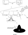
Figure 1 is a schematic diagram of an embodiment of a system for field or on-site tracking, identification or authentication of an industrial process material; -
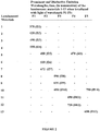
Figure 2 is a table depicting mutually different emission wavelengths for 13 luminescent materials; -
Figure 3 is a table depicting binary code representations of the presence or absence of mutually different emission wavelengths for 13 luminescent materials; -
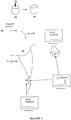
Figure 4 is a schematic diagram depicting tracking of a commodity chemical using trace incorporation of luminescent markers; and -
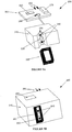
Figure 5A is a perspective exploded view of an integrated portable luminescence reader according to an embodiment of the present invention, whileFigure 5B is a perspective view of the reader ofFigure 5A in an assembled form. - As used herein the term "luminescent marker" refers to a material or mixture of materials which display fluorescence or phosphorescence (emission of light) as a result of a previous non-thermal energy transfer. Where, for example, a luminescent material is incorporated on and/or into an industrial process material according to any of the methods of the present invention, the industrial process material is said to be "marked" by the luminescent material. In this way the luminescent material is acting as a "luminescent marker" for that particular industrial process material. This marker may be selected from one or more luminescent materials which each provide a unique luminescent response when incorporated in and/or on the industrial process material. In this way the addition of the trace amount of the luminescent marker confers a unique identity to that industrial process material. The one or more luminescent materials respectively comprising the luminescent markers may be chosen to provide the unique identity by taking advantage of their unique luminescent profiles, for example, their excitation and emission frequencies and intensities A luminescent marker can therefore include one or more luminescent materials which individually or collectively have a unique luminescent emission and/or excitation profile.
- Examples of luminescent materials which may be used individually or in combination as a luminescent marker in the methods of the present invention include:
- a) Luminescent organic materials including the following:
Aromatic and heteroaromatic monomers, such as pyrene, anthracene, naphthalene, fluorescein, coumarin, biphenyl, fluoranthene, perylene, phenazine, phenanthrene, phenanthridine, acridine, quinoline, pyridine, primulene, propidinium halide, tetrazole, maleimide, carbazole, rhodamine, naphthol, benzene, ethidium halide, ethyl viologen, fluorescamine, pentacene, stilbene, p-terphenyl, porphyrins, triphenylene, umbelliferone, and their derivatives, such as, 9-anthracenylmethyl acrylate, 2-naphthylacrylate, 9-vinylanthracene, 7-[4-(trifluoromethyl)coumarin]acrylimide, 2-aminobiphenyl, 2-aminopyridine, bis-N-methylacridinium nitrate, diacetylbenzene, diaminobenzene, dimidium bromide, methylpyrene, 2-naphthol, 3-octadecanoylumbelliferone.
Fluorescent dyes known by trade names, such as Acid Yellow 14, Acridine Orange, Acridine Yellow G, Auramine O, Azure A and B, Calcein Blue, Coumarins 6, -30, -6H, -102, -110, -153, -480d, Eosin Y, Evans Blue, Hoechst 33258, Methylene Blue, Mithramycine A, Nile Red, Oxonol VI, Phloxine B, Rubrene, Rose Bengal, Unalizarin, Thioflavin T, Xylenol Orange, and their derivatives, such as Cresyl Violet perchlorate, 1,9-dimethylene blue, dodecylacridine orange bromide.
Polymers, such as fluorescent polymers, like poly(pyromellitic dianhydride-alt-3,6-diaminoacridine), poly((4,4'-hexafluoroisopropylidene)diphthalic anhydride-alt-thionin), light-emitting conjugated polymers, like polyfluorenyls, polyacetylenes, polyphenylene ethynelenes, and polyphenylene vinylenes.
Light-emitting dopant functionalised polymers, such as poly(9-anthracenylmethyl methacrylate), poly[(methylmethacrylates-co-(fluorescein O-acrylate)], poly[(methylmethacrylates)-co-(9-anthracenylmethyl acrylate)]. - b) Luminescent metal complexes including the following:
Metal complex emitters, such as zinc-, gold-, palladium-, rhodium-, iridium-, silver-, platinum-, ruthenium-, boron-, europium-, indium-, samarium-, and rare earth- complexes in general of a wide range of ligands, and their derivatives, such as bis(8-hydroxyquinolato)zinc, (2,2'-bipyridine)dichloropalladium(II), (2,2'-bipyridine)dichloroplatinum(II), chlorobis(2-phenylpyridine)rhodium(III), 8-hydroxyquinoline aluminium salt, lithium tetra(8-hydroxyquinolinato)boron, tris(dibenzoylmethane) mono(5-aminophenanthroline)europium(III), trichlorotris(pyridine)iridium(III). Other examples are provided in the following scientific papers: " Metallated molecular materials of fluorene derivatives and their analogues": Coordination Chemistry Reviews Volume: 249, Issue: 9-10, May, 2005, pp. 971-997; and " Luminescent molecular sensors based on analyte coordination to transition-metal complexes", Coordination Chemistry Reviews Volume: 233-234, November 1, 2002, pp. 341 - 350. - c) Phosphors (where the species below denote both doped, as well as undoped systems; that is, for example, CaS:Tb,Cl refers to CaS (undoped), CaS:Tb-doped, and CaS:Cl-doped) and includes the following:
Oxides, such as CaO:Eu, CaO:Eu,Na, CaO:Sm, CaO:Tb, ThO2:Eu, ThO2:Pr, ThO2:Tb, Y2O3:Er, Y2O3:Eu, Y2O3:Ho, Y2O3:Tb, La2O3:Eu, CaTiO3:Eu, CaTiO3:Pr, SrIn2O4:Pr,Al, SrY2O4:Eu, SrTiO3:Pr,Al, SrTiO3:Pr, Y(P,V)O4:Eu, Y2O3:Eu, Y2O3:Tb, Y2O3:Ce,Tb, Y2O2S:Eu, (Y,Gd)O3:Eu, YVO4:Dy.
Silicates, such as Ca5B2SiO10:Eu, Ba2SoO4:Ce,Li,Mn, CaMgSi2O6:Eu, CaMgSi2O6:Eu/Mn, Ca2MgSi2O7:Eu/Mn, BaSrMgSi2O7;Eu, Ba2Li2Si2O7:Sn, Ba2Li2Si2O7:Sn,Mn, MgSrBaSi2O7:Eu, Sr3MgSi2O8:Eu,Mn, LiCeBa4Si4O14:Mn, LiCeSrBa3Si4O14:Mn.
Halosilicates, such as LaSiO3Cl:Ce,Tb.
Phosphates, such as YPO4:Ce,Tb, YPO4:Eu, LaPO4:Eu, Na3Ce(PO4)2:Tb.
Borates, such as YBO3:Eu, LaBO3:Eu, SrO.3B2O3:Sm, MgYBO4:Eu, CaYBO4:Eu, CaLaBO4:Eu, LaALB2O6:Eu, YAl5B4O12:Eu, YAl5B4O12:Ce,Tb, LaAl3B4O12:Eu, SrB8O13:Sm, CaYB0.8O3.7:Eu, (Y,Gd)BO3:Tb, (Y,Gd)BO3:Eu.
Aluminates and Gallates, such as YAlO3:Eu, YAlO3:Sm, YAlO3Tb, LaAlO3:Eu, LaAlO3:Sm, Y4Al2O9:Eu, Y3Al5O12:Eu, CaAl2O4:Tb, CaTi0.9Al0.1O3:Bi, CaYAlO4:Eu, MgCeAlO19:Tb, Y3Al5O12:Mn.
Miscellaneous oxides, such as LiInO2:Eu, LiInO2:Sm, LiLaO2:Eu, NaYO2:Eu, CaTiO3:Pr, Mg2TiO4:Mn, YVO4:Eu, LaVO4:Eu, YAsO4:Eu, LaAsO4:Eu, Mg8Ge2O11F2:Mn, CaY2ZrO6:Eu.
Halides and oxyhalides, such as CaF2:Ce/Tb, K2SiF6:Mn, YOBr:Eu, YOCl:Eu, YOF:Eu, YOF:Eu, LaOF:Eu, LaOCl:Eu, (ErCl3)0.25(BaCl2)0.75, LaOBr:Tb, LaOBr:Tm.
CaS-type sulfides, such as CaS:Pr,Pb,Cl, CaS:Tb, CaS:Tb,Cl.
Miscellaneous sulfides and oxysulfides, such as Y2O2S:Eu, GdO2S:Tb, Na1.23K0.42Eu0.12TiSi5O13:xH20:Eu.
Lamp and cathode ray tube phosphors, including rare-earth doped phosphors.
"Up-converters" or compounds that emit photons of higher energy than they absorb, such as NaYF4:Er,Yb, YF3:Er,Yb, YF3:Tm,Yb. - d) Quantum-dots or nanoparticulate materials whose luminescent properties are dependent on their particulate size, such as gold and other metal nanoparticles.
Due to the cost associated with many of the luminescent materials described above, their natural presence in industrial process materials is rare which makes them suitable candidates as markers.
Furthermore, the luminescent marker is suitably selected from one or more luminescent materials which do not adversely affect the physical properties or react with the industrial process material either during process manufacture or during storage, transport or in use. To ensure that the marker remains inert with respect to the industrial process material the luminescent materials which comprise the marker may be chemically or physically modified. For instance, the luminescent marker may be composed of one or more luminescent materials which are physically encapsulated within a covering sheath. The sheath may be composed of a polymer, such as methylmethacrylate, polypropylene, polyethylene, or polystyrene or a wax such as paraffin wax, beeswax, gel wax, vegetable wax or the like. Methods of encapsulating luminescent materials with polymers and waxes are known in the art.
For industrial process materials having long life-cycles, the one or more luminescent materials used in the luminescent marker should be selected to be those which do not degrade easily over time and therefore can be tracked for long periods. Examples of longer-lived luminescent materials potentially suitable for use as a luminescent marker may include Ag-activated zinc sulfide, Mn-activated magnesium fluorogeminate (in surface settings, exposed to sunlight), pyrene and anthracene (within the body in bulk settings, not exposed to sunlight). The luminescence properties of these luminescent materials degrade slowly over time so that they can be reliably and reproducibly detected over extended periods of time which substantially or at least partially correspond to the duration of the average life-cycle of the associated industrial process material.
As used herein the term "industrial process material" includes, but is not limited to the following classes of materials:- a) Materials used for construction, including:
- Concrete
- Cement
- Timber
- Treated timber
- Clays and Clay Products
- Glass
- Structural plastics and polymers
- Decorative plastics and polymers
- Sealing plastics and polymers
- Composite materials
- Ceramics
- Metals and metal alloys
- Gypsum
- Bitumen
- Asphalt and asphaltic concrete
- Paint
- Corrosion protection materials, such as paint
- Silicon
- Structural textiles
- b) Materials used for structural and non structural applications in transportation vehicles, including motor vehicles, motorcycles, boats, air-transportation vehicles, and the like, such materials including:
- Rubber, vulcanised rubber and their compounds
- Silicon
- Plastics
- Composite materials
- Epoxy
- Ceramic materials and ceramic composites
- Compounded materials such as, but not limited to, brake pads
- Adhesive, glue, (vehicle) cement
- Metal and metal alloys
- Glass
- Polycarbonate
- Paints, undercoats and primers
- Finishing products such as abrasive compounds, polishes and sealants
- Antifouling materials and compounds
- Low friction materials and compounds
- Antistatic compounds
- Lubricants
- Cooling materials and compounds
- Hydraulic fluids
- Anti corrosion additives and compounds
- Textiles
- c) Materials used for industrial manufacturing of goods, components, clothing, and chattels, including:
- Plastics and polymers and composites used as substrates for removable media such as, but not limited to memory cards and electronic chips
- Plastics and polymers and composites used as base materials for computers, phones, batteries, and plastic utensils and components, toys
- Glass
- Composite materials for structural purposes
- Epoxy
- Glue
- Ceramics
- Semiconductors
- Textiles
- d) Materials used in the industrial manufacturing of computers and information technology-based items, including:
- Ceramics
- Plastics
- Polymers
- Composite materials
- Components such as circuit boards, processors and memory chips
- e) Materials used for large-scale industrial packaging of goods, components, and chattels, including:
- Paper
- Cardboard
- Plastics
- Textiles
- f) Materials used in primary and energy industries, including:
- Bulk materials used as commercial commodity chemicals and commodity materials Propellants
- Energetic materials
- Politically sensitive materials and chemicals
- Cyanide
- Precursor chemicals
- Nuclear materials
- Aggregates
- Ores and processed and semi-processed ores
- Ammonium nitrate
- Other nitrates
- Pesticide, herbicides and other potentially dangerous materials Soil conditioners
- Scrubbing agents
- Mineral and agricultural commodities that are exchanged on commodity trading floors
- g) Materials used in miscellaneous industrial manufacturing, including:
- Pharmaceuticals and their precursors
- Food additives and products
- Cosmetics
- Alcohol
- a) Materials used for construction, including:
- Accordingly, from the above list it can be seen that an industrial process material may be a standardised and/or undifferentiated solid, liquid or gaseous medium having a low inherent visual identity. The industrial process material may also include a mixture of two or more industrial process materials.
- Depending on when the luminescent marker is added during the manufacturing procedure, the luminescent marker may be incorporated into the industrial process material or incorporated on the industrial process material. For example, where the industrial process material is produced as a solid the luminescent marker may be added and mixed with the industrial process material after its production. In this way the luminescent marker may coat the surface of the industrial process material (or a portion thereof) and therefore is incorporated "on" the industrial process material. An instance where the luminescent marker may be said to be incorporated "into" an industrial process material is where the luminescent marker is added during a process step and is located within the final material. A further example is where the luminescent marker is added after the production of an industrial process material in a manner in which it penetrates into the industrial process material.
- Accordingly, the luminescent marker may be incorporated into and/or onto industrial process materials by physical incorporation and/or chemical incorporation. For example, physical incorporation may involve the physical trapping of luminescent dye molecules, particles, or aggregates, within the structure or structural make-up of a bulk material. Specific examples of physical incorporation include: the seeding of wet cement with microparticles of line phosphors prior to its casting; the driving of molecular luminescent dyes into the pore structure of timber under elevated pressure; and the suspension or dissolution of luminescent dyes in liquefied forms of commodity chemicals and preservatives.
- Chemical incorporation may involve the creation of an attractive interaction between luminescent dye molecules, particles, or aggregates and the bulk material itself. Specific examples of chemical incorporation include: the adsorptive binding of molecular dyes to threads and yarns; the ion-paring of cationic luminescent dyes to negatively charged silica particles within the sand fillers used in cement; and the formation of attractive π-π interactions between aromatic dyes and bulk materials containing aromatic chemical groups.
- In order for the luminescent marker to act as an effective marker for the methods of the present invention it must be present in detectable amounts. As used herein the term "trace amount" refers to an amount of luminescent marker which is present or required only in a minute amount so as not to be optically detectable in the presence of ambient light. Preferably, the amount is between 1 part per billion and less than 1% by mass of the industrial process material. It will be appreciated that the trace amount of the luminescent marker will exhibit fluorescence or phosphorescence but is not present in amounts which will cause the industrial process material to visibly fluoresce or phosphoresce under ambient light. Accordingly, the incorporation of the luminescent marker on or into the industrial process material according to the methods of the present invention does not provide the industrial process material with any visual identity when observed by the naked eye. As such, the presence of the luminescent marker does not affect the normal physical appearance of the industrial process material.
- The methods of the present invention include the addition of luminescent markers which may be composed of a multitude of luminescent materials. Preferably when multiple luminescent materials form the luminescent marker the luminescent materials are selected such that these produce discrete electronic transitions (emission spectrum) and/or display varying intensity at these transitions. The use of such multiple luminescent materials enables the development of a versatile and dense encoding scheme whereby the characteristic emissions produced by the multiple luminescent materials incorporated on or into an industrial process material enables the identification of the material.
- For example, one encoding scheme involves the addition or incorporation within the industrial process material of a luminescent marker comprising one or more luminescent materials in a variety of quantities to thereby impart the industrial process material with a unique luminescence spectrum. This spectral fingerprint may be exceedingly complex and detailed. As such, this unique spectrum may serve as a "fingerprint" that identifies the industrial process material. Such a spectrum may be stored in a digital form within a database library of such spectra and subsequently recognised from amongst this library by a suitable matching algorithm. Since the constituents and relative quantities of the luminescent materials in luminescent markers in such a spectral fingerprint can be varied in an almost unlimited number of ways, it follows that an extremely large number of codes can be devised to mark industrial process materials using this technique.
- Another exemplar encoding scheme provides N number of luminescent materials as a luminescent marker (each having a discrete electronic transition), each having M distinguishable states, such that Mn different states can be uniquely defined. In the case of M=2 where the two states could be the presence or absence of the luminescent material, the encoding scheme would thus be defined by a
base 2 or binary code. In the case of M=3 where the three states could be the presence of a luminescent material at two distinguishable intensities or its absence, the encoding scheme would be defined by abase 3 code or tertiary code. Accordingly, higher codes can be formed which have the advantage over a binary order code in that fewer luminescent materials would be required to encode the same quantity of information. - A further exemplar method for coding involves using luminescent markers which impart the industrial process material with one or more unique qualities that are observable only under very specific conditions of measurement or detection. For example, luminescent markers may be used which emit highly distinctive spectra only under very particular conditions of temperature, pressure, concentration, solvation, vapour, magnetisation, or similar external physical condition. Under such a condition of observation, a distinctive spectrum is observed, or combined spectra are observed, and used to encode an industrial process material with a unique identity. Other examples in this respect include, but are not limited to the use of luminescent markers that: (i) emit light of particular polarisation or of particular anisotropy when irradiated with light having a particular polarisation or anisotropy (including light of no discernible polarisation or anisotropy), and (ii) glow with a particular spectrum or intensity profile when irradiated with light of one or more particular frequency and intensity profiles that are subjected to a particular, carefully controlled pulsing sequence.
- A wide range of other encoding techniques may be used to impart industrial process materials with unique identities by the incorporation onto or into them of luminescent markers each of which can selectively comprise one or more luminescent materials.
- The use of such codes in the methodology of the present invention provides identity to industrial process materials which ordinarily lack identity. This enables life-cycle tracking of the industrial process material which is especially important in monitoring the presence of those industrial process materials which are prone to being disposed of improperly or illegally at the end of its useful lifetime and may cause environment pollution. Tracking in this way also enables manufactures, consumers and law enforcement agencies to monitor any illicit trade in an industrial process material or illegal substitution for inferior materials which may affect manufacturers warranties and may also provide useful information when building a case to prosecute offenders.
- It will be appreciated that the life-cycle tracking method will involve a step of identifying the industrial process material during a plurality of life-cycle stages, for example, at the point of manufacture to confer identity to the material, and after delivery to confirm that the material has not been substituted in transit. Also, the industrial process material may undergo processing to produce a product. The product can be a commodity product which, like the industrial process material, is standardised undifferentiated, substitutable, interchangeable, batch-processed in essentially identical form and available in bulk, or the product may be a high-value article. Accordingly, the life-cycle tracking method may involve an identifying step which involves detecting the luminescent marker in a commodity product or high-value product. Preferably, the method is used to track the industrial process material or the industrial process material and commodity products derived therefrom. Also it will be appreciated that once the industrial process material is transformed into a product, the detection of the luminescent marker will need to be performed on that product, if required.
- This is generally conducted by removing samples of the product for analysis in a laboratory setting. The advantage of using embodiments of the portable reader system of the present invention however means that the luminescent marker can be detected in situ in the field, non-invasively, that is, without damaging the product.
- Luminescent materials have previously been proposed for use in testing of biological materials. The methods of the present invention do not use the luminescent marker to biologically test the industrial process material.
- A further advantage of embodiments of the methods of the present invention resides in stock control where large volumes of industrial process materials are produced on a daily basis. Again, because industrial process materials are inherently difficult to differentiate from one batch to the next, it is also difficult to conduct stocktakes and thus account for all the material produced. By adding unique luminescent codes to different batches of an industrial process material the whole stock control process may be modularised. This would be particularly important for the production of dangerous chemicals where it is a legislative requirement to account for all material produced and to provide information to the relevant authorities as to the whereabouts of the material at any given time.
- A further related advantage of embodiments of the present invention resides in process control. For instance, in modularising the stock control process, as discussed above, it is easier to locate batches of a particular industrial process material which may be defective due to a processing error. Where procedures for preparing a particular industrial process material involve multiple process stages, process monitoring at each stage can be accomplished by adding a distinct luminescent marker during a particular process stage. In this way the quality of the final material can be accessed on a stage by stage basis whereby the efficiency of each stage can be monitored and process parameters varied if required.
- Other more specific applications of the methods of the present invention are as follows:
- To aid unambiguous batch and producer assignment in large concrete structures containing multiple batches, possibly from different manufacturers, a multiplicity of different luminescent materials in different quantities to form the luminescent marker may be employed to generate diverse and complex codes of the types described above in order to distinguish the different batches of concrete. As the strength of poured concrete can only be determined after an extended time of drying (typically 3 months), concrete batches that do not come up to specification can be accurately found, delimited, and replaced if required.
- A piece of timber can be treated such that a luminescent marker consisting of one or more luminescent materials is incorporated into the timber during preservation treatment. Thus, a piece of wood present in the frame of, say, a house can at any time be examined to assess the type of treatment used, and the success of the treatment both externally and internally. Moreover, the luminescent marker may be used to provide an indication of the treating company or of the plantation from which the timber originated, or of any other desirable variable.
- More detailed information about the timber, its treatment, its origin, and its handling may be embedded through the use of coded combinations of a multiplicity of different luminescent materials. For example, to aid unambiguous batch, producer, or plantation assignment, diverse and complex combinations of multiple different luminescent dyes, as discussed above, may be added to preservatives and treated timber.
- A freshly extracted mineral ore, for example iron ore, may be marked by spraying with a suitable solution of a luminescent marker. Trace amounts of the luminescent marker may permeate and/or stick to the ore marking it unambiguously. The ore may subsequently be loaded, piecemeal, onto railway cars for transportation to an ore processing centre. The processing centre may be used by other mines. After the railway journey, the ore may be deposited in an ore field containing ores of all of the other mines. As the ore from separate mines may be required to be processed under slightly different conditions, it may be important to keep track of the origin of each ore batch. Immediately prior to processing, the ore can be therefore tested to confirm the presence of the luminescent marker, thereby identifying its origin and its optimum processing conditions. The processing technique is subsequently optimised for efficiency when treating the marked ore.
- This process may be adapted to provide more detailed information regarding the particular batch of ore, such as the date, time, and the precise location (ore body) within the mine from which the ore was obtained. This may be achieved by spraying the ore with a solution of a luminescent marker incorporating various coded combinations of a multiplicity of luminescent materials as described above, and assigning each batch a unique identifying address.
- A luminescent marker consisting of one or more luminescent materials may be selected which binds strongly to natural or synthetic fibres, threads, yarns, and the like. Within a particular dyeing plant, the luminescent marker may be incorporated at low levels within the dyes used to colour yarns, threads, and the like. It is preferred that when treated with these dyes, the yarns and threads bind the luminescent marker strongly. Using the portable reader of the present invention, the presence of the luminescent marker upon the fibres, yarns, or threads, may be unequivocally and unambiguously determined.
- Alternatively, synthetic fibres may be produced under conditions in which a particular luminescent code or codes are incorporated as an integral part within the fibre. For example, synthetic fibres may be extruded or drawn such that they contain within them a mixture of one or more luminescent materials which provide a luminescent code or codes to identify them. Such fibres may subsequently be spun into yarns or threads and the like. Such yarns or threads may be incorporated at various levels and in various ways within fabrics or materials, where they may act as "marker fibres"; that is, where they act to provide the overall fabric or garment with an identity, a batch number, or similar property.
- The above processes may be adapted to provide rudimentary or detailed information as required, including information regarding the origin and handling of the particular batch of fibres, yarns, threads, or information regarding the dye used, such as the date and time of dying, the dye manufacturer, and the dye batch number. This may be achieved by incorporating a luminescent marker consisting of a multiplicity of luminescent materials, as described above, within the dyes or within the fibres employed and assigning each combination of luminescent materials with a unique identifying address. In this way detailed information regarding, for example, the processing conditions, the dyes used, the dyeing plant employed, the fibre manufacturing technique, the fibre manufacturer, the fibre handling procedure, and the owner, manufacturer, or brand holder of the fibres, yarns, or threads, may be encoded into the materials.
- Luminescent markers respectively consisting of one or more luminescent materials approved for use as food additives may be incorporated within or upon foods or food products, or within or upon mass-produced medicines or pharmaceuticals. The trace incorporation of the luminescent marker may be used to provide rudimentary or detailed information, as required, regarding these industrial process materials, including information about the material, for example, the date and time of manufacture, the batch number, the method of manufacture, the method of packaging, and the identity of the manufacturer. This may be achieved by assigning each combination of the luminescent materials comprising the luminescent marker with a unique identifying address. This address may be connected to the above details in a database. Subsequent health and safety issues relating to a particular food, medicine or pharmaceuticals containing the luminescent materials may be investigated using information unambiguously embedded within the material.
- Because of the risk of diversion for nefarious end, materials capable of being used in bomb-making must be closely monitored at all stages of their production, distribution, warehousing, and up to and including the point of their physical use and conversion into a form suitable for bomb-making. Such supplies, include a wide diversity of potentially explosive materials, ranging from military explosives, such as plastic explosives, through to fertilisers, such as ammonium nitrate. A key problem in this respect is distinguishing one sample of an explosive or potentially explosive material from another, identical sample. Thus, the physical production of an explosive (or potentially-explosive) material entails producing multiple, identical samples, which are collectively stored, counted, and distributed. Because each sample is identical to the next, a high possibility exists that it could be double-counted during stock-taking, or that it is not counted at all, thereby readily allowing for its unauthorised diversion to be undetected. Alternatively, it could be diverted for nefarious ends immediately after manufacture and prior to the first stocktaking, thereby resulting in its presence or absence not being recognised. In such cases, the diverted sample of the explosive material may be regarded or treated as though it was never produced. Another possibility is that a sample of the explosive material which has been diverted for nefarious purposes, may be replaced with an identical looking dummy material, whose non-explosive properties are not detected until very much later, by which time it is impossible to determine where in the manufacturing and distribution chain it was diverted. All of these possibilities arise because any one sample of the explosive material is indistinguishable from the next.
- A solution to this difficulty is to provide each sample of the explosive or pre-explosive material with a unique identity, incontrovertibly embedded within all portions of the sample at the point of manufacture. This may be achieved by incorporating within the explosive material a luminescent marker which consists of a multiplicity of luminescent materials as described above, and assigning each combination of luminescent materials with a unique identifying address. In this way, each individual sample is infused, in a non-reversible way, with an address that distinguishes it from the next. During the production of the explosive or potentially explosive material, each subsequent sample may be provided with a new address in accordance with a pre-determined sequence of addresses. Where applicable, the addresses may be generated within the sample using an automated process in which trace amounts of luminescent markers, each comprising one or more preselected luminescent materials, are automatically added, according to a predetermined sequence, to the samples during manufacture. In this way, the sequence of addresses is therefore immune from human tampering.
- Stocktaking may be undertaken at any stage in the manufacturing, warehousing, distribution, or subsequent logistical procedure, up the point of usage or of conversion to a form that is not suitable for bomb-making. Stocktaking may be modularised in that it involves checking whether all of the expected addresses are present. The absence of any one address immediately and unambiguously indicates an error whose origin can be directly and unequivocally pinpointed and investigated. Thus, double-counting or under-counting during stocktaking can be avoided or minimised. Moreover, diversion immediately after manufacture and prior to the first stocktaking is also prevented, as is substitution with a dummy material. By storing and monitoring the movement of each address, it is possible to monitor the distribution chain of each sample and determine whether it is ever diverted and, if so, to where it is diverted. In this way, weak links in the distribution chain can be readily identified and eliminated, thereby ensuring integrity in the distribution chain.
- The application of the above process would be optimally achieved using a luminescent marker including one or more luminescent materials that are highly compatible with explosive materials in that they do not change the key physical properties of the explosive materials or react with these materials. Vacuum stability and friction sensitivity tests may be employed to assess the suitability of luminescent markers respectively comprising one or more luminescent materials for tracking explosive materials.
- Aerosol-type spray paints are widely used in the illegal creation of graffiti, a form of vandalism in which paint is applied to an object owned by another. In order to hinder graffiti and identify the perpetrators of such vandalism, individual cans of spray paints may be made to incorporate a luminescent marker consisting of one or more different luminescent materials in forensic quantities, so as to provide each individual can with a unique identifying address of the type described above. By maintaining a register of the purchasers of individual aerosol spray-paint cans, and by determining the address of the paint employed in the creation of graffiti (using the reader described above), it becomes possible to identify the individual can of spray paint used and also the individual who purchased it. In this way, it becomes possible to monitor the distribution chain of each individual can of spray paint to monitor, detect and prevent its illegal usage.
- Furthermore, aerosol-type spray paints and lacquers may be used as a means of identifying the owner of fixed assets, such as scaffolding, tables and chairs, computers, and office furniture in general. At any stage in the future, the origin and owner of the asset can be determined by simply detecting the presence of the luminescent marker.
- Industrial metals present special problems when it comes to marking due to the fact that their properties often depend on the presence of exceedingly small amounts of trace materials present in the alloy matrix. Incorporating even forensic or trace amounts of luminescent markers each including one or more luminescent materials, into a metal alloy may interfere with the desired properties of the metal. Furthermore, the bulk properties of metals are also greatly influenced by their crystal structure and crystal orientations. Once again, incorporating even forensic or trace amounts of a luminescent marker comprising one or more luminescent materials or other particles into the alloy matrix can interfere with the desired crystalline structure of the metal and influence the properties of the bulk metal in an undesirable way.
- For these and other reasons, it has, until now, generally not been possible or cost-effective to readily incorporate luminescent materials into or onto metals because incorporating such materials throughout the metal matrix would have deleterious and unpredictable effects on the alloy matrix or on the crystalline properties of the metal or the metal alloy. Additionally, the luminescent properties of most luminescent materials are themselves typically degraded when they are physically incorporated into molten metals during their forming process.
- However, techniques are now commercially available by which particles may be embedded into or onto the surface of metals by imparting them and their carrier media with specific ranges and combinations of kinetic and thermal energies. Such ranges of combinations of kinetic and thermal energies are typically, but not necessarily exclusively, created in industrial thermal and cold spray type processes. In these techniques, particles are, effectively, accelerated to high velocity and are then made to collide with a metal or metal alloy surface. The process of the collision embeds, impregnates, welds or otherwise affixes or attaches the particles to or in the surface, or near the surface of the metal or metal alloy. Such spray processes currently exist in the commercial environment where they are typically used for spraying materials onto metals for coating purposes, to replace electrolysis or to create other coatings that protect against oxidation, corrosion and wear. For example, commercially available cold spray (or cold gas-dynamic) technology can produce coatings with a gas-jet temperature that is lower than thermal spray processes such as powder flame, wire arc, plasma arc and high-velocity oxygen fuel spraying.
- Such metal coating technology can be used to embed luminescent markers each consisting of one or more luminescent materials into metals and onto their surfaces by imparting them and their carrier media with specific kinetic and thermal energies. Although many luminescent materials are friable, meaning that their properties are typically degraded by stresses, such as the sheer stresses that are created in collisions, it has been found that many luminescent materials can be impacted or coated onto a metal using cold spray technology in such a way that they retain their luminescent properties without significant degradation.
- Cold spray technology is therefore an example of a suitable conventional metal coating technique that can be used for incorporating, integrating, impregnating, welding or otherwise affixing or attaching luminescent markers each comprising one or more luminescent materials to metals in a way that has no significant deleterious effects to the metal or metal alloy's crystalline structure, or to the metal or metal alloy's thermal history. The key required mechanical properties of the metal are therefore unaffected by the marking process.
- Moreover, such kinetic and thermal attachment methods may, additionally, be applied after the metal has been manufactured in a particular industrial process. For example, marking of this type may be applied to metal aircraft parts after their manufacture. This allows parts to be marked individually, in batches, or in any other format that may be desired.
-
Figure 1 illustrates asystem 100 for field or on-site tracking of aluminescent marker 1 incorporated in and/or on anindustrial process material 7. When theluminescent marker 1 is irradiated with light of wavelength F1, it glows with thespectrum 2, containing the unique wavelength f11. In order to detect the presence of theluminescent marker 1 incorporated in or on anindustrial process material 7, thematerial 7 is irradiated with F1 and any light emitted by thematerial 7 is collected and examined to see if it contains light of wavelength f11. To perform such an operation, aportable luminescence reader 3 can be used. In thereader 3, alight source 4 generates light of wavelength F1 when prompted by an attachedcomputer 12. Thecomputer 12 includes at least one processor (not shown) and processor instructions executable by the at least one processor. Optionally, thelight source 4 may also generate light of other wavelengths F2, F3, F4 ... Fm upon command by thecomputer 12. The light generated by thelight source 4 is, optionally, collected and transported by a fibre optic or a bundle of fibreoptic elements 5. Alternatively, thereader 3 may be so constructed that a fibre-optic collector 5 is replaced by a line-of-sight arrangement in which light is delivered directly to thematerial 7 by thelight source 4. - At the head of the fibre optic or fibre optic bundle 6 (or at the reading aperture in the case where a line-of-sight arrangement is used), the light of wavelength F1 exits and falls upon the
material 7 which contains trace amounts of theluminescent material 1. Because only trace (or forensic) amounts of theluminescent material 1 may be present in thematerial 7, it may glow only exceedingly weakly - far more weakly than even a small fraction of ambient light. Because ambient light may interfere with the detection process, it is excluded on each occasion that thereader 3 is used. This is achieved by fitting the head 6 (or the reading aperture) of thereader 3 with theelastomeric cap 6a (or shroud), which is so constructed that when the reader head is pressed up against any solid or particulate surface of thematerial 7, it moulds itself to the shape of the surface and substantially blocks all ambient light from entering the area immediately between thereader head 6 and thematerial 7. Any resulting glow emitted by thematerial 7 is collected by a second fibre optic or bundle of fibreoptic elements 8 present in thehead 6. These transport the collected light to aspectrometer 9, containing a suitable light-sensitive element 10 which is capable of detecting the presence of wavelength f11. - The
spectrometer 9 can be any conventional instrument capable of detecting a particular frequency of light emitted by thematerial 7. Such an instrument can include, for example, at least the following elements: (a) a light-sensitive element 10 capable of electrically registering the presence of incident light; and (b) a frequency-controlling element capable of limiting, specifying, or controlling the frequency of the incident light. Examples of the light-sensitive element 10 include, for example: (a) a fluorescence spectrometer or similar device; (b) a suitable CCD chip or similar device; (c) a photodiode or similar device; (d) a photomultiplier tube or similar device, (e) a semiconductor or similar material capable of generating an electrical response when irradiated with light of selected frequency; and (f) a photoactive chemical capable of signalling the presence of light of a selected frequency in any way. Examples of the frequency-controlling element include, for example: (a) prisms and slits which disperse and separate the incident light into its constituent frequencies which can then each be measured separately; and (b) band-pass, cut-off, or other filters which selectively allow the passage of only certain frequencies of light, thereby allowing selective examination of these frequencies only. - The light-
sensitive element 10 transmits measured data alongcable 11a to an interfacedcomputer 12 which computes the spectrum or the detected frequency and determines whether theluminescent marker 1 is present based on the presence or absence of light having wavelength f11. Thecomputer 12 may repeatedly switch on and switch off the light source 4 (usingcable 11b) each time checking the presence or absence of a signal at the light-sensitive element 10 due to emission wavelength f11. Thecomputer 12 may therefore mathematically verify the measured observation by repeating it or integrating the data. Thecomputer 12 may also switch on and off thelight source 4 at different times that it collects data from the light-sensitive element 10, thereby eliminating spurious or background data or generating a distinctive response or pattern of responses which is unique to the luminescent marker used. - As illustrated in
Figure 1 thereader 3 may be implemented using, for example: (i) a laptop computer or a personal digital assistant (PDA) 12 and appropriate wired orwireless connections 11; (ii) a USB2000 miniaturisedspectrophotometer 9 supplied by Ocean Optics (Dunedin, Florida, USA) and (iii) a VSL-337 miniaturisedultra-violet laser 4 supplied by Laser Science Inc. and fitted with a fibre-optic connector 5. - Alternative
light sources 4 can include, for example, one or more of the following: (i) light-emitting diodes (LEDs) operating at 250-365 nm, the latter being supplied by Nichia Corp., Japan, (ii) a PX2 pulsed Xenon light source supplied by Ocean Optics; and (iii) commercially available LEDs capable of generating a variety of visible and infra-red irradiation in the range 365-1100 nm. A variety of other solid state or incandescentlight sources 4 may be employed. The light source may optionally be incorporated within the light-excluding elastomeric cap. A pulse generator, such as a Datapulse 100A supplied by Systron-Donner Corp., and a LED or other activating circuit may optionally be placed between thelaptop computer 12 and thelight source 4 in order to generate well-controlled light pulses. -
Optical fibre cable 6 can be implemented, for example, as a QBIF400-UV-VIS, 400 micron thick bifurcated optical fibre cable supplied by Ocean Optics to carry exciting and emitted light. The fibre optic cable contains two layers of optic fibres; aninner bundle 5 around which is arranged anouter bundle 8. The terminus of the outer bundle is plugged into the fibre optic fitting on the laser. The terminus of theinner bundle 5 is plugged into the fibre optic fitting on thespectrophotometer 9. At the head of thefibre optic cable 6, the two fibre optic bundles are combined in a so-called "reflection probe". A reflection probe typically consists of a metal assembly which envelopes the two fibre optic bundles and provides a small lip beyond the end of the fibre optic. This lip can be angled (for example, at 30 degrees) when wanting to make measurements at these angles. In operation, reflection probes are held tight up against the sample to be analysed; the purpose of the lip is to eliminate as much of the external ambient light in the space between the fibreoptic head 6 and thesamples 7 as possible. Because the lips on reflection probes are metal, they can generally not provide a perfectly complementary fit with a sample surface. As such, they are unable to block out all of the ambient light present in the space between thereader head 6 and thesample 7. To combat this difficulty, manufacturers of such probes also supply large anodised aluminium blocks containing suitable receiving holes into which the reflection probes may snugly slide; these aluminium blocks are called "reflection probe holders". By virtue of their size (typically a 7 cm x 4 cm footprint), these holders further block out the ambient light, but again not all of it. - To substantially eliminate the presence of ambient light and make possible the use of trace (or forensic) quantities of luminescent markers consisting of one or more luminescent materials, a light-excluding
cap 6a made of a heavy rubber, is attached to the reader head 6 (or to the reader aperture in the case where a fibre-optic connector is not used). Thecap 6a consists of a, black, conically-shaped rubber sleeve into which the reflection probe 6 (or the reader aperture) is pushed. The sleeve of thecap 6a fits thereflection probe 6 tightly. Near the bottom of the cone-like rubber sleeve of thecap 6a, a second, broader rubber cone is attached. This cone contains a series of concentric, circular rubber lips, each of which is capable of blocking out ambient light when the reader head is pressed against a sample surface. Therubber cap 6a eliminates ambient light during the measurement process. - The operation of the
reader 3 may be controlled using OOIBase32 (trade mark) or OOIChem Spectrometer operating software supplied by Ocean Optics. Alternatively, bespoke software may be used to control the operation of thereader 3. The software switches thelaser 4 on and off, and collects and processes the data received from thespectrometer 9. Theentire reader 3, including a controlling PDA computer and its battery, fits into a shoebox-sized volume making thereader 3 fully portable. Therubber cap 6a on thereader head 6 allows the reader to be routinely used in field operation, permitting reliable and ready, in-situ, determination of forensic quantities of luminescent materials present in industrial process materials. Therubber cap 6a facilitates such traceability. For example, theVSL laser 4 described above produces light of power approximately 10 microjoules per pulse. Using thislight source 4 and thereader 3 and therubber cap 6a, it is possible to detect, in routine field measurements, certain luminescence markers present in concentrations of 1-10 parts per million in commercially available concrete. This could not be achieved without substantially total exclusion of all ambient light. - The
reader 3 may employ a detection algorithm (or protocol) to detect the presence of the luminescent marker inmaterial 7. Numerous possible detection algorithms can be formulated. In one exemplar detection algorithm, the characteristic emission spectra of a plurality ofluminescent markers 1 employed in thesystem 100 are stored in a database stored in thecomputer 12. By referring to the database, it is possible to identify the particularluminescent marker 1 present in anindustrial process material 7. Thus, for example, when irradiated with light of frequency F1,luminescent marker 1 emits light having the spectrum shown in 2. This spectrum may be stored in a digital form in thecomputer 12 database asspectrum 2a. This database also contains the emission spectra of various other luminescent materials which comprise predeterminedluminescent markers 7. When theindustrial process material 7 is irradiated with light of frequency F1, it produces a spectrum. This spectrum is compared by the algorithm to each of the database spectra. If the observed spectrum fits 2a (within an expected variability range), theindustrial process material 7 must clearly containluminescent marker 1. By this means it becomes possible to detect the presence of a trace amount of a particular predeterminedluminescent marker 1 within anindustrial process material 7. This process may be repeated for various other combinations ofluminescent markers 1 andindustrial process materials 7. - Alternatively, the
emission spectrum 2 may contain a distinctive and unique peak at frequency f11 which is not emitted by any of the otherluminescent markers 1 in thesystem 100 upon illumination with light of frequency F1. The detection algorithm may operate by associatingluminescent marker 1 with the presence of this peak in the emission spectrum resulting from irradiation with light of frequency F1. Thus, the detection algorithm may examine using conventional spectral matching techniques whether a peak of a particular intensity is observed at frequency f11 when theindustrial process material 7 is illuminated with light of frequency F1. The presence of such a peak validates the presence ofluminescent marker 1. The process may be repeated for otherluminescent markers 1 comprising one or more luminescent materials having unique emission peaks. - The simultaneous presence in a
luminescent marker 1 of a multiplicity of constituentluminescent materials reader 3 may be configured to carry out a routine in which the illuminating wavelength is sequentially changed to other wavelengths F2, F3, F4 ... Fm, each of which cause one or more of a multiplicity of luminescent materials 1-n to glow with distinctive wavelengths, fm1, fm2, fm3, fm4,...fmn. Each luminescent material 1-n incorporated within theluminescent marker 1 of theindustrial process material 7 in such a case may glow with at least one prominent and unique wavelength fmn when illuminated with light of a single wavelength Fm, but will not glow when irradiated with light of the other wavelengths Fm.Luminescent markers 1 comprising luminescent materials glowing with multiple wavelengths under multiple irradiation wavelengths can be used provided that their emissions are mutually non-interfering. -
Figure 2 depicts the emission properties of an example set of luminescent materials 1-13 which may be selectively used individually or in different combinations as aluminescent marker 1. Luminescent materials 1-4 glow strongly with distinctly different wavelengths when irradiated with F1, but do not noticeably glow when irradiated with F2-F5. Similarly, luminescent materials 6-7 glow distinctively when illuminated by F2, but not under any of the other irradiating wavelengths. Luminescent materials 8-9 glow effectively only when irradiated with F3 and their distinctive emission wavelengths are significantly different. Materials 11-12 emit, distinctively, only when irradiated with F4, whilematerial 13 glows strongly only when irradiated with F5.Luminescent materials - By sequentially irradiating a sample of an
industrial process material 7, which may contain aluminescent marker 1 consisting of a mixture of luminescent materials 1-13, with the wavelengths F1-F5 and determining the presence or absence of each of the expected wavelengths fmn, it is possible to determine which of the luminescent materials 1-13 are present. Since the presence or absence of each luminescent material provides a binary code (0 = absent, 1 = present), many combinations of these luminescent materials are possible. In this way, industrial process materials may be allocated a unique "address" (or code) which distinguishes them from all of the other possible addresses, thereby allowing differentiation of numerous, otherwise identical items marked withluminescent markers 1 comprising the luminescent materials 1-13. -
Figure 3 depicts a exemplar matrix of binary codes (or "addresses") deriving from the presence or absence of the above 13 different luminescent materials which make up theluminescent marker 1. Given that the absence of all of the luminescent materials does not provide unambiguous information, one of the luminescent materials must always be present; this material will ideally be a rare material, not freely available, and whose properties are not mimicked by any other luminescent material. In the example depicted inFigure 3 , constituentluminescent material 1 is chosen to be always present. As this material is not widely and generally available, it serves as a reference marker of the use of the technique. In the case of an industrial process material containing trace amounts of all 13 of the luminescent materials, the binary code 1111111111111 is generated, and this becomes the unique address for that industrial process material. If all butluminescent material 2 are present in another industrial process material, its address is 1011111111111. If all butluminescent material 3 are present in a further industrial process material, this provides it with the binary code address 1101111111111. This approach provides many different possible binary codes, thereby allowing differentiation of a large number of different industrial process materials, each marked with aluminescent marker 1 consisting of a different combination of the luminescent materials 1-13 and each having its own address. - The
reader 3 as depicted inFigure 1 may also be programmed to detect and compare the intensity of the emitted glow of one or more luminescent materials selectively comprised in theluminescent marker 1, according to an algorithm suitable to perform a particular process, quality, or logistic control task or tasks. Such an algorithm may involve measuring the digital amplitude of the signal received at a series of "expected" wavelengths in the ultra-violet, visible and infra-red regions when the light source is activated (or immediately thereafter, if it is pulsed). The "expected" wavelengths are those wavelengths at which any deliberately incorporated luminescent materials will glow strongly. For example, in the case ofFigure 2 , the expected wavelengths are: f11, f12, f13, and f14 when illuminated with F1, f25, f26, and f27 when illuminated with F2, f38, f39, and f310 when illuminated with F3, f45, f411, and f412 when illuminated with F4, and f510 and f513 when illuminated with F5. For each illumination of the sample with light of wavelength Fm, the expected wavelengths are stored sequentially in a memory chip in thereader 3 along with their respective, measured, amplitude data. If the received amplitude for an expected wavelength crosses an empirically determined threshold level, a "1" is registered in the bin of the memory for that wavelength. If not, a "0" is registered. The resulting sequence of "1"'s and "0"'s is then compiled into a binary code of the type illustrated inFigure 3 . This process of compilation must take into account luminescent materials that glow at two or more different wavelengths fmn when illuminated at two or more different wavelengths Fm. For example, inFigure 2 ,luminescent material 5 glows at wavelength f25 when illuminated with wavelength F2, and also glows at wavelength f45 when illuminated at wavelength F4. In order for a "1" to be registered overall forluminescent material 5, a "1" must be registered for each of: f25 when illuminated with F2 and f45 when illuminated with F4. In this way, a unique binary code of the type depicted inFigure 3 is obtained. - If instead of comparing the simple presence or absence of luminescence materials ("0",s and "1",s), the relative intensities of their distinctive emission peaks are compared, then higher order coding is possible. For example, if the absence of a
luminescent marker 1 is indicated by 0, the full presence (maximum intensity) of the marker by 2, and the presence at half-intensity by 1, then it is possible to make codes containing 0's, 1's, and 2's (that is, a ternary code). Such codes contain more permutations and combinations then a binary code and are therefore correspondingly more complex. - In general, if, in a system containing q non-interfering luminescent markers, the maximum number of levels of intensity in each of the distinctive emission peaks that can be resolved is p, then a (p + 1)-level code can be generated. Such a code will have (p + 1)q possible permutations and combinations.
- The detection algorithms and luminescent encoding techniques described above represent merely one method of creating luminescent codes with which to unambiguously identify
industrial process materials 7 containingluminescent markers 1. - Referring to
Figure 4 , anindustrial process material 28 includes, for example, a specialty or commodity chemical used in an industry such as the tanning of leather or the mining of a mineral comes in a water-based liquid form. Aluminescent marker 20 comprising a water-soluble luminescent material is dissolved inchemical 28 in a trace amount. The resultingsolution 29 is then used in the industrial process (for example, to treat and tan leather or to extract a mineral from an ore body), following which it is flushed into awaste dam 29 for treatment and destruction. The product of the industrial process (for example, the leather or the partially processed mineral) then contains a trace or small quantity ofluminescent marker 20 and consequently glows with distinctive wavelength f12 when irradiated with light of wavelength F1. The intensity of this glow may provide information regarding the dosage ofchemical 28 used and the uniformity of its use. Moreover, the movement and ultimate fate of the chemical 28 can be monitored by following the distribution ofluminescent marker 20 to and about thewaste dam 29. If the chemical 28 escapes from thewaste dam 29, itsleakage 30 into the environment may be traced and delimited by searching forluminescent marker 20 using thereader 3, tuned to be sensitive to the distinctive trace emissions of wavelength f12 under irradiation of wavelength F1. - For example, if
chemical 28 enters the underground water table, its movement underground may be determined by looking for signs ofluminescent marker 20 in asurface pool 31 at concentrations as low as 1 part per million. The originator and the cause of such a spill may thereby be readily detected and legal and environmental compliance measures taken. If theluminescent marker 20 is available only to the tannery or mine in question, the origin of the leather or partially processed mineral is, moreover, irretrievably marked upon the product. More detailed information may be embedded within the commodity orspecialty chemical 28 by the use ofluminescent markers 20 respectively consisting of coded combinations of a multiplicity of different luminescent materials as described above. -
Figures 5A and 5B illustrate an integratedportable luminescence reader 200 specially configured to non-destructively, optically detect trace amounts of luminescent markers in industrial process materials in situ in the field or on-site. Thereader 200 includes aportable spectrometer 210, for example a portable Ocean Optics S1 spectrometer. Thespectrometer 210 has a front recessedportion 220 in which an inputoptical port 230 is arranged. Two light-emitting diodes (LEDs) 240 are also arranged in the recessed portion • 220 on opposite sides of the inputoptical port 230 of thespectrometer 210. One or both of theLEDs 240 can emit optical radiation having a wavelength range of about 250 nm to 365 nm. However, depending on a particular application, both of theLEDs 240 may emit optical radiation outside this wavelength range. Depending on the size and power of the LEDs and the applications involved, thereader 200 may include more than twoLEDs 240. - The use of
LEDs 240 tuned to emit optical radiation having a wavelength range of about 250 nm to 365 nm is advantageous because a substantial proportion of suitable luminescent markers absorb strongly within this wavelength range frequency range and consequently also emit as, or almost as intensely as they are capable of under these conditions. Thus,LEDs 240 operating in the wavelength range of about 250 nm to 365 nm can be used to excite a wide diversity of luminescent markers. Moreover, the use ofsuch LEDs 240 makes it possible, in general, to use smaller amounts of luminescent markers than would be the case ifLEDs 240 of other frequencies were used. - As illustrated in
Figure 5A , theLEDs 240 are arranged in the recessedportion 220 on either side of the inputoptical port 230 of thespectrometer 210 so as to illuminate an area directly adjacent and beyond the inputoptical port 230. When this area is illuminated, optical radiation emitted by any luminescent marker in this area will be partly directed toward and captured by the inputoptical port 230 of thespectrometer 210. Where necessary, a fibre optic "stub" or a small lens (not shown) may be fitted into the inputoptical port 230 to facilitate or enhance this light capture. The recessed portion of thehousing 220 is surrounded by a flexibleopaque shroud 250, for example a rubber shroud, that excludes ambient light from the inputoptical port 230 of thespectrometer 210 when thereader 200 is positioned on or adjacent to an industrial process material of interest. However in specific applications, other types of fittings that effectively exclude ambient light may be used. For example, a slot, fitted with a spring-loaded cover, that is custom-built to fit a material of interest may be used. - The
spectrometer 210 and theLEDs 240 are operatively connected to and controlled by a custom-builtcircuit board 260 mounted on a surface of thespectrometer 210, along with a suitablesmall battery 270 which supplies power to the components of thereader 200. Thecircuit board 260 includes an LED driver circuit, which allows theLEDs 240 to be turned on and off by amicroprocessor 280 included on thecircuit board 260. Thecircuit board 260 also contains adisplay 290 andswitches 300 to start/stop thereader 200 and perform other functions. Themicroprocessor 280 may be programmed with data, for example detection algorithms, via an attached data port. The detection algorithm employed by thereader 200 is downloaded onto themicroprocessor 280 and then controls the actions of thereader 200 when activated. Thereader 200 is enclosed in a custom-builthousing 310 which comprises the outermost, visible body of thereader 200. Thishousing 310 surrounds thedisplay 290, the rubber, light-excludingshroud 250, and theswitches 300 in an aesthetically acceptable package. Thereader 200, thus constructed, is small and fully portable, being about the size of a large pocket calculator. It is highly versatile, being able to apply a variety of operating actions and detection algorithms to detect a large diversity of luminescent markers. Thereader 200 may be operatively connected to a wireless and/or wired network for wireless and/or wired data communications with remote computers, for example, a central server. - The invention will now be described in the following Examples. The Examples are not to be construed as limiting the invention in any way.
- In examples 1-3 below, the
luminescent marker 1 is pyrene, which absorbs light of wavelength 337 nm (F1 for the purposes of these examples), and glows with distinctive wavelength 367 nm (f11 for the purposes of these examples).Luminescent marker 2 is Ag-activated zinc sulfide, which absorbs light of wavelength 337 nm (Fl), and distinctively emits light at 451 nm (fl2 for the purposes of these examples).Luminescent marker 3 is Mn-activated magnesium fluorogeminate, which distinctively emits light at wavelength 658 nm (fl3 for the purposes of these examples) when irradiated at 337 nm (F1 for the purposes of these examples).Luminescent marker 4 is anthracene, which absorbs light at 337 nm and distinctively emits at 425 nm (fl4 for the purposes of these examples). - Luminescent marker 1 (15 grams) is dissolved in a dichloromethane solution containing 1500 grams of the polymer, polymethylmethacrylate (PMMA). This solution is spray dried using a commercial spray-dryer, giving the
luminescent marker 1 encapsulated with fine polymer beads containing in 1% wt/wt ratio. A trace amount of the luminescent marker 1 (1.5 grams within 150 grams of the PMMA polymer) is suspended in 2 litres of water and added to a single batch of concrete (7 cubic metres) within amixer truck 13. The mixer is then run at maximum revolutions for 4 minutes, as is standard in the ready-mix concrete industry. The mixer is then set to slow revolutions and the truck proceeds to the pour site where the concrete batch is again mixed at maximum revolutions for 2 minutes. Following pouring and hardening, the precise location of the concrete batch and its boundaries within other poured batches of concrete may be determined by examining the surface of the concrete structure with a reader. The reader is as described infigure 1 and is tuned to produce F1 and detect f11. The reader consists of a laptop computer, a USB 2000 miniaturised spectrophotometer supplied by Ocean Optics and a VSL-377 miniaturised UV laser supplied by Laser Science Inc., fitted with a fibre optic connector, a Datapulse 100A pulse generator supplied by Systron-Donner Corp., optical fibre cable implemented as a QBIF400-UV-V15, 400nm micron thick bifurcated optical fibre cable supplied by Ocean Optics (to carry light of excitation and emission. The fibre optic cable contains two layers of optic fibres, an inner bundle around which is arranged an outer bundle. The terminus of the outer bundle is plugged into the fibre optic fitting on the laser. The terminus of the inner bundle is plugged into the fibre optic fitting on the spectrophotometer. The probe head is fitted with a cap which consists of a cone-like rubber sleeve. Near the bottom of the cone-like rubber sleeve of the cap a second, broader rubber cone is attached. This cone contains a series of concentric, circular rubber lips, each of which is capable of blocking out ambient light when the reader head is pressed against a sample surface. The operation of the reader is controlled using OOIBase37 (trade mark) operating software supplied by Ocean Optics. Detection is accomplished by sliding the head of the reader over the surface of the concrete. The presence of f11 in the emission spectrum of the concrete upon irradiation with F1 indicates the physical location of the batch. Other batches that do not contain theluminescent material 1 produce no clear signal f11 when irradiated with F1. - Unencapsulated
luminescent materials - The timber product is to be marked with
luminescent marker 4.Luminescent marker 4, is dissolved in a 0.003% wt/wt ratio in a commercial wood preservative solution consisting of white spirits and a powerful, soluble pesticide. The resulting mixture contains the preservative and trace amounts ofluminescent marker 4. - A high-pressure cylinder for treating timber with preservative is charged with a timber piece (1m x 7cm x 7cm). The cylinder is a non-commercial pilot plant used for testing purposes only. The cylinder is sealed and placed under a partial vacuum (85KPa) for 15 minutes. The cylinder is then backfilled with the wood preservative solution containing the luminescent marker through an inlet valve. The preservative penetrates the timber carrying the luminescent marker with it. A positive pressure (700KPa) is subsequently applied to the cylinder for 5 minutes to drive as much of the preservative solution as possible into the timber. Following release of this pressure, the cylinder is unsealed and the timber is removed.
- Inspection of the surface of the timber using the reader, as described in Example 1, indicates that it glows uniformly with the wavelength fl4 when illuminated with light of wavelength F1. Thus, the outer portions of the timber are evenly treated with the preservative solution. When the timber piece is sawn into the two pieces, inspection of a freshly cut face with the reader reveals that the inner surfaces also glow with wavelength f14 when illuminated with light of wavelength F1. Thus, this analysis reveals that, both the outer and inner portions of the timber were evenly marked with
luminescent marker 4. - An aerosol is charged with a propellant, a clear, air-drying lacquer or enamel, and
luminescent markers - Throughout this specification and the claims which follow, unless the context requires otherwise, the word "comprise" and variations such as "comprises" and "comprising" will be understood to imply the inclusion of a stated integer or step or group of integers but not the exclusion of any other integer or step or group of integers.
- The reference in this specification to any prior publication (or information derived from it), or to any matter which is known, is not, and should not be taken as an acknowledgment or admission or any form of suggestion that that prior publication (or information derived from it) or known matter forms part of the common general knowledge in the field of endeavour to which this specification relates.
Claims (7)
- A method of marking an industrial process material, the method including encoding the industrial process material with a luminescent marker in a trace amount sufficient to be non-destructively optically detectable in and/or on the industrial process material in situ in the field or on-site, wherein the trace amount of the luminescent marker is used to track, identify or authenticate the industrial process material for at least one of material control, inventory control, stock control, process control, logistics control, quality control and pollution control, wherein the luminescent marker includes a multiplicity of constituent luminescent materials, and wherein each luminescent material of the constituent luminescent materials has a phosphorescence emission spectrum including one or more distinct peaks which are unique to that luminescent material, such that emissions from respective luminescent materials are mutually non-interfering.
- A method according to claim 1, wherein the industrial process material is at least one of cement, concrete, timber, mineral ore, plastic, fibre, food, paint, metal, explosive-precursor material and explosive material.
- A method according to claim 1, wherein the luminescent marker includes one or more luminescent materials which individually or collectively have a unique spectrum or intensity profile when subjected to pulses of light of one or more particular intensity and frequency profiles in a particular controlled pulsing sequence.
- A method according to any preceding claim, wherein the trace amount of the luminescent marker is between about 1 part per billion and less than about 1% by mass of the industrial process material.
- A method according to any preceding claim, wherein the luminescent marker is optically detectable using optical radiation having a wavelength range of about 250 nm to 365 nm.
- A method according to any preceding claim, wherein the luminescent marker is optically detected in situ in the field or on-site with a portable luminescence reader.
- A method according to any preceding claim, wherein at least one of the luminescent materials is a luminescent metal complex.
Applications Claiming Priority (2)
| Application Number | Priority Date | Filing Date | Title |
|---|---|---|---|
| AU2005902346A AU2005902346A0 (en) | 2005-05-10 | System for tracking and identification of materials | |
| PCT/AU2006/000608 WO2006119561A1 (en) | 2005-05-10 | 2006-05-10 | High-resolution tracking of industrial process materials using trace incorporation of luminescent markers |
Publications (3)
| Publication Number | Publication Date |
|---|---|
| EP1880236A1 EP1880236A1 (en) | 2008-01-23 |
| EP1880236A4 EP1880236A4 (en) | 2013-08-14 |
| EP1880236B1 true EP1880236B1 (en) | 2018-10-03 |
Family
ID=37396095
Family Applications (1)
| Application Number | Title | Priority Date | Filing Date |
|---|---|---|---|
| EP06721485.8A Active EP1880236B1 (en) | 2005-05-10 | 2006-05-10 | High-resolution tracking of industrial process materials using trace incorporation of luminescent markers |
Country Status (11)
| Country | Link |
|---|---|
| US (2) | US9361561B2 (en) |
| EP (1) | EP1880236B1 (en) |
| JP (4) | JP2008541064A (en) |
| CN (3) | CN102818793A (en) |
| AU (1) | AU2006246300B2 (en) |
| BR (1) | BRPI0609385A2 (en) |
| CA (1) | CA2607513C (en) |
| NZ (1) | NZ563127A (en) |
| RU (1) | RU2007145437A (en) |
| WO (1) | WO2006119561A1 (en) |
| ZA (1) | ZA200709693B (en) |
Families Citing this family (61)
| Publication number | Priority date | Publication date | Assignee | Title |
|---|---|---|---|---|
| CN101291721A (en) * | 2005-08-22 | 2008-10-22 | 联邦科学和工业研究组织 | Method of monitoring and controlling of mixing processes |
| DE102006056103A1 (en) * | 2006-11-24 | 2008-05-29 | Siemens Ag | Monitoring material flow in production processes of building groups or construction units, comprises mixing an UV-active additive to a raw thermosetting polymer in a molding process and detecting light emission of the additive |
| WO2008138044A1 (en) * | 2007-05-11 | 2008-11-20 | Commonwealth Scientific And Industrial Research Organisation | Explosive tagging |
| WO2008144811A1 (en) | 2007-05-25 | 2008-12-04 | Orica Explosives Technology Pty Ltd | Use of post-blast markers in the mining of mineral deposits |
| GB0801479D0 (en) | 2008-01-26 | 2008-03-05 | Smartwater Res Ltd | Improvements to methods of in field analysis |
| US9133318B2 (en) * | 2008-09-02 | 2015-09-15 | Flint Trading, Inc. | Taggants for thermoplastic marking materials |
| US8866108B1 (en) | 2009-01-26 | 2014-10-21 | Krowker Direny | Microtagging motor vehicles for identification from a paint sample discovered during a criminal investigation |
| DE102009018688B4 (en) * | 2009-04-23 | 2017-03-02 | Knauf Insulation | Mineral wool product |
| DE102009022682A1 (en) * | 2009-05-26 | 2010-12-02 | Osram Opto Semiconductors Gmbh | Method for producing a light-emitting diode |
| US8575240B2 (en) * | 2009-12-18 | 2013-11-05 | Construction Research & Technology Gmbh | Method for qualitatively and quantitatively identifying bulk goods |
| DE102010007566A1 (en) | 2010-02-10 | 2011-08-11 | Tailorlux GmbH, 48565 | Luminescent safety element for product protection |
| GB2477741A (en) * | 2010-02-10 | 2011-08-17 | Smartwater Res Ltd | Fluorescent materials used in marker systems |
| JP5881964B2 (en) * | 2010-03-30 | 2016-03-09 | 公益財団法人函館地域産業振興財団 | Method for producing additive for labeling food or medicine and method for identifying food or medicine |
| DE102010028818A1 (en) | 2010-05-10 | 2011-11-10 | Swiss Authentication Research And Development Ag | Combination of luminescent substances |
| US20110305919A1 (en) * | 2010-06-10 | 2011-12-15 | Authentix, Inc. | Metallic materials with embedded luminescent particles |
| US20120021120A1 (en) * | 2010-07-23 | 2012-01-26 | Michael David Feldstein | Coatings with identification and authentication properties |
| GB201105619D0 (en) * | 2011-04-04 | 2011-05-18 | Smartwater Technology Ltd | |
| US9244017B2 (en) | 2011-05-26 | 2016-01-26 | Altria Client Services Llc | Oil detection process and apparatus |
| US9080987B2 (en) | 2011-05-26 | 2015-07-14 | Altria Client Services, Inc. | Oil soluble taggants |
| GB2491814A (en) * | 2011-06-06 | 2012-12-19 | Smartwater Ltd | A method of generating a composition for identifying goods |
| GB201110508D0 (en) * | 2011-06-22 | 2011-08-03 | Smartwater Technology Ltd | A method for applying a marker to an electrical cable during manufacture |
| JP6399280B2 (en) * | 2011-07-29 | 2018-10-03 | 日本電気株式会社 | Collation / search system, collation / search server, image feature extraction device, collation / search method and program |
| RU2479673C1 (en) * | 2011-09-05 | 2013-04-20 | Александр Григорьевич Григорьянц | Impulse electrogasdynamic formation method of identification marks on surface of solid material |
| US20150329505A1 (en) * | 2012-01-31 | 2015-11-19 | Bioconst Pty Ltd | A fluorescent composition for use in marking objects, such as flowers |
| WO2013181286A1 (en) * | 2012-05-29 | 2013-12-05 | Altria Client Services Inc. | Oil detection process |
| US9097668B2 (en) | 2013-03-15 | 2015-08-04 | Altria Client Services Inc. | Menthol detection on tobacco |
| WO2014184385A1 (en) | 2013-05-17 | 2014-11-20 | Kayhan Zirhlioglu | Identifiable and distinguishable cable sheathing |
| DE202013102180U1 (en) | 2013-05-17 | 2014-08-18 | Kayhan Zirhlioglu | Identifiable cable sheath |
| DE102013105117A1 (en) | 2013-05-17 | 2014-12-04 | Kayhan Zirhlioglu | Identifiable cable sheath |
| US20150332040A1 (en) * | 2014-05-19 | 2015-11-19 | Honeywell International Inc. | Systems, Devices, and Methods for Authenticating A Value Article |
| CN104200190B (en) * | 2014-09-03 | 2017-10-27 | 北京嘉华汇诚科技有限公司 | A kind of label creating and its reading method reviewed for logistics |
| EP3218699A1 (en) | 2014-11-11 | 2017-09-20 | Altria Client Services LLC | Method for detecting oil on tobacco products and packaging |
| CN104865252B (en) * | 2015-06-11 | 2018-08-24 | 中储粮成都粮食储藏科学研究所 | A kind of bulk grain label and the method for distinguishing that reflects |
| CN105092836B (en) * | 2015-07-20 | 2017-04-05 | 中国科学院上海光学精密机械研究所 | Up-conversion luminescence immuno-chromatography detection device and detection method |
| CN106598110B (en) * | 2015-10-19 | 2018-09-04 | 沈阳新松机器人自动化股份有限公司 | Novel spraying machine people's positive-pressure explosion-proof system |
| WO2017097763A1 (en) * | 2015-12-08 | 2017-06-15 | U-Nica Technology Ag | Three-dimensional printing method for producing a product protected against forgery by means of a security feature |
| ES2827793T3 (en) * | 2016-06-13 | 2021-05-24 | Invista Textiles Uk Ltd | Method of transmitting fiber properties of a yarn |
| EP3301451B1 (en) * | 2016-09-30 | 2019-12-18 | F. Hoffmann-La Roche AG | Qc system and method |
| AU2017375435B2 (en) * | 2016-12-15 | 2022-02-17 | Gemological Institute Of America, Inc. (Gia) | Device and method for screening gemstones |
| DE102017108983B4 (en) * | 2017-04-26 | 2021-07-08 | Sensor-Instruments Entwicklungs- Und Vertriebs-Gmbh | Optical product inspection system |
| US9970949B1 (en) * | 2017-06-02 | 2018-05-15 | David R. Hall | Method for identifying and tracking pharmaceutical and nutritional products using nanoparticles of different sizes and shapes |
| US10781539B2 (en) * | 2017-08-25 | 2020-09-22 | Paul J. Serbiak | Authenticatable articles, fabric and method of manufacture |
| FR3071256B1 (en) * | 2017-09-15 | 2022-04-08 | Psa Automobiles Sa | PROCESS FOR PHOSPHATING PARTS WITH THE INCORPORATION OF AN OPTICAL PLOTTER |
| WO2019210436A1 (en) * | 2018-05-03 | 2019-11-07 | Uster Technologies Ag | Textile brightness measurement system |
| US11262298B2 (en) * | 2018-08-30 | 2022-03-01 | Caterpillar Inc. | System and method for determining fluid origin |
| US11894109B1 (en) * | 2018-10-15 | 2024-02-06 | Nantcell, Inc. | Production and delivery tracking and sample verification of patient-specific therapeutics |
| KR102008934B1 (en) * | 2018-11-26 | 2019-08-08 | 한국조폐공사 | Plastic product comprising photoluminescent material and method for determining authenticity of the same |
| DE102019201529A1 (en) * | 2019-02-06 | 2020-08-06 | Hahn-Schickard-Gesellschaft für angewandte Forschung e.V. | Control device for a manufacturing plant, tracking device, manufacturing data determiner, methods and computer program |
| JP7283198B2 (en) * | 2019-04-16 | 2023-05-30 | コニカミノルタ株式会社 | Resin deterioration evaluation test method, resin recycling system using the same, and resin deterioration evaluation device |
| DE102019127894B4 (en) | 2019-10-16 | 2022-05-12 | Sensor-Instruments Entwicklungs- Und Vertriebs-Gmbh | PRODUCT IDENTIFICATION SYSTEM AND PROCEDURES FOR IDENTIFICATION OF A PRODUCT |
| CN114467018A (en) | 2019-11-06 | 2022-05-10 | 乌斯特技术股份公司 | Apparatus and method for optically characterizing textile samples |
| RU2744458C1 (en) * | 2020-06-08 | 2021-03-09 | Федеральное государственное бюджетное образовательное учреждение высшего образования "Чувашский государственный университет имени И.Н. Ульянова" | Use of derivatives of phenylcyanocoumarin as a fluorescent marker in the marking and identification of rubber products |
| CN112525840B (en) * | 2020-11-25 | 2023-07-25 | 中海沥青股份有限公司 | Rapid identification method for petroleum asphalt source |
| GB202105485D0 (en) * | 2021-04-16 | 2021-06-02 | Saf T Glo Ltd | Indicator |
| US20240331480A1 (en) * | 2021-08-12 | 2024-10-03 | Leuchtstoffwerk Breitungen Gmbh | Procedure for determining the authenticity of an object |
| WO2023063996A1 (en) | 2022-04-20 | 2023-04-20 | EllansaLabs Inc. | System and method for etching internal surfaces of transparent gemstones with information pertaining to a blockchain |
| CN114959679B (en) * | 2022-05-31 | 2024-02-02 | 浙江理工大学 | Cold spraying auxiliary device |
| WO2024048564A1 (en) * | 2022-08-30 | 2024-03-07 | 三井金属鉱業株式会社 | Active material, method for producing recycled active material, method for tracking valuable element recovered from battery, and compound for tracking |
| US11867637B2 (en) * | 2022-12-15 | 2024-01-09 | EllansaLabs Inc. | Systems for authentication and related devices and methods |
| US11783145B2 (en) | 2022-12-21 | 2023-10-10 | EllansaLabs Inc. | Systems for authentication and related devices and methods |
| CH720486A1 (en) * | 2023-02-08 | 2024-08-15 | Uster Technologies Ag | Investigation of a textile fiber structure containing two components |
Family Cites Families (97)
| Publication number | Priority date | Publication date | Assignee | Title |
|---|---|---|---|---|
| US4150295A (en) * | 1978-01-05 | 1979-04-17 | Analytical Radiation Corporation | Method and apparatus for background correction in photoluminescent analysis |
| JPH0212197B2 (en) | 1980-05-30 | 1990-03-19 | Gee Aa Oo G Fuyuuru Automatsuioon Unto Oruganizatsuioon Mbh | |
| US4387112A (en) * | 1980-10-23 | 1983-06-07 | Blach Rodney J | Article identification process and articles for practice thereof |
| US4485308A (en) * | 1982-04-26 | 1984-11-27 | General Electric Company | Photo detection system |
| US4703572A (en) * | 1982-09-27 | 1987-11-03 | Chapin William L | Animated ultraviolet display apparatus |
| US4565022A (en) * | 1982-09-27 | 1986-01-21 | Chapin William L | Method and apparatus for animating illuminated signs and displays |
| US4546416A (en) * | 1984-01-30 | 1985-10-08 | Pemberton J C | Phosphorescent flash-light |
| US4549081A (en) | 1984-03-15 | 1985-10-22 | Ace Sophisticates, Inc. | Spectrophotometer for measuring absorption characteristics of a complex lens |
| JPS60209146A (en) | 1984-03-31 | 1985-10-21 | Olympus Optical Co Ltd | Fluorescence spectrochemical analysis device |
| US5296380A (en) * | 1992-09-03 | 1994-03-22 | Israel Institute For Biological Research | Method and kit for detecting explosives |
| US5736410A (en) * | 1992-09-14 | 1998-04-07 | Sri International | Up-converting reporters for biological and other assays using laser excitation techniques |
| US5422719A (en) | 1993-11-12 | 1995-06-06 | Auburn International, Inc. | Multi-wave-length spectrofluorometer |
| IL110597A (en) * | 1994-08-09 | 2002-11-10 | Micro Tag Temed Ltd | Method for labeling, verification and/or identifying an object and device for implementing said method |
| US5498280A (en) * | 1994-11-14 | 1996-03-12 | Binney & Smith Inc. | Phosphorescent and fluorescent marking composition |
| US5569317A (en) * | 1994-12-22 | 1996-10-29 | Pitney Bowes Inc. | Fluorescent and phosphorescent tagged ink for indicia |
| US6232124B1 (en) * | 1996-05-06 | 2001-05-15 | Verification Technologies, Inc. | Automated fingerprint methods and chemistry for product authentication and monitoring |
| GB9614261D0 (en) | 1996-07-06 | 1996-09-04 | Secr Defence | A covert mark and security marking system |
| US5714758A (en) * | 1996-10-10 | 1998-02-03 | Surface Optics Corp. | Portable infrared surface inspection system |
| EP1009802B1 (en) * | 1997-02-12 | 2004-08-11 | Eugene Y. Chan | Methods for analyzimg polymers |
| MY132154A (en) * | 1997-06-11 | 2007-09-28 | Nalco Chemical Co | Solid-state fluorometer and methods of use therefor |
| US5958780A (en) * | 1997-06-30 | 1999-09-28 | Boston Advanced Technologies, Inc. | Method for marking and identifying liquids |
| US20020158212A1 (en) * | 1998-04-17 | 2002-10-31 | French Todd E. | Apparatus and methods for time-resolved optical spectroscopy |
| DE19804012A1 (en) * | 1998-02-02 | 1999-08-05 | Giesecke & Devrient Gmbh | Value document |
| US6432715B1 (en) * | 1998-02-24 | 2002-08-13 | Isotag Technology, Inc. | Method for marking items for identification |
| US6188996B1 (en) * | 1998-05-22 | 2001-02-13 | Pitney Bowes Inc. | System for metering permit mail |
| US6380547B1 (en) * | 1998-06-09 | 2002-04-30 | Manuel E. Gonzalez | Tagging compositions and methods |
| US7433035B2 (en) * | 1998-06-29 | 2008-10-07 | San Diego State University Research Foundation | Detection of carbon halogen bonds |
| US6251303B1 (en) * | 1998-09-18 | 2001-06-26 | Massachusetts Institute Of Technology | Water-soluble fluorescent nanocrystals |
| AU6392399A (en) * | 1998-09-18 | 2000-04-10 | Massachusetts Institute Of Technology | Biological applications of semiconductor nanocrystals |
| US6617583B1 (en) * | 1998-09-18 | 2003-09-09 | Massachusetts Institute Of Technology | Inventory control |
| US7079241B2 (en) * | 2000-04-06 | 2006-07-18 | Invitrogen Corp. | Spatial positioning of spectrally labeled beads |
| US6270213B1 (en) * | 1998-09-30 | 2001-08-07 | Pitney Bowes Inc. | Fluorescent and phosphorescent ink for use with an information based indicia |
| US6142380A (en) * | 1998-09-30 | 2000-11-07 | Pitney Bowes Inc. | Usage of dual luminescent inks to produce a postal orienting and sorting identification mark for an information-based indicia |
| US6211526B1 (en) * | 1998-09-30 | 2001-04-03 | The United States Of America As Represented By The Secretary Of The Navy | Marking of materials using luminescent and optically stimulable glasses |
| US6165609A (en) * | 1998-10-30 | 2000-12-26 | Avery Dennison Corporation | Security coatings for label materials |
| US6274381B1 (en) * | 1998-11-09 | 2001-08-14 | Rohm And Haas Company | Method for invisibly tagging petroleum products using visible dyes |
| US6354501B1 (en) * | 1998-11-18 | 2002-03-12 | Crossoff Incorporated | Composite authentication mark and system and method for reading the same |
| US6274873B1 (en) * | 1998-11-18 | 2001-08-14 | Dna Technologies Inc. | Spectrum analyzer for reading authentication marks |
| US6536672B1 (en) * | 1998-11-18 | 2003-03-25 | Dna Technologies, Inc. | Product authentication system and method |
| US6123871A (en) * | 1999-01-11 | 2000-09-26 | Carroll; Michael Lee | Photoluminescence polymers, their preparation and uses thereof |
| US6490030B1 (en) * | 1999-01-18 | 2002-12-03 | Verification Technologies, Inc. | Portable product authentication device |
| US7038766B2 (en) * | 1999-04-01 | 2006-05-02 | Microtrace, Llc | Identification particles and system and method for retrospective identification using spectral codes |
| JP2002542373A (en) * | 1999-04-20 | 2002-12-10 | ハネウェル・スペシャルティ・ケミカルズ・ゼールツェ・ゲーエムベーハー | Ultrafine powder inorganic phosphor |
| US6608716B1 (en) * | 1999-05-17 | 2003-08-19 | New Mexico State University Technology Transfer Corporation | Optical enhancement with nanoparticles and microcavities |
| US7079230B1 (en) * | 1999-07-16 | 2006-07-18 | Sun Chemical B.V. | Portable authentication device and method of authenticating products or product packaging |
| US6874639B2 (en) * | 1999-08-23 | 2005-04-05 | Spectra Systems Corporation | Methods and apparatus employing multi-spectral imaging for the remote identification and sorting of objects |
| US6441380B1 (en) * | 1999-10-13 | 2002-08-27 | Spectra Systems Corporation | Coding and authentication by phase measurement modulation response and spectral emission |
| US6512580B1 (en) * | 1999-10-27 | 2003-01-28 | Verification Technologies, Inc. | Method and apparatus for portable product authentication |
| US20030112423A1 (en) * | 2000-04-24 | 2003-06-19 | Rakesh Vig | On-line verification of an authentication mark applied to products or product packaging |
| US20040000787A1 (en) * | 2000-04-24 | 2004-01-01 | Rakesh Vig | Authentication mark for a product or product package |
| US7124944B2 (en) * | 2000-06-30 | 2006-10-24 | Verification Technologies, Inc. | Product packaging including digital data |
| US20020158211A1 (en) * | 2001-04-16 | 2002-10-31 | Dakota Technologies, Inc. | Multi-dimensional fluorescence apparatus and method for rapid and highly sensitive quantitative analysis of mixtures |
| DE60239457D1 (en) * | 2001-06-06 | 2011-04-28 | Spectra Systems Corp | MARKING AND AUTHENTICATING ARTICLES |
| US6514617B1 (en) | 2001-07-11 | 2003-02-04 | General Electric Company | Tagging materials for polymers, methods, and articles made thereby |
| US20030194578A1 (en) * | 2001-12-20 | 2003-10-16 | Honeywell International, Inc. | Security articles comprising multi-responsive physical colorants |
| JP4276080B2 (en) * | 2001-12-28 | 2009-06-10 | 眞彌 福井 | Information-presenting substance-containing material, identification method thereof, identification system and identification device |
| JP2003248790A (en) | 2002-02-25 | 2003-09-05 | Hiroko Ishikawa | Identification method |
| WO2003105075A1 (en) * | 2002-06-07 | 2003-12-18 | Trustees Of Boston University | System and methods for product and document authentication |
| KR20050058373A (en) * | 2002-08-19 | 2005-06-16 | 프라게놈 가부시키가이샤 | Cipher information-containing material, its identifying method, and its identifying system |
| IL151745A (en) * | 2002-09-12 | 2007-10-31 | Uzi Sharon | Explosive detection and identification system |
| EP1558917B1 (en) * | 2002-10-24 | 2007-01-10 | R & D Intellectual Property, Llc | Characterizing a mass distribution pattern |
| US6899827B2 (en) * | 2003-05-16 | 2005-05-31 | Ut-Battelle, Llc | Inorganic optical taggant and method of making |
| WO2004106907A1 (en) * | 2003-05-27 | 2004-12-09 | Alexander Menzel | Method for detecting trace explosives using photoluminescence |
| EP1489488A3 (en) * | 2003-06-20 | 2009-07-01 | Ricoh Company, Ltd. | Method and apparatus for providing a service for sharing a printing environment |
| US7256398B2 (en) * | 2003-06-26 | 2007-08-14 | Prime Technology Llc | Security markers for determining composition of a medium |
| US7488954B2 (en) * | 2003-06-26 | 2009-02-10 | Ncr Corporation | Security markers for marking a person or property |
| US20060131517A1 (en) * | 2003-06-26 | 2006-06-22 | Ross Gary A | Security markers for controlling operation of an item |
| US7800088B2 (en) * | 2003-06-26 | 2010-09-21 | Ncr Corporation | Security markers for identifying a source of a substance |
| US20060219961A1 (en) * | 2003-06-26 | 2006-10-05 | Ross Gary A | Security markers for controlling access to a secure area |
| JP2005055735A (en) * | 2003-08-06 | 2005-03-03 | Id Technica:Kk | Identification information containing substance using dna base sequence as identification information, object to be identified, and authentication method |
| US20050045055A1 (en) * | 2003-08-28 | 2005-03-03 | Daniel Gelbart | Security printing method |
| US7369681B2 (en) * | 2003-09-18 | 2008-05-06 | Pitney Bowes Inc. | System and method for tracking positions of objects in space, time as well as tracking their textual evolution |
| JP2005118420A (en) * | 2003-10-20 | 2005-05-12 | Olympus Corp | Identification device of restoration tooth |
| US7496938B2 (en) * | 2003-11-24 | 2009-02-24 | Sabic Innovative Plastics Ip B.V. | Media drive with a luminescence detector and methods of detecting an authentic article |
| US7175086B2 (en) * | 2004-04-21 | 2007-02-13 | General Electric Company | Authentication system, data device, and methods for using the same |
| EP1702216B1 (en) * | 2004-01-09 | 2015-11-04 | Life Technologies Corporation | Phosphor particle coded beads |
| DE102004016249A1 (en) * | 2004-04-02 | 2005-10-20 | Chromeon Gmbh | Luminescence optical methods for the authentication of products |
| US20050221351A1 (en) * | 2004-04-06 | 2005-10-06 | Affymetrix, Inc. | Methods and devices for microarray image analysis |
| US7236243B2 (en) * | 2004-04-12 | 2007-06-26 | Michael Thomas Beecroft | Hand-held spectrometer |
| US7919325B2 (en) * | 2004-05-24 | 2011-04-05 | Authentix, Inc. | Method and apparatus for monitoring liquid for the presence of an additive |
| US20050276906A1 (en) * | 2004-06-10 | 2005-12-15 | Gary Metzger | Systems and methods for detecting and verifying taggant information of a tagged item or substance |
| US7138009B2 (en) * | 2004-06-22 | 2006-11-21 | Pitney Bowes Inc. | Signature protected photosensitive optically variable ink compositions and process |
| US7597961B2 (en) * | 2004-07-13 | 2009-10-06 | Sabic Innovative Plastics Ip B.V. | Authenticatable article and method of authenticating |
| US7674532B2 (en) * | 2004-07-19 | 2010-03-09 | Honeywell International Inc | Security taggants in adhesive plastic film laminate for pharmaceutical packaging |
| US20080116272A1 (en) * | 2004-09-02 | 2008-05-22 | Thomas Giering | Value Document with Luminescent Properties |
| US20060052251A1 (en) * | 2004-09-09 | 2006-03-09 | Anderson David K | Time release multisource marker and method of deployment |
| US7812324B2 (en) * | 2004-10-18 | 2010-10-12 | Macquarie University | Fluorescence detection |
| US7355944B2 (en) * | 2004-11-12 | 2008-04-08 | General Electric Company | Authenticatable media and method of authenticating |
| JP2008524401A (en) * | 2004-12-20 | 2008-07-10 | パフォーマンス インディケーター エルエルシー | High-luminance, long-lasting photoluminescence formulation and photoluminescence product, and method for producing the same |
| US7910022B2 (en) * | 2006-09-15 | 2011-03-22 | Performance Indicator, Llc | Phosphorescent compositions for identification |
| CA2597969C (en) * | 2005-02-18 | 2014-08-19 | American Dye Source Inc. | Method for encoding materials with a luminescent tag and apparatus for reading same |
| AU2006236476A1 (en) * | 2005-04-19 | 2006-10-26 | Syracuse University | Rapid exchange luminescence (REL) for high sensitivity detection |
| US7441704B2 (en) * | 2006-03-03 | 2008-10-28 | Ncr Corporation | System and method for identifying a spatial code |
| US7547894B2 (en) * | 2006-09-15 | 2009-06-16 | Performance Indicator, L.L.C. | Phosphorescent compositions and methods for identification using the same |
| US7888646B2 (en) * | 2007-06-04 | 2011-02-15 | Morpho Detection, Inc. | System and method for detecting contraband |
| JP5186176B2 (en) * | 2007-10-19 | 2013-04-17 | 株式会社ジェーシービー | Authentication system and portable media for authentication |
| US7960688B2 (en) * | 2009-06-18 | 2011-06-14 | Performance Indicator Llc | Photoluminescent markings with functional overlayers |
-
2006
- 2006-05-10 CN CN2012101756572A patent/CN102818793A/en active Pending
- 2006-05-10 JP JP2008510360A patent/JP2008541064A/en not_active Withdrawn
- 2006-05-10 AU AU2006246300A patent/AU2006246300B2/en active Active
- 2006-05-10 CN CN201410612342.9A patent/CN104463295A/en active Pending
- 2006-05-10 RU RU2007145437/28A patent/RU2007145437A/en not_active Application Discontinuation
- 2006-05-10 US US11/919,979 patent/US9361561B2/en active Active
- 2006-05-10 NZ NZ563127A patent/NZ563127A/en active IP Right Revival
- 2006-05-10 CA CA2607513A patent/CA2607513C/en active Active
- 2006-05-10 BR BRPI0609385-0A patent/BRPI0609385A2/en not_active Application Discontinuation
- 2006-05-10 CN CNA2006800229048A patent/CN101208619A/en active Pending
- 2006-05-10 WO PCT/AU2006/000608 patent/WO2006119561A1/en active Application Filing
- 2006-05-10 EP EP06721485.8A patent/EP1880236B1/en active Active
-
2007
- 2007-11-09 ZA ZA200709693A patent/ZA200709693B/en unknown
-
2012
- 2012-01-12 JP JP2012003780A patent/JP2012123004A/en not_active Withdrawn
-
2014
- 2014-05-07 JP JP2014096350A patent/JP2014206537A/en not_active Withdrawn
-
2016
- 2016-05-09 US US15/150,169 patent/US20160258881A1/en not_active Abandoned
- 2016-05-26 JP JP2016105455A patent/JP2016188865A/en active Pending
Non-Patent Citations (1)
| Title |
|---|
| None * |
Also Published As
| Publication number | Publication date |
|---|---|
| ZA200709693B (en) | 2008-10-29 |
| JP2014206537A (en) | 2014-10-30 |
| US9361561B2 (en) | 2016-06-07 |
| EP1880236A4 (en) | 2013-08-14 |
| US20160258881A1 (en) | 2016-09-08 |
| WO2006119561A1 (en) | 2006-11-16 |
| CN104463295A (en) | 2015-03-25 |
| RU2007145437A (en) | 2009-06-20 |
| CN102818793A (en) | 2012-12-12 |
| JP2012123004A (en) | 2012-06-28 |
| AU2006246300B2 (en) | 2011-04-28 |
| EP1880236A1 (en) | 2008-01-23 |
| JP2008541064A (en) | 2008-11-20 |
| BRPI0609385A2 (en) | 2011-10-18 |
| CA2607513C (en) | 2018-08-28 |
| US20090084981A1 (en) | 2009-04-02 |
| NZ563127A (en) | 2010-12-24 |
| JP2016188865A (en) | 2016-11-04 |
| AU2006246300A1 (en) | 2006-11-16 |
| CN101208619A (en) | 2008-06-25 |
| CA2607513A1 (en) | 2006-11-16 |
Similar Documents
| Publication | Publication Date | Title |
|---|---|---|
| EP1880236B1 (en) | High-resolution tracking of industrial process materials using trace incorporation of luminescent markers | |
| EP1924347B1 (en) | Method for determining the degree of mixing between components in a concrete mixing process | |
| CN101297190B (en) | Method for encoding materials with a luminescent tag and apparatus for reading same | |
| US6477227B1 (en) | Methods for identification and verification | |
| CN109415629A (en) | The method of identification material | |
| AU2572701A (en) | Methods for identification and verification | |
| PL220030B1 (en) | Method for manufacturing nanocrystalline luminophores to record information and method for reading the information | |
| EP1386144A1 (en) | Methods for identification and verification | |
| AU760965B2 (en) | Article identification means | |
| TWI431309B (en) | High-resolution tracking of industrial process materials using trace incorporation of luminescent markers | |
| AU2011205055A1 (en) | High-resolution tracking of industrial process materials using trace incorporation of luminescent markers | |
| AU2006284515B2 (en) | Method of monitoring and controlling of mixing processes | |
| CN104797683B (en) | Luminous borate, introduces this type of boratory luminescent material and goods | |
| WO2002050570A2 (en) | Methods for identification and verification |
Legal Events
| Date | Code | Title | Description |
|---|---|---|---|
| PUAI | Public reference made under article 153(3) epc to a published international application that has entered the european phase |
Free format text: ORIGINAL CODE: 0009012 |
|
| 17P | Request for examination filed |
Effective date: 20071123 |
|
| AK | Designated contracting states |
Kind code of ref document: A1 Designated state(s): AT BE BG CH CY CZ DE DK EE ES FI FR GB GR HU IE IS IT LI LT LU LV MC NL PL PT RO SE SI SK TR |
|
| DAX | Request for extension of the european patent (deleted) | ||
| RAP1 | Party data changed (applicant data changed or rights of an application transferred) |
Owner name: DATATRACE DNA PTY LTD |
|
| RAP1 | Party data changed (applicant data changed or rights of an application transferred) |
Owner name: DATATRACE DNA PTY LTD |
|
| A4 | Supplementary search report drawn up and despatched |
Effective date: 20130712 |
|
| RIC1 | Information provided on ipc code assigned before grant |
Ipc: G01V 15/00 20060101AFI20130708BHEP Ipc: G01N 33/00 20060101ALI20130708BHEP Ipc: G06K 19/06 20060101ALI20130708BHEP Ipc: G01N 21/64 20060101ALI20130708BHEP Ipc: G06K 7/12 20060101ALI20130708BHEP Ipc: G05G 3/00 20060101ALI20130708BHEP |
|
| REG | Reference to a national code |
Ref country code: DE Ref legal event code: R079 Ref document number: 602006056480 Country of ref document: DE Free format text: PREVIOUS MAIN CLASS: G01V0015000000 Ipc: G01N0021880000 |
|
| GRAP | Despatch of communication of intention to grant a patent |
Free format text: ORIGINAL CODE: EPIDOSNIGR1 |
|
| STAA | Information on the status of an ep patent application or granted ep patent |
Free format text: STATUS: GRANT OF PATENT IS INTENDED |
|
| RIC1 | Information provided on ipc code assigned before grant |
Ipc: G01N 21/88 20060101AFI20180328BHEP Ipc: G06K 17/00 20060101ALN20180328BHEP Ipc: G01N 21/94 20060101ALI20180328BHEP Ipc: G01N 21/64 20060101ALN20180328BHEP Ipc: G06K 19/06 20060101ALI20180328BHEP |
|
| INTG | Intention to grant announced |
Effective date: 20180420 |
|
| GRAS | Grant fee paid |
Free format text: ORIGINAL CODE: EPIDOSNIGR3 |
|
| GRAA | (expected) grant |
Free format text: ORIGINAL CODE: 0009210 |
|
| STAA | Information on the status of an ep patent application or granted ep patent |
Free format text: STATUS: THE PATENT HAS BEEN GRANTED |
|
| AK | Designated contracting states |
Kind code of ref document: B1 Designated state(s): AT BE BG CH CY CZ DE DK EE ES FI FR GB GR HU IE IS IT LI LT LU LV MC NL PL PT RO SE SI SK TR |
|
| REG | Reference to a national code |
Ref country code: GB Ref legal event code: FG4D |
|
| REG | Reference to a national code |
Ref country code: CH Ref legal event code: EP Ref country code: AT Ref legal event code: REF Ref document number: 1049132 Country of ref document: AT Kind code of ref document: T Effective date: 20181015 |
|
| REG | Reference to a national code |
Ref country code: IE Ref legal event code: FG4D Ref country code: DE Ref legal event code: R096 Ref document number: 602006056480 Country of ref document: DE |
|
| REG | Reference to a national code |
Ref country code: NL Ref legal event code: MP Effective date: 20181003 |
|
| REG | Reference to a national code |
Ref country code: LT Ref legal event code: MG4D |
|
| REG | Reference to a national code |
Ref country code: AT Ref legal event code: MK05 Ref document number: 1049132 Country of ref document: AT Kind code of ref document: T Effective date: 20181003 |
|
| PG25 | Lapsed in a contracting state [announced via postgrant information from national office to epo] |
Ref country code: NL Free format text: LAPSE BECAUSE OF FAILURE TO SUBMIT A TRANSLATION OF THE DESCRIPTION OR TO PAY THE FEE WITHIN THE PRESCRIBED TIME-LIMIT Effective date: 20181003 |
|
| PG25 | Lapsed in a contracting state [announced via postgrant information from national office to epo] |
Ref country code: FI Free format text: LAPSE BECAUSE OF FAILURE TO SUBMIT A TRANSLATION OF THE DESCRIPTION OR TO PAY THE FEE WITHIN THE PRESCRIBED TIME-LIMIT Effective date: 20181003 Ref country code: CZ Free format text: LAPSE BECAUSE OF FAILURE TO SUBMIT A TRANSLATION OF THE DESCRIPTION OR TO PAY THE FEE WITHIN THE PRESCRIBED TIME-LIMIT Effective date: 20181003 Ref country code: IS Free format text: LAPSE BECAUSE OF FAILURE TO SUBMIT A TRANSLATION OF THE DESCRIPTION OR TO PAY THE FEE WITHIN THE PRESCRIBED TIME-LIMIT Effective date: 20190203 Ref country code: LT Free format text: LAPSE BECAUSE OF FAILURE TO SUBMIT A TRANSLATION OF THE DESCRIPTION OR TO PAY THE FEE WITHIN THE PRESCRIBED TIME-LIMIT Effective date: 20181003 Ref country code: ES Free format text: LAPSE BECAUSE OF FAILURE TO SUBMIT A TRANSLATION OF THE DESCRIPTION OR TO PAY THE FEE WITHIN THE PRESCRIBED TIME-LIMIT Effective date: 20181003 Ref country code: PL Free format text: LAPSE BECAUSE OF FAILURE TO SUBMIT A TRANSLATION OF THE DESCRIPTION OR TO PAY THE FEE WITHIN THE PRESCRIBED TIME-LIMIT Effective date: 20181003 Ref country code: BG Free format text: LAPSE BECAUSE OF FAILURE TO SUBMIT A TRANSLATION OF THE DESCRIPTION OR TO PAY THE FEE WITHIN THE PRESCRIBED TIME-LIMIT Effective date: 20190103 Ref country code: LV Free format text: LAPSE BECAUSE OF FAILURE TO SUBMIT A TRANSLATION OF THE DESCRIPTION OR TO PAY THE FEE WITHIN THE PRESCRIBED TIME-LIMIT Effective date: 20181003 Ref country code: AT Free format text: LAPSE BECAUSE OF FAILURE TO SUBMIT A TRANSLATION OF THE DESCRIPTION OR TO PAY THE FEE WITHIN THE PRESCRIBED TIME-LIMIT Effective date: 20181003 |
|
| RAP2 | Party data changed (patent owner data changed or rights of a patent transferred) |
Owner name: DATATRACEID PTY LIMITED |
|
| REG | Reference to a national code |
Ref country code: DE Ref legal event code: R081 Ref document number: 602006056480 Country of ref document: DE Owner name: DATATRACEID PTY LTD., FRENCHS FOREST, AU Free format text: FORMER OWNER: DATATRACE DNA PTY LTD., FRENCHS FOREST, NEW SOUTH WALES, AU Ref country code: DE Ref legal event code: R081 Ref document number: 602006056480 Country of ref document: DE Owner name: DATATRACEID PTY LTD., FRENCHS FOREST, AU Free format text: FORMER OWNER: DATATRACEID PTY LTD., FRENCH FORREST, NEW SOUTH WALES, AU |
|
| PG25 | Lapsed in a contracting state [announced via postgrant information from national office to epo] |
Ref country code: PT Free format text: LAPSE BECAUSE OF FAILURE TO SUBMIT A TRANSLATION OF THE DESCRIPTION OR TO PAY THE FEE WITHIN THE PRESCRIBED TIME-LIMIT Effective date: 20190203 Ref country code: GR Free format text: LAPSE BECAUSE OF FAILURE TO SUBMIT A TRANSLATION OF THE DESCRIPTION OR TO PAY THE FEE WITHIN THE PRESCRIBED TIME-LIMIT Effective date: 20190104 Ref country code: SE Free format text: LAPSE BECAUSE OF FAILURE TO SUBMIT A TRANSLATION OF THE DESCRIPTION OR TO PAY THE FEE WITHIN THE PRESCRIBED TIME-LIMIT Effective date: 20181003 |
|
| REG | Reference to a national code |
Ref country code: DE Ref legal event code: R097 Ref document number: 602006056480 Country of ref document: DE |
|
| PG25 | Lapsed in a contracting state [announced via postgrant information from national office to epo] |
Ref country code: IT Free format text: LAPSE BECAUSE OF FAILURE TO SUBMIT A TRANSLATION OF THE DESCRIPTION OR TO PAY THE FEE WITHIN THE PRESCRIBED TIME-LIMIT Effective date: 20181003 Ref country code: DK Free format text: LAPSE BECAUSE OF FAILURE TO SUBMIT A TRANSLATION OF THE DESCRIPTION OR TO PAY THE FEE WITHIN THE PRESCRIBED TIME-LIMIT Effective date: 20181003 |
|
| PLBE | No opposition filed within time limit |
Free format text: ORIGINAL CODE: 0009261 |
|
| STAA | Information on the status of an ep patent application or granted ep patent |
Free format text: STATUS: NO OPPOSITION FILED WITHIN TIME LIMIT |
|
| PG25 | Lapsed in a contracting state [announced via postgrant information from national office to epo] |
Ref country code: RO Free format text: LAPSE BECAUSE OF FAILURE TO SUBMIT A TRANSLATION OF THE DESCRIPTION OR TO PAY THE FEE WITHIN THE PRESCRIBED TIME-LIMIT Effective date: 20181003 Ref country code: SK Free format text: LAPSE BECAUSE OF FAILURE TO SUBMIT A TRANSLATION OF THE DESCRIPTION OR TO PAY THE FEE WITHIN THE PRESCRIBED TIME-LIMIT Effective date: 20181003 Ref country code: EE Free format text: LAPSE BECAUSE OF FAILURE TO SUBMIT A TRANSLATION OF THE DESCRIPTION OR TO PAY THE FEE WITHIN THE PRESCRIBED TIME-LIMIT Effective date: 20181003 |
|
| 26N | No opposition filed |
Effective date: 20190704 |
|
| PG25 | Lapsed in a contracting state [announced via postgrant information from national office to epo] |
Ref country code: SI Free format text: LAPSE BECAUSE OF FAILURE TO SUBMIT A TRANSLATION OF THE DESCRIPTION OR TO PAY THE FEE WITHIN THE PRESCRIBED TIME-LIMIT Effective date: 20181003 |
|
| PG25 | Lapsed in a contracting state [announced via postgrant information from national office to epo] |
Ref country code: MC Free format text: LAPSE BECAUSE OF FAILURE TO SUBMIT A TRANSLATION OF THE DESCRIPTION OR TO PAY THE FEE WITHIN THE PRESCRIBED TIME-LIMIT Effective date: 20181003 |
|
| REG | Reference to a national code |
Ref country code: BE Ref legal event code: MM Effective date: 20190531 |
|
| PG25 | Lapsed in a contracting state [announced via postgrant information from national office to epo] |
Ref country code: LU Free format text: LAPSE BECAUSE OF NON-PAYMENT OF DUE FEES Effective date: 20190510 |
|
| PG25 | Lapsed in a contracting state [announced via postgrant information from national office to epo] |
Ref country code: TR Free format text: LAPSE BECAUSE OF FAILURE TO SUBMIT A TRANSLATION OF THE DESCRIPTION OR TO PAY THE FEE WITHIN THE PRESCRIBED TIME-LIMIT Effective date: 20181003 |
|
| PG25 | Lapsed in a contracting state [announced via postgrant information from national office to epo] |
Ref country code: IE Free format text: LAPSE BECAUSE OF NON-PAYMENT OF DUE FEES Effective date: 20190510 |
|
| PG25 | Lapsed in a contracting state [announced via postgrant information from national office to epo] |
Ref country code: BE Free format text: LAPSE BECAUSE OF NON-PAYMENT OF DUE FEES Effective date: 20190531 |
|
| PG25 | Lapsed in a contracting state [announced via postgrant information from national office to epo] |
Ref country code: CY Free format text: LAPSE BECAUSE OF FAILURE TO SUBMIT A TRANSLATION OF THE DESCRIPTION OR TO PAY THE FEE WITHIN THE PRESCRIBED TIME-LIMIT Effective date: 20181003 |
|
| PG25 | Lapsed in a contracting state [announced via postgrant information from national office to epo] |
Ref country code: HU Free format text: LAPSE BECAUSE OF FAILURE TO SUBMIT A TRANSLATION OF THE DESCRIPTION OR TO PAY THE FEE WITHIN THE PRESCRIBED TIME-LIMIT; INVALID AB INITIO Effective date: 20060510 |
|
| PGFP | Annual fee paid to national office [announced via postgrant information from national office to epo] |
Ref country code: GB Payment date: 20240408 Year of fee payment: 19 |
|
| PGFP | Annual fee paid to national office [announced via postgrant information from national office to epo] |
Ref country code: DE Payment date: 20240409 Year of fee payment: 19 |
|
| PGFP | Annual fee paid to national office [announced via postgrant information from national office to epo] |
Ref country code: CH Payment date: 20240602 Year of fee payment: 19 |
|
| PGFP | Annual fee paid to national office [announced via postgrant information from national office to epo] |
Ref country code: FR Payment date: 20240409 Year of fee payment: 19 |