JP2008537042A - Household equipment having a locking device - Google Patents
Household equipment having a locking device Download PDFInfo
- Publication number
- JP2008537042A JP2008537042A JP2008507062A JP2008507062A JP2008537042A JP 2008537042 A JP2008537042 A JP 2008537042A JP 2008507062 A JP2008507062 A JP 2008507062A JP 2008507062 A JP2008507062 A JP 2008507062A JP 2008537042 A JP2008537042 A JP 2008537042A
- Authority
- JP
- Japan
- Prior art keywords
- section
- household appliance
- appliance according
- door
- closing
- Prior art date
- Legal status (The legal status is an assumption and is not a legal conclusion. Google has not performed a legal analysis and makes no representation as to the accuracy of the status listed.)
- Pending
Links
- 238000004851 dishwashing Methods 0.000 claims abstract description 17
- 238000005406 washing Methods 0.000 claims description 5
- 238000004519 manufacturing process Methods 0.000 description 5
- 238000004049 embossing Methods 0.000 description 4
- XLYOFNOQVPJJNP-UHFFFAOYSA-N water Substances O XLYOFNOQVPJJNP-UHFFFAOYSA-N 0.000 description 2
- 208000027418 Wounds and injury Diseases 0.000 description 1
- 238000005452 bending Methods 0.000 description 1
- 230000015572 biosynthetic process Effects 0.000 description 1
- 230000006378 damage Effects 0.000 description 1
- 208000014674 injury Diseases 0.000 description 1
- 230000003993 interaction Effects 0.000 description 1
- 239000002184 metal Substances 0.000 description 1
- 238000000034 method Methods 0.000 description 1
Images

Classifications
-
- E—FIXED CONSTRUCTIONS
- E05—LOCKS; KEYS; WINDOW OR DOOR FITTINGS; SAFES
- E05C—BOLTS OR FASTENING DEVICES FOR WINGS, SPECIALLY FOR DOORS OR WINDOWS
- E05C3/00—Fastening devices with bolts moving pivotally or rotatively
- E05C3/12—Fastening devices with bolts moving pivotally or rotatively with latching action
- E05C3/16—Fastening devices with bolts moving pivotally or rotatively with latching action with operating handle or equivalent member moving otherwise than rigidly with the latch
- E05C3/22—Fastening devices with bolts moving pivotally or rotatively with latching action with operating handle or equivalent member moving otherwise than rigidly with the latch the bolt being spring controlled
- E05C3/24—Fastening devices with bolts moving pivotally or rotatively with latching action with operating handle or equivalent member moving otherwise than rigidly with the latch the bolt being spring controlled in the form of a bifurcated member
-
- A—HUMAN NECESSITIES
- A47—FURNITURE; DOMESTIC ARTICLES OR APPLIANCES; COFFEE MILLS; SPICE MILLS; SUCTION CLEANERS IN GENERAL
- A47L—DOMESTIC WASHING OR CLEANING; SUCTION CLEANERS IN GENERAL
- A47L15/00—Washing or rinsing machines for crockery or tableware
- A47L15/42—Details
-
- A—HUMAN NECESSITIES
- A47—FURNITURE; DOMESTIC ARTICLES OR APPLIANCES; COFFEE MILLS; SPICE MILLS; SUCTION CLEANERS IN GENERAL
- A47L—DOMESTIC WASHING OR CLEANING; SUCTION CLEANERS IN GENERAL
- A47L15/00—Washing or rinsing machines for crockery or tableware
- A47L15/42—Details
- A47L15/4251—Details of the casing
- A47L15/4257—Details of the loading door
- A47L15/4259—Arrangements of locking or security/safety devices for doors, e.g. door latches, switch to stop operation when door is open
-
- E—FIXED CONSTRUCTIONS
- E05—LOCKS; KEYS; WINDOW OR DOOR FITTINGS; SAFES
- E05B—LOCKS; ACCESSORIES THEREFOR; HANDCUFFS
- E05B63/00—Locks or fastenings with special structural characteristics
- E05B63/18—Locks or fastenings with special structural characteristics with arrangements independent of the locking mechanism for retaining the bolt or latch in the retracted position
- E05B63/20—Locks or fastenings with special structural characteristics with arrangements independent of the locking mechanism for retaining the bolt or latch in the retracted position released automatically when the wing is closed
-
- E—FIXED CONSTRUCTIONS
- E05—LOCKS; KEYS; WINDOW OR DOOR FITTINGS; SAFES
- E05C—BOLTS OR FASTENING DEVICES FOR WINGS, SPECIALLY FOR DOORS OR WINDOWS
- E05C1/00—Fastening devices with bolts moving rectilinearly
- E05C1/08—Fastening devices with bolts moving rectilinearly with latching action
-
- E—FIXED CONSTRUCTIONS
- E05—LOCKS; KEYS; WINDOW OR DOOR FITTINGS; SAFES
- E05B—LOCKS; ACCESSORIES THEREFOR; HANDCUFFS
- E05B17/00—Accessories in connection with locks
- E05B17/0025—Devices for forcing the wing firmly against its seat or to initiate the opening of the wing
-
- E—FIXED CONSTRUCTIONS
- E05—LOCKS; KEYS; WINDOW OR DOOR FITTINGS; SAFES
- E05B—LOCKS; ACCESSORIES THEREFOR; HANDCUFFS
- E05B65/00—Locks or fastenings for special use
- E05B65/0014—Locks or fastenings for special use to prevent opening by children
-
- Y—GENERAL TAGGING OF NEW TECHNOLOGICAL DEVELOPMENTS; GENERAL TAGGING OF CROSS-SECTIONAL TECHNOLOGIES SPANNING OVER SEVERAL SECTIONS OF THE IPC; TECHNICAL SUBJECTS COVERED BY FORMER USPC CROSS-REFERENCE ART COLLECTIONS [XRACs] AND DIGESTS
- Y10—TECHNICAL SUBJECTS COVERED BY FORMER USPC
- Y10S—TECHNICAL SUBJECTS COVERED BY FORMER USPC CROSS-REFERENCE ART COLLECTIONS [XRACs] AND DIGESTS
- Y10S292/00—Closure fasteners
- Y10S292/04—Automatic release latches
-
- Y—GENERAL TAGGING OF NEW TECHNOLOGICAL DEVELOPMENTS; GENERAL TAGGING OF CROSS-SECTIONAL TECHNOLOGIES SPANNING OVER SEVERAL SECTIONS OF THE IPC; TECHNICAL SUBJECTS COVERED BY FORMER USPC CROSS-REFERENCE ART COLLECTIONS [XRACs] AND DIGESTS
- Y10—TECHNICAL SUBJECTS COVERED BY FORMER USPC
- Y10S—TECHNICAL SUBJECTS COVERED BY FORMER USPC CROSS-REFERENCE ART COLLECTIONS [XRACs] AND DIGESTS
- Y10S292/00—Closure fasteners
- Y10S292/11—Cover fasteners
-
- Y—GENERAL TAGGING OF NEW TECHNOLOGICAL DEVELOPMENTS; GENERAL TAGGING OF CROSS-SECTIONAL TECHNOLOGIES SPANNING OVER SEVERAL SECTIONS OF THE IPC; TECHNICAL SUBJECTS COVERED BY FORMER USPC CROSS-REFERENCE ART COLLECTIONS [XRACs] AND DIGESTS
- Y10—TECHNICAL SUBJECTS COVERED BY FORMER USPC
- Y10S—TECHNICAL SUBJECTS COVERED BY FORMER USPC CROSS-REFERENCE ART COLLECTIONS [XRACs] AND DIGESTS
- Y10S292/00—Closure fasteners
- Y10S292/69—Washing machine or stove closure latch
-
- Y—GENERAL TAGGING OF NEW TECHNOLOGICAL DEVELOPMENTS; GENERAL TAGGING OF CROSS-SECTIONAL TECHNOLOGIES SPANNING OVER SEVERAL SECTIONS OF THE IPC; TECHNICAL SUBJECTS COVERED BY FORMER USPC CROSS-REFERENCE ART COLLECTIONS [XRACs] AND DIGESTS
- Y10—TECHNICAL SUBJECTS COVERED BY FORMER USPC
- Y10T—TECHNICAL SUBJECTS COVERED BY FORMER US CLASSIFICATION
- Y10T292/00—Closure fasteners
- Y10T292/08—Bolts
- Y10T292/0863—Sliding and rotary
- Y10T292/0867—Spring projected
-
- Y—GENERAL TAGGING OF NEW TECHNOLOGICAL DEVELOPMENTS; GENERAL TAGGING OF CROSS-SECTIONAL TECHNOLOGIES SPANNING OVER SEVERAL SECTIONS OF THE IPC; TECHNICAL SUBJECTS COVERED BY FORMER USPC CROSS-REFERENCE ART COLLECTIONS [XRACs] AND DIGESTS
- Y10—TECHNICAL SUBJECTS COVERED BY FORMER USPC
- Y10T—TECHNICAL SUBJECTS COVERED BY FORMER US CLASSIFICATION
- Y10T292/00—Closure fasteners
- Y10T292/08—Bolts
- Y10T292/0911—Hooked end
-
- Y—GENERAL TAGGING OF NEW TECHNOLOGICAL DEVELOPMENTS; GENERAL TAGGING OF CROSS-SECTIONAL TECHNOLOGIES SPANNING OVER SEVERAL SECTIONS OF THE IPC; TECHNICAL SUBJECTS COVERED BY FORMER USPC CROSS-REFERENCE ART COLLECTIONS [XRACs] AND DIGESTS
- Y10—TECHNICAL SUBJECTS COVERED BY FORMER USPC
- Y10T—TECHNICAL SUBJECTS COVERED BY FORMER US CLASSIFICATION
- Y10T292/00—Closure fasteners
- Y10T292/08—Bolts
- Y10T292/1043—Swinging
- Y10T292/1044—Multiple head
- Y10T292/1045—Operating means
- Y10T292/1047—Closure
-
- Y—GENERAL TAGGING OF NEW TECHNOLOGICAL DEVELOPMENTS; GENERAL TAGGING OF CROSS-SECTIONAL TECHNOLOGIES SPANNING OVER SEVERAL SECTIONS OF THE IPC; TECHNICAL SUBJECTS COVERED BY FORMER USPC CROSS-REFERENCE ART COLLECTIONS [XRACs] AND DIGESTS
- Y10—TECHNICAL SUBJECTS COVERED BY FORMER USPC
- Y10T—TECHNICAL SUBJECTS COVERED BY FORMER US CLASSIFICATION
- Y10T292/00—Closure fasteners
- Y10T292/54—Trippers
- Y10T292/558—Sliding bolt, swinging detent
-
- Y—GENERAL TAGGING OF NEW TECHNOLOGICAL DEVELOPMENTS; GENERAL TAGGING OF CROSS-SECTIONAL TECHNOLOGIES SPANNING OVER SEVERAL SECTIONS OF THE IPC; TECHNICAL SUBJECTS COVERED BY FORMER USPC CROSS-REFERENCE ART COLLECTIONS [XRACs] AND DIGESTS
- Y10—TECHNICAL SUBJECTS COVERED BY FORMER USPC
- Y10T—TECHNICAL SUBJECTS COVERED BY FORMER US CLASSIFICATION
- Y10T70/00—Locks
- Y10T70/50—Special application
- Y10T70/5093—For closures
- Y10T70/554—Cover, lid, cap, encasing shield
Landscapes
- Engineering & Computer Science (AREA)
- Mechanical Engineering (AREA)
- Structural Engineering (AREA)
- Washing And Drying Of Tableware (AREA)
- Closing And Opening Devices For Wings, And Checks For Wings (AREA)
- Cookers (AREA)
- Food-Manufacturing Devices (AREA)
- Main Body Construction Of Washing Machines And Laundry Dryers (AREA)
- Refrigerator Housings (AREA)
- Electric Suction Cleaners (AREA)
- Lock And Its Accessories (AREA)
Abstract
本発明は家庭用機器、特に食器洗い機器における可動な閉鎖エレメント(3)、特にドア、蓋、キャップ又はそれに類似したものをロックするための装置に関し、家庭用機器のケーシング(1)に配置された閉鎖フック(5)又は閉鎖ピンを有し、該閉鎖フック(5)又は閉鎖ピンが閉鎖エレメントをロックする場合に閉鎖エレメント(3)における係合区分に係合させられかつロック解除する場合に前記係合が外されるようになっており、前記係合区分が閉鎖エレメント(3)における凹設部(6)によって形成されていることを特徴としている。 The present invention relates to a device for locking a movable closure element (3), in particular a door, lid, cap or the like in household appliances, in particular dishwashing appliances, arranged in the casing (1) of household appliances Having a closure hook (5) or a closure pin, said closure hook (5) or closure pin being engaged with an engagement section in the closure element (3) when locking the closure element and said unlocking The engagement is disengaged and the engagement section is formed by a recess (6) in the closure element (3).
Description
本発明は、家庭用機器、特に食器洗い機器における可動な閉鎖エレメント、特にドア、蓋、キャップ又はそれに類似したものをロックするための装置であって、家庭用機器のケーシング及び/又はフレーム及び/又は洗い容器に配置された閉鎖フック又は閉鎖ピンを有し、該閉鎖フック又は閉鎖ピンが閉鎖エレメントをロックする場合に該閉鎖エレメントにおける係合区分に係合させられかつロック解除する場合に前記係合が外される形式のものに関する。 The invention relates to a device for locking a movable closure element in a household appliance, in particular a dishwashing appliance, in particular a door, lid, cap or the like, comprising a casing and / or frame and / or a household appliance. Having a closure hook or closure pin arranged on the washing container, said engagement when said closure hook or closure pin is engaged with an engagement section on said closure element when said closure element is locked and unlocked It is related to the form that is removed.
公知技術によっては家庭用機器のケーシングに閉鎖エレメントをロックする多くの装置が公知である。 Depending on the known art, many devices are known for locking the closure element to the casing of the household appliance.
文献DE20320530U1号明細書には装置ドアのためのロック装置であって、装置における回転ロックが装置ドアにおける係合区分にロック位置で係合する形式のものが開示されている。係合区分は装置ドアの上部縁全体に沿って延びている、横断面が長方形である受容部によって形成されている。 Document DE20320530U1 discloses a locking device for a device door, in which a rotary lock in the device engages an engagement section in the device door in a locked position. The engagement section is formed by a receptacle having a rectangular cross section extending along the entire upper edge of the device door.
文献EP0728438B1号明細書によれば、食器洗い機器のためのロック装置であって、食器洗い機器のドアの上縁に切欠きが設けられ、該切欠きにウェブが配置されている形式のものが公知である。ロック位置では、食器洗い機器のケーシングに配置された、下方に延びるカラーエレメントが前記切欠きに係合する。前記カラーエレメントは下方に開いており、カラーエレメントからはピンエレメントが突出し、このピンエレメントの先端がロック位置で、前記切欠きのウェブに当接させられる。ドアをロック位置へ動かす場合にはピンが持上げられ、この結果、マイクロスイッチが作動される。 According to document EP 0 728 438 B1, there is known a locking device for a dishwashing appliance of the type in which a notch is provided in the upper edge of the door of the dishwashing appliance and a web is arranged in the notch. is there. In the locked position, a downwardly extending collar element located on the casing of the dishwasher engages the notch. The collar element is opened downward, and a pin element protrudes from the collar element, and a tip end of the pin element is brought into contact with the web of the notch in a locked position. When the door is moved to the locked position, the pin is lifted, so that the microswitch is activated.
文献DE2106272号明細書には洗濯及び遠心分離機のロック装置が示されている。この場合には洗濯機ケーシングに設けられた錠止部材は、機械のドアが閉じられた状態でドアにおける対応する係止部に係合する。 Document DE 2106272 shows a locking device for laundry and centrifuges. In this case, the locking member provided in the washing machine casing engages with a corresponding locking portion in the door in a state where the door of the machine is closed.
文献DE3119764A1号明細書には機械ドアが閉じた状態でロックピンが上からドアの端面における開口に係合する食器洗い機器が開示されている。 Document DE 3119764A1 discloses a dishwashing device in which a lock pin engages an opening in the end face of the door from above with the machine door closed.
文献JP59−148758号明細書によれば旋回可能なドアを有する家庭用機器が開示されている。この場合にはドアが閉じられた状態で、錠止部材の前端に設けられた受容部がドアの端面における対応する突起に係合する。 According to document JP59-148758, a household appliance having a pivotable door is disclosed. In this case, in a state where the door is closed, a receiving portion provided at the front end of the locking member engages with a corresponding protrusion on the end surface of the door.
文献US4776620号及びUS3997201号明細書には家庭用機器のロック装置が開示されている。この場合にはロック状態ではドアにおける閉鎖ピンがケーシングにおける閉鎖プレートに係合する。 Documents US Pat. Nos. 4,776,620 and 3,997,201 disclose locking devices for household appliances. In this case, in the locked state, the closing pin in the door engages with the closing plate in the casing.
公知技術によって知られているロック装置は特に、製造費が高く、部分的に構造が複雑であるという欠点を有している。 The locking devices known from the prior art have the disadvantages of being particularly expensive to manufacture and partly complex in structure.
したがって本発明の課題は公知技術により知られているロック装置を有する家庭用機器よりも簡単に実現できるロック装置を有する家庭用機器を提供することである。 Accordingly, an object of the present invention is to provide a household device having a locking device that can be realized more easily than a household device having a locking device known in the art.
この課題は請求項1によって解決された。 This problem has been solved by claim 1.
本発明による家庭用機器、特に食器洗い機器における可動な閉鎖エレメント、特にドア、蓋、キャップ又はそれに類似したものをロックするための装置であって、家庭用機器のケーシング及び/又はフレーム及び/又は洗い容器に配置された閉鎖フック又は閉鎖ピンを有し、該閉鎖フック又は閉鎖ピンが閉鎖エレメントをロックする場合に該閉鎖エレメントにおける係合区分に係合させられかつロック解除する場合に前記係合が外される形式のものにおいては、前記係合区分は閉鎖エレメントにエンボス加工によって形成されている。有利には前記係合区分は閉鎖エレメントにおける凹設部によって形成されている。 A device for locking a movable closure element, in particular a door, lid, cap or the like in a household appliance, in particular a dishwashing appliance, according to the invention, comprising a casing and / or frame and / or washing of the household appliance A closure hook or closure pin disposed on the container, wherein the engagement when the closure hook or closure pin is engaged with and unlocks the engagement section when the closure element is locked. In the detachable type, the engagement section is formed in the closure element by embossing. Advantageously, the engagement section is formed by a recess in the closure element.
有利な実施例では、前記係合区分は閉鎖エレメント、特にドアの側面に配置されている。この側面は有利には家庭用機器のドア、特に食器洗い機器のインナドアの側壁である。食器洗い機器の場合にはドアは有利にはインナドアとアウタドアとから構成されている。 In an advantageous embodiment, the engagement section is arranged on the closing element, in particular on the side of the door. This aspect is advantageously the side wall of the door of a household appliance, in particular the inner door of a dishwashing appliance. In the case of dishwashing equipment, the door is preferably composed of an inner door and an outer door.
有利には係合区分は閉鎖エレメントの上方の側面に配置されている。 The engagement section is preferably arranged on the upper side of the closure element.
有利には係合区分は閉鎖エレメントの回転軸に向き合った側面に配置されている。 The engagement section is preferably arranged on the side of the closure element facing the axis of rotation.
特に係合区分は前記側面の長さ寸法の中央にて該側面に配置されている。 In particular, the engagement section is arranged on the side surface in the middle of the length dimension of the side surface.
有利には係合区分は閉鎖エレメントにおける凹設部によって形成されている。 The engagement section is preferably formed by a recess in the closure element.
凹設部は切欠きの簡単に製作可能な構成を成し、したがってロックエレメントの係合区分の簡単な製作を可能にする。凹設部とは凹設部の平面図で見て閉じた周囲を有する凹部である。さらにこの凹設部は閉鎖エレメントの内部に向かって開口又は孔は有していない。 The recess has a configuration that allows for easy manufacture of the notch and thus allows easy manufacture of the engagement section of the locking element. The recessed portion is a recessed portion having a closed periphery as viewed in a plan view of the recessed portion. Furthermore, this recess has no opening or hole towards the inside of the closure element.
有利には凹設部は閉鎖エレメントに統合されて構成され、特に閉鎖エレメントにエンボス加工されている。これによって、適当なエンボス加工工具を閉鎖エレメント内に侵入させる簡単な方法ステップで凹設部が閉鎖エレメントに形成される。 The recess is preferably integrated into the closure element, in particular embossed on the closure element. This creates a recess in the closure element with a simple method step of allowing a suitable embossing tool to enter the closure element.
特に有利な実施形態では閉鎖エレメントは旋回可能でかつ/又は摺動可能なドア、特にインナドアによって形成されている。この場合、ドアは家庭機器のケーシングにて、開口を介して接近可能な内室を閉鎖するために設けられている。この場合、インナドアとは閉じた状態で家庭用機器のインナルームに向けられた、ドアの内側に設けられた構成部分のことである。インナドアは特に1つの薄板部分であって、例えば薄板部分の端面には凹設部が構成され、特にエンボス加工されている。凹設部がドアの上縁に設けられていると閉鎖フック又は閉鎖ピンは有利には家庭用機器のケーシングルーフに統合され、これによって閉鎖フックと凹設部との間の簡単な協働が保証されている。 In a particularly advantageous embodiment, the closure element is formed by a pivotable and / or slidable door, in particular an inner door. In this case, the door is provided in the casing of the household device to close the inner chamber accessible through the opening. In this case, the inner door is a component provided inside the door that is directed to the inner room of the household device in a closed state. The inner door is in particular one thin plate portion. For example, a concave portion is formed on the end surface of the thin plate portion, and is particularly embossed. If a recess is provided on the upper edge of the door, the closure hook or pin is advantageously integrated into the casing roof of the household appliance, so that a simple cooperation between the closure hook and the recess is possible. Guaranteed.
閉鎖フックもしくは閉鎖ピンと凹設部との相互作用は有利には、ロックする場合に閉鎖フック又は閉鎖ピンがほぼ垂直に凹設部内へ侵入させられるように行なわれる。このような形式で、ドアを閉鎖する場合にフックは迅速にかつ確実に凹設部に係合することが保証される。 The interaction of the closure hook or closure pin with the recess is advantageously made such that when locked, the closure hook or closure pin is allowed to enter the recess substantially vertically. In this way it is ensured that the hook engages the recess quickly and reliably when closing the door.
本発明によるロック装置の別の構成では、凹設部は平面図で見てほぼ長方形の縁を有している。この場合には縁は有利には丸みのつけられた角及び/又はエッジを有している。これによって家庭用機器の操作人が負傷する危険は減少させられる。何故ならばこの場合には凹設部にシャープなエッジは発生しないからである。 In another configuration of the locking device according to the invention, the recess has a substantially rectangular edge when viewed in plan. In this case, the edges preferably have rounded corners and / or edges. This reduces the risk of injury to operators of household equipment. This is because in this case, a sharp edge does not occur in the recessed portion.
別の構成では凹設部がテーパを成す形を有している。この場合、凹設部はその最深部に向かって急傾斜で延びる第1の区分と第1の区分に向き合って、最深部に向かって緩傾斜で延びる第2の区分とを有している。このような形状の付与によって簡単でかつ迅速な凹設部の製作が達成される。特に閉鎖エレメントにおける凹設部のエンボス加工が可能になる。有利には急傾斜を成して延びる第1の区分は閉鎖エレメントがロックされた状態で閉鎖フック又は閉鎖ピンのためのストッパを形成し、閉鎖エレメントの開放を阻止する。第1の区分の急傾斜に基づき凹設部から外へ閉鎖フックが移動することは効果的に阻止される。 In another configuration, the recessed portion has a tapered shape. In this case, the recessed portion has a first section extending at a steep slope toward the deepest portion and a second section facing the first section and extending at a gentle slope toward the deepest portion. By providing such a shape, a simple and quick production of the recessed portion can be achieved. In particular, it is possible to emboss the recessed portion in the closing element. The first section, which preferably extends steeply, forms a stop for the closing hook or the closing pin with the closing element locked, preventing the opening of the closing element. Based on the steep slope of the first section, the closing hook is effectively prevented from moving out of the recessed portion.
第1の区分は本発明の有利な構成では80°と90°との間の角度、特にほぼ85°の角度を凹設部の開口平面に対して成して延びている。これに対し、有利な実施態様では緩傾斜の第2の区分は45°の角度又は45°よりも小さい角度、有利には10°と30°の間の角度、特には有利にはほぼ20°の角度で、凹設部の開口平面に対して延びている。 The first section extends in an advantageous configuration of the invention at an angle between 80 ° and 90 °, in particular approximately 85 °, with respect to the opening plane of the recess. On the other hand, in a preferred embodiment, the slowly inclined second section is at an angle of 45 ° or less than 45 °, preferably between 10 ° and 30 °, particularly preferably approximately 20 °. At an angle extending with respect to the opening plane of the recessed portion.
別の有利な構成によれば第1及び/又は第2の区分はほぼ台形に構成されている。さらに有利には第1及び/又は第2の区分は周方向で凹設部の内部にて、丸みのつけられた区分に接続している。この形状付与は凹設部をエンボス加工で形成するために特に良好に適している。 According to another advantageous configuration, the first and / or the second section are substantially trapezoidal. More preferably, the first and / or second section is connected to the rounded section in the circumferential direction inside the recess. This shape imparting is particularly well suited for forming the recessed portion by embossing.
本発明の有利な実施例は以下、添付図面に示されている。 Advantageous embodiments of the invention are illustrated in the following drawings.
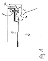
図1はロック装置の1実施例の概略的な断面図。 FIG. 1 is a schematic cross-sectional view of one embodiment of a locking device.
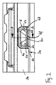
図2は本発明の食器洗い機器のインナドアの端面もしくは側面の1部を凹設部と共に示した平面図。 FIG. 2 is a plan view showing a part of an end surface or a side surface of the inner door of the dishwashing apparatus of the present invention together with a recessed portion.
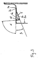
図3は図2のA−A線に沿った断面図。 3 is a cross-sectional view taken along line AA in FIG.
図4は図2に示された凹設部の斜視図。 FIG. 4 is a perspective view of the recessed portion shown in FIG.
図1には本発明による家庭用機器(図示せず)におけるロック装置の1実施例が概略的な断面図で示されている。このロック装置は本発明の食器洗い機器(図示せず)のケーシングドアをそのケーシングにロックするために使用される。図1においては符号1で食器洗い機器の容器のルーフが示されている。この場合、食器洗い機器の内室2には洗おうとする食器が配置される。内室2への接近開口は旋回可能なドア3を介して閉鎖される。このドア3はインナドア3aを有し、このインナドア3aはドア3の内側にて、エンボス加工された金属薄板によって形成されている。容器のルーフの下側には概略的にシール4が示されている。このシール4は接近開口の縁を循環して内室に対して構成され、インナドア3aとケーシング1との間のシールに役立つ。
FIG. 1 shows a schematic sectional view of an embodiment of a locking device in a household appliance (not shown) according to the invention. This locking device is used to lock the casing door of the dishwashing apparatus (not shown) of the present invention to the casing. In FIG. 1, reference numeral 1 indicates a roof of a container of a dishwasher. In this case, the tableware to be washed is arranged in the inner chamber 2 of the dishwasher. The access opening to the inner chamber 2 is closed via a pivotable door 3. The door 3 has an
食器洗い機器の運転中にドアが意図しないのに開放することを回避するためには、食器洗い機器はロック装置を有し、該ロック装置は閉鎖ピンもしくは閉鎖フック5とドアの端面側もしくは上側3bの上の凹設部6とによって形成されている。閉鎖フック5は錠ケーシング内で容器ルーフに統合されかつロック状態でインナドア3aにおける凹設部6に係合する。閉鎖フック5は概略的にしか示されておらず、閉鎖フック5には任意の形状を付与することが可能である。閉鎖フック5は有利にはばね負荷されており、ばね力は閉鎖フックを下へ押圧している。
In order to avoid unintentional opening of the door during operation of the dishwashing appliance, the dishwashing appliance has a locking device which is provided on the closing pin or closing
通常、食器洗い機器に使用されているロック装置では、閉鎖フックはインナドアにて1つの開口の後ろに存在している。前記開口にはドアを閉鎖する場合にケーシングにおける対応する閉鎖プレートが係合し、次いで閉鎖フックが閉鎖プレートにおける孔に落下しかつロックが行なわれる。このためには一方では閉鎖フックのメカニズムのためにドアのブラインドの後ろに場所が必要であり、他方ではインナドアに1つの開口が設けられていなければならない。この結果、食器洗い機器の運転に際し、ドアの内室に水が浸入することがある。これとは異なって本発明のロック装置によれば閉鎖フックはケーシング及び/又はフレーム及び/又は洗い容器に配置され、閉鎖フックは該フックを受容するための凹設部と協働する。したがって一方ではインナドアにおける開口は不要になり、他方ではインナドアに閉鎖フックのための場所を設ける必要はなくなる。したがってドアの内室へ水が浸入することは阻止され、さらにインナドア内に構成空間が提供される。何故ならばいまや錠は閉鎖フックと共にケーシングに存在する構成空間に統合されているからである。インナドアにて空いた構成空間にはいまや、他の構成部分、例えば食器洗い機器の切換え及び制御システムの構成部分のために効果的に利用されることができる。 Normally, in a locking device used in dishwashing equipment, the closing hook is behind one opening at the inner door. The opening engages the corresponding closing plate in the casing when closing the door, and then the closing hook falls into a hole in the closing plate and is locked. This requires on the one hand a place behind the door blind due to the mechanism of the closing hook, and on the other hand an opening in the inner door must be provided. As a result, when the dishwasher is operated, water may enter the interior of the door. In contrast, according to the locking device of the invention, the closing hook is arranged in the casing and / or the frame and / or the washing container, and the closing hook cooperates with a recess for receiving the hook. Thus, on the one hand, no opening in the inner door is necessary, and on the other hand, there is no need to provide a place for a closing hook in the inner door. Accordingly, water is prevented from entering the inner chamber of the door, and a configuration space is provided in the inner door. This is because the lock is now integrated with the closure hook into the component space present in the casing. The interior space vacated by the inner door can now be effectively used for other components, for example, switching of dishwashing equipment and components of the control system.
図2には図1に示されたインナドア3aの端面3bの平面図が示されている。図2からは凹設部6に付与された形状が正確に示されている。凹設部は端面の長手方向で該端面の左側と右側の端部(図示せず)の中央に配置されている。図2からは特に、凹設部がその開口平面にてほぼ長方形であることが判る。この場合、開口平面において角とエッジとには適当な丸みがつけられている。図2に示された凹設部の重要な構想は、凹設部がインナドアに統合された構成部分であることである。つまり凹設部はインナドアに適当な工具でエンボス加工することができる。
FIG. 2 is a plan view of the end face 3b of the
凹設部6は台形の、開口平面に対し比較的に浅く延在する区分6aを有し、該区分6aには右と左とに凹設部の周方向でそれぞれ1つの丸みのつけられた区分6bが接続している。台形の区分6aは凹設部の最深点6cに向かってテーパを成し、丸みのつけられた区分6bはそれぞれ長方形の凹設部の縁の角から斜め下方へ凹設部の最深点6cに向かって延在している。丸みのつけられた区分bの左と右とには2つのほぼ3角形の区分6dが続いている。この区分6dは対応する丸みのつけられた区分6eへ接続している。この区分6eには比較的に急傾斜で下へ向かう区分6fが接続し、この区分6fは緩傾斜の区分6aに向き合っている。急傾斜で下へ向かう区分6fはドアがロック位置にある場合の閉鎖フックのためのストッパとして用いられる。つまり閉鎖フックはドアがロックされた状態でドアを開放しようとすると前記ストッパを押す。
The recessed
図3には図2のA−A線の断面図が示されている。この場合には特に明確に緩傾斜の区分6aと急傾斜の区分6fとの配向が示されている。特に緩傾斜の区分6aが角度βで下方へ開口平面から延びていることが判る。角度βは図3の実施例ではほぼ20度である。しかし、他の任意の角度値も可能である。しかし、角度βは45°よりも小さく、有利には10°と30°との間に位置するようにしたい。同様に図3には第2の区分6fが比較的に急傾斜で、しかも開口平面に対しほぼ垂直に開口平面に対して角度αを成して延びていることが示されている。この角度αは図3の実施例では85°である。しかし他の角度も考えられる。特に角度αは80°と90°との間にあるようにしたい。
FIG. 3 is a sectional view taken along line AA in FIG. In this case, the orientation of the section 6a with a gentle slope and the
図3に示された実施例ではインナドア3aの端面3bには折曲げ部3cが構成されている。さらに図3によっては、凹設部6がインナドアの薄板に統合された構成部分であることが判る。この場合、凹設部は適当なエンボス加工工具で形成される。これによって凹設部の形成は簡易化される。何故ならば凹設部のために特別な構成部分が設けられる必要はなく、この構成部分が付加的な製造ステップで組込まれる必要はないからである。さらにこの場合には凹設部がインナドアに対し適当なシールでシールされる必要もなくなる。
In the embodiment shown in FIG. 3, a bent portion 3c is formed on the end surface 3b of the
図4には図2に示された凹設部がもう一度斜視図で示されている。この図からは緩傾斜の区分6aの台形の形状が良く判る。さらに凹設部の縁に丸みが付けられかつ凹設部において個々の区分が丸みのつけられた区分を介して互いに移行していることが判る。したがってこの凹設部はエッジを有しておらず、ロック装置を操作する場合に損傷を受ける危険は減少させられる。 FIG. 4 is a perspective view once again showing the recessed portion shown in FIG. From this figure, the trapezoidal shape of the gently inclined section 6a can be seen well. It can also be seen that the edges of the recesses are rounded and the individual sections in the recesses are shifted from one another via the rounded sections. Therefore, this recess does not have an edge and the risk of being damaged when operating the locking device is reduced.
1 ケーシングルーフ
2 内室
3 ドア
3a インナドア
3b 表面
3c 折曲げ部
4 シール
5 閉鎖フック
6 凹設部
6a 緩傾斜の区分
6b 丸みのつけられた区分
6c 凹設部の最深部
6d 3角形の区分
6e 丸みのつけられた区分
6f 急傾斜の区分
α,β 角度
DESCRIPTION OF SYMBOLS 1 Casing roof 2 Inner chamber 3
Claims (19)
Applications Claiming Priority (2)
| Application Number | Priority Date | Filing Date | Title |
|---|---|---|---|
| DE102005017871 | 2005-04-19 | ||
| PCT/EP2006/061583 WO2006111504A1 (en) | 2005-04-19 | 2006-04-13 | Household appliance comprising a locking device |
Publications (2)
| Publication Number | Publication Date |
|---|---|
| JP2008537042A true JP2008537042A (en) | 2008-09-11 |
| JP2008537042A5 JP2008537042A5 (en) | 2013-01-17 |
Family
ID=36588873
Family Applications (3)
| Application Number | Title | Priority Date | Filing Date |
|---|---|---|---|
| JP2008507062A Pending JP2008537042A (en) | 2005-04-19 | 2006-04-13 | Household equipment having a locking device |
| JP2008507061A Pending JP2008538397A (en) | 2005-04-19 | 2006-04-13 | Closure member for household equipment |
| JP2008507060A Expired - Fee Related JP4898787B2 (en) | 2005-04-19 | 2006-04-13 | Closure member for household equipment |
Family Applications After (2)
| Application Number | Title | Priority Date | Filing Date |
|---|---|---|---|
| JP2008507061A Pending JP2008538397A (en) | 2005-04-19 | 2006-04-13 | Closure member for household equipment |
| JP2008507060A Expired - Fee Related JP4898787B2 (en) | 2005-04-19 | 2006-04-13 | Closure member for household equipment |
Country Status (14)
| Country | Link |
|---|---|
| US (3) | US8152207B2 (en) |
| EP (3) | EP1874174B1 (en) |
| JP (3) | JP2008537042A (en) |
| KR (3) | KR20080002784A (en) |
| CN (3) | CN101163436B (en) |
| AT (3) | ATE460549T1 (en) |
| AU (3) | AU2006237309B2 (en) |
| BR (3) | BRPI0610849A2 (en) |
| DE (4) | DE102006017961A1 (en) |
| ES (3) | ES2340874T3 (en) |
| NZ (3) | NZ560981A (en) |
| PL (1) | PL1875022T3 (en) |
| RU (3) | RU2401048C2 (en) |
| WO (3) | WO2006111501A1 (en) |
Families Citing this family (38)
| Publication number | Priority date | Publication date | Assignee | Title |
|---|---|---|---|---|
| WO2006111501A1 (en) * | 2005-04-19 | 2006-10-26 | BSH Bosch und Siemens Hausgeräte GmbH | Closing mechanism for a household appliance |
| ES2386266A1 (en) * | 2009-08-25 | 2012-08-14 | BSH Electrodomésticos España S.A. | Dishwasher, in particular household dishwasher |
| WO2011023528A1 (en) * | 2009-08-25 | 2011-03-03 | BSH Bosch und Siemens Hausgeräte GmbH | Dishwasher, in particular domestic dishwasher, having a door lock, and associated door lock |
| US8495836B2 (en) * | 2009-08-27 | 2013-07-30 | Sargent Manufacturing Company | Door hardware drive mechanism with sensor |
| IT1396735B1 (en) * | 2009-11-26 | 2012-12-14 | Bitron Spa | DOOR CLOSING DEVICE FOR THE DOOR OF A HOUSEHOLD APPLIANCE. |
| IT1399631B1 (en) * | 2010-04-21 | 2013-04-26 | Elettrotecnica Rold Srl | "PUSH-PULL" CLOSING DEVICE |
| ES2534291T3 (en) * | 2010-05-14 | 2015-04-21 | Arçelik Anonim Sirketi | A dishwasher comprising an automatic door opening mechanism |
| IT1405177B1 (en) * | 2010-11-26 | 2013-12-20 | Illinois Tool Works | DEVICE FOR LOCKING FOR A HOUSEHOLD APPLIANCE, IN PARTICULAR A DISHWASHER, AND HOUSEHOLD APPLIANCES OF THE SAME |
| DE102011007538A1 (en) * | 2011-03-09 | 2012-09-13 | BSH Bosch und Siemens Hausgeräte GmbH | Locking arrangement for locking a door of a household appliance and household appliance |
| DE102011075554B4 (en) | 2011-05-10 | 2024-03-28 | BSH Hausgeräte GmbH | Household appliance, in particular a dishwasher, with a door locking device |
| KR101794060B1 (en) * | 2011-09-01 | 2017-11-06 | 삼성전자주식회사 | Dish washing machine and basket fixation apparatus |
| CN103015810B (en) * | 2011-09-23 | 2016-02-17 | 伊利诺斯工具制品有限公司 | Door lock and the equipment being provided with identical door lock |
| CN102525371B (en) * | 2012-01-09 | 2015-06-10 | 海尔集团公司 | Door lock device and dish-washing machine with same |
| CA2886056C (en) * | 2012-10-05 | 2020-12-22 | Stanley Security Solutions, Inc. | Anti-friction latchbolt |
| CN104337487B (en) * | 2013-07-31 | 2018-11-09 | 伊利诺斯工具制品有限公司 | Door lock and the dish-washing machine for being equipped with door lock |
| ITTO20130691A1 (en) * | 2013-08-13 | 2015-02-14 | Elbi Int Spa | EQUIPMENT TO CHECK THE CLOSURE OF A DOOR OF A HOUSEHOLD APPLIANCE, IN PARTICULAR FOR A WASHING MACHINE, AS A DISHWASHER MACHINE. |
| CN104287679B (en) * | 2013-12-31 | 2017-05-24 | 宁波方太厨具有限公司 | Water tank type cleaning machine box capable of being locked |
| US10260250B2 (en) | 2014-08-30 | 2019-04-16 | Innovative Building Technologies, Llc | Diaphragm to lateral support coupling in a structure |
| WO2016032537A1 (en) | 2014-08-30 | 2016-03-03 | Innovative Building Technologies, Llc | A prefabricated wall panel for utility installation |
| CN107148540B (en) | 2014-08-30 | 2019-11-26 | 创新建筑科技公司 | The floor used between floors and ceiling panel |
| US9957657B2 (en) * | 2015-01-30 | 2018-05-01 | Emz-Hanauer Gmbh & Co. Kgaa | Appliance lock |
| KR101603593B1 (en) * | 2015-12-24 | 2016-03-15 | (주)청호시스템 | locking device for a door of dish-washer |
| KR102435757B1 (en) * | 2016-01-05 | 2022-08-25 | 엘지전자 주식회사 | Locker and Home Appliance having the same |
| WO2017119677A1 (en) * | 2016-01-05 | 2017-07-13 | Lg Electronics Inc. | Lock and home appliance having the same |
| MX2018010275A (en) | 2016-03-07 | 2019-02-11 | Innovative Building Tech Llc | Waterproofing assemblies and prefabricated wall panels including the same. |
| WO2017156011A1 (en) | 2016-03-07 | 2017-09-14 | Innovative Building Technologies, Llc | Prefabricated demising wall with external conduit engagement features |
| US10961710B2 (en) | 2016-03-07 | 2021-03-30 | Innovative Building Technologies, Llc | Pre-assembled wall panel for utility installation |
| WO2017171215A1 (en) * | 2016-03-28 | 2017-10-05 | Lg Electronics Inc. | Lock and home appliance having the same |
| KR102459278B1 (en) * | 2016-06-20 | 2022-10-26 | 엘지전자 주식회사 | Locker and Home Appliance comprising the same |
| WO2018006790A1 (en) * | 2016-07-06 | 2018-01-11 | 伊利诺斯工具制品有限公司 | Door lock |
| US11098475B2 (en) | 2017-05-12 | 2021-08-24 | Innovative Building Technologies, Llc | Building system with a diaphragm provided by pre-fabricated floor panels |
| US10724228B2 (en) | 2017-05-12 | 2020-07-28 | Innovative Building Technologies, Llc | Building assemblies and methods for constructing a building using pre-assembled floor-ceiling panels and walls |
| US11272826B2 (en) * | 2017-06-23 | 2022-03-15 | Illinois Tool Works Inc. | Appliance door latch system with pre-latching catch alignment system |
| IT201700084013A1 (en) * | 2017-07-24 | 2019-01-24 | Illinois Tool Works | DOOR-LOCK DEVICE FOR HOUSEHOLD APPLIANCES, IN PARTICULAR FOR DISHWASHER |
| CN110512960B (en) * | 2019-09-16 | 2020-09-29 | 温州天健电器有限公司 | Door lock for electric appliance |
| KR102311406B1 (en) * | 2019-11-28 | 2021-10-12 | 에스케이매직 주식회사 | Apparatus for opening and closing door of dish washer |
| US20210238888A1 (en) * | 2020-01-31 | 2021-08-05 | Bitron S.P.A. | Door-lock device and household appliance equipped with such door-lock device |
| CN113530391B (en) * | 2021-07-05 | 2023-05-26 | 佛山市百斯特电器科技有限公司 | Dish washer and automatic mechanism of opening door thereof |
Citations (13)
| Publication number | Priority date | Publication date | Assignee | Title |
|---|---|---|---|---|
| JPS465040Y1 (en) * | 1967-08-11 | 1971-02-22 | ||
| JPS5397500U (en) * | 1977-01-10 | 1978-08-08 | ||
| JPS5535402Y2 (en) * | 1977-05-11 | 1980-08-21 | ||
| JPS5929099Y2 (en) * | 1979-07-04 | 1984-08-21 | 松下電器産業株式会社 | door opening/closing device |
| JPS59192171A (en) * | 1983-04-15 | 1984-10-31 | 株式会社小林製作所 | Catch for furniture |
| JPS6152059U (en) * | 1984-09-07 | 1986-04-08 | ||
| JPH05202663A (en) * | 1992-01-27 | 1993-08-10 | Kubota Corp | Lock part structure between door and door frame |
| JPH0740938U (en) * | 1993-12-27 | 1995-07-21 | 三和シヤッター工業株式会社 | French drop lock drop point installation structure |
| JPH099965A (en) * | 1995-06-30 | 1997-01-14 | Chemo Sero Therapeut Res Inst | Transgenic animal having full-length sequence of hepatitis c viral gene |
| JPH1058974A (en) * | 1996-08-22 | 1998-03-03 | Kasai Kogyo Co Ltd | Door trim for automobile |
| JPH10131589A (en) * | 1996-10-29 | 1998-05-19 | Kimura Shin Kk | Restraint device for folding door, etc. |
| JPH10288369A (en) * | 1997-04-16 | 1998-10-27 | Fuji Kogyo Corp | Range hood fan |
| JPH1142878A (en) * | 1997-07-28 | 1999-02-16 | Takashi Numao | Fitting tool |
Family Cites Families (56)
| Publication number | Priority date | Publication date | Assignee | Title |
|---|---|---|---|---|
| US293424A (en) * | 1884-02-12 | Beommie gopeland and feank weight | ||
| US671792A (en) * | 1901-01-02 | 1901-04-09 | Edwin Frederick Comber | Lock-bolt. |
| US1372000A (en) * | 1919-07-23 | 1921-03-22 | Carl E Anderson | Door-latch |
| US1411059A (en) * | 1921-01-13 | 1922-03-28 | Bassick Co | Latch for doors |
| US1470951A (en) * | 1921-12-14 | 1923-10-16 | Ternstedt Mfg Co | Bolt |
| US1662450A (en) * | 1925-10-08 | 1928-03-13 | Clarence G Anderson | Vehicle door latch |
| US2145112A (en) * | 1937-11-01 | 1939-01-24 | Jr Andrew Fedor | Window lock |
| US3260813A (en) * | 1964-07-01 | 1966-07-12 | Amerock Corp | Door latching and locking device |
| DE1997310U (en) | 1967-05-20 | 1968-11-28 | Zanussi A Spa Industrie | MECHANICAL SAFETY LATCHES, IN PARTICULAR FOR WASHING MACHINES, DISHWASHING MACHINES AND THE LIKE. |
| JPS5029610Y1 (en) * | 1969-12-05 | 1975-09-01 | ||
| DE2106272A1 (en) * | 1971-02-10 | 1972-08-24 | Licentia Gmbh | Electric loading door lock for washing machines and spin dryers |
| JPS5011998U (en) * | 1973-06-05 | 1975-02-06 | ||
| JPS522199U (en) | 1975-06-24 | 1977-01-08 | ||
| US3997201A (en) * | 1975-07-09 | 1976-12-14 | Whirlpool Corporation | Appliance door latch |
| JPS5535402A (en) | 1978-09-01 | 1980-03-12 | Toshiba Corp | Color image pickup tube and manufacturing thereof |
| DE3119764C2 (en) * | 1981-05-18 | 1983-07-21 | Alfred de 2000 Hamburg Waard | Washing machine, especially dishwasher |
| JPS58146680A (en) * | 1982-02-23 | 1983-09-01 | 東京マグネツト応用製品株式会社 | Door contact apparatus |
| JPS5929099A (en) | 1982-08-09 | 1984-02-16 | Hitachi Plant Eng & Constr Co Ltd | Assistant for dehydrating sludge |
| DE3301636A1 (en) * | 1983-01-19 | 1984-07-19 | Bosch-Siemens Hausgeräte GmbH, 7000 Stuttgart | LOCKING DEVICE FOR THE DOOR OF ELECTRICAL HOUSEHOLD APPLIANCES |
| JPS59148753U (en) | 1983-03-22 | 1984-10-04 | 日本電子機器株式会社 | door clamping device |
| JPS6286280A (en) * | 1985-10-11 | 1987-04-20 | 松下電器産業株式会社 | Door opening/closing apparatus |
| US4664433A (en) * | 1986-05-12 | 1987-05-12 | Kwikset Corporation | Latch helical backset adjustment |
| US4776620A (en) * | 1986-09-29 | 1988-10-11 | Whirlpool Corporation | Door latch for dishwasher |
| JPH07116884B2 (en) * | 1987-06-18 | 1995-12-18 | 株式会社ニフコ | Door locking device |
| SU1588418A1 (en) | 1987-07-27 | 1990-08-30 | М.С.Шевчук | Holder for washing, sterilizing and drying vessels |
| SU1565479A1 (en) | 1988-01-08 | 1990-05-23 | Э. П. Овчинников | Vacuum cleaner |
| JPH0544457Y2 (en) * | 1988-05-02 | 1993-11-11 | ||
| SU1760064A1 (en) | 1989-08-17 | 1992-09-07 | Всесоюзный Научно-Исследовательский Институт Вагоностроения | Container door closing device |
| JP2912433B2 (en) * | 1990-09-04 | 1999-06-28 | 株式会社ニフコ | In-vehicle latch device |
| DE9013161U1 (en) * | 1990-09-17 | 1990-11-22 | Paul Hettich GmbH & Co, 4983 Kirchlengern | Device for holding a drawer inserted into a furniture body |
| US5401067A (en) * | 1992-06-10 | 1995-03-28 | Nifco, Inc. | Latch device |
| US5364138A (en) * | 1993-05-10 | 1994-11-15 | Masco Corporation Of Indiana | Door latch assembly with backset adjustment |
| JP3393681B2 (en) | 1993-07-30 | 2003-04-07 | 株式会社フジシール | Flat tube opening device |
| JPH0714061U (en) * | 1993-08-17 | 1995-03-10 | 双葉金属工業株式会社 | Push latch device |
| US5484175A (en) * | 1994-01-28 | 1996-01-16 | Maytag Corporation | Cabinet lock and method for using same |
| US5458382A (en) * | 1994-06-06 | 1995-10-17 | Medeco Security Locks, Inc. | Deadbolt latch assembly |
| JP3338578B2 (en) * | 1995-01-17 | 2002-10-28 | 株式会社ニフコ | Latch device |
| DE19504797C2 (en) * | 1995-02-14 | 1997-04-24 | Ymos Ag Ind Produkte | Locking device for the door of a dishwasher |
| IT238838Y1 (en) * | 1995-02-22 | 2000-11-15 | Dihr Internat | WASHING MACHINE DOOR CLOSING DEVICE |
| JP3680183B2 (en) * | 1995-02-23 | 2005-08-10 | 株式会社ニックス | Door lock |
| JPH10227165A (en) * | 1997-02-14 | 1998-08-25 | Tokyo Magnet Oyo Seihin Kk | Door opening and closing lock device |
| JP3238106B2 (en) * | 1997-08-28 | 2001-12-10 | 株式会社オートネットワーク技術研究所 | In-vehicle display device |
| IT243440Y1 (en) | 1997-11-03 | 2002-03-04 | Gaetano Pagano | LOCKING DEVICE FOR HOUSEHOLD APPLIANCE DOOR, FOR EXAMPLE DISHWASHER |
| JPH11166344A (en) * | 1997-12-05 | 1999-06-22 | Nifco Inc | Latch |
| CN2345649Y (en) * | 1998-06-11 | 1999-10-27 | 海尔集团公司 | Machinery lock switch |
| DE29923492U1 (en) * | 1999-06-25 | 2000-11-23 | Gronbach, Lina, 83549 Eiselfing | hinge |
| JP3814517B2 (en) * | 2001-11-01 | 2006-08-30 | 株式会社ニフコ | Alternate lock device |
| CN1464161A (en) * | 2002-06-11 | 2003-12-31 | 姜方冰 | Drawer cabinet locking apparatus |
| DE10236777A1 (en) * | 2002-08-10 | 2004-03-04 | Ellenberger & Poensgen Gmbh | Electrothermally controlled locking device for an appliance door |
| DE20320530U1 (en) * | 2002-08-10 | 2004-12-16 | Ellenberger & Poensgen Gmbh | Electrically controlled lock, for oven door, has bimetallic drive to release lock if surrounding temperature is lower than set value |
| JP4446809B2 (en) * | 2004-06-18 | 2010-04-07 | 株式会社ニフコ | Lock mechanism |
| JP4477957B2 (en) * | 2004-07-16 | 2010-06-09 | 株式会社ニフコ | Pull-in locking mechanism at the stop position of the opening / closing body |
| US7201411B2 (en) * | 2004-11-18 | 2007-04-10 | Illinois Tool Works Inc | Push latch |
| WO2006111501A1 (en) * | 2005-04-19 | 2006-10-26 | BSH Bosch und Siemens Hausgeräte GmbH | Closing mechanism for a household appliance |
| US7393024B2 (en) * | 2005-11-14 | 2008-07-01 | Illinois Tool Works Inc. | Push latch |
| KR100837907B1 (en) * | 2006-10-18 | 2008-06-13 | 현대자동차주식회사 | Rocking device of tray for automobile |
-
2006
- 2006-04-13 WO PCT/EP2006/061579 patent/WO2006111501A1/en active Application Filing
- 2006-04-13 ES ES06743299T patent/ES2340874T3/en active Active
- 2006-04-13 EP EP20060743297 patent/EP1874174B1/en active Active
- 2006-04-13 BR BRPI0610849-0A patent/BRPI0610849A2/en not_active IP Right Cessation
- 2006-04-13 DE DE200610017961 patent/DE102006017961A1/en not_active Ceased
- 2006-04-13 AT AT06743299T patent/ATE460549T1/en active
- 2006-04-13 KR KR1020077022146A patent/KR20080002784A/en not_active Application Discontinuation
- 2006-04-13 EP EP20060743299 patent/EP1875022B1/en active Active
- 2006-04-13 DE DE200650005586 patent/DE502006005586D1/en active Active
- 2006-04-13 US US11/918,824 patent/US8152207B2/en active Active
- 2006-04-13 WO PCT/EP2006/061580 patent/WO2006111502A1/en active Application Filing
- 2006-04-13 PL PL06743299T patent/PL1875022T3/en unknown
- 2006-04-13 NZ NZ560981A patent/NZ560981A/en unknown
- 2006-04-13 NZ NZ560985A patent/NZ560985A/en not_active IP Right Cessation
- 2006-04-13 DE DE200650006394 patent/DE502006006394D1/en active Active
- 2006-04-13 AU AU2006237309A patent/AU2006237309B2/en active Active
- 2006-04-13 RU RU2007134905A patent/RU2401048C2/en active
- 2006-04-13 EP EP20060743296 patent/EP1874173B1/en active Active
- 2006-04-13 BR BRPI0608358-7A patent/BRPI0608358A2/en not_active IP Right Cessation
- 2006-04-13 DE DE200650005585 patent/DE502006005585D1/en active Active
- 2006-04-13 WO PCT/EP2006/061583 patent/WO2006111504A1/en active Application Filing
- 2006-04-13 US US11/918,823 patent/US8377230B2/en active Active
- 2006-04-13 KR KR1020077022423A patent/KR20080003326A/en not_active Application Discontinuation
- 2006-04-13 BR BRPI0608384 patent/BRPI0608384A2/en not_active IP Right Cessation
- 2006-04-13 AU AU2006237306A patent/AU2006237306B2/en not_active Ceased
- 2006-04-13 JP JP2008507062A patent/JP2008537042A/en active Pending
- 2006-04-13 JP JP2008507061A patent/JP2008538397A/en active Pending
- 2006-04-13 RU RU2007134907A patent/RU2392842C2/en active
- 2006-04-13 AT AT06743296T patent/ATE451050T1/en active
- 2006-04-13 ES ES06743296T patent/ES2334826T3/en active Active
- 2006-04-13 AT AT06743297T patent/ATE451051T1/en active
- 2006-04-13 KR KR1020077021172A patent/KR20080002763A/en not_active Application Discontinuation
- 2006-04-13 RU RU2007134909A patent/RU2376435C2/en not_active IP Right Cessation
- 2006-04-13 JP JP2008507060A patent/JP4898787B2/en not_active Expired - Fee Related
- 2006-04-13 NZ NZ561011A patent/NZ561011A/en unknown
- 2006-04-13 AU AU2006237307A patent/AU2006237307B2/en active Active
- 2006-04-13 ES ES06743297T patent/ES2334827T3/en active Active
- 2006-04-13 CN CN2006800131073A patent/CN101163436B/en active Active
- 2006-04-13 CN CN2006800129923A patent/CN101163844B/en active Active
- 2006-04-13 CN CN2006800131088A patent/CN101163437B/en not_active Expired - Fee Related
-
2007
- 2007-10-16 US US11/873,035 patent/US7775565B2/en not_active Expired - Fee Related
Patent Citations (13)
| Publication number | Priority date | Publication date | Assignee | Title |
|---|---|---|---|---|
| JPS465040Y1 (en) * | 1967-08-11 | 1971-02-22 | ||
| JPS5397500U (en) * | 1977-01-10 | 1978-08-08 | ||
| JPS5535402Y2 (en) * | 1977-05-11 | 1980-08-21 | ||
| JPS5929099Y2 (en) * | 1979-07-04 | 1984-08-21 | 松下電器産業株式会社 | door opening/closing device |
| JPS59192171A (en) * | 1983-04-15 | 1984-10-31 | 株式会社小林製作所 | Catch for furniture |
| JPS6152059U (en) * | 1984-09-07 | 1986-04-08 | ||
| JPH05202663A (en) * | 1992-01-27 | 1993-08-10 | Kubota Corp | Lock part structure between door and door frame |
| JPH0740938U (en) * | 1993-12-27 | 1995-07-21 | 三和シヤッター工業株式会社 | French drop lock drop point installation structure |
| JPH099965A (en) * | 1995-06-30 | 1997-01-14 | Chemo Sero Therapeut Res Inst | Transgenic animal having full-length sequence of hepatitis c viral gene |
| JPH1058974A (en) * | 1996-08-22 | 1998-03-03 | Kasai Kogyo Co Ltd | Door trim for automobile |
| JPH10131589A (en) * | 1996-10-29 | 1998-05-19 | Kimura Shin Kk | Restraint device for folding door, etc. |
| JPH10288369A (en) * | 1997-04-16 | 1998-10-27 | Fuji Kogyo Corp | Range hood fan |
| JPH1142878A (en) * | 1997-07-28 | 1999-02-16 | Takashi Numao | Fitting tool |
Also Published As
Similar Documents
| Publication | Publication Date | Title |
|---|---|---|
| JP2008537042A (en) | Household equipment having a locking device | |
| US6637681B1 (en) | Safety system to prevent the functioning of a blender or food processor if the top of its cup is not in place | |
| JP2008537042A5 (en) | ||
| CN108926239B (en) | Electric pressure cooker and cover opening device thereof | |
| KR102020078B1 (en) | Lock device and apparatus mounted with the same | |
| US20070095836A1 (en) | Pressure cooker | |
| US8151602B2 (en) | Top-loading clothes washing machine with lid enterlock means | |
| KR101779456B1 (en) | A seasoning container cap | |
| KR102139533B1 (en) | Laundry Treating Apparatus | |
| US20100051573A1 (en) | Integrally Molded Hinge Cap | |
| KR20050095008A (en) | Dishwasher | |
| CN216333944U (en) | Safety cover assembly, barrel cover assembly and clothes treatment equipment | |
| KR100736780B1 (en) | Safety device of electric pressure cooker | |
| JP6754189B2 (en) | Beverage container lid lock structure | |
| KR101940244B1 (en) | Laundry treatment machine | |
| KR102329141B1 (en) | Button of electric cooker | |
| KR200202780Y1 (en) | A Preventive Apparatus of Rotation of Electric Cooker Cap | |
| KR102654720B1 (en) | Sliding window handle assembly capable of switching on and off automatic locking | |
| KR20050076520A (en) | Locking device of glove box | |
| KR102281740B1 (en) | Device for locking a lid of laundry treating apparatus | |
| CN207355933U (en) | Cooking utensil | |
| JP2001295459A (en) | Ceiling access door | |
| JPS6315392Y2 (en) | ||
| JP2004041770A (en) | Drum type washing machine | |
| EP2992155B1 (en) | An operating and locking assembly, and a method of providing a condition of use of a window with such an operating and locking assembly |
Legal Events
| Date | Code | Title | Description |
|---|---|---|---|
| A621 | Written request for application examination |
Free format text: JAPANESE INTERMEDIATE CODE: A621 Effective date: 20081218 |
|
| RD04 | Notification of resignation of power of attorney |
Free format text: JAPANESE INTERMEDIATE CODE: A7424 Effective date: 20101228 Free format text: JAPANESE INTERMEDIATE CODE: A7424 Effective date: 20101227 |
|
| A131 | Notification of reasons for refusal |
Free format text: JAPANESE INTERMEDIATE CODE: A131 Effective date: 20110602 |
|
| A601 | Written request for extension of time |
Free format text: JAPANESE INTERMEDIATE CODE: A601 Effective date: 20110804 |
|
| A602 | Written permission of extension of time |
Free format text: JAPANESE INTERMEDIATE CODE: A602 Effective date: 20110811 |
|
| A601 | Written request for extension of time |
Free format text: JAPANESE INTERMEDIATE CODE: A601 Effective date: 20110914 |
|
| A602 | Written permission of extension of time |
Free format text: JAPANESE INTERMEDIATE CODE: A602 Effective date: 20110922 |
|
| A521 | Request for written amendment filed |
Free format text: JAPANESE INTERMEDIATE CODE: A523 Effective date: 20111124 |
|
| A131 | Notification of reasons for refusal |
Free format text: JAPANESE INTERMEDIATE CODE: A131 Effective date: 20120822 |
|
| A524 | Written submission of copy of amendment under article 19 pct |
Free format text: JAPANESE INTERMEDIATE CODE: A524 Effective date: 20121120 |
|
| A02 | Decision of refusal |
Free format text: JAPANESE INTERMEDIATE CODE: A02 Effective date: 20130729 |