JP2008510098A - Acoustic and thermal shielding device - Google Patents
Acoustic and thermal shielding device Download PDFInfo
- Publication number
- JP2008510098A JP2008510098A JP2007526369A JP2007526369A JP2008510098A JP 2008510098 A JP2008510098 A JP 2008510098A JP 2007526369 A JP2007526369 A JP 2007526369A JP 2007526369 A JP2007526369 A JP 2007526369A JP 2008510098 A JP2008510098 A JP 2008510098A
- Authority
- JP
- Japan
- Prior art keywords
- woven fabric
- metal
- sound
- shielding device
- acoustic
- Prior art date
- Legal status (The legal status is an assumption and is not a legal conclusion. Google has not performed a legal analysis and makes no representation as to the accuracy of the status listed.)
- Pending
Links
Images


Classifications
-
- G—PHYSICS
- G10—MUSICAL INSTRUMENTS; ACOUSTICS
- G10K—SOUND-PRODUCING DEVICES; METHODS OR DEVICES FOR PROTECTING AGAINST, OR FOR DAMPING, NOISE OR OTHER ACOUSTIC WAVES IN GENERAL; ACOUSTICS NOT OTHERWISE PROVIDED FOR
- G10K11/00—Methods or devices for transmitting, conducting or directing sound in general; Methods or devices for protecting against, or for damping, noise or other acoustic waves in general
- G10K11/16—Methods or devices for protecting against, or for damping, noise or other acoustic waves in general
- G10K11/162—Selection of materials
-
- B—PERFORMING OPERATIONS; TRANSPORTING
- B60—VEHICLES IN GENERAL
- B60R—VEHICLES, VEHICLE FITTINGS, OR VEHICLE PARTS, NOT OTHERWISE PROVIDED FOR
- B60R13/00—Elements for body-finishing, identifying, or decorating; Arrangements or adaptations for advertising purposes
- B60R13/08—Insulating elements, e.g. for sound insulation
- B60R13/0876—Insulating elements, e.g. for sound insulation for mounting around heat sources, e.g. exhaust pipes
-
- Y—GENERAL TAGGING OF NEW TECHNOLOGICAL DEVELOPMENTS; GENERAL TAGGING OF CROSS-SECTIONAL TECHNOLOGIES SPANNING OVER SEVERAL SECTIONS OF THE IPC; TECHNICAL SUBJECTS COVERED BY FORMER USPC CROSS-REFERENCE ART COLLECTIONS [XRACs] AND DIGESTS
- Y10—TECHNICAL SUBJECTS COVERED BY FORMER USPC
- Y10T—TECHNICAL SUBJECTS COVERED BY FORMER US CLASSIFICATION
- Y10T442/00—Fabric [woven, knitted, or nonwoven textile or cloth, etc.]
- Y10T442/30—Woven fabric [i.e., woven strand or strip material]
- Y10T442/3325—Including a foamed layer or component
Abstract
Description
本発明は、板状要素を備える音響及び熱遮蔽装置に関する。 The present invention relates to an acoustic and heat shielding device comprising a plate-like element.
ドイツ実用新案公報DE91 07 484 U1には熱シールドが開示されている。この熱シールドは排ガスを送る自動車の部品を遮蔽するためのものであり、アルミニウムキャリアシートによって担持される絶縁層を備えている。その絶縁層は規則的に編成されたアルミニウム網と少なくとも1つのアルミニウム箔とからなるインサートを有している。 German utility model publication DE 91 07 484 U1 discloses a heat shield. This heat shield is for shielding automobile parts that send exhaust gas, and includes an insulating layer carried by an aluminum carrier sheet. The insulating layer has an insert consisting of a regularly knitted aluminum mesh and at least one aluminum foil.
また自動車用の他の熱シールドは、ドイツ公開特許公報DE199 39 482 A1でも知られている。この熱シールドは微細穿孔シートメタル成形品として設計されており、熱シールドと隣接する壁との間に断熱効果をもつ空洞(cavity)を有するものである。 Another heat shield for automobiles is also known from German published patent application DE 199 39 482 A1. This heat shield is designed as a finely perforated sheet metal molded product, and has a cavity having a heat insulating effect between the heat shield and the adjacent wall.
ドイツ登録特許公報DE38 21 468 C2には、可撓性絶縁マットと、その絶縁マットによって大部分が覆われるシート状キャリアとを有する絶縁成形品が記載されている。 German Registered Patent Publication DE 38 21 468 C2 describes an insulating molded article having a flexible insulating mat and a sheet-like carrier that is largely covered by the insulating mat.
ドイツ実用新案公報DE81 30 562 U1には、一方が粗目であり他方が細目である2つのアルミニウム管からなるマフラ用の管状編物が記載されている。 German utility model publication DE81 30 562 U1 describes a tubular knitted fabric for a muffler comprising two aluminum tubes, one of which is coarse and the other is fine.
ドイツ公開特許公報DE199 52 689 A1には、複数の接着点によって面積全体にわたって互いに接続される穿孔壁と後壁とを有する遮音壁が開示されている。 German published patent application DE 199 52 689 A1 discloses a sound insulating wall having a perforated wall and a rear wall connected to each other over the entire area by means of a plurality of adhesion points.
さらに音響遮蔽要素については、ヨーロッパ登録特許公報EP1 161 360 B1で知られている。この場合、空間の節約のために規定のサイズ及び規定の配置を有する複数の小さな穿孔を有する板が設けられる。
Furthermore, acoustic shielding elements are known from European Registered Patent Publication
ドイツ公開特許公報DE30 29 610 A1には、繊維及び/又は糸に金属被覆が施された3次元シート状繊維構造からなる吸音要素が記載されている。さらに、起毛織物又は起毛編物を金属被覆するそのような吸音要素の製造方法についても記載されている。 German published patent publication DE 30 29 610 A1 describes a sound-absorbing element comprising a three-dimensional sheet-like fiber structure in which the fibers and / or yarns are coated with a metal. Furthermore, a method for producing such a sound-absorbing element for metallizing a raised fabric or a raised knitted fabric is also described.
しかしながら、既に知られている公知の解決手段はいずれも比較的特殊であり、特に防熱作用か防音作用のいずれかしか達成することができない。また既に知られている技術要素は、大抵の場合、製造が非常に複雑であるという欠点もある。 However, all of the known solutions that are already known are relatively specific, and in particular can only achieve either a heat or sound insulation effect. The already known technical elements also have the disadvantage that they are usually very complicated to manufacture.
優先日のないDE103 45 575.2−53には、板状要素を備える音響及び熱遮蔽装置が記載されている。この板状要素は、接点が焼結によって互いに接続される経糸及び緯糸を有する少なくとも1層の金属織布を有する。しかしながらこの解決手段は、音響及び熱遮蔽装置の製造費用が比較的高額になってしまうという欠点がある。 DE 103 45 575.2-53, with no priority date, describes an acoustic and heat shielding device with plate-like elements. The plate-like element has at least one layer of metal woven fabric with warps and wefts whose contacts are connected to each other by sintering. However, this solution has the disadvantage that the production costs of the acoustic and heat shielding device are relatively high.
したがって、本発明の目的は、単純で且つ特に費用対効果の良い手段によって製造することができるとともに、熱作用及び音響作用に関して部品を遮蔽するために柔軟な方法で用いることができる、音響及び熱遮蔽装置を提供することにある。 The object of the present invention is therefore the acoustic and thermal which can be produced by simple and particularly cost-effective means and can be used in a flexible way to shield parts with respect to thermal and acoustic effects. It is to provide a shielding device.
本発明によれば、この目的は、板状要素が、経糸及び緯糸を有する少なくとも1層の金属又は合成織布を有し、金属又は合成織布が複数の細孔を有することで果たされる。 According to the invention, this object is achieved in that the plate-like element has at least one layer of metal or synthetic woven fabric with warp and weft and the metal or synthetic woven fabric has a plurality of pores.
本発明者らは、驚くべきことに、本発明による音響及び熱遮蔽装置の板状要素がほとんどの用途で、経糸と緯糸との接点を焼結するという非常に費用集約的なステップを省いた場合でも、特に布が自然に解けないようにするのに十分な強度を有することを見出した。これにより、装置全体をはるかに費用効果的に製造できるため、市販の可能性が大幅に高くなる。 The inventors have surprisingly eliminated the very cost-intensive step of sintering the warp and weft contacts in most applications, where the plate-like element of the acoustic and heat shield device according to the invention is used. Even in this case, it has been found that the fabric has sufficient strength to prevent it from unwinding naturally. This greatly increases the commercial potential as the entire device can be manufactured much more cost-effectively.
本発明によれば、板状要素は、複数の細孔(隙間)が設けられた金属又は合成織布を有し、その細孔はその中に空気が存在することによって断熱材としての役割を果たすため、熱遮蔽性を実現することができる。したがって断熱は、空気又はガスで満たされた金属又は合成織布の中の細孔によってもたらされる。この場合、その織布にある細孔の数が多い、すなわち開孔率が高いほど、織布の断熱性は高くなる。ワイヤ直径が小さく、織布の層が多いほど、得られる断熱性も高くなる。織布の密度も、断熱に影響を及ぼすものであり、その密度が低いほど断熱性は高くなる。さらに、織布の断熱性の程度は、熱伝導率の低い材料を経糸及び緯糸に用いることによって高めることができる。 According to the present invention, the plate-like element has a metal or synthetic woven fabric provided with a plurality of pores (gap), and the pores serve as heat insulating materials due to the presence of air therein. Therefore, heat shielding properties can be realized. Thermal insulation is thus provided by pores in the metal or synthetic fabric filled with air or gas. In this case, the more the number of pores in the woven fabric, that is, the higher the hole area ratio, the higher the heat insulating property of the woven fabric. The smaller the wire diameter and the more layers of woven fabric, the higher the thermal insulation obtained. The density of the woven fabric also affects the heat insulation. The lower the density, the higher the heat insulation. Furthermore, the degree of thermal insulation of the woven fabric can be enhanced by using a material having low thermal conductivity for warp and weft.
さらに、前記織布に形成される多数の細孔は、これらの細孔に入る音を確実に吸収するため、音の音速エネルギーが熱エネルギーに変換されて音が減衰される。したがって、本発明による音響及び熱遮蔽装置は、音響的に有効な吸収材を形成する。この場合、織布がもつ音の伝達抵抗は吸音の関数であり、伝達抵抗が大きいほど優れた吸音効果をもたらす。熱伝導率に優れた織布が用いられる場合、熱エネルギーは、音波の圧力振幅内で急速に散逸し、したがって吸収される。細孔の大きさ、すなわち緯糸及び/又は経糸の間隔を小さくすると、吸音性を高めることが可能になる。この場合、音波は、織布の中で伝達経路が偏向されることによって抵抗を受け、この抵抗が吸音効果をもたらす。織布に入り込まないような音波は、経糸及び/又は緯糸によって拡散反射されることとなる。 Further, since the large number of pores formed in the woven fabric reliably absorb sound entering these pores, the sound velocity energy of the sound is converted into thermal energy and the sound is attenuated. Thus, the acoustic and thermal shielding device according to the invention forms an acoustically effective absorber. In this case, the sound transmission resistance of the woven fabric is a function of sound absorption, and the greater the transmission resistance, the better the sound absorption effect. If a woven fabric with good thermal conductivity is used, the thermal energy is quickly dissipated and thus absorbed within the pressure amplitude of the acoustic wave. If the size of the pores, that is, the interval between the weft and / or the warp, is reduced, it is possible to increase the sound absorption. In this case, the sound wave receives resistance by deflecting the transmission path in the woven fabric, and this resistance provides a sound absorbing effect. Sound waves that do not enter the woven fabric are diffusely reflected by the warp and / or the weft.
この場合、要求特性に応じて、断熱と吸音との間で妥協案を探さなければならない。 In this case, a compromise must be sought between insulation and sound absorption depending on the required properties.
板状要素に織布を用いることの特別な利点は、この場合、例えば編物製品の場合よりもはるかに単純且つ迅速に製造できることである。非常に細いワイヤを織布に用いることができるため、極めて薄く、したがってそれに対応して柔軟な板状要素を形成することができるという点で、さらなる利点が生まれる。この柔軟性は、本発明による音響及び熱遮蔽装置を、特に自動車のエンジン空間にある特定の熱及び/又は音波放射部品に適合させる場合に有利である。 A special advantage of using a woven fabric for the plate-like elements is that in this case it can be produced much simpler and faster than for example for knitted products. Since very thin wires can be used for the woven fabric, a further advantage arises in that very thin and therefore correspondingly flexible plate-like elements can be formed. This flexibility is advantageous when the acoustic and heat shielding device according to the invention is adapted to specific heat and / or sound radiating components, especially in the engine space of a motor vehicle.
本発明による音響及び熱遮蔽装置は、当然ながら、音響遮蔽のみ又は熱遮蔽のみが必要である場合にも用いることができる。 The acoustic and thermal shielding device according to the invention can of course also be used when only acoustic shielding or only thermal shielding is required.
本発明の非常に有利な改良点では、圧力を加えることによって金属又は合成織布の厚さを薄くする措置を取ることができる。このように金属又は合成織布の厚さを薄くすると、金属又は合成織布の開孔率が影響を受けることになり、厚さが薄い場合ほどそれに対応して得られる開孔率を低くすることができる。その結果さらに、本発明による音響及び熱遮蔽装置の音響抵抗に影響を及ぼすことができるため、本発明による装置を様々な周波数に適合させることができる。さらに、金属又は合成織布の厚さの変化によって、経糸と緯糸との接触面積を拡大することができるため、金属又は合成織布の熱伝導率にも影響を及ぼすことができる。さらに、圧力を加えることによって、織布の中の音の伝達抵抗も設定することができる。 In a very advantageous refinement of the invention, measures can be taken to reduce the thickness of the metal or synthetic fabric by applying pressure. When the thickness of the metal or synthetic woven fabric is reduced in this way, the aperture ratio of the metal or synthetic woven fabric is affected, and the thinner the thickness, the lower the corresponding aperture ratio. be able to. As a result, the acoustic resistance of the acoustic and thermal shielding device according to the invention can be further influenced, so that the device according to the invention can be adapted to different frequencies. Furthermore, since the contact area between the warp and the weft can be increased by changing the thickness of the metal or synthetic woven fabric, the thermal conductivity of the metal or synthetic woven fabric can be affected. Furthermore, the transmission resistance of sound in the woven fabric can be set by applying pressure.
好ましい一実施形態では経糸及び/又は緯糸が電気化学的な処理又はラッカー塗りされる。この場合には、本発明による装置の防食性を高めることができる。 In a preferred embodiment, the warp and / or weft are electrochemically treated or lacquered. In this case, the corrosion resistance of the device according to the present invention can be improved.
代替的に、金属又は合成織布を電気化学的な処理又はラッカー塗工する措置を取ることもできる。 Alternatively, measures can be taken to electrochemically treat or lacquer metal or synthetic fabrics.
さらに、金属又は合成織布の電気化学的な処理又はラッカー塗工によって、経糸と緯糸との接点がさらに補強されるため、金属又は合成織布の強度をさらに高めることができる。 Furthermore, since the contact between the warp and the weft is further reinforced by electrochemical treatment or lacquer coating of the metal or synthetic woven fabric, the strength of the metal or synthetic woven fabric can be further increased.
本発明による装置の様々な好ましい使用は、独立請求項8〜11から明らかとなるであろう。 Various preferred uses of the device according to the invention will become apparent from the independent claims 8-11.
本発明の目的を達成するための製造方法は、請求項12の特徴から明らかとなるであろう。請求項12に記載の製造方法によって、金属又は合成織布を有する板状要素を備える本発明による装置を、簡単に製造することができる。 The manufacturing method for achieving the object of the present invention will be apparent from the features of claim 12. By the manufacturing method according to claim 12, the device according to the present invention comprising a plate-like element having a metal or synthetic woven fabric can be easily manufactured.
圧力を加えることによって金属又は合成織布の厚さを薄くすることが特に好ましく、この場合、さらにこれに関して、加圧力を圧延によって金属又は合成織布に加える措置を取ることができる。 It is particularly preferred to reduce the thickness of the metal or synthetic fabric by applying pressure, in which case further measures can be taken in this regard to apply the applied pressure to the metal or synthetic fabric by rolling.
金属又は合成織布の圧延には、織布が相互に機械的に接合される、特に緯糸が経糸に押し込まれて経糸も緯糸に押し込まれることで非常に優れた織布の絡み合いが得られ、織布が大幅に改善された結合及び高い強度を得ることができる、上述されていない大きな利点がある。これは特に、本発明による装置が製織後に比較的高い造形度で造形される場合に重要である。さらに、圧延によって織布に張力が生じ、その結果、織布の固有周波数を設定することができる。 For rolling metal or synthetic woven fabrics, the woven fabrics are mechanically joined to each other, in particular, the weft is pushed into the warp and the warp is also pushed into the weft, so that a very good entanglement of the woven fabric is obtained, There are significant advantages not mentioned above that the woven fabric can obtain a greatly improved bond and high strength. This is particularly important when the device according to the invention is shaped with a relatively high degree of shaping after weaving. Furthermore, tension is generated in the woven fabric by rolling, and as a result, the natural frequency of the woven fabric can be set.
本発明のさらなる好ましい一実施形態において、少なくとも1つの構造化されたローラが金属又は合成織布の圧延に用いられる場合、凸凹状、突起状、又は波状の表面をもつ金属又は合成織布を得ることができ、これによって吸音及び音波反射に影響を及ぼすことができる。 In a further preferred embodiment of the invention, when at least one structured roller is used for rolling metal or synthetic woven fabric, a metal or synthetic woven fabric having an uneven, protruding or wavy surface is obtained. Which can affect sound absorption and sound wave reflection.
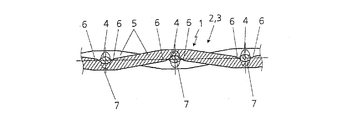
図1は、1層の金属又は合成織布3を有するか、又は本質的に金属又は合成織布3から成る板状要素2を備える音響及び熱遮蔽装置1の上面図を示す。金属又は合成織布3に加えて、板状要素2は、図示は省略するがさらなる他の層を有していてもよい。金属又は合成織布3は、経糸4及び経糸4に対してほぼ垂直に延びる緯糸5を有する。さらに金属又は合成織布3は、経糸4と緯糸5との間に位置しており図2に示す図中で見ることができる細孔6を有する。金属又は合成織布3の細孔6は、板状要素2に衝突する音の音速エネルギーを熱に変換することによって音波を吸収する役割を果たす。
FIG. 1 shows a top view of an acoustic and
特定の要求特性を満たすために、経糸4及び緯糸5として異形ワイヤを用いてもよい。この場合、その異形ワイヤには種々の外形のものを適宜用いることができる。
In order to satisfy specific required characteristics, deformed wires may be used as the
音響及び熱遮蔽装置1は、例えば、内燃機関のエンジン空間で任意のタイプの音波放射部品の音響遮蔽に用いることができる。装置1はさらに、マフラ及び排気系の内部、エンジンカバー用のキャリア材料として、減衰シール用のキャリア材料として、付加的な減衰の有無を問わずヘルムホルツ共鳴器用の金属シーティングとして、箔カバーを有するヘルムホルツ共鳴器として、ヘルムホルツ共鳴器のカバーとして、弾性抵抗フィルムとして、ベーキングオーブン、トースター、又は他の家庭用電化製品用の断熱材として、洗濯機及び他の家庭用電化製品の駆動モータ用の音響遮蔽として、例えば冷蔵庫キャビネットの圧縮機用の吸音材料として、タービン、自動車エンジン、暖房システム、圧縮機等の流れダクト及び吸気ダクトのライニングとして、マフラのライニングとして、マフラの中間壁又は内管として、防音ブース、音響壁、又は音響カプセルのカバー層として、任意のタイプの駆動モータ用の音響遮蔽として、吸音ハウジングとして、又は板状及び膜状吸収材として用いられる可能性がある。遮蔽すべき又は板状要素2から製造すべき最大限に多様な形状の部品に板状要素2を適合させるために、板状要素2は、穿孔シートとして、スロット付きシートとして、又はエキスパンドメタルとして設計することが可能である。さらに、板状要素2は、成形によって、例えば深絞りによって、遮蔽すべき部品に適合した形状にすることができる。板状要素2は、自立形部品に成形することができ、これをビード及びフランジによって補強することが可能である。さらに、板状要素2は、深絞り、エンボス加工、及び/又はスタンピングによって、フード、シェル、ポット、ファンネル、及び同様の部品に造形することができる。例えばハット形、ボックス形、又は角形等の外形を、板状要素2から形成することができる。さらに、円形、楕円形、矩形、三角形、又は任意の他の断面を有する管状の外形を、板状要素から製造することができる。板状要素は、折り曲げてもよく、凹凸を付けてもよく、穿孔してもよく、又はリム穴を設けてもよい。同じ板状要素2、さらには異なる板状要素2の複数の層が用いられる場合、異なる織布密度及び組み合わせを有する多層フード又はシェルをこれらから製造することができる。板状要素2は、例えばセラミックフリース、バサルトウール、オーガニックウール、シートメタル箔、又は厚手金属シート等、他の吸音媒体でコーティング又は被覆してもよい。さらに、吸音に関してより優れた効果を得るために、板状要素2又はそれから製造される部品を、微細穿孔箔、穿孔シート、又はエキスパンドメタルと組み合わせてもよい。音響エネルギーを弱めるために、板状要素2又はこれから製造される部品を音波放射によって励振させることで、音響エネルギーを弱める措置も取ることができる。
The acoustic and
音の吸収に加えて、音響及び熱遮蔽装置1は、特に同じく、例えばマフラ、排気ライン、ターボチャージャ、触媒コンバータ、又は他の熱放射部品等の内燃機関の部品上で、又はこれらの部品とともに用いられる、熱遮蔽としての役割も果たす。この目的のために、経糸4と緯糸5との間の細孔6は、必要な断熱性を確保する空気クッションを形成する。板状要素2の熱伝導率は、経糸4と緯糸5とが各接点7で接触することによって生じ、これらの接点7が大きいほど熱伝導率が大きくなる。さらに、板状要素2は、金属又は合成織布3として設計されることによって、大きな冷却表面を有するため、板状要素2に対して作用する熱を急速に散逸させることができる。
In addition to sound absorption, the sound and
金属又は合成織布3を製造するために、経糸4及び緯糸5は、例えば平織り(smooth braid、glatten Tresse)又は綾織り(twill weave、Koeperbindung)を製造する製織方法等、それ自体が既知の製織方法によって織り合わせられ、この場合、ほぼ全ての既知の製織方法を用いることができることを強調すべきである。特定のタイプの製織によって、異なる構造、例えば滑らかな構造及び粗い構造を織布の両面に得ることができる。金属又は合成織布3の表面粗さによって吸音に影響を及ぼすことができ、表面が粗いほど、音波が大きく偏向されるため優れた吸音性を得ることができる。さらに考えられる織布のタイプは、平織り(plain weave、glatte Bindung)、杉綾織り(zigzag and alternating twill、Spitz- und Weckselkoeper)、五枚綾織り(five-shaft twill、Fuenfshaftkoeper)、綾畳織り(twill braid、Koepertresse)、複式綾畳織り(duplex、Duplex)、逆平畳織り(armor braid、Panzertresse)、粗目綾織り(broad-mesh twill braid、Breitmaschenkoepertresse)、又は金属繊維フリースを有する布(fabric with metal fiber fleece、Gewebe mit Metallfaservlies)であり、細孔6のサイズには織布のタイプの選択によって影響を及ぼすことができる。さらに、経糸4及び/又は緯糸5には、製織前にリン酸亜鉛又はリン酸マンガン層を設けることもできる。織布3の表面粗さは、リン酸塩処理によって、又はセラミック又は炭素、プラスチック、若しくは金属粉末から成る粉末でのコーティングによって生成することができる。
In order to produce the metal or synthetic woven fabric 3, the
経糸4及び緯糸5の材料は、例えば、鋼材料、銅材料、又はアルミニウム材料を用いることができる。さらに考えられる経糸4及び緯糸5の材料は、原則として、全ての貴金属、重金属、及び軽金属であり、特にばね鋼、高級鋼、及び軽金属合金でもある。さらに、プラスチックを経糸4及び/又は緯糸5に用いることもできる。好ましくは、経糸4及び緯糸5は同じ材料から成るが、異なる材料を用いてもよく、すなわち、プラスチックと金属との組み合わせも使用材料として可能である。
As the material of the
アルミニウム材料が経糸4及び緯糸5に用いられる場合、これにより、非常に軽量の板状要素2ができ、優れた熱伝導率及び優れた成形性も与えられる。厳密にはアルミニウム材料に関する限り、織布3の強度及び結合力は、好ましくはカレンダローラ等の圧延により織布3の厚さを薄くすることによって、大幅に高めることができることが分かっている。
When an aluminum material is used for the
例示的な本実施形態では、経糸4及び緯糸5はほぼ同じ直径を有し、すなわち、最大差は0.01〜0.5mmとなる。当然ながら、経糸4及び緯糸5は、大幅に異なる直径を有することもできる。しかしながら、原則として、あらゆるワイヤの太さが可能である。
In this exemplary embodiment, the
経糸4を緯糸5と接点7でよりしっかりと結合させるために、織布3は、製造後又は成形後に電気化学的に処理することができる。このように、例えば、比較的単純であり、したがって費用効果的な鋼材料からなる織布3には、亜鉛めっき、ニッケルめっき、銅めっき、アルミめっき、又は別の適当な材料での電気化学的被覆を施すことができる。これにより、経糸4及び緯糸5にあまり高価ではない材料が用いられ、続いてこれに電気化学的コーティングが設けられるという点で、費用を節約することができる。さらに、織布3のさらなる補強がこのようにして得られる。代替的に、電気化学的に処理又はラッカー塗工した経糸4及び緯糸5も、織布3の製造に用いることができる。この場合、織布3の防食が最も重要であり、当然ながら、これも織布3の全体を電気化学的にコーティングすることによって得られる。
In order to bond the
電気化学的処理の代替法は、金属又は合成織布3のラッカー塗工であり、これは特に、音響及び熱遮蔽装置1が熱応力を受けない場合に用いることができる。好ましくは、この目的のために、金属又は合成織布3をラッカー浴に浸漬させる。この場合、ラッカーは特に接点7に塗布されて、毛管作用によって細孔6の隅に引き込まれるため、これらの細孔6のサイズは小さくなる。このように、細孔6のサイズが小さくなることで、さらに金属又は合成織布3による吸音が影響を受けるだけでなく、金属又は合成織布3の全体の剛性も、接点7の領域の結合力が高まることによって得られる。
An alternative to electrochemical treatment is the lacquering of metal or synthetic woven fabric 3, which can be used in particular when the acoustic and
上述のように、板状要素2が造形される場合、電気化学的コーティング又はラッカー層への損傷を防止するために、造形後に電気化学的処理又はラッカー塗工を行うのが得策である。 As mentioned above, when the plate-like element 2 is shaped, it is advantageous to perform an electrochemical treatment or lacquering after shaping in order to prevent damage to the electrochemical coating or lacquer layer.
図4〜図6は、製織後に圧延された金属又は合成織布3を有する板状要素2を備える本発明による音響及び熱遮蔽装置1の一実施形態を示す。図4に示す上面図において、この圧延の結果として、経糸4と緯糸5との間の接点7が非常に平坦化されているため、全体として金属又は合成織布3の厚さの減少が得られることが分かる。代替的に、鍛造型内で金属又は合成織布3を加圧することによって、加圧力を加えることもできる。さらに、加圧力を加えることによって金属又は合成織布3を圧接することが可能である。例えば、圧延の結果として、圧延前の厚さが約1.4mmであった織布3を約0.4mmの厚さにすることができる。
4 to 6 show an embodiment of an acoustic and
織布3を適当な厚さに圧延又は加圧した後、織布3にリン酸塩処理、ラッカー塗工、又は電気化学的若しくは溶融浴内でのコーティングを施してもよく、又はセラミック層若しくは炭素繊維を織布3に施してもよい。織布3の処理にさらに考えられるのは、適当な厚さに圧延又は加圧した後に、例えば織布3自体と同じ材料からなる金属繊維又は粉末を噴霧又は焼結させることである。 After rolling or pressing the woven fabric 3 to an appropriate thickness, the woven fabric 3 may be subjected to phosphating, lacquering, or coating in an electrochemical or molten bath, or a ceramic layer or Carbon fiber may be applied to the woven fabric 3. Further conceivable for the treatment of the woven fabric 3 is to spray or sinter metal fibers or powder made of, for example, the same material as the woven fabric 3 itself after rolling or pressing to an appropriate thickness.
図5に示す断面から、経糸4と緯糸5との間の細孔6が、図1〜図3に示す実施形態よりもはるかに小さな断面を有することで、金属又は合成織布3による吸音の変化につながることが明らかとなるであろう。したがって、圧延時の成形の程度に応じて、金属又は合成織布3の音響抵抗を設定することができる。
From the cross section shown in FIG. 5, the
図6を図3と比較すると、緯糸5が圧延によって経糸4の両側に食い込んでおり、経糸4及び緯糸5の両方が変形していることが明らかとなる。この機械的接合操作の結果として、経糸4と緯糸5との絡み合いが大幅に改善され、したがって金属又は合成織布3の強度又は剛性の大幅な向上が得られることが明らかである。織布の圧延又は加圧の結果として、織布3の垂直方向及び水平方向の圧縮が生じる。しかしながら、圧延状態でも、経糸4と緯糸5との間でかなり小さいとはいえある程度の動きが依然として可能であるため、音響エネルギーを弱めることができる。織布3の圧延又は加圧は、ある程度の開孔率を常に保ったまま板状要素2がシート状の特徴を得るように行われる。圧縮された織布3は、非常に容易に切断、スタンピング、圧着、及び深絞りを施すことができ、最大で1.8の深絞り比を得ることができる。さらに、織布3は、例えばスポット溶接及びロールシーム溶接等の様々な溶接法、並びに全ての溶融溶接法によってさらに加工することができる。織布3の圧延又は加圧のさらなる利点は、圧延又は加圧によって圧縮が生じるため、適当なサイズのブランクに切断する場合に外側のワイヤ又は糸が解けにくいことであることが分かる。代替的に、織布3の圧延又は加圧は省いてもよい。
Comparing FIG. 6 with FIG. 3, it becomes clear that the
金属又は合成織布3の表面の構造化を達成するために、金属又は合成織布3の圧延に用いられる一方の、さらには両方のローラが、金属又は合成織布3に形成される粗面を有し得る。その結果、金属又は合成織布3に衝突する音の分散を変えることができる。製織前に、吸音性を高めるために、経糸4及び緯糸5の両方を半径方向及び/又は軸方向に粗面化することができる。織布3が適当なサイズに切断される場合、適当なサイズに切断されたブランクの縁を圧着することによってこれらの縁を補強することができ、その結果として、損傷の危険性を減らすことができる。代替的又は付加的に、例えばレーザビームを用いて切断部を切り離すことによって、適当なサイズに切断されたブランクの縁を融着させることも可能である。
In order to achieve the structuring of the surface of the metal or synthetic woven fabric 3, one or both of the rollers used for rolling the metal or synthetic woven fabric 3 are rough surfaces formed on the metal or synthetic woven fabric 3. Can have. As a result, the dispersion of the sound impinging on the metal or synthetic woven fabric 3 can be changed. Before weaving, both the
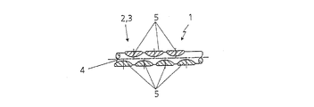
織布3の剛性は、経糸4の数及び直径によって変化する。原則として、例えば円形、角形、楕円形等の全てのワイヤ形態が経糸4及び緯糸5に可能であるが、全く同じ織布3で異なるワイヤ形態を用いることもできる。図2において、細孔6が経糸4の両側で最大になっていることがさらに分かる。緯糸5から分かるように、最大の貫通孔6は、上側の緯糸5と下側の緯糸5との間に位置しており、これは同様に図2から明らかとなるであろう。したがって、図2に示される2本の緯糸5と経糸4との間には、三角形の空間が形成され、これが本特許出願では細孔6と呼ばれるものであり、特に、平織り、綾畳織り、複式綾畳織り、ベータメッシュ、及びロバスターなどのタイプの織布で特に吸音性があることが分かっている。音波が経糸4の細孔6に沿って偏向されることによって、ヘルムホルツ効果が生じ、これによって音波が吸収される。この場合、織布3の変形が大きいほど細孔6は細くなる。
The rigidity of the woven fabric 3 varies depending on the number and diameter of the
複数の織布層が用いられる場合、これらは相互いに緩く重なっていてもよく、相互いに密着していてもよい。この密着は、例えば、溶接、ねじ留め、リベット留め等によって行うことができ、個々の層を共通のフレームに入れることができる。図7は、上述のように圧延又は加圧された織布3の緯糸5を分解状態で示しており、その変形を明確に見ることができる。図8は、圧延された織布3の経糸を分解状態で示している。ここでも同様に、変形を明確に見ることができる。
When a plurality of woven fabric layers are used, these layers may overlap each other loosely or may adhere to each other. This close contact can be achieved, for example, by welding, screwing, riveting, etc., and the individual layers can be placed in a common frame. FIG. 7 shows the
約50%の開孔率を有する圧延されていない織布3での音の通過を、約25%の開孔率を有する圧延された織布3での音の通過と比較できるように、両方の状態の音の通過を図9及び図10においてそれぞれの矢印で示す。この場合、圧延されていない織布3よりも圧延された織布3の方が音が広く分配されることが分かる。 Both so that the passage of sound in a non-rolled woven fabric 3 having a porosity of about 50% can be compared with the passage of sound in a rolled woven fabric 3 having a porosity of about 25%. The passage of sound in this state is indicated by arrows in FIGS. 9 and 10. In this case, it can be seen that the rolled fabric 3 is more widely distributed than the unrolled fabric 3.
図3と同様の図において、図11は、例として垂直方向に貫通する細孔6aを示している。それに対して、図12は、音を最大限に吸収する、経糸ワイヤ又は水平方向の細孔6b及び楔形孔空間6cを示している。
In the same figure as FIG. 3, FIG. 11 shows the pore 6a penetrating in the vertical direction as an example. In contrast, FIG. 12 shows a warp wire or
すでに上述したように、最大限に多様な工作物を板状要素2又は音響及び熱遮蔽装置1から製造することができる。装置1から形成されるこのような工作物の一例、正確には排気マニホルドの遮蔽シートを図13に示す。この遮蔽シートは、固体伝播音の伝達を回避するために、排気マニホルドから特定の距離の場所に、好ましくは排気マニホルドに接続されない部品に取り付けられる。
As already mentioned above, a wide variety of workpieces can be produced from the plate-like element 2 or the acoustic and
Claims (20)
前記板状要素(2)は経糸(4)及び緯糸(5)を有する少なくとも1層の金属又は合成織布(3)を有し、前記金属又は合成織布(3)は複数の細孔(6)を有し、前記経糸(4)と前記緯糸(5)とが接点(7)において共に焼結されないことを特徴とする、板状要素を有する音響及び熱遮蔽装置。 An acoustic and heat shielding device having a plate-like element,
The plate-like element (2) has at least one layer of metal or synthetic woven fabric (3) having warp (4) and weft (5), and the metal or synthetic woven fabric (3) has a plurality of pores ( 6) A sound and heat shielding device having a plate-like element, characterized in that the warp (4) and the weft (5) are not sintered together at the contact (7).
金属材料からなる前記経糸(4)と前記緯糸(5)とを織り合わせて複数の細孔(6)を有する金属又は合成織布(3)を製造し、前記経糸(4)と前記緯糸(5)とが接点(7)において共に焼結されないことを特徴とする音響及び熱遮蔽装置の製造方法。 A method for producing a sound and heat shield device, comprising:
A metal or synthetic woven fabric (3) having a plurality of pores (6) is produced by weaving the warp (4) and the weft (5) made of a metal material, and the warp (4) and the weft ( And 5) are not sintered together at the contacts (7).
Applications Claiming Priority (2)
| Application Number | Priority Date | Filing Date | Title |
|---|---|---|---|
| DE102004039706A DE102004039706B3 (en) | 2004-08-17 | 2004-08-17 | Apparatus for acoustic and thermal shielding, use and manufacturing method |
| PCT/EP2005/008831 WO2006018258A2 (en) | 2004-08-17 | 2005-08-13 | Acoustic and thermal shielding device |
Publications (1)
| Publication Number | Publication Date |
|---|---|
| JP2008510098A true JP2008510098A (en) | 2008-04-03 |
Family
ID=35433408
Family Applications (1)
| Application Number | Title | Priority Date | Filing Date |
|---|---|---|---|
| JP2007526369A Pending JP2008510098A (en) | 2004-08-17 | 2005-08-13 | Acoustic and thermal shielding device |
Country Status (9)
| Country | Link |
|---|---|
| US (1) | US20080096451A1 (en) |
| EP (1) | EP1784815B1 (en) |
| JP (1) | JP2008510098A (en) |
| CN (1) | CN101040319A (en) |
| AT (1) | ATE528745T1 (en) |
| BR (1) | BRPI0514507A (en) |
| DE (1) | DE102004039706B3 (en) |
| MX (1) | MX2007001983A (en) |
| WO (1) | WO2006018258A2 (en) |
Cited By (1)
| Publication number | Priority date | Publication date | Assignee | Title |
|---|---|---|---|---|
| JP2014526713A (en) * | 2011-09-08 | 2014-10-06 | ヘクセル コーポレイション | Separation of diaphragm in sound-absorbing beehive |
Families Citing this family (21)
| Publication number | Priority date | Publication date | Assignee | Title |
|---|---|---|---|---|
| DE102007058895A1 (en) | 2007-12-05 | 2009-06-10 | Poroson Gmbh | Acoustic heat shield for internal combustion engine of motor vehicle, has insert arranged in intermediate area, and carrier plate consists of element comprising layer made from fabrics, where insert comprises layer made from break foil |
| DE102008022652A1 (en) | 2008-05-07 | 2009-11-12 | Poroson Gmbh | Heat and sound insulating covering element i.e. underbody cover, for e.g. shielding engine of motor vehicle, has plate shape element's flat section arranged between anchoring element and supporting element with distance to component |
| DE102008056031A1 (en) * | 2008-11-05 | 2010-05-06 | Hans A. Härle | Device for absorbing structure-borne noise |
| DE202008014701U1 (en) | 2008-11-05 | 2009-02-19 | Härle, Hans A. | Device for acoustic and thermal shielding |
| EP2256722A1 (en) * | 2009-05-29 | 2010-12-01 | Akusik & Innovation GmbH | Acoustic dampening and absorbing material |
| DE102009037056A1 (en) * | 2009-08-13 | 2011-02-17 | Poroson Gmbh | Air filter, particularly for intake system of internal combustion engine, comprises housing forming cavity, which has filter material, and sound proofing unit, which has perforated wall |
| DE102009042286A1 (en) * | 2009-09-22 | 2011-03-31 | Poroson Gmbh | household appliance |
| US8770269B2 (en) | 2010-06-11 | 2014-07-08 | Hs Marston Aerospace Ltd. | Three phase fin surface cooler |
| US8544531B2 (en) | 2010-06-11 | 2013-10-01 | Hs Marston Aerospace Ltd. | Surface cooler with noise reduction |
| DE102010030584A1 (en) | 2010-06-28 | 2011-12-29 | Poroson Gmbh | Device for damping vibrations on track rails |
| DE102010038634A1 (en) | 2010-07-29 | 2012-02-02 | Poroson Gmbh | Air filter for suction system of internal combustion engine of vehicle, has sound damping device comprising circumferential wall within which sound damping element is arranged, where sound damping element runs in axis direction of wall |
| DE102010039483A1 (en) | 2010-08-18 | 2012-02-23 | Poroson Gmbh | Device for sound damping in air flows in e.g. vacuum cleaner, has sound damping element including edge provided with protrusions and recesses, which increase length of edge, where damping element is made of metallic material or plastic |
| DE102012206617A1 (en) * | 2012-04-23 | 2013-10-24 | Federal-Mogul Sealing Systems Gmbh | Shielding element for heat and sound |
| KR101449340B1 (en) | 2012-11-06 | 2014-10-13 | 현대자동차주식회사 | Manufacturing method of high temperature resistant sound absorbing materials |
| CN104033220A (en) * | 2014-05-27 | 2014-09-10 | 东莞市石碣宇商电子厂 | Automobile exhaust improving method |
| US10584431B2 (en) * | 2014-07-28 | 2020-03-10 | Ishikawa Wire Netting Co., Ltd. | Metal fabric, interior decoration, partition member, clothing, and electromagnetic shielding member |
| CN104886822A (en) * | 2014-10-07 | 2015-09-09 | 安徽安恒纸塑制品有限公司 | Novel medical mask |
| CA2986129A1 (en) * | 2015-06-02 | 2016-12-08 | Lydall, Inc. | Heat shield with sealing member |
| DE202017102894U1 (en) | 2017-05-15 | 2017-07-17 | Hans A. Härle | motor vehicle |
| DE102019123201A1 (en) * | 2019-08-29 | 2021-03-18 | Elringklinger Ag | Method for developing a shielding part with regard to its acoustic properties |
| CN114382575B (en) * | 2021-11-11 | 2023-09-29 | 庆铃汽车(集团)有限公司 | Method for assembling tail gas treatment device |
Citations (6)
| Publication number | Priority date | Publication date | Assignee | Title |
|---|---|---|---|---|
| JPS61258915A (en) * | 1986-05-16 | 1986-11-17 | Sankei Giken Kogyo Kk | Manufacture of muffler for internal-combustion engine |
| JPS62289645A (en) * | 1986-06-05 | 1987-12-16 | 日本金属株式会社 | Fabric |
| JPH0797250A (en) * | 1993-09-29 | 1995-04-11 | Ibiden Co Ltd | Sound and thermal insulating board |
| JPH07277811A (en) * | 1994-04-08 | 1995-10-24 | Ibiden Co Ltd | Cubic soundproof heat insulation plate |
| JP2002088609A (en) * | 2000-09-08 | 2002-03-27 | Daiwabo Co Ltd | New plastic woven fabric and method for producing the same |
| WO2004045843A2 (en) * | 2002-11-18 | 2004-06-03 | Carcoustics Tech Center Gmbh | Soundproof thermal shield |
Family Cites Families (14)
| Publication number | Priority date | Publication date | Assignee | Title |
|---|---|---|---|---|
| US2925650A (en) * | 1956-01-30 | 1960-02-23 | Pall Corp | Method of forming perforate metal sheets |
| DE1922849A1 (en) * | 1969-05-05 | 1970-11-12 | Gruenzweig & Hartmann | Sound-absorbing cladding |
| US3659077A (en) * | 1971-01-15 | 1972-04-25 | Wallace A Olson | Apparatus for the curing of concrete |
| US3852025A (en) * | 1973-09-28 | 1974-12-03 | Int Magna Corp | Infra-red heater |
| FR2480741A1 (en) * | 1980-04-18 | 1981-10-23 | Aerospatiale | POROUS LAYER FOR COMPOSITE STRUCTURE FOR ABSORPTION OF SOUND ENERGY AND METHOD OF MANUFACTURING THE SAME |
| DE3029610A1 (en) * | 1980-08-05 | 1982-03-11 | Girmes-Werke Ag, 4155 Grefrath | Sound attenuating surface element - has three=dimensional pile fabric etc. with filaments and/or threads metal coated |
| DE8201599U1 (en) * | 1982-01-23 | 1984-09-27 | IT - Isoliertechnik und Schallschutz GmbH, 4830 Gütersloh | MUFFLER BACKGROUND |
| DE9107484U1 (en) * | 1991-06-18 | 1991-08-29 | Diedrichs, Helmut W., 6100 Darmstadt, De | |
| DE4131394C2 (en) * | 1991-09-20 | 1996-12-05 | Pelz Ernst Empe Werke | Sound Insulation |
| US6251498B1 (en) * | 1993-09-03 | 2001-06-26 | Ibiden Co., Ltd. | Soundproof heat shield member for exhaust manifold |
| US5624560A (en) * | 1995-04-07 | 1997-04-29 | Baker Hughes Incorporated | Wire mesh filter including a protective jacket |
| US5989013A (en) * | 1997-01-28 | 1999-11-23 | Alliedsignal Composites Inc. | Reverberatory screen for a radiant burner |
| US6243184B1 (en) * | 1998-10-09 | 2001-06-05 | Ecrm, Inc. | Method and apparatus for light scanning |
| DE10345575C5 (en) * | 2003-09-29 | 2011-08-11 | Härle, Hans A., 73441 | Device for acoustic and thermal shielding |
-
2004
- 2004-08-17 DE DE102004039706A patent/DE102004039706B3/en not_active Revoked
-
2005
- 2005-08-13 MX MX2007001983A patent/MX2007001983A/en not_active Application Discontinuation
- 2005-08-13 AT AT05788553T patent/ATE528745T1/en active
- 2005-08-13 CN CNA2005800354471A patent/CN101040319A/en active Pending
- 2005-08-13 EP EP20050788553 patent/EP1784815B1/en not_active Not-in-force
- 2005-08-13 WO PCT/EP2005/008831 patent/WO2006018258A2/en active Application Filing
- 2005-08-13 US US11/573,757 patent/US20080096451A1/en not_active Abandoned
- 2005-08-13 BR BRPI0514507-4A patent/BRPI0514507A/en not_active Application Discontinuation
- 2005-08-13 JP JP2007526369A patent/JP2008510098A/en active Pending
Patent Citations (6)
| Publication number | Priority date | Publication date | Assignee | Title |
|---|---|---|---|---|
| JPS61258915A (en) * | 1986-05-16 | 1986-11-17 | Sankei Giken Kogyo Kk | Manufacture of muffler for internal-combustion engine |
| JPS62289645A (en) * | 1986-06-05 | 1987-12-16 | 日本金属株式会社 | Fabric |
| JPH0797250A (en) * | 1993-09-29 | 1995-04-11 | Ibiden Co Ltd | Sound and thermal insulating board |
| JPH07277811A (en) * | 1994-04-08 | 1995-10-24 | Ibiden Co Ltd | Cubic soundproof heat insulation plate |
| JP2002088609A (en) * | 2000-09-08 | 2002-03-27 | Daiwabo Co Ltd | New plastic woven fabric and method for producing the same |
| WO2004045843A2 (en) * | 2002-11-18 | 2004-06-03 | Carcoustics Tech Center Gmbh | Soundproof thermal shield |
Cited By (1)
| Publication number | Priority date | Publication date | Assignee | Title |
|---|---|---|---|---|
| JP2014526713A (en) * | 2011-09-08 | 2014-10-06 | ヘクセル コーポレイション | Separation of diaphragm in sound-absorbing beehive |
Also Published As
| Publication number | Publication date |
|---|---|
| DE102004039706B3 (en) | 2005-12-22 |
| EP1784815A2 (en) | 2007-05-16 |
| US20080096451A1 (en) | 2008-04-24 |
| WO2006018258A3 (en) | 2006-07-27 |
| ATE528745T1 (en) | 2011-10-15 |
| BRPI0514507A (en) | 2008-06-10 |
| EP1784815B1 (en) | 2011-10-12 |
| MX2007001983A (en) | 2007-06-05 |
| WO2006018258A2 (en) | 2006-02-23 |
| CN101040319A (en) | 2007-09-19 |
Similar Documents
| Publication | Publication Date | Title |
|---|---|---|
| JP2008510098A (en) | Acoustic and thermal shielding device | |
| US5550338A (en) | Disposable thermal shield | |
| JP5459838B2 (en) | Soundproof cover and manufacturing method thereof | |
| KR101359620B1 (en) | Sound-absorbing insulation part having hardening embossings | |
| EP2953130B1 (en) | Acoustically attenuating sandwich panel constructions | |
| MXPA05005272A (en) | Soundproof thermal shield. | |
| US20050133302A1 (en) | Sound shielding element, use thereof and method of producing the same | |
| US8067097B2 (en) | Woven laminate as lining for sound absorption of inlet and outlet sound absorbers and method of production of an acoustic insulation unit | |
| CA2244510C (en) | Sandwich structure sheet metal | |
| MX2008009612A (en) | Heat shield. | |
| KR20010089326A (en) | Corrugated multilayer metal foil insulation panels and methods of making | |
| JP2005083376A5 (en) | ||
| EP2414198B1 (en) | Structured metal heat shield | |
| JP2015042448A (en) | Laminated sheet, molded article and production method of the same | |
| US20080292832A1 (en) | Structural component in the form of a heat shield | |
| JP2011113057A (en) | Sound insulating material, sound insulation system, and method of manufacturing the sound insulating material | |
| JP5108931B2 (en) | Equipment for metering of reducing agents | |
| JP6929394B2 (en) | Thermally actuated building panel | |
| CN206844365U (en) | Spatial extent high efficiency composition sound insulating structure | |
| CN212613490U (en) | Novel sound insulation aluminum honeycomb panel | |
| KR20020003857A (en) | Sound-shielding element, use thereof and method for producing the same | |
| CN112412672A (en) | Engine intake manifold sound-proof housing and manufacturing method thereof | |
| CA2414160A1 (en) | Multi-layered embossed heat shield for a vehicle exhaust system and other heat insulation applications | |
| JPH07119458A (en) | Sound insulating thermal insulation plate for exhaust manifold | |
| JPH08177477A (en) | Cover for exhaust manifold |
Legal Events
| Date | Code | Title | Description |
|---|---|---|---|
| A621 | Written request for application examination |
Free format text: JAPANESE INTERMEDIATE CODE: A621 Effective date: 20080811 |
|
| A977 | Report on retrieval |
Free format text: JAPANESE INTERMEDIATE CODE: A971007 Effective date: 20101028 |
|
| A131 | Notification of reasons for refusal |
Free format text: JAPANESE INTERMEDIATE CODE: A131 Effective date: 20101102 |
|
| A601 | Written request for extension of time |
Free format text: JAPANESE INTERMEDIATE CODE: A601 Effective date: 20110201 |
|
| A602 | Written permission of extension of time |
Free format text: JAPANESE INTERMEDIATE CODE: A602 Effective date: 20110208 |
|
| A601 | Written request for extension of time |
Free format text: JAPANESE INTERMEDIATE CODE: A601 Effective date: 20110302 |
|
| A602 | Written permission of extension of time |
Free format text: JAPANESE INTERMEDIATE CODE: A602 Effective date: 20110309 |
|
| A601 | Written request for extension of time |
Free format text: JAPANESE INTERMEDIATE CODE: A601 Effective date: 20110401 |
|
| A521 | Request for written amendment filed |
Free format text: JAPANESE INTERMEDIATE CODE: A523 Effective date: 20110408 |
|
| A602 | Written permission of extension of time |
Free format text: JAPANESE INTERMEDIATE CODE: A602 Effective date: 20110408 |
|
| A131 | Notification of reasons for refusal |
Free format text: JAPANESE INTERMEDIATE CODE: A131 Effective date: 20111115 |
|
| A601 | Written request for extension of time |
Free format text: JAPANESE INTERMEDIATE CODE: A601 Effective date: 20120215 |
|
| A602 | Written permission of extension of time |
Free format text: JAPANESE INTERMEDIATE CODE: A602 Effective date: 20120222 |
|
| A02 | Decision of refusal |
Free format text: JAPANESE INTERMEDIATE CODE: A02 Effective date: 20121019 |