JP2008506494A - Device, system and method for reshaping a heart valve annulus - Google Patents
Device, system and method for reshaping a heart valve annulus Download PDFInfo
- Publication number
- JP2008506494A JP2008506494A JP2007522510A JP2007522510A JP2008506494A JP 2008506494 A JP2008506494 A JP 2008506494A JP 2007522510 A JP2007522510 A JP 2007522510A JP 2007522510 A JP2007522510 A JP 2007522510A JP 2008506494 A JP2008506494 A JP 2008506494A
- Authority
- JP
- Japan
- Prior art keywords
- region
- anchor
- implant
- posterior
- anterior
- Prior art date
- Legal status (The legal status is an assumption and is not a legal conclusion. Google has not performed a legal analysis and makes no representation as to the accuracy of the status listed.)
- Pending
Links
- 0 CC1C(C)*(C)CC1 Chemical compound CC1C(C)*(C)CC1 0.000 description 1
Images


Classifications
-
- A—HUMAN NECESSITIES
- A61—MEDICAL OR VETERINARY SCIENCE; HYGIENE
- A61F—FILTERS IMPLANTABLE INTO BLOOD VESSELS; PROSTHESES; DEVICES PROVIDING PATENCY TO, OR PREVENTING COLLAPSING OF, TUBULAR STRUCTURES OF THE BODY, e.g. STENTS; ORTHOPAEDIC, NURSING OR CONTRACEPTIVE DEVICES; FOMENTATION; TREATMENT OR PROTECTION OF EYES OR EARS; BANDAGES, DRESSINGS OR ABSORBENT PADS; FIRST-AID KITS
- A61F2/00—Filters implantable into blood vessels; Prostheses, i.e. artificial substitutes or replacements for parts of the body; Appliances for connecting them with the body; Devices providing patency to, or preventing collapsing of, tubular structures of the body, e.g. stents
- A61F2/02—Prostheses implantable into the body
- A61F2/24—Heart valves ; Vascular valves, e.g. venous valves; Heart implants, e.g. passive devices for improving the function of the native valve or the heart muscle; Transmyocardial revascularisation [TMR] devices; Valves implantable in the body
- A61F2/2442—Annuloplasty rings or inserts for correcting the valve shape; Implants for improving the function of a native heart valve
- A61F2/2445—Annuloplasty rings in direct contact with the valve annulus
-
- A—HUMAN NECESSITIES
- A61—MEDICAL OR VETERINARY SCIENCE; HYGIENE
- A61F—FILTERS IMPLANTABLE INTO BLOOD VESSELS; PROSTHESES; DEVICES PROVIDING PATENCY TO, OR PREVENTING COLLAPSING OF, TUBULAR STRUCTURES OF THE BODY, e.g. STENTS; ORTHOPAEDIC, NURSING OR CONTRACEPTIVE DEVICES; FOMENTATION; TREATMENT OR PROTECTION OF EYES OR EARS; BANDAGES, DRESSINGS OR ABSORBENT PADS; FIRST-AID KITS
- A61F2/00—Filters implantable into blood vessels; Prostheses, i.e. artificial substitutes or replacements for parts of the body; Appliances for connecting them with the body; Devices providing patency to, or preventing collapsing of, tubular structures of the body, e.g. stents
- A61F2/02—Prostheses implantable into the body
- A61F2/24—Heart valves ; Vascular valves, e.g. venous valves; Heart implants, e.g. passive devices for improving the function of the native valve or the heart muscle; Transmyocardial revascularisation [TMR] devices; Valves implantable in the body
- A61F2/2442—Annuloplasty rings or inserts for correcting the valve shape; Implants for improving the function of a native heart valve
- A61F2/2451—Inserts in the coronary sinus for correcting the valve shape
-
- A—HUMAN NECESSITIES
- A61—MEDICAL OR VETERINARY SCIENCE; HYGIENE
- A61F—FILTERS IMPLANTABLE INTO BLOOD VESSELS; PROSTHESES; DEVICES PROVIDING PATENCY TO, OR PREVENTING COLLAPSING OF, TUBULAR STRUCTURES OF THE BODY, e.g. STENTS; ORTHOPAEDIC, NURSING OR CONTRACEPTIVE DEVICES; FOMENTATION; TREATMENT OR PROTECTION OF EYES OR EARS; BANDAGES, DRESSINGS OR ABSORBENT PADS; FIRST-AID KITS
- A61F2/00—Filters implantable into blood vessels; Prostheses, i.e. artificial substitutes or replacements for parts of the body; Appliances for connecting them with the body; Devices providing patency to, or preventing collapsing of, tubular structures of the body, e.g. stents
- A61F2/02—Prostheses implantable into the body
- A61F2/24—Heart valves ; Vascular valves, e.g. venous valves; Heart implants, e.g. passive devices for improving the function of the native valve or the heart muscle; Transmyocardial revascularisation [TMR] devices; Valves implantable in the body
- A61F2/2442—Annuloplasty rings or inserts for correcting the valve shape; Implants for improving the function of a native heart valve
- A61F2/2466—Delivery devices therefor
-
- A—HUMAN NECESSITIES
- A61—MEDICAL OR VETERINARY SCIENCE; HYGIENE
- A61F—FILTERS IMPLANTABLE INTO BLOOD VESSELS; PROSTHESES; DEVICES PROVIDING PATENCY TO, OR PREVENTING COLLAPSING OF, TUBULAR STRUCTURES OF THE BODY, e.g. STENTS; ORTHOPAEDIC, NURSING OR CONTRACEPTIVE DEVICES; FOMENTATION; TREATMENT OR PROTECTION OF EYES OR EARS; BANDAGES, DRESSINGS OR ABSORBENT PADS; FIRST-AID KITS
- A61F2/00—Filters implantable into blood vessels; Prostheses, i.e. artificial substitutes or replacements for parts of the body; Appliances for connecting them with the body; Devices providing patency to, or preventing collapsing of, tubular structures of the body, e.g. stents
- A61F2/02—Prostheses implantable into the body
- A61F2/24—Heart valves ; Vascular valves, e.g. venous valves; Heart implants, e.g. passive devices for improving the function of the native valve or the heart muscle; Transmyocardial revascularisation [TMR] devices; Valves implantable in the body
- A61F2/2478—Passive devices for improving the function of the heart muscle, i.e. devices for reshaping the external surface of the heart, e.g. bags, strips or bands
- A61F2/2487—Devices within the heart chamber, e.g. splints
-
- A—HUMAN NECESSITIES
- A61—MEDICAL OR VETERINARY SCIENCE; HYGIENE
- A61B—DIAGNOSIS; SURGERY; IDENTIFICATION
- A61B17/00—Surgical instruments, devices or methods, e.g. tourniquets
- A61B17/04—Surgical instruments, devices or methods, e.g. tourniquets for suturing wounds; Holders or packages for needles or suture materials
- A61B17/0469—Suturing instruments for use in minimally invasive surgery, e.g. endoscopic surgery
-
- A—HUMAN NECESSITIES
- A61—MEDICAL OR VETERINARY SCIENCE; HYGIENE
- A61B—DIAGNOSIS; SURGERY; IDENTIFICATION
- A61B17/00—Surgical instruments, devices or methods, e.g. tourniquets
- A61B2017/00831—Material properties
- A61B2017/00876—Material properties magnetic
-
- A—HUMAN NECESSITIES
- A61—MEDICAL OR VETERINARY SCIENCE; HYGIENE
- A61F—FILTERS IMPLANTABLE INTO BLOOD VESSELS; PROSTHESES; DEVICES PROVIDING PATENCY TO, OR PREVENTING COLLAPSING OF, TUBULAR STRUCTURES OF THE BODY, e.g. STENTS; ORTHOPAEDIC, NURSING OR CONTRACEPTIVE DEVICES; FOMENTATION; TREATMENT OR PROTECTION OF EYES OR EARS; BANDAGES, DRESSINGS OR ABSORBENT PADS; FIRST-AID KITS
- A61F2210/00—Particular material properties of prostheses classified in groups A61F2/00 - A61F2/26 or A61F2/82 or A61F9/00 or A61F11/00 or subgroups thereof
- A61F2210/009—Particular material properties of prostheses classified in groups A61F2/00 - A61F2/26 or A61F2/82 or A61F9/00 or A61F11/00 or subgroups thereof magnetic
-
- A—HUMAN NECESSITIES
- A61—MEDICAL OR VETERINARY SCIENCE; HYGIENE
- A61F—FILTERS IMPLANTABLE INTO BLOOD VESSELS; PROSTHESES; DEVICES PROVIDING PATENCY TO, OR PREVENTING COLLAPSING OF, TUBULAR STRUCTURES OF THE BODY, e.g. STENTS; ORTHOPAEDIC, NURSING OR CONTRACEPTIVE DEVICES; FOMENTATION; TREATMENT OR PROTECTION OF EYES OR EARS; BANDAGES, DRESSINGS OR ABSORBENT PADS; FIRST-AID KITS
- A61F2250/00—Special features of prostheses classified in groups A61F2/00 - A61F2/26 or A61F2/82 or A61F9/00 or A61F11/00 or subgroups thereof
- A61F2250/0004—Special features of prostheses classified in groups A61F2/00 - A61F2/26 or A61F2/82 or A61F9/00 or A61F11/00 or subgroups thereof adjustable
- A61F2250/0012—Special features of prostheses classified in groups A61F2/00 - A61F2/26 or A61F2/82 or A61F9/00 or A61F11/00 or subgroups thereof adjustable for adjusting elasticity, flexibility, spring rate or mechanical tension
-
- A—HUMAN NECESSITIES
- A61—MEDICAL OR VETERINARY SCIENCE; HYGIENE
- A61F—FILTERS IMPLANTABLE INTO BLOOD VESSELS; PROSTHESES; DEVICES PROVIDING PATENCY TO, OR PREVENTING COLLAPSING OF, TUBULAR STRUCTURES OF THE BODY, e.g. STENTS; ORTHOPAEDIC, NURSING OR CONTRACEPTIVE DEVICES; FOMENTATION; TREATMENT OR PROTECTION OF EYES OR EARS; BANDAGES, DRESSINGS OR ABSORBENT PADS; FIRST-AID KITS
- A61F2250/00—Special features of prostheses classified in groups A61F2/00 - A61F2/26 or A61F2/82 or A61F9/00 or A61F11/00 or subgroups thereof
- A61F2250/0058—Additional features; Implant or prostheses properties not otherwise provided for
- A61F2250/0096—Markers and sensors for detecting a position or changes of a position of an implant, e.g. RF sensors, ultrasound markers
- A61F2250/0098—Markers and sensors for detecting a position or changes of a position of an implant, e.g. RF sensors, ultrasound markers radio-opaque, e.g. radio-opaque markers
-
- Y—GENERAL TAGGING OF NEW TECHNOLOGICAL DEVELOPMENTS; GENERAL TAGGING OF CROSS-SECTIONAL TECHNOLOGIES SPANNING OVER SEVERAL SECTIONS OF THE IPC; TECHNICAL SUBJECTS COVERED BY FORMER USPC CROSS-REFERENCE ART COLLECTIONS [XRACs] AND DIGESTS
- Y10—TECHNICAL SUBJECTS COVERED BY FORMER USPC
- Y10S—TECHNICAL SUBJECTS COVERED BY FORMER USPC CROSS-REFERENCE ART COLLECTIONS [XRACs] AND DIGESTS
- Y10S623/00—Prosthesis, i.e. artificial body members, parts thereof, or aids and accessories therefor
- Y10S623/902—Method of implanting
- Y10S623/904—Heart
Abstract
移植物又は移植物システムは、左心房内の又は左心房を横切る選択された力ベクトル又は選択された力ベクトルの組み合わせに適用され、僧帽弁尖をよりよく接合させる。この移植物又は移植物システムは、迅速な展開、容易な血管内輸送及び十分な心房内回収可能性を可能にする。その移植物又は移植物システムはまた、強度なX線透視指標の使用をも可能にする。一実施形態において、本発明のデバイス、システム、及び方法は、僧帽弁の後部輪の少なくとも一部を含む長さに隣接して大心臓静脈内にアンカー構造物を設置する。The implant or implant system is applied to a selected force vector or combination of selected force vectors in or across the left atrium to better join the mitral valve leaflets. This implant or implant system allows for rapid deployment, easy intravascular transport and sufficient intra-atrial recoverability. The implant or implant system also allows the use of a strong fluoroscopic index. In one embodiment, the devices, systems, and methods of the present invention place an anchor structure in the great heart vein adjacent to a length that includes at least a portion of the posterior annulus of the mitral valve.
Description
(関連出願)
本願は、2000年9月20日に出願された、発明の名称「心臓弁輪デバイス及びそれを使用する方法(Heart Valve Annulus Devices and Method of Using Same)」の米国特許出願第09/666,617号の利益を主張する、2003年10月1日に出願された、発明の名称「心臓弁輪を再形成するためのデバイス、システム及び方法(Devices,Systems,and Method for Reshaping a Heart Valve Annulus)」の同時係属中の米国特許出願第10/677,104号の一部継続であり、この出願は、本明細書中に参考として組み込まれる。本願はまた、2002年10月1日に出願された、発明の名称「心臓弁処理のためのシステム及びデバイス(Systems and Devices for Heart Valve Treatments)」の国際出願PCT/US02/31376号の利益を主張し、この出願は、2001年10月1日に出願された米国特許仮出願第60/326,590号の利益を主張し、これらは、本明細書中に参考として組み込まれる。本願はまた、2002年11月26日に出願された、発明の名称「心臓弁改造デバイス(Heart Valve Remodeling Device)」の米国特許仮出願第60/429,444号;2002年11月26日に出願された、発明の名称「新弁尖医療用デバイス(Neo−Leaflet Medical Devices)」の米国特許仮出願第60/429,709号;及び2002年11月26日に出願された、発明の名称「心臓弁弁尖保持デバイス(Heart Valve Leaflet Retaining Devices)」の米国特許仮出願第60/429,462号の利益を主張し、これらは各々、本明細書中に参考として組み込まれるものとする。
(Related application)
This application is filed on September 20, 2000, US patent application Ser. No. 09 / 666,617, entitled “Heart Valve Annulus Devices and Methods of Using Same”, entitled “Heart Valve Annulus Devices and Methods of Using the Same”. The title of the invention, “Devices, Systems and Methods for Restoring a Heart Valve Annulus”, filed October 1, 2003, claiming the benefit of , A continuation of copending US patent application Ser. No. 10 / 677,104, which is incorporated herein by reference. The present application also benefits from the international application PCT / US02 / 31376, filed Oct. 1, 2002, entitled "Systems and Devices for Heart Valve Treatments", entitled "Systems and Devices for Heart Valve Treatments". This application claims the benefit of US Provisional Application No. 60 / 326,590, filed Oct. 1, 2001, which is incorporated herein by reference. This application is also filed on Nov. 26, 2002, U.S. Provisional Application No. 60 / 429,444, entitled Nov. 26, 2002, entitled “Heart Valve Remodeling Device”. US Patent Provisional Application No. 60 / 429,709 filed on Nov. 26, 2002; filed, title of invention “Neo-Leaflet Medical Devices” We claim the benefit of US Provisional Application No. 60 / 429,462 to “Heart Valve Leaflet Retaining Devices,” each of which is hereby incorporated by reference.
(発明の分野)
本発明は、心臓弁の機能を改善するため、例えば、僧帽弁逆流の処置における、デバイス、システム及び方法に関する。
(Field of Invention)
The present invention relates to devices, systems and methods for improving heart valve function, for example, in the treatment of mitral regurgitation.
(発明の背景)
(I.健常な心臓の解剖学)
心臓(図1を参照)は、握りしめた拳よりわずかに大きい。心臓は、二重(左側及び右側)の、自己調節型の筋肉ポンプであり、その各部分は同調して働き、血液を身体の全ての部分へと送り出す。心臓の右側は、身体から酸素に乏しい血液(「静脈血」)を、上大静脈及び下大静脈から受け取り、この血液を、酸素化のために、肺動脈を通して肺へとポンピングする。左側は、肺から十分に酸素化された血液(「動脈血」)を、肺静脈を通して受け取り、この血液を、身体へと分配するために大動脈中へポンピングする。
(Background of the Invention)
(I. Healthy heart anatomy)
The heart (see FIG. 1) is slightly larger than the clasped fist. The heart is a double (left and right), self-regulating muscle pump that works in synchrony and pumps blood to all parts of the body. The right side of the heart receives oxygen-poor blood (“venous blood”) from the body from the superior and inferior vena cava and pumps this blood through the pulmonary artery into the lung for oxygenation. The left side receives fully oxygenated blood from the lungs (“arterial blood”) through the pulmonary veins and pumps this blood into the aorta for distribution to the body.
心臓は、両側に2つずつ、右心房及び左心房、ならびに右心室及び左心室の4つのチャンバを有する。心房は、血液を受け取るチャンバであり、これは、血液を心室にポンピングする。心室は、血液を排出するチャンバである。心房中隔と称される、線維性部分及び筋肉部分から構成される壁が、右心房と左心房とを隔てる(図2〜4参照)。心臓自体の範囲内では、線維性の心房中隔が、裁断されやすい心臓の筋肉組織と比較して、実質的により強靭な組織となる。心房中隔における解剖学的な特色は、卵型の、卵円窩(oval fossa又はfossa ovalis)と称される親指の指紋サイズの窪みであり(図4及び6参照)、それは胎児における卵円孔及びその弁の名残である。そこには弁構造、血管及び伝導経路等の重要な構造がない。卵円窩は、血管造影技法によって同定可能な特徴的な線維性構造物をもち周辺には線維性の縁があるため、右側から左心臓へと入る経中隔診断法及び治療法にふさわしい部位である。誕生前では、酸素化された血液が、胎盤から卵円孔を通じて左心房へと方向づけられ、誕生後にこの卵円孔は閉じる。 The heart has four chambers, two on each side, the right and left atria, and the right and left ventricles. The atria are chambers that receive blood, which pumps blood into the ventricles. The ventricle is a chamber that drains blood. A wall made up of fibrous and muscle parts, called the atrial septum, separates the right and left atria (see FIGS. 2-4). Within the heart itself, the fibrous atrial septum becomes a substantially stronger tissue compared to the heart muscle tissue that is prone to cutting. An anatomical feature in the atrial septum is an oval, thumb-finger-sized depression called oval fossa or fossa ovalis (see FIGS. 4 and 6), which is the oval circle in the fetus. A remnant of the hole and its valve. There are no important structures such as valve structures, blood vessels and conduction pathways. The foveal fossa has a characteristic fibrous structure that can be identified by angiographic techniques and has a fibrous edge around it, making it suitable for transseptal diagnosis and treatment from the right side to the left heart It is. Prior to birth, oxygenated blood is directed from the placenta through the foramen into the left atrium, which is closed after birth.
心臓の左側と右側との同期したポンピング作用は、心臓周期を構成する。この周期は、心室性拡張期と称される心室の弛緩の期間で開始する。この周期は、心室収縮と称される心室の収縮の期間で終了する。 The synchronized pumping action of the left and right sides of the heart constitutes the cardiac cycle. This cycle begins with a period of relaxation of the ventricle called the ventricular diastole. This cycle ends with a period of ventricular contraction referred to as ventricular contraction.
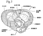
心臓は、4つの弁(図2及び3参照)を有し、これらの弁は、血液が心臓周期の間、誤った方向に流れないこと;すなわち、血液が、心室から対応する心房内へと逆流しないこと、あるいは心房から対応する心室内へと逆流しないことを、確実にする。左心房と左心室との間の弁は、僧帽弁である。右心房と右心室との間の弁は、三尖弁である。肺動脈弁は、肺動脈の開口部にある。大動脈弁は、大動脈の開口部にある。 The heart has four valves (see FIGS. 2 and 3) that prevent blood from flowing in the wrong direction during the cardiac cycle; that is, blood from the ventricle into the corresponding atrium. Ensure that there is no backflow or backflow from the atria into the corresponding ventricles. The valve between the left atrium and the left ventricle is the mitral valve. The valve between the right atrium and the right ventricle is a tricuspid valve. The pulmonary valve is at the opening of the pulmonary artery. The aortic valve is at the opening of the aorta.
心室性拡張期(すなわち、心室充填)の開始時(図2参照)には、大動脈弁及び肺動脈弁は閉じて、動脈から心室への逆流を防止する。その直後、心房から対応する心室への流れを可能にするために(図2に示すように)三尖弁及び僧帽弁が開く。心室収縮(すなわち、心室を空にすること)の開始直後に、−−心室から対応する心房への逆流を防止するために−−三尖弁及び僧帽弁が閉じ(図3参照)、対応する心室から動脈に血液を排出させることができるように大動脈弁及び肺動脈弁が開く。 At the beginning of ventricular diastole (ie, ventricular filling) (see FIG. 2), the aortic and pulmonary valves close to prevent backflow from the artery to the ventricle. Immediately thereafter, the tricuspid and mitral valves open (as shown in FIG. 2) to allow flow from the atria to the corresponding ventricles. Immediately after the onset of ventricular contraction (ie emptying the ventricle)-to prevent backflow from the ventricle to the corresponding atrium--the tricuspid and mitral valves close (see FIG. 3) The aortic and pulmonary valves open so that blood can be drained from the ventricle into the artery.
心臓弁の開閉は、主として、圧力差の結果として起こる。例えば、僧帽弁の開閉は、左心房と左心室との間の圧力差の結果として起こる。心室拡張期の間、心室が弛緩する場合に、肺静脈から左心房内への血液の静脈還流は、心室内の圧力を超える圧力を心房内に引き起こす。その結果、僧帽弁が開き、血液を心室に入れることができる。心室収縮期の間、心室が収縮するにつれて、心室内の圧力が、心房内の圧力より高くなり、僧帽弁を押して閉じる。 The opening and closing of the heart valve occurs mainly as a result of the pressure difference. For example, the opening and closing of the mitral valve occurs as a result of the pressure difference between the left atrium and the left ventricle. During ventricular diastole, when the ventricle relaxes, venous return of blood from the pulmonary vein into the left atrium causes pressure in the atrium that exceeds the pressure in the ventricle. As a result, the mitral valve opens and blood can enter the ventricle. During the ventricular systole, as the ventricle contracts, the pressure in the ventricle becomes higher than the pressure in the atrium and pushes the mitral valve closed.
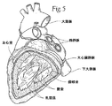
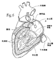
僧帽弁及び三尖弁は、コラーゲンの線維性のリングによって画定され、これらの各々は、弁輪部と称され、心臓の線維状骨格の一部を形成する。これらの輪部は、僧帽弁の2つの尖又は弁尖(前尖及び後尖と称される)、ならびに三尖弁の3つの尖又は弁尖を取り付けるためのものである。これらの弁尖は、1つより多くの乳頭筋から腱索を受け取る。健常な心臓では、これらの筋肉及びその腱索が、僧帽弁及び三尖弁を支持し、弁尖が、左右の心室の収縮(ポンピング)の間に発生する高い圧力に耐えることができる。図5及び6は、僧帽弁を支持する、左心室内の腱索及び乳頭筋を示す。 The mitral and tricuspid valves are defined by a fibrous ring of collagen, each of which is called the annulus and forms part of the fibrous skeleton of the heart. These annulus are for attaching the two cusps or leaflets of the mitral valve (referred to as the anterior leaflet and the posterior leaflet) and the three leaflets or leaflets of the tricuspid valve. These leaflets receive chords from more than one papillary muscle. In a healthy heart, these muscles and their chords support the mitral and tricuspid valves, which can withstand the high pressures that occur during left and right ventricular contractions (pumping). Figures 5 and 6 show the chords and papillary muscles in the left ventricle that support the mitral valve.
図2及び3に示すように、僧帽弁輪の前部は、大動脈弁の非冠動脈弁尖の近傍にある。また、図2及び3に示すように、僧帽弁輪は、左冠状動脈の回旋枝(左心房、左心室の不定部分に血液を供給し、及び多くのヒトの場合洞結節にも供給する)及び房室結節(洞結節と共に心周期を調整する)等の、その他の重要な心臓構造の付近にある。 As shown in FIGS. 2 and 3, the anterior portion of the mitral annulus is in the vicinity of the non-coronary leaflet of the aortic valve. Also, as shown in FIGS. 2 and 3, the mitral annulus provides blood to the left coronary artery (the left atrium, the indeterminate part of the left ventricle, and in many cases also the sinus node). ) And atrioventricular node (which adjusts the cardiac cycle with the sinus node), and so on.
また、後部僧帽弁輪の近傍には、冠状静脈洞とその分枝も存在する。これらの血管は、左冠状動脈により血液が供給される心臓の領域から血液を排出させる。冠状静脈洞及びその分枝は、冠状静脈血の約85%を受け取る。この冠状静脈洞は、右心房の後部、卵円窩の前下方に流入する(図4参照)。後部僧帽弁輪の大部分に平行して走る冠状静脈洞の分岐は、大心臓静脈と称され、平均して9.64±3.15mm離れて僧帽弁輪後部の上方に存在する。 There is also a coronary sinus and its branches near the posterior mitral annulus. These blood vessels drain blood from the region of the heart that is supplied with blood by the left coronary artery. The coronary sinus and its branches receive about 85% of the coronary venous blood. The coronary sinus flows into the posterior part of the right atrium, in front of and below the foveal fossa (see FIG. 4). The branch of the coronary sinus that runs parallel to the majority of the posterior mitral annulus, referred to as the great cardiac vein, is located above the posterior mitral annulus by an average of 9.64 ± 3.15 mm.
(II.僧帽弁機能不全の特徴及び原因)
左心室が左心房からの血液で満たされた後に収縮する場合、心室の壁は内側に動いて、乳頭筋及び索からの張力をいくらか解放する。血液が僧帽弁弁尖の下面に向かって押し上げられると、弁尖を僧帽弁の輪部の面へ向けて上げる。弁尖が輪部に向かうと、前部及び後尖の先端は一緒に合わさり、弁の密閉及び閉鎖を形成する。健常な心臓では、弁尖の接合は、僧帽弁輪の面近傍で生じる。血液は、大動脈に排出されるまで左心室中で加圧され続ける。乳頭筋の収縮は心室の収縮と共に同時に起こり、心室により与えられるピーク収縮圧力において健常な弁尖をきつく閉じられた状態にて維持するのに役立つ。
(II. Characteristics and causes of mitral valve dysfunction)
When the left ventricle contracts after being filled with blood from the left atrium, the ventricular wall moves inward, releasing some tension from the papillary muscles and cord. As blood is pushed up toward the lower surface of the mitral valve leaflet, the valve leaflet is raised toward the face of the mitral valve annulus. As the leaflet is directed to the annulus, the tips of the front and rear leaflets join together to form a valve seal and closure. In a healthy heart, valve leaflet junctions occur near the face of the mitral annulus. Blood continues to be pressurized in the left ventricle until it is drained into the aorta. Papillary muscle contraction occurs simultaneously with ventricular contraction and helps maintain a healthy leaflet tightly closed at the peak contraction pressure imparted by the ventricle.
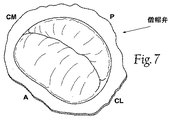
健常な心臓(図7及び8参照)では、僧帽弁輪の外形寸法により弁尖を接合させてピーク収縮圧力にて密着接合を形成させるような解剖学的形状及び張力が作り出される。弁尖が輪部の向かい合う内側の面及び外側の面において接合する位置は、弁尖交連と称される。 In a healthy heart (see FIGS. 7 and 8), an anatomical shape and tension is created that joins the leaflets according to the external dimensions of the mitral annulus and forms a tight junction at peak contraction pressure. The position at which the leaflets join at the inner and outer surfaces facing each other is called leaflet commissure.
弁の機能不全は、腱索(索)が伸長され、そしていくつかの場合には引き裂かれることによって生じ得る。索が裂けると、その結果として、弁尖が動揺する。また、通常の構造の弁は、弁輪の拡大又は変形に起因して、適切に機能しないおそれがある。この状態は、輪部の拡張と称され、一般に、心臓の筋肉の不全から生じる。さらに、その弁は、生まれつき不具合が生じていることもあるし後天的な疾患により不具合を生じることもある。 Valve dysfunction can be caused by the chords (strands) being stretched and in some cases torn. As a result of the tearing of the cord, the leaflet sways. Further, a valve having a normal structure may not function properly due to expansion or deformation of the annulus. This condition is referred to as dilation of the limbus and generally results from heart muscle failure. In addition, the valve may be inherently defective or may be defective due to an acquired disease.
原因が何であっても(図9参照)、僧帽弁の機能不全は、弁尖がピーク収縮圧力において接合しない場合に起こり得る。図9が示すように、心室収縮時の2つの弁尖の接合線はしっかり閉じられていない。その結果、左心室から左心房内に血液が流れ、好ましくない逆流が起こり得る。 Whatever the cause (see FIG. 9), mitral valve dysfunction can occur when the leaflets do not join at peak systolic pressure. As FIG. 9 shows, the joint line of the two leaflets during ventricular contraction is not tightly closed. As a result, blood can flow from the left ventricle into the left atrium and undesired reflux can occur.
僧帽弁の逆流は、左心室の収縮の間に、僧帽弁が血液を、左心室から左心房へと逆流させ得る状態である。このことは2つの重要な結果をもたらす。 Mitral regurgitation is a condition where the mitral valve can regurgitate blood from the left ventricle to the left atrium during contraction of the left ventricle. This has two important consequences.
第1に、心房へと戻ってくる血液は、高い心房圧力をもたらし、肺から左心房への血液の流れを減少させ得る。血液が肺系へと戻る場合、流体は肺へと漏れて肺水腫を引き起こす。 First, blood returning to the atria can cause high atrial pressure and reduce blood flow from the lungs to the left atrium. When blood returns to the pulmonary system, fluid leaks into the lungs causing pulmonary edema.
第2に、心房へと向かう血液容量が、大動脈内に向かう血液容量を減少させ、低心拍出量を引き起こす。各心周期の間、心房中の過剰な血液が心室をいっぱいにしすぎるため、心室は容量負荷となる。 Second, the volume of blood going to the atria reduces the volume of blood going into the aorta, causing low cardiac output. During each cardiac cycle, the ventricles become capacitively loaded because excess blood in the atria fills the ventricles too much.
僧帽弁の逆流は、コントラスト脳室造影法又は心エコードップラーアセスメントのいずれかにより、1+から4+の数値の等級尺度において測定される。等級1+は、普通の逆流で、ほとんど臨床的有意性がない。等級2+は、左心房へと不完全に戻ってくる逆向きの流れの噴出を示す。等級3は、肺静脈へと昇る逆向きの流れによって左心房を満たす逆流、及び3心拍数以下において消える反対方向の注入を示す。等級4の逆流は肺静脈への逆向きの流れを有し、3心拍数以下では心房から消えない反対方向の注入を有する。 Mitral regurgitation is measured on a numerical scale of 1+ to 4+, either by contrast ventricular angiography or cardiac ecdotler assessment. Grade 1+ is normal reflux with little clinical significance. Grade 2+ indicates a reverse flow eruption that returns incompletely to the left atrium. Grade 3 indicates regurgitation that fills the left atrium with a reverse flow up into the pulmonary veins and an infusion in the opposite direction that disappears at 3 heart rates or less. Grade 4 reflux has a reverse flow into the pulmonary veins and an infusion in the opposite direction that does not disappear from the atria below 3 heart rates.
僧帽弁の逆流は、2つの主要なタイプ、(i)器質的又は構造的なもの、及び(ii)機能的なもの、に分類される。器質的な僧帽弁の逆流は、収縮期に弁尖が上方へと動揺して液が漏れることを引き起こす構造的に異常な弁コンポーネントによりもたらされる。機能的な僧帽弁の逆流は、主として鬱血性の心臓の不具合によって輪部が膨張する結果としてもたらされ、後者はそれ自体通常、外科的には処置することが不可能であり、重症虚血又は主要な弁性の心疾患等の可逆的な原因によらない。 Mitral valve regurgitation is divided into two main types: (i) organic or structural, and (ii) functional. Organic mitral valve regurgitation is caused by structurally abnormal valve components that cause the leaflets to sway upward during systole causing fluid to leak. Functional mitral regurgitation is primarily the result of annulus expansion due to congestive heart failure, the latter itself usually not surgically treatable and severely ill Not due to reversible causes such as blood or major valvular heart disease.
器質的な僧帽弁の逆流は、分断された索又は腱乳頭筋によって弁尖が動揺し、そのため弁尖先の自由端部で密閉の崩壊が起こるときに見られるか;又は弁尖組織が厚ぼったくなると、弁が逸脱し、心室収縮の間、心房内まで上昇して接合が生じるレベルになり、さらに逸脱すると心房内の弁の開口位置が高くなって心房内で開口してしまう。 Organic mitral valve regurgitation is seen when the leaflet is swayed by a severed cord or tendon papillary muscle, thus causing a collapse of the seal at the free end of the leaflet; or When it becomes thicker, the valve deviates and rises into the atrium during ventricular contraction to a level where joining occurs, and when deviating further, the opening position of the valve in the atrium increases and opens in the atrium.
機能的な僧帽弁の逆流は、心臓の不具合によって二次的に起きる心臓及び僧帽弁輪の膨張の結果として生じ、ほとんどの場合、冠状動脈疾患又は特発性拡張型心筋症の結果として起こる。図7における健常な輪部を図9における不健康な輪部と比較すると、不健常な輪部は拡張し、特に、短軸に沿った前部から後部への距離が増加している。結果として、この輪部によって規定される形状及び張力は卵型ではなくなり(図7参照)、より円形となる(図9参照)。この状態を膨張と称する。輪部が拡張すると、ピーク収縮圧力時の接合をもたらしていたその形状及び張力は徐々に低下する。 Functional mitral regurgitation occurs as a result of dilatation of the heart and mitral annulus secondary to heart failure, most often as a result of coronary artery disease or idiopathic dilated cardiomyopathy . When comparing the healthy annulus in FIG. 7 with the unhealthy annulus in FIG. 9, the unhealthy annulus expands, and in particular, the distance from the front to the rear along the minor axis increases. As a result, the shape and tension defined by the ring portion are not oval (see FIG. 7) and become more circular (see FIG. 9). This state is called expansion. As the annulus expands, its shape and tension, which resulted in bonding at peak contraction pressure, gradually decrease.
線維性の僧帽弁輪は、その円周の3分の1において前部僧帽弁弁尖へと接触している。筋肉性の僧帽弁輪が、残りの僧帽弁輪を構成し、後部僧帽弁弁尖に接触している。前部線維性僧帽弁輪は、中心線維体と密接し、その2つの末端は線維三角と称される。各線維三角のちょうど後部には、前及び後交連の2つが存在する交連がある。交連とは輪部において前尖が後尖と出合う位置である。 The fibrous mitral valve annulus contacts the anterior mitral valve leaflet at one third of its circumference. A muscular mitral annulus constitutes the remaining mitral annulus and contacts the posterior mitral valve leaflet. The anterior fibrous mitral annulus is in intimate contact with the central fibrous body and its two ends are referred to as the fiber triangle. Just behind each fiber triangle is a commissure where there are two anterior and posterior commissures. The commissure is the position where the front leafe meets the rear leaflet in the ring.
上述されたように、中心線維体はまた、大動脈弁の無冠尖と密に関わる。この中心線維体は、僧帽弁輪膨張のプロセスの間、伸長に対し相当程度の耐性を有する。僧帽弁輪膨張の大部分は、筋肉性の輪部として知られている輪部の後部3分の2において起こることが示されている。このため、輪部が拡張する場合には前部僧帽弁弁尖に接触している割合が減少すると推論することができよう。 As mentioned above, the central fibrous body is also intimately associated with the aortic apex of the aortic valve. This central fibrous body has a considerable resistance to elongation during the process of mitral annulus inflation. Most of the mitral annulus expansion has been shown to occur in the rear two thirds of the annulus, known as the muscular annulus. For this reason, it can be inferred that when the annulus expands, the proportion of contact with the anterior mitral valve leaflet decreases.
機能的な僧帽弁逆流では、拡張された輪部が、心周期における全てのフェーズにおいて、弁尖が接合する点で後尖から前尖を引き離す。器質的又は機能的な僧帽弁逆流のいずれかにおける僧帽弁逆流の開始は、急性的であるか、又は徐々に且つ慢性的である。 In functional mitral regurgitation, the dilated annulus pulls the anterior leaflet away from the posterior leaflet at the point where the leaflet joins in all phases of the cardiac cycle. The onset of mitral regurgitation in either organic or functional mitral regurgitation is acute or gradual and chronic.
虚血性又は特発性の起源を有する拡張型心筋症においては、僧帽弁輪は拡張して機能的な僧帽弁逆流を引き起こし得る。鬱血性心不全の患者の約25%がそうである。運動時には、機能的な僧帽弁逆流の発生率が上昇して50%を超えることが心エコー検査によって示される。 In dilated cardiomyopathy with ischemic or idiopathic origin, the mitral annulus can dilate and cause functional mitral regurgitation. About 25% of patients with congestive heart failure are. During exercise, echocardiography shows that the incidence of functional mitral regurgitation is increased to over 50%.
機能的な僧帽弁逆流の患者の死亡率が、機能的な僧帽弁逆流を伴わない以外は同じである患者と比較して高いことからもわかるように、機能的な僧帽弁逆流は、拡張した心臓にとって極めて深刻な問題である。機能的な僧帽弁逆流がこれらの患者の状況を悪化させるメカニズムのひとつには、心室に負荷をかける容量過負荷の増大がある。直接的には液漏れが原因で、心臓は、心周期毎に大動脈弁を通じて血液を順行的に排出し、僧帽弁を通じて逆行的に排出することを実行しなければならず、それに伴って仕事量が増加する。僧帽弁からの逆行的排出は左心房排出の逆流画分と称される。これに前方排出画分を加えたものが総排出画分となる。正常な心臓は70%の前方排出画分を有する。機能的な僧帽弁逆流及び拡張型の心筋症を伴う場合における排出画分は、通常30%に満たない。後者の群において逆流性の画分が排出画分の半分である場合、この前方排出画分は15%程度の低いものであり得る。 As can be seen from the fact that the mortality rate of patients with functional mitral regurgitation is higher compared to patients who are the same except without functional mitral regurgitation, functional mitral regurgitation is This is a very serious problem for an expanded heart. One mechanism by which functional mitral regurgitation exacerbates the situation in these patients is an increase in volume overload that places a load on the ventricles. Directly due to fluid leakage, the heart must perform antegrade drainage of blood through the aortic valve and retrogradely through the mitral valve every cardiac cycle, Work volume increases. Retrograde drainage from the mitral valve is referred to as the reflux fraction of left atrial drainage. The sum of the forward discharge fraction is the total discharge fraction. A normal heart has a forward drainage fraction of 70%. The excretion fraction with functional mitral regurgitation and dilated cardiomyopathy is usually less than 30%. If the backflow fraction is half of the discharged fraction in the latter group, this forward discharged fraction can be as low as 15%.
(III.従来の処置手順)
僧帽弁逆流の処置において、利尿薬及び/又は血管拡張薬が、左心房内に逆流する血液の量を減少させることを補助するために使用され得る。その状態が投薬で安定化されない場合は、大動脈内バルーンカウンターパルセイションデバイスが使用される。慢性又は急性の僧帽弁逆流については、僧帽弁を修復又は交換するための手術が、しばしば必要とされる。
(III. Conventional procedure)
In the treatment of mitral regurgitation, diuretics and / or vasodilators can be used to help reduce the amount of blood that flows back into the left atrium. If the condition is not stabilized by medication, an intra-aortic balloon counterpulsation device is used. For chronic or acute mitral regurgitation, surgery is often required to repair or replace the mitral valve.
現在、僧帽弁外科手術のための患者の選抜基準は、非常に選択的である。患者は理想的には、正常な心室機能、全般的に良好な健康状態、及び3〜5年より長い予測寿命、NYHA分類III又はIVの症状、及び僧帽弁外科手術のための指標として少なくとも等級3の逆流を有しているものとされるであろう。僧帽弁修復が期待される場合、重篤な症状を伴う、より若年の患者には、早期の外科手術が指示され得る。最も知られた外科的な僧帽弁修復手順は、後尖のミドル・スカラップ上の分断された索による器質的な僧帽弁逆流に対するものである。 Currently, patient selection criteria for mitral valve surgery are very selective. Patients ideally have at least as indicators for normal ventricular function, overall good health, and expected life longer than 3-5 years, symptoms of NYHA class III or IV, and mitral valve surgery It will be assumed to have a grade 3 backflow. If mitral valve repair is expected, younger patients with severe symptoms may be instructed to undergo early surgery. The best known surgical mitral valve repair procedure is for organic mitral regurgitation due to a split cord on the middle scallop at the posterior leaflet.
従来の弁形成リング修復においては、後部輪の長さを、外科的な環状形成縫合環状カフを通過する縫合によって短くする。このような修復の目標は、よりよい接合を可能にさせるために後部僧帽弁弁尖を前尖へと向かわせることである。 In conventional annuloplasty ring repairs, the length of the posterior ring is shortened by suturing through a surgical annuloplasty suture annular cuff. The goal of such repair is to point the posterior mitral valve leaflet to the anterior leaflet to allow better bonding.
また、血管内で実行され得る外科的な端部−端部の接合修復も行われ、その場合、中間部弁尖は、中間弁尖縫合又はクリップに対して、弁尖におけるこれらの点を心周期の間一体に保持するために適用される。Edwards Life Sciences Corporation及びEvalve Inc.はそれぞれ、拍動している心臓における2つの僧帽弁弁尖をしっかりと捕捉しそれを結合する、経血管縫合及びクリップを開発している。 There is also a surgical end-to-end joint repair that can be performed within the blood vessel, in which case the intermediate leaflets center these points on the leaflets relative to the intermediate leaflet suture or clip. Applied to hold together during a cycle. Edwards Life Sciences Corporation and Evalve Inc. Have developed transvascular sutures and clips that securely capture and join the two mitral valve leaflets in the beating heart.
等級3+又は4+の器質的な僧帽弁逆流は、このような端部−端部の技法を用いて修復することができる。このことは、器質的な僧帽弁逆流においては、問題が輪部ではなく、主要な弁コンポーネントであることによる。 Grade 3+ or 4+ organic mitral regurgitation can be repaired using such end-to-end techniques. This is because in organic mitral regurgitation, the problem is not the annulus but the major valve component.
しかし、機能的な僧帽弁逆流は、特に、高い等級3+及び4+の機能的な僧帽弁逆流の場合には、端部−端部の修復後もなお高いレベルが維持される可能性がある。 However, functional mitral regurgitation may be maintained at a high level even after end-to-end repair, especially in the case of high grade 3+ and 4+ functional mitral regurgitation. is there.
別に現れている技法においては、冠状静脈洞内において単独で機能するために適用され収容される血管内の手段を通じて、冠状静脈洞が機械的に変形される。ヒトにおける初期の臨床報告は、僧帽弁輪を変形させるためのこれらの血管内冠状静脈洞技法が不可能であることを報告している。 In another emerging technique, the coronary sinus is mechanically deformed through intravascular means applied and contained to function alone within the coronary sinus. Early clinical reports in humans have reported that these intravascular coronary sinus techniques for deforming the mitral annulus are not possible.
鬱血性の心臓不具合を有する600万人のアメリカ人の25%が、同程度の機能的な僧帽弁逆流を有するであろうということが報告されている。これは機能的な僧帽弁逆流を有する150万人を構成する。これらのうちで特発性拡張型心筋症は600,000人を占める。残る900,000人のうち、約半数の虚血性疾患を有する人が、専ら拡張した輪部に起因する機能的な僧帽弁逆流を有している。 It has been reported that 25% of 6 million Americans with congestive heart failure will have comparable functional mitral regurgitation. This constitutes 1.5 million people with functional mitral regurgitation. Of these, idiopathic dilated cardiomyopathy accounts for 600,000 people. Of the remaining 900,000, about half have ischemic disease and have functional mitral regurgitation due solely to the dilated annulus.
進行性の機能的な僧帽弁逆流のサイクルを妨害することにより、外科的患者で、多くの患者における生存率が増加し、実際に前方排出画分が増加することが示されている。外科的療法に伴う問題点は、高い罹患率及び外科的修復に関連する高い死亡率を伴うこれらの慢性疾患患者に課せられる、激しい損傷である。 Interfering with the cycle of progressive functional mitral regurgitation has been shown to increase survival in many patients and indeed increase the forward drainage fraction in surgical patients. The problem with surgical therapy is the severe damage imposed on patients with these chronic diseases with high morbidity and high mortality associated with surgical repair.
心臓弁の機能不全、例えば器質的な及び機能的な僧帽弁逆流の処置等のための、簡便で経済効果を有する非浸潤的なデバイス、システム及び方法へのニーズが残っている。 There remains a need for a simple and economical non-invasive device, system and method for the treatment of heart valve dysfunction, such as organic and functional mitral regurgitation.
(発明の概要)
本発明は、別々であって、はっきりと区別できるが、所望であれば、使用するために組み合わせることもできる各種態様を包含する。
(Summary of Invention)
The present invention encompasses various aspects that are separate and clearly distinguishable, but can be combined for use if desired.
本発明の一態様は、大心臓静脈内に位置するアンカー構造物を用いた、僧帽心臓弁を処置するためのデバイス、システム、及び方法を提供する。 One aspect of the present invention provides devices, systems, and methods for treating a mitral heart valve using an anchor structure located within a large heart vein.
一実施形態において、本デバイス、システム、及び方法は、僧帽弁の後部輪の少なくとも一部を含む長さに隣接して大心臓静脈内にアンカー構造物を設置する。本デバイス、システム、及び方法は、移植物の後部領域を大心臓静脈内のアンカー構造物に結合し、移植物を、左心房を横切るように、心房中隔を通じて、及び右心房内へ拡張する。本デバイス、システム、及び方法は、この移植物に張力を及ぼし、張力が維持されるために右心房中又は近傍の組織に、移植物の前部領域を固定する。移植物に働く張力は、弁の中隔−外側の大きさを向上させ、それにより、機能性の僧帽弁逆流を改善するために弁尖の接合向上をもたらし得る。器質的な僧帽弁逆流の場合、移植物に働く張力が、心周期中に弁形成リングが弁輪の大きさの変化に抵抗するように、後部弁輪を安定化させるために機能し得る。 In one embodiment, the device, system, and method place an anchor structure in the great heart vein adjacent to a length that includes at least a portion of the posterior annulus of the mitral valve. The devices, systems, and methods couple the posterior region of the implant to an anchor structure in the great cardiac vein and expand the implant through the atrial septum and into the right atrium across the left atrium. . The devices, systems, and methods apply tension to the implant and secure the anterior region of the implant in or near the right atrium to maintain the tension. The tension acting on the implant may increase the septal-lateral size of the valve, thereby providing improved leaflet joints to improve functional mitral regurgitation. In the case of organic mitral regurgitation, the tension acting on the implant can function to stabilize the posterior annulus so that the annuloplasty ring resists changes in the annulus size during the cardiac cycle. .
一実施形態において、アンカー構造物は、統合された物理的構造物中に大心臓静脈をその長さに沿って連結させるためにも機能し得る。この配置において、移植物に働く張力は、僧帽弁の後部輪に隣接した心房組織から連結された大心臓静脈まで、力ベクトルとして均一に分布している。組織の連結は、移植物の有益な効果を増大し得る。 In one embodiment, the anchor structure may also function to connect the great cardiac vein along its length in an integrated physical structure. In this arrangement, the tension acting on the implant is evenly distributed as a force vector from the atrial tissue adjacent to the posterior ring of the mitral valve to the connected great cardiac vein. Tissue coupling can increase the beneficial effects of the implant.
一実施形態において、本デバイス、システム、及び方法は、連結される大心臓静脈と左心室との間の組織領域において、大心臓静脈と左心室とを結合させる。この配置において、張力が及ぶ状態で、移植物は、大心臓静脈内の組織連結アンカー構造物上に力ベクトルが働くように構成される。力ベクトルは、上向き、内向き、又は両方の組み合わせであり得る。力ベクトルは、弁輪への張力を軽減するように、左心室に対して、結合した組織領域によって指示される。前述同様に、得られる有益な効果はそのことによりさらに増大され得る。 In one embodiment, the devices, systems, and methods combine the great heart vein and the left ventricle in a tissue region between the connected great heart vein and the left ventricle. In this arrangement, under tension, the implant is configured such that a force vector acts on the tissue-linked anchor structure in the great cardiac vein. The force vector can be upward, inward, or a combination of both. The force vector is directed by the connected tissue region to the left ventricle to relieve tension on the annulus. As before, the resulting beneficial effects can be further increased thereby.
本発明の別の態様は、僧帽弁の後部輪に隣接する大心臓静脈内で、張力状態で、環状経路で展開されるような大きさ及び構成にされている細長い構造物を使用した、僧帽心臓弁を処置するためのデバイス、システム、及び方法を提供する。この構造物は冠状静脈洞から右心房内へと延在するような大きさ及び構成にされている末端アンカー領域を含む。アンカーは右心房内の心房中隔上に末端アンカー領域を結合させる。移植物に働く張力は、弁の中隔−外側の大きさを向上させ、それにより、機能性の僧帽弁逆流を改善するために弁尖の接合向上をもたらし得る。器質的な僧帽弁逆流の場合、移植物に働く張力が、心周期中に弁形成リングが弁輪の大きさの変化に抵抗するように、後部弁輪を安定化させるために機能し得る。 Another aspect of the invention uses an elongated structure that is sized and configured to be deployed in a tensioned, annular path within the great cardiac vein adjacent to the posterior annulus of the mitral valve. Devices, systems, and methods for treating a mitral heart valve are provided. The structure includes a distal anchor region sized and configured to extend from the coronary sinus into the right atrium. The anchor connects the terminal anchor region on the atrial septum within the right atrium. The tension acting on the implant may increase the septal-lateral size of the valve, thereby providing improved leaflet joints to improve functional mitral regurgitation. In the case of organic mitral regurgitation, the tension acting on the implant can function to stabilize the posterior annulus so that the annuloplasty ring resists changes in the annulus size during the cardiac cycle. .
本発明の別の態様は、大心臓静脈内の少なくとも一部にループとして展開されるような大きさ及び構成にされている細長い構造物を使用した、僧帽心臓弁を処置するためのデバイス、システム、及び方法を提供する。この配置では、細長い構造物は第1及び第2の末端アンカー領域を含む。この細長い構造物は、第1及び第2の末端アンカー領域と結合した中間領域も含む。それぞれの末端アンカー領域は、使用時に右心房へと延在するような大きさ及び構成にされており、一方、中間領域は、僧帽弁の後部輪に隣接する大心臓静脈内で、環状経路で右心房の外側に延在するような大きさ及び構成にされている。アンカーは右心房内に第1及び第2の末端アンカー領域を結合させるか、又は、大心臓静脈内で、張力状態で、大静脈を中間領域に保持させる。移植物に働く張力は、弁の中隔−外側の大きさを向上させ、それにより、機能性の僧帽弁逆流を改善するために弁尖の接合向上をもたらし得る。器質的な僧帽弁逆流の場合、移植物に働く張力が、心周期中に弁形成リングが弁輪の大きさの変化に抵抗するように、後部弁輪を安定化させるために機能し得る。 Another aspect of the present invention is a device for treating a mitral heart valve using an elongated structure sized and configured to be deployed as a loop in at least a portion of the great heart vein, Systems and methods are provided. In this arrangement, the elongate structure includes first and second end anchor regions. The elongate structure also includes an intermediate region coupled to the first and second end anchor regions. Each distal anchor region is sized and configured to extend into the right atrium when in use, while the intermediate region is within the great cardiac vein adjacent to the posterior annulus of the mitral valve, an annular pathway And sized and configured to extend outside the right atrium. The anchor couples the first and second terminal anchor regions into the right atrium or holds the vena cava in the middle region in tension in the great heart vein. The tension acting on the implant may increase the septal-lateral size of the valve, thereby providing improved leaflet joints to improve functional mitral regurgitation. In the case of organic mitral regurgitation, the tension acting on the implant can function to stabilize the posterior annulus so that the annuloplasty ring resists changes in the annulus size during the cardiac cycle. .
本発明の別の態様は、心腔内に移植物を配置するためのデバイス、システム、及び方法を提供する。第1の移植物は心腔に隣接した心臓血管内に展開され、第2の移植物は心腔内に展開される。本発明の態様に従って、心腔内の第2の移植物の領域は、例えば、この第2の移植物の領域が心臓血管内の第1の移植物の領域と結合し得るように、心臓血管内の第1の移植物の領域に磁気的に引き付けられる。 Another aspect of the present invention provides devices, systems, and methods for placing an implant within a heart chamber. The first implant is deployed in a cardiovascular vessel adjacent to the heart chamber, and the second implant is deployed in the heart chamber. In accordance with an aspect of the present invention, the region of the second implant in the heart chamber is, for example, a cardiovascular such that the region of the second implant can be combined with the region of the first implant in the cardiovascular. It is magnetically attracted to the region of the first implant within.
本発明のその他の特徴及び利点は、添付された明細書、図面、及び特許請求の範囲に基づき明らかとなるであろう。 Other features and advantages of the invention will be apparent based on the accompanying specification, drawings, and claims.
(詳細な説明)
本明細書の開示は、当業者が本発明を実施することを可能にするために、詳細かつ正確であるが、本明細書中に開示される実際の実施形態は、本発明を単に例示するのみであり、本発明は、他の特定の構造で実施され得る。好ましい実施形態が記載されるが、細部は、特許請求の範囲によって規定される本発明から逸脱することなく、変更され得る。
(Detailed explanation)
While the disclosure herein is detailed and accurate to enable those skilled in the art to practice the invention, the actual embodiments disclosed herein are merely illustrative of the invention. However, the present invention may be implemented with other specific structures. While preferred embodiments are described, details may be changed without departing from the invention, which is defined by the claims.
(I.心臓弁輪短軸の直接的短縮化のための中隔横断移植物)
(A.移植物の構造)
図10A及び10Bは、通常は前部から後部への方向で僧帽弁輪を橋渡しして、左心房を横切って延在するような大きさ及び構成にされた移植物10の実施形態を示す。移植物10は、後部組織アンカー領域14及び前部組織アンカー領域16を有する橋渡し領域、すなわち、ブリッジエレメント12を備える。
(I. Transseptal implant for direct shortening of the short axis of the heart valve annulus)
(A. Structure of transplant)
FIGS. 10A and 10B illustrate an embodiment of an
後部アンカー領域14は、僧帽弁の後部輪の上側の心房組織領域内に固定するような大きさ及び構成にされている。後部輪の位置又は隣接する組織領域内よりも、後部アンカー領域14のしっかりとした足掛かりを得るためにより多くの組織体積を通常提供することから、この領域が好ましい。この輪上部位置での係合は、冠動脈回旋枝への侵襲及び損傷リスクも回避する。
The
前部アンカー領域16は、右心房から中隔内に到達させるとき、右心房内又は近傍の組織に固定するような大きさ及び構成にされている。例えば、図10A及び10Bに示されるように、前部アンカー領域16は、心房中隔内の繊維性組織領域に固定してもよい。示されるように、アンカー部位は、望ましくは、後部組織アンカー領域14の高さと大体同じ高さ又はより高い位置にある前部輪よりも上にある。図示された実施形態において、前部アンカー領域16は、卵円窩の下縁の位置又は近傍に固定されている。後述するように、前部アンカー領域16は、アンカー部位が組織領域を損傷しないという条件で、卵円窩から離れた、中隔内のより上又は下の位置に固定することもできる。
The
より詳細に後述するように、別の実施形態においては(例えば、図33B及び33Cを参照されたい)、前部アンカー領域16は、中隔から右心房内に到達させる場合、中隔自体に対する代わりに、上大静脈(SVC)又は下大静脈(IVC)内に固定又はさもなければこれらと拘束してもよい。
As will be described in more detail below, in another embodiment (see, eg, FIGS. 33B and 33C), the
使用時に、橋渡し領域、すなわち、ブリッジエレメント12は、2つの組織アンカー領域14と16との間で、張力状態で配置することができる。それにより、移植物10は、通常は左心房を横切り後部から前部の方向で直接的機械力が働くように機能する。この直接的機械力は、弁輪の短軸を短縮化するために機能し得る。その際に、移植物10は、弁輪の主軸に沿って弁輪を受動的に変形することができ且つ/又はその他の周囲の解剖学的構造物を受動的に変形することができる。しかしながら、移植物10の存在が、短軸又は主軸の長さに影響を及ぼすことなく、心臓弁輪に隣接する組織を安定化するために機能し得ることは十分理解されるべきである。
In use, the bridging region, i.e. the
その他の弁構造物に位置する場合、影響が及ぼされる軸は、周囲の解剖学的状況により、「主軸」及び「短軸」でないかもしれないことは十分理解されるべきである。治療的であるためには、心室収縮開始時に心臓には最も血液が充満しており、大部分の僧帽弁漏出が生じる、心周期の一部の間、例えば、拡張後期及び収縮初期に、移植物10は、弁輪を変形させることのみを必要とし得ることは十分理解されるべきである。例えば、移植物10は、弁輪が拡張し、移植物10によって制約を受けるようになる場合、心室拡張後期弛緩中に弁輪の内側への動きを復元又は増大させるために、小さな又は無視し得る弁輪の変位を生じさせるための大きさであってもよい。左心房を横切って移植物10に働く機械力は、心臓弁輪及び弁尖をより正常な解剖学的形状及び張力状態に復元し得る。このより正常な解剖学的形状及び張力状態は、後期心室拡張期及び初期心室収縮期中の弁尖の接合を促し、言い換えると、僧帽弁逆流を減少させる。
It should be appreciated that when located in other valve structures, the affected axis may not be the “major axis” and “short axis” depending on the surrounding anatomical context. To be therapeutic, the heart is most blood-filled at the beginning of ventricular contraction and most mitral valve leakage occurs, for example during the part of the cardiac cycle, for example during late diastole and early systole It should be appreciated that the
その多くの基本的形態において、移植物10は、生体適合性の金属若しくは高分子材料、又は、適切にコーティング、含浸、若しくは材料に生体適合性を付与するためのその他の処理を行いうる金属若しくは高分子材料、或いは、これらの材料の組み合わせから製造される。この材料はさらに、望ましくは、放射線不透過性であるか、又は、X線透視による視覚化を容易にするために放射線不透過特性が取り入れられる。移植物10は、可撓性若しくは剛性、又は非弾性若しくは弾性、或いはこれらの組み合わせの機械的特性を有し得る金属又は高分子のワイヤー状構造物の曲げ、成形、接合、機械加工、鋳造、又は押し出しにより製造し得る。或いは、移植物10は金属又は高分子の糸状又は縫合材料から製造し得る。移植物10を製造し得る材料として、ステンレス・スチール、ニチノール、チタニウム、シリコーン、メッキ金属、eljiloy、及びNP55が挙げられる。
In its many basic forms, the
移植物10は各種形状を取ることができ、各種断面幾何を有することができる。移植物10は、例えば、概して曲線である(すなわち、円形又は楕円形の)断面、又は概して直線的な断面(すなわち、正方形又は長方形)、又はこれらの組み合わせを有することができる。
The
(1.後部アンカー領域)
後部組織アンカー領域14は、弁輪の上側の位置にある左心房内組織と係合するための、すなわち、後部輪の上側の左心房壁内組織と係合するための、大きさ及び構成にされている。
(1. Rear anchor region)
The posterior
図示された実施形態において、大半の僧帽弁の後部輪と隣接して且つ並行して流れる大心臓静脈と通常は同じ位置にある組織と、後部アンカー領域14とが、係合することが示されている。この冠状静脈洞の支流は、その中に放射線不透過性のデバイスを配置するか、又は、その中に造影剤を注入した場合に、強力且つ信頼し得るX線透視指標を提供し得る。先述の通り、この弁輪の上側の位置での組織の係合は、僧帽弁輪に直接適用する方法と比較して、冠動脈回旋枝の侵襲リスク及び損傷リスクも減少させる。
In the illustrated embodiment, the
相対的に薄い非繊維性の心房組織を容易に増強及び連結し得る部位も、大心臓静脈は提供する。本質的に非繊維性の心臓組織における後部組織アンカー領域14の保持力又はしっかりとした足掛かりを増大させるために、後部組織アンカー領域14は、大心臓静脈内に配置された後部アンカー18と結合させることができる。このことによって、十分な期間中断することなく、臨床的に適切な時間枠で現れる、評価し得るその組織への保持力又はしっかりとした足掛かりをいずれにせよ維持するように、心臓の非繊維性部分における後部アンカー領域14の機械的固定化を可能にする。
The great cardiac vein also provides a site that can easily augment and connect relatively thin non-fibrous atrial tissue. In order to increase the retention force or firm footing of the posterior
一実施形態において(図10A参照)、後部アンカー18は、通常は垂直の関係で後部アンカー領域14と一体的に結合している、T型を形成する移植物10の一体部分を備える。この配置では、後部アンカー18はT型のクロスアームを備える。後部アンカー18は、後部アンカー領域14から内側及び外側の方向で、大心臓静脈の少なくとも一部内部を縦走するために十分細長い。
In one embodiment (see FIG. 10A), the
この配置では、後部アンカー18は、後部アンカー領域14上に、左心房から組織貫通針の内腔を通じ、大心臓静脈壁を通じて、ゆったりとした、折り畳まれた状態で挿入することができる。後部アンカー18は、針の内腔から一度解放されたら、大心臓静脈内に位置するように、折り畳まれた状態からT型に分かれて開くような弾性記憶を有して構成され得る。この配置では、後部アンカー18は、約0.5mmの直径を有し得る。
In this arrangement, the
図10Bに示される実施形態において、後部アンカー18は、移植中に後部アンカー領域14と結合する別の構造物を備える。このタイプの後部アンカー18が貫通するように配置し得る、右心房から接近可能な血管内部位を、冠状静脈洞は提供する。
In the embodiment shown in FIG. 10B, the
図10Bに示される実施形態において、後部アンカー18は機械的ステント様構造物を備える。このステント様構造物は、望ましくは、後部アンカー領域14に対する大きな物理的且つ放射線不透過性の標的、又は、大心臓静脈内に存在するアンカー構造物に進入若しくは結合しようとするいずれか他の心房内デバイス、を提供するために、比較的大きい(例えば、直径が少なくとも10mm〜20mm)。所望される大きな物理サイズの後部アンカー18はさらに、より小さな構造物が大心臓静脈内に配置された場合と比較して、冠動脈回旋枝を損傷させる確率を減少させる。より小さな物理標的はより簡単に見失い得るし、周辺組織に対する損傷を生じ得る。当然、より小さな構造物(例えば、直径約5mm)又はより大きな構造物(例えば、直径約30mm)も、意図される特定の治療目的に応じて、使用のために選択することもできた。
In the embodiment shown in FIG. 10B, the
大心臓静脈と同じ高さの位置、それよりも上側、又は下側に位置する、例えば、僧帽弁の後部輪の面よりも約5〜約25mmの範囲上側に位置する非繊維性組織は、その他の方法で強化及び連結させ得ることは十分理解されるべきである。例えば、組織膨張性物質、又は、例えば、化学的若しくは熱によって引き起こされる線維形成を利用することにより、後部組織アンカー領域14によるしっかりとした足掛かり又は保持のために、弁輪の上側の心房組織を強化及び連結させることができる。
Non-fibrous tissue located at the same height as the great heart vein, above or below it, for example, in the range of about 5 to about 25 mm above the face of the posterior ring of the mitral valve, It should be appreciated that other methods can be strengthened and connected. For example, the atrial tissue on the upper side of the annulus can be used for firm footing or retention by the posterior
(2.前部アンカー領域)
前部アンカー領域16は、心房中隔の右心房側における繊維性組織及び周辺組織としっかりと係合するような大きさ及び構成にされている。この繊維性組織領域は、デバイスがそれを通じて引っ張られる点において、筋肉よりもより良い完全性を示す組織固定部位を提供する。繊維自体の程度の点で、中隔が、心臓において最も繊維性の組織構造物である。外科的な操作をした場合、通常は、中隔が、縫合糸をその中に実際に配置することができ、並びに、pledgetts又はそれが求められる筋肉組織中深く捕捉されることなく保持されることが期待できる、唯一の心臓組織の一つである。
(2. Front anchor region)
The
図10に示されるように、前部組織アンカー領域16は、僧帽弁の前部輪面上側の弁輪上の位置で中隔壁を貫通する。前部側の弁輪上の距離は、通常、後部側における弁輪上の距離の位置又はその上であり得る。先に指摘したように、前部組織アンカー領域16は、図10において卵円窩の下縁の位置又は近傍に示されるが、中隔組織及び周辺構造物への損傷防止を考慮した場合、卵円窩の内側又は外側の他のより下側又はより上側の部位を使用することができる。
As shown in FIG. 10, the anterior
左心房から十分外側であり、前部輪の十分上側に離れている、右心房内の弁輪の上側の位置で組織を係合することにより、移植物10は、前部が前尖によって、後部が大動脈流出路によって、中央部が伝導系の房室結節によって結合している非常に薄い弁輪組織の縁のみが存在する、前部輪の位置又は隣接する位置での非現実的な血管内での結合を回避する。前部輪は、大動脈弁の非冠動脈弁尖が、中心の繊維体を通じて僧帽弁輪と結合している場所である。右心房内の弁輪の上の位置での移植物10前部の固定(中隔又は大静脈内のいずれかに対して)は、大動脈弁及び房室結節両方に対する侵襲及び損傷リスクを回避する。
By engaging tissue at a position above the annulus in the right atrium that is well outside the left atrium and well above the anterior ring, the
繊維性の中隔組織における前部組織アンカー領域16のしっかりとした足掛かりは、望ましくは、1以上の前部アンカー20によって増大される。前部アンカー20又は複数の前部アンカー20は、繊維性組織部位における前部アンカー領域16の保持力又はしっかりとした足掛かりを機械的に増大させる。前部アンカー20又は複数の前部アンカー20は、望ましくは、少なくとも部分的に、中隔に隣接する解剖学的構造物のアンカーに対する依存、緩衝をも増大させ、移植物10の位置を固定する。ピンポイントでの引っ張り力がアンカー領域16から中隔に働くことを見越して、アンカー20に働く力は、弁、血管又は伝導組織に緩衝を生じさせることなく、緩やかな面の上に広げるべきである。さらに、アンカー20は、心臓内に展開されるデバイスのために血栓形成を減少させる低プロファイル構造及び高度に洗浄可能な表面を有するべきである。より詳細に後述するように、力を中隔に沿って均一に分布させるために、中隔ブレースを前部アンカー20又は複数の前部アンカー20と組み合わせて使用してもよい(図33A参照)。或いは、中隔に直接固定する代わりに、IVC又はSVC内のステントをアンカー部位として使用することができる(図33B及び33C参照)。
The firm foothold of the anterior
放射線不透過性アンカー及び境界の明瞭なX線透視指標を有する後部及び前部組織アンカー領域14及び16それぞれの、直前に記述した弁輪の上側の組織への固定は、重要な構造物、例えば、回旋動脈、房室結節、及び大動脈弁の左冠尖及び無冠尖に対する損傷の回避をもたらすばかりでなく、弁輪の上側の固定部位は、組織との間のしっかりとした足掛かり並びに直接的に張力が及んで貫通/咬合/保持する組織結合機構に依存しない。その代わり、機械的レバーの結合により対応し、それにより強力な組織せん断力がより分布し得る、ステントのような物理的構造物及び力分布機構を使用することができる。さらに、この固定部位は、オペレーターが複雑な撮像を使用することを必要としない。移植後又は移植中の移植物位置の調整も、これらの制約を受けずに、容易化される。この固定部位は、さらに、血管内で引き付けて、次いで、それが現れる左心房壁の側面のいずれかにおいてブリッジエレメントを切断することにより、移植物10の心房内での完全な回収を可能にする。
The fixation of the posterior and anterior
(3.橋渡し領域の方向性)
図10に示される実施形態において、移植物10は、僧帽弁輪の中間点の近くよりも上側の後部アンカー点に始まり、通常は直線経路で中隔内の前部アンカー領域に直接前方方向に進行して左心房を橋渡ししていることが示されている。図10に示されるように、橋渡し領域、すなわち、移植物10のブリッジエレメント12は、予め形成されるか、さもなければ、アンカーの後部及び前部領域間の高さの違いによって影響されること以外は、弁輪の面に向かう又は離れる有意な高さの偏差も無く、弁の面の上側に本質的には直線経路で延在するために構成される。
(3. Direction of the bridge area)
In the embodiment shown in FIG. 10, the
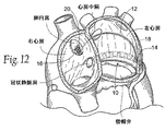
所望であれば、移植物10が及ぼす力ベクトル又は複数の力ベクトルの特性及び方向に影響を与えるために、この経路において外側又は内側の偏差及び/又は上方又は下方の偏差が与えられ得ることは十分理解されるべきである。橋渡し領域、すなわち、ブリッジエレメント12は予め形成させるか、さもなければ、特定の治療的必要性及び患者の形態を考慮した場合、標的とする弁輪及び/又は心房構造物の再形成を達成するために様々な外側/内側及び上方/下方偏差を有して構成させることができる。
If desired, it is possible that an outer or inner deviation and / or an upper or lower deviation can be given in this path in order to influence the characteristics and direction of the force vector or force vectors exerted by the
例えば、図11に示されるように、移植物10は、弁輪の三角部の外側近くに位置する(すなわち、中隔からはより遠い)アンカー後部領域から始まり、左心房を橋渡しすることが示されている。或いは、アンカーの後部領域は、弁輪の三角部の内側により近くに位置することができる(すなわち、中隔により近い)。これらのアンカー後部領域のいずれか一方から、移植物10は、直線経路で中隔内の前部アンカー領域に直接前方に延在し得る。図11に示されるように、図10同様、橋渡し領域、すなわち、移植物10のブリッジエレメント12は、予め形成されるか、さもなければ、もしある場合には、アンカーの後部及び前部領域間の高さの違いによって影響されること以外は、弁輪の面に向かう又は離れる有意な高さの偏差も無く、弁の面の上側に本質的には直線経路で延在するために構成される。
For example, as shown in FIG. 11, the
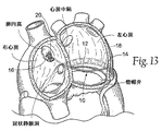
特定の位置のアンカー後部領域にかかわらず(図12参照)、橋渡し領域、すなわち、移植物10のブリッジエレメント12は、予め形成されるか、さもなければ、左心房の天井部に向かう、弁の面の上側で上向きにアーチ状となるために構成される。或いは(図13参照)、橋渡し領域、すなわち、移植物10のブリッジエレメント12は、予め形成されるか、さもなければ、弁の面近くに延在するが、弁尖との干渉は回避されるように、弁の面から弁輪に向かって下向きに傾斜するために構成される。さらに或いは(図14参照)、橋渡し領域、すなわち、移植物10のブリッジエレメント12は、予め形成されるか、さもなければ、前部アンカー領域の通過前に、弁輪の三角部(内側又は外側)の周りに曲がり、曲線経路を辿るために構成される。
Regardless of the particular anchor posterior region (see FIG. 12), the bridging region, ie, the bridging
移植物10の橋渡し領域、すなわち、ブリッジエレメント12の外側/内側偏差及び上方/下方偏差の各種組み合わせは当然可能である。例えば、図15に示されるように、橋渡し領域、すなわち、ブリッジエレメント12は、弁輪の三角部(内側又は外側)の周りに曲がり、且つ、弁の面から離れてアーチ状に上昇する曲線経路を辿り得る。或いは、図16に示されるように、橋渡し領域、すなわち、ブリッジエレメント12は、弁輪の三角部(内側又は外側)の周りに曲がり、且つ、弁の面に向かって傾斜する曲線経路を辿り得る。
Various combinations of the bridging area of the
方向にかかわらず、2以上の移植物10を、移植物システム22を形成するために設置することができる。例えば、図17は、先に記述したタイプの外側の移植物10L及び内側の移植物10Mを備えるシステム22を示す。移植物10L及び10Mが共通の前部アンカー領域に固定されていることを図17が示していることは十分理解されるべきである。移植物10L及び10Mは、位置的に離れている前部アンカー領域を含むことができる。
Regardless of orientation, more than one
移植物10L及び10Mの一方又は両方は、直線状であるか(例えば、図11)、又は上へ向かってアーチ状となっているか(例えば、図12)、又は下へ向かって曲がっていることができる(例えば、図13)。与えられたシステム10は、異なる構造の外側及び内側の移植物10L及び10Mを含み得る。さらに、与えられたシステム22は2つより多い移植物10を含み得る。
One or both of the
図18は、図14に示されるタイプの2つの曲線状移植物10L及び10Mを備えるシステム22を示す。図18において、曲線状移植物10L及び10Mは、共通の後部アンカー領域で固定されていることが示されているが、同様に、移植物10は後部アンカー領域から離れた位置から進行させることもできる。曲線状移植物10L及び10Mの一方又は両方は、弁の面に対して平行であるか(例えば、図14)、又は上へ向かってアーチ状となっているか(例えば、図15)、又は下へ向かって曲がっていることができる(例えば、図16)。与えられたシステム22は、異なる構造の曲線状の移植物10L及び10Mを含み得る。
FIG. 18 shows a
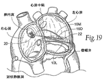
図19は、直接中間移植物10D、内側曲線移植物10M、及び直接外側移植物10Lを備えるシステム22を示す。移植物10のうちの1つ、2つ、又は全ては、先述の通り、弁に対して平行であるか、又は上へ向かってアーチ状となっているか、又は下へ向かって曲がっていることができる。
FIG. 19 shows a
(B.アンカーエレメント)
(1.大心臓静脈内)
先に説明したように、後部組織アンカー領域14は、望ましくは、左心房内の弁輪上側の組織にそのしっかりとした足掛かりを増大させるために、大心臓静脈内に配置される1以上の後部アンカー18を含む。
(B. Anchor element)
(1. Intravenous heart)
As previously described, the posterior
後部アンカー18は様々に構築し得る。アンカー18は、剛性、又は可撓性、又は弾性、又は展性、又は固体、又は多孔性であってもよい。アンカー18は、局在化されたアンカー部位を提供するような大きさ及び構成を取り得るし、又は、血管の高さの心房組織とより連結させるために、血管の長さに沿って、意図されるアンカー部位から内側及び外側に延在及び拡張され得る。
The
図20に示されるように、アンカー18は、例えば、右心房内の冠状静脈洞を通じて、大心臓静脈内に導入するような大きさ及び構成にされたステント様構造物24を含むことができる(より詳細には後述する)。構造物24は、自己拡張ステント又は、内部の力によって拡張される展性構造物、例えば、バルーン、の形態を取り得る拡張可能な足場を含むことができる。構造物24は、可撓性、又は半剛性、又は剛性であることができ、或いは、異なる機械的特性の領域を有することができる。
As shown in FIG. 20, the
或いは、アンカー18は、大心臓静脈内へ進行させるような大きさ及び構成にされている、予め形成された、非拡張性の中空チューブ又は予め決められた形態の固体棒状物を含むことができる。さらに或いは、アンカー18は、所望の機械的特性を有するために調整し得る、血管内に注入される不活性な生体適合膨張性材料を含むことができる。或いは、アンカー18は、所望の機械的特性を有するために調整し得る、少なくとも部分的に生体適合性材料が充填された中空状構造物を含むことができる。
Alternatively, the
特定の配置にかかわらず、冠状静脈洞の支流内に位置する場合、アンカー18は、望ましくは、放射線不透過性であるか、又は、X線透視による視覚化を容易にするために放射線不透過特性が取り入れられる。
Regardless of the particular arrangement, when located within a tributary of the coronary sinus, the
図21に示されるように、アンカー18は、例えば、返し(barb)、歯(tine)等によって周囲の血管壁をつかむことにより、血管内の位置に保持されてもよい。所望であれば、アンカー18は、縫合、接着剤、又は血管内の同様の物質によってさらに固定されてもよい。アンカー18は、粗い又は穴の開いた表面を取り込ませることができ、且つ/又は、組織中への伸長を促進するためにその他の物質(例えば、ポリエステル繊維、刺激物質、又は薬物)をコーティング又は注入することができる。アンカー領域14が使用される場合、大心臓静脈内及び周辺において、線維形成を促進し、組織裂開の確立を潜在的に減少させるために、アンカー18は、アンカー領域14に先立ち、数週間、大心臓静脈内に配置させてもよい。この週の数は変化し得るが、大半の患者は、最低限として4週間、何らかの治療が行われることが期待され得る。この配置では(図22及び23参照)、後部アンカー領域14は、血管の外側の左心房内で操作されるため、及び、血管内に位置するアンカー18中に固定されるか又はしっかりとした足掛かりを獲得するための、大きさ及び構成にされている。例えば、後部アンカー領域14は、血管の外側から、血管内部に位置するアンカー18材料又は構造物中へと固定する、フック又はT型の構造物を含むことができる。或いは、図10Aに示されるように、一体化されたTのクロスアームが、大心臓静脈の十分な長さに沿って、冠静脈系内部に到達する程度まで延ばされた場合、このクロスアーム自体が、別々に展開された構造物とのアンカー18として機能し得る。或いは、後部アンカー領域14(又は、そのことについては、移植物10全体)は、血管内に位置するアンカー18材料又は構造物を通じて血管の外側から糸が通される、縫合材料を含むことができる。
As shown in FIG. 21, the
(2.繊維性中隔組織への固定)
前部アンカー領域16は、中隔を貫通し、右心房内へ突出するような大きさ及び構成にされている。その場所において、前部アンカー20は、前部アンカー領域16を捕捉し、右心房内の中隔の繊維性且つ周辺にある筋肉組織に対してアンカー領域16を保持する。
(2. Fixation to fibrous septal tissue)
The
前部アンカー20は様々に構築し得る。図示された実施形態において(例えば、図10、22、及び23参照)、前部アンカー20は、前部アンカー領域に固定されるアンカーボタンという形態、噛み合い、及び機能を採る。アンカーボタン20は、中隔に対して固定する、返しの付いたステイ25を含む。ステイ25は、橋渡し領域、すなわち、左心房内のブリッジエレメント12に及ぶ所望の程度の張力を維持させるために、前部アンカー領域16に圧着させることができる。アンカーボタン22は、中隔の右心房側、又は中隔の左心房側及び右心房側の両方上にのみ配置し得る。
The
或いは、前部アンカー領域16(又は、そのことについては、移植物10全体)は、アンカーボタン等の使用の有無に関わらず、中隔の繊維性の壁を通じて糸が通される、縫合材料を含むことができる。後者の場合、より近位の静脈アンカーは、アンカーとして心房中隔を使用する必要性に取って代わり得る。 Alternatively, the anterior anchor region 16 (or, for that matter, the entire implant 10) can be made of suture material that is threaded through the septal fibrous wall with or without the use of anchor buttons or the like. Can be included. In the latter case, a more proximal venous anchor may replace the need to use the atrial septum as an anchor.
後述するように、アンカー部位は、中隔に対する代わりに、SVC又はIVCのいずれかの内部であり得る。 As described below, the anchor site can be inside either SVC or IVC instead of to the septum.
(C.移植)
移植物10又は移植物システム22は、直前に記述した通り、心臓弁輪内への移植に対して様々に役立つ。移植物10又は移植物システム22は、例えば、開心術手法において移植し得る。或いは、移植物10又は移植物システム22は、画像誘導下、末梢血管接近部位を介する、例えば、大腿部又は頸部の静脈又は大腿動脈を介する(IVC又はSVCを介する)カテーテルに基づく技法、又は、画像誘導下、左心房から大動脈への経動脈逆行アプローチを用いて移植することができる。
(C. transplantation)
或いは、移植物10又は移植物システム22は、胸腔鏡手段を用いて胸から、又は、その他の外科的接近手段によって右心房を通じて、画像誘導下で、移植し得る。
Alternatively, the
画像誘導としては、限定されるものではないが、X線透視、超音波、磁気共鳴、コンピューター断層撮影、又はこれらの組み合わせを挙げることができる。 Image guidance includes, but is not limited to, fluoroscopy, ultrasound, magnetic resonance, computed tomography, or a combination thereof.
図24〜30は、画像誘導下での経皮、カテーテルに基づく手順による、図10に示されるタイプの移植物10の展開の典型的な実施形態を示す。
FIGS. 24-30 show an exemplary embodiment of deployment of an
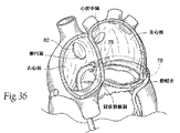
経皮による血管への接近は、大腿部又は頸部の血管内への従来法により達成される。図24に示されるように、画像誘導下、第1カテーテル26は、血管系を通じて右心房内へと導かれる。冠状静脈洞を通じて後部アンカー18を大心臓静脈内へと展開することが第1カテーテル26の役割である。冠状静脈洞へのカテーテルの接近は、大腿動脈からIVC又はSVCへの経路(後者の場合、大静脈ブレース用)又は、上肢若しくは頸部の静脈からIVC又はSVCへの経路(後者の場合、大静脈ブレース用)のいずれかによって達成され得る。SVCの場合、最短の接近方法は、上肢又は頸部血管系上部からであるが、IVCでも、SVC及び右心房を通過することにより接近し得る。同様に、IVCへの最短の接近方法は大腿静脈を通じるものであるが、SVCでも、IVC及び右心房を通過することにより接近し得る。図24〜30は、図示する目的のため、SVC経路を通じた接近を示す。後述する移植技法においては(図36〜39参照)、IVC経路を通じた接近が、図示する目的のために示されている。
Percutaneous access to the blood vessels is achieved by conventional methods into the femoral or cervical blood vessels. As shown in FIG. 24, the
第1カテーテル26は、例えば、右心房内の冠状静脈洞を通って、僧帽弁の後部輪の上側且つ並行している大心臓静脈内へ、アンカー18を進行させる。ガイドワイヤー(示されておらず)を、進行を導くために使用してもよい。アンカー18は、移植物10の後部アンカー領域14に対する所望の固定部位を提供するために十分な長さまで伸長される。後部アンカーの長さは、冠静脈系内にある場合には、20mm〜200mmの範囲に及び得る。後部アンカー18の所望の位置は、例えば、それ自体の拡張又は血管内での拡張を引き起こすためのバルーンの使用によって確保することができ、すなわち、輸送カテーテル内での形状からの構造的変化を必用としなくてもよい。
The
図25に示されるように、血管内に後部アンカー18の位置が確保された場合に、第1カテーテル26は回収され(ガイドワイヤーは、使用する場合には、冠状静脈内の後部アンカー18内に放置し得る)、第2カテーテル28は血管系から右心房内へと導かれる。第2カテーテル28は、中隔へ固定する前部アンカー20を担持する。第2カテーテル28は、右心房と左心房との間の中隔を貫通するために展開される先端針(示されず)も担持する。図25においては、この針は、卵円窩をその下縁近くにおいて貫通している。横切るための安全な構造物を構成し、従来の血管内技法により容易に接近し得る解剖学的指標を有し、中隔を通じて右心房から左心房への接近を行う目的のための穴が開いていることから、卵円窩は選択される。カテーテルによる卵円窩への接近は、大腿−IVC又は内頸−SVC経路のいずれかにより達成し得る(大腿−SVC経路は図示する目的のために単純に示されている)。図25に示されるように、一旦、右心房と左心房との間のアクセスが開通すれば、ガイドワイヤー32は、針状のカテーテル28を通じて左心房内へ経中隔的に進行する。
As shown in FIG. 25, when the position of the
第2カテーテル28は回収される(図26Aではそれが存在しないことが示されている)。画像誘導下、移植物送達カテーテル34は、卵円窩開口部を通じて(そこに結合している、既に送達されているアンカー20を通じて)経中隔的に左心房へとガイドワイヤー32上を進行する。或いは、移植物送達カテーテル34は、右心房へ通じる外科的接近手段により経中隔的に展開することができる。
The
画像誘導下、移植物送達カテーテル34は、大心臓静脈内に存在する後部アンカー18と同じ高さの標的とする後部アンカー部位に方向付けられる。移植物送達カテーテル34は、画像誘導を用いてカテーテル34を目的とする部位へ方向付けるための、搭載された遠隔操作メカニズムを含むことができる。或いは、又は組み合わせて(図26B参照)、大心臓静脈内に位置するアンカー18は、(アンカー18の一部又は必用とされる磁力を一時的に供給する、別に送達されたカテーテル内のいずれかとして)標的とするアンカー部位と同一の空間を占めるその長さに沿って1以上の磁気エレメント210を有することができる。この配置では、移植物送達カテーテル34の遠位端は、大心臓静脈内の目的とするアンカー部位において磁気エレメントに磁気的に引き付けられる磁気エレメント212又は軟質強磁性体を含むことができる。
Under image guidance, the
一旦、移植物送達カテーテル34が、標的とするアンカー部位に配置されたならば(図27A参照)、移植物送達カテーテル34は、アンカー部位にある心房組織から大冠状静脈にかけて開口させるために、画像、磁気誘導カテーテル又は本発明に記載されるその他の手段又は標準的インターベンショナル若しくは外科的行為によって操作される。移植物10の後部アンカー領域14は、(図27Bに示されるように)そこに位置する後部アンカー18と結合させるために、移植物送達カテーテル34から大心臓静脈内へと進行し、(図27Cに示されるように)この場合にはフックによる結合固定メカニズムが図示されている。或いは、アンカー領域14は、結合するために、組織を通じて、又、大心臓静脈内の後部アンカー18の支柱内部と、捕捉するグラスパーを含むことができる。
Once the
図28に示されるように、一旦、後部アンカー領域14と後部アンカー18との間の結合が形成されたならば、移植物送達カテーテル34は、大心臓静脈の外へ、左心房の前部を横切って引き抜かれる。橋渡し領域、すなわち、移植物10のブリッジエレメント12は、それによって、左心房内のカテーテル34から展開される。このように、前部アンカー領域16は、中隔を通じて右心房へと逆方向に導かれる。
As shown in FIG. 28, once the bond between the
移植物送達カテーテル34は、橋渡し領域、すなわち、ブリッジエレメント12を、所望の量の張力が及ぶ状態に配置するために、すでに結合している前部アンカー領域16を通じてそれを右心房内から滑り込ませる場合、橋渡しエレメント、すなわち、ブリッジエレメント12に引っ張り力を及ぼし得ることを図29は示す。或いは、前部アンカー領域16は移植物送達カテーテル34から解放することができ、適当な捕捉器具(例えば、7フレンチのグラスパー)は、所望の量の張力が及ぶ状態に配置するため、右心房内のアンカー領域16に保持させるように橋渡し領域12を右心房内に展開することができるのに対し、前部アンカー領域16は、適当な張力を得るために、ガイドカテーテルにより前方へ滑り込まれる。橋渡しエレメント12に張力が及んだ状態に展開するために、様々なその他の外科的技法及び操作を使用することができる。例えば、前部アンカー16は、切断ツールによって切断し得るシンチ開放メカニズム、及び、橋渡し、すなわち、ブリッジエレメント12の末端ワイヤーコンポーネントで糸を通された別のアンカーを含むことができる。調整が終了した時点で、後者は切断される。
The
手術操作及び/又は使用する装置にかかわらず、(移植物送達カテーテル34又は別の捕捉ツールのいずれかによって右心房内から)前部アンカー領域16を左心房に向かって内側に引っ張ることは、後部アンカー領域14が後部アンカー18に結合している領域内の後部心房組織に引っ張り力を及ぼす。引っ張り力は、後部心房組織を、左心房の前部心房組織に向かって内側に引き付ける。細長い後部アンカー18の存在が、大心臓静脈の長さを連結するために機能することにより、引っ張り力を外側及び内側に分布させる。引っ張り力は弁輪を短軸に沿って短縮させるように機能し得る。大心臓静脈内におけるアンカー18の存在は、一体化された物理的構造物へと大心臓静脈の長さを連結し、少なくとも一点で引っ張った場合、後部輪全体を圧縮するように機能する。
Regardless of the surgical procedure and / or the device used, pulling the
移植物12に張力が徐々に働く場合、医師は、僧帽弁逆流の発生をモニターするために、様々な従来方法を、例えば、コントラスト心室法を又は心エコードップラー検査を、選ぶことができる。医師がこの方法を選択した場合、医師は、僧帽弁逆流発生の所望される減少又は消滅を達成するために、移植物12に及ぶ張力を動的に調整することができる。
When tension is applied to the
図29に示されるように、一旦、移植物12が満足し得るように配置され且つ/又は所望の治療的結果が達成されたならば、前部アンカー領域16をアンカーボタン20に強く保持させるために、医師は、クリップ38を圧着させるツール36又は前部アンカー領域16と機能的に同等のメカニズムを導入する。或いは、前部アンカー領域16はネジ式にすることができ、所望の程度の張力状態で前部アンカーエレメント16が保持されるように、領域16にナットを送達してネジ込むことができる。図30に示されるように、前部アンカー領域16はクリップ38(又はナット)の隣で切断され、設置は終了し、血管内のツール又は複数のツールは回収される。
As shown in FIG. 29, once the
前部アンカー領域16の右心房内への突起は、必要又は所望の場合に、移植物12の再配置、再緊張化、及び/又は右心房からの回収を容易にする。
The protrusion of the
(II.僧帽弁輪の負荷除去を達成するための移植物システム)
(A.システム概観)
直線状又は線状のブリッジエレメントをまさに伴って記載される中隔横断の実施形態は、僧帽弁輪上方の後部領域から、同様に僧帽弁輪上方の前部中隔組織領域へと原則的に左心房を横切る(すなわち、水平方向に対し上向きに約15°〜45°未満のベクトルにおける)、主要な力ベクトルを適用する。この目的のための移植物10又は移植物システム22の使用は、僧帽弁逆流の顕著な適合を提供し得る。
(II. Implant system for achieving mitral valve unloading)
(A. System overview)
The transseptal embodiment described with just a straight or linear bridge element is in principle from the posterior region above the mitral annulus to the anterior septal tissue region also above the mitral annulus. The main force vector is applied across the left atrium (i.e. in a vector of about 15 ° to less than 45 ° upwards relative to the horizontal direction). Use of the
図31は、僧帽弁輪領域の組織における水平方向の力ベクトル、上方又は上向きの吊り上げ力ベクトル(すなわち、水平方向の上方に約45°より大きいベクトルにおいて)のいずれか単独又は組み合わせを適用する、僧帽弁逆流処置のための移植物システム40を示す。上向きの吊り上げ力は、左心臓の後部僧帽弁輪から右心臓の移植物及びブレースシステムへの僧帽弁輪における張力を緩めるか又は消失させる。それはまた、大心臓静脈と左心室との間の心房組織上に、より直接的な垂直方向の力ベクトルコンポーネントを与え、水平方向の力ベクトルの適用は、より直接的に、輪部に対して所望の圧縮性の効果を導く。大心臓静脈と心室との間の心房組織に垂直方向の力を適用することにより、輪部に対して直接的に適用される前に必要とされる大心臓静脈における水平方向内側への動きは、より少ないものとなる。
FIG. 31 applies either alone or in combination a horizontal force vector in the tissue of the mitral annulus region, an upward or upward lifting force vector (ie, in a vector above about 45 ° horizontally upward). FIG. 3 shows an
僧帽弁輪における張力は、左心室及び輪部が拡張される場合に上昇し得る。輪部における張力の強度は、機能的な僧帽弁逆流、特に少なくとも等級2+の機能的な僧帽弁逆流を含む状況において、顕著であり得る。輪部が張力下にある場合、僧帽弁索はぴんと張られ、下方の及び互いに離れた接合点を引っ張る。また、輪部と弁尖との結合は緊張したものとなる。例えれば、正中線の支柱(輪部)が、テントを地面(乳頭筋)へとピンと張って保持している(緊張した弁尖)ロープ及び杭(索)を有した2葉のテント(弁尖)を支え上げている。収縮期において接合させるための十分な弁尖組織が存在しない場合には、機能的な僧帽弁逆流がその結果である。膨張が輪部において起き、心室の壁面を引き離すのと同調して働くことは張力の結果であると信じられている。 Tension in the mitral annulus can increase when the left ventricle and annulus are dilated. The strength of tension in the annulus can be significant in situations involving functional mitral regurgitation, particularly at least grade 2+ functional mitral regurgitation. When the annulus is under tension, the mitral chord is taut and pulls the junctions below and away from each other. Moreover, the connection between the ring part and the leaflet becomes tense. For example, a two-leaf tent (valve) with a rope and stakes (tensioned leaflets) holding the tent pinched to the ground (papillary muscles), with a midline strut (ring) Supports the cusp. If there is not enough leaflet tissue to join during systole, functional mitral regurgitation is the result. It is believed that expansion occurs in the annulus and works in synchrony with pulling apart the walls of the ventricles as a result of tension.
移植物システム40は、心房構造物において上方に引っ張り上げることにより、輪部(心室構造物)における吊り上げ力ベクトルを与える。この結果を達成するために、システム40は組織連結コンポーネント42Aを含み、これが大心臓静脈を、一体化された物理的構造物へと、その長さに沿って連結する。システム490はまた、大心臓静脈と心室との間の領域において大心臓静脈を心室へと連結又は結合するための結合手段42Bを含む。このように、システム40が連結された大心臓静脈(心房構造物)上で上方向に引っ張る場合、吊り上げ力ベクトルは、心室上のその結合された大血管−心室組織領域によって移動される。
The
より詳しくは、図31に示される移植物システム40は、組織連結コンポーネント42Aを備える。組織連結コンポーネント42Aは、大心臓静脈の長さに沿った1以上の点において適用される吊り上げ力が、大心臓静脈全体をその長さに沿って吊り上げるために働くように、その大心臓静脈を、一体化された物理的構造物へと、その長さに沿って連結する。図31に示される実施形態において、組織連結コンポーネント42Aは、ほとんどの部分が大心臓静脈中に存在する。それは、先に記述された後部アンカー18と同じような大きさ及び構成にされる。組織連結コンポーネント42はまた、大心臓静脈中で、すでに記述されたものと同様の様式で導入され、安定化され得る。
More particularly, the
図31に示されるように、組織連結コンポーネント42Aは、望ましくは環様であり、大心臓静脈内の後部僧帽弁輪の長さにおける大部分に隣接して大心臓静脈から冠状静脈洞へと拡張している。例えば、組織連結コンポーネント42Aは、心室筋肉の上方、5mm〜20mm程度に位置する。組織連結コンポーネント42Aは、望ましくはX線透視による視覚化を促進するための、放射線不透化性の特徴を有する。
As shown in FIG. 31, the
結合手段42Bは、大心臓静脈及び心室間の領域において大心臓静脈を心室へと連結又は結合する。この手段42Bは、非線維性の、大心臓静脈の位置及び下方の薄い心房組織を僧帽弁輪へと結合する。この手段42Bは、実際には、コンポーネント42に対し適用される吊り上げ及び水平方向の力が、輪部それ自体の吊り上げ及び/又は圧縮へと直接的に移動されるように、大心臓静脈を左心室筋肉基底隣接部へと連結するコンポーネント42Aを、後部僧帽弁輪へと結合させる。手段42Bはまた、コンポーネント42に対し長期にわたり適用される力の結果として、大心臓静脈及び左心室頂部間におけるタイプ1の左心室分断が起きる可能性を減少させる。
The coupling means 42B couples or couples the large heart vein to the ventricle in the region between the large heart vein and the ventricle. This means 42B joins the non-fibrous, large cardiac vein location and the underlying thin atrial tissue to the mitral annulus. This means 42B actually leaves the great heart vein so that the lifting and horizontal forces applied to the component 42 are moved directly to lifting and / or compression of the annulus itself. A
大心臓静脈を心室へと結合させるための手段42Bは、多様な形態を取り得る。ステープル等の機械的な手段は、コンポーネント42A及び左心室における組織間に取り付けることができる。薬物及び/又は刺激物質、及び/又は熱(例えば、高周波加熱)、及び/又は化学物質を、この領域へと適用してもよい。あるいは、又は組み合わせて、大心臓静脈の位置又は近傍の組織を、組織を強化してコンポーネント42Aの貫通口を持ち上げるための線維形成に供することができる。線維形成は、ポリエステルコーティング、薬物、刺激物質溶離、又はそれらの組み合わせの使用を伴い得る。線維形成はまた、熱の適用によっても達成され得る。
The means 42B for coupling the great heart vein to the ventricle can take a variety of forms. Mechanical means such as staples can be attached between the
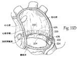
図33Dに示されるように、あるいは上述のものと組み合わせて、手段42Bは、組織連結コンポーネント42Aにより担持される磁石アレイ220、及び後部輪の下方に外科的に配置される磁石アレイ又は軟質強磁性体エレメント222を備えることができる。磁石220の極性は、磁性体又は軟質強磁性体エレメント222を磁気的に引き付けるために選択される。もちろん、このエレメント222が磁石であった場合には、軟質強磁性体を磁石220の代わりに大心臓静脈内で使用することができる。
As shown in FIG. 33D, or in combination with the above, the
図示された実施形態において、エレメント222は、例えばバルーン等の拡張可能な又は膨張可能な物体224によって移植のために保持される。この物体224は、大動脈弁を通じて左心室へ、後尖の下方に離れて配置された位置へと、カテーテルの展開によって個々に配置される。一旦移植されると、エレメント222の配置を安定化するために、物体244は拡張され、又は例えば生理食塩水の注入によって膨らまされる。磁石220とエレメント222との間の磁性的な引き付けが2つの組織領域をひとつに引き合わせ、それによって大心臓静脈を後部輪へと結合させる。
In the illustrated embodiment,
図31に示されるように、システム40はまた、1以上のリフティングコンポーネント44を備える。リフティングコンポーネント44は、大心臓静脈内に存在する組織連結コンポーネント42A内に結合する、左心房内の後部アンカー領域46を有する。望ましくは、少なくとも1つのリフティングコンポーネント44は、図31に示すような、僧帽弁輪の上方で、かつ僧帽弁輪のほぼ中心部に配列した組織補強エレメント42Aに結合した後部アンカー領域46を有する。図32に示すように、その他の吊り上げエレメント44は、後部輪の内側及び/又は外側面上の、1つ又は両方の三角部の位置又は近傍で展開され得る。
As shown in FIG. 31, the
図31及び32に示すように、リフティングコンポーネント44の少なくとも1つは、組織連結コンポーネント42Aを伴うその固定点から上方向に、左心房の天井部へと向かう、左心房内に拡張するために前もって形成又はさもなければ構成される橋渡し領域又はブリッジエレメント48を有する。
As shown in FIGS. 31 and 32, at least one of the lifting
このリフティングコンポーネント44はまた、左心房の外部を通り、高い隔壁を有する線維性の組織を通じて右心房へと通じる。図31及び32において、前部アンカー領域50は、卵円窩の上方周縁の位置又は近傍に固定されて示される。より詳細は後述されるが(図33B及び33Cに示すように)、リフティングコンポーネント44の前部領域はSVC又はIVC内に固定され又は繋がれることができ、そして隔壁それ自体には固定されない。この配置において(図33B参照)、高い心房ブリッジエレメント48を伴うリフティングコンポーネント44は、中隔組織への固定なしに卵円窩における高い位置の隔壁を通過することができ、またSVCにおけるステントの代わりに固定されあるいは繋がれる。この配置は吊り上げベクトルの効果を最大化するものと信じられている。別の方法においては(図33C参照)、リフティングコンポーネント44(望ましくは高い心房ブリッジエレメント48を伴わない)は、中隔組織への固定なしに卵円窩における低い位置の隔壁を通過することができ、またSVCにおけるステントの代わりに固定されあるいは繋がれる。
This
リフティングコンポーネント44は、屈曲、成型、結合、機械加工、モールディング、又は金属製又はポリマー性ワイヤー形成構造物の押出し成型によって形成することができ、可撓性又は剛性の、又は非弾性もしくは弾性の機械的特性を有し得る。このリフティングコンポーネント44は、様々な形状をとることができ、多様な幾何学断面を有し得る。リフティングコンポーネントは、例えば、通常、曲線をなす(すなわち円形又は卵型の)断面を有し得、あるいは通常、直線状の断面(すなわち、正方形又は長方形の)、又はそれらの組み合わせを有し得る。
The
望ましくは、リフティングコンポーネント44は「弾性」を有する。このリフティングコンポーネント44は、正常な、過負荷状態でない形状又は状態を有するような大きさ及び構成にされ、そこにおいてこのコンポーネントは、圧縮された状態又は張力が及んだ状態とはなっていない。リフティングコンポーネント44の素材は、所望のバネ定数を有するように選択される。バネ定数は、コンポーネント44に対して、後部アンカー領域46が組織連結コンポーネント42Aへと結合する場合に前部アンカー領域50において適用される外部の牽引への応答において、弾性的に伸長し、張力状態で配置されるための能力を与える。張力が及んだ状態においては、このリフティングコンポーネント44は、組織連結コンポーネント42A上に上向きの力(例えば、水平方向上向きに約45°を超える力ベクトル)を適用する。
Desirably, the
システム40は、リフティングコンポーネント44は、右心臓中でリフティングコンポーネント44の前部アンカー領域50へと結合されるような大きさ及び構成にされたアンカー52をさらに備える。アンカー52は、右心房中の隔壁に対して張力状態で保持される。別の実施形態においては、IVC又はSVCにおけるステント又は相当する非妨害アンカーが、リフティングコンポーネント又はコンポーネント44のためのアンカー部位として働く。
The
リフティングコンポーネント及び固定コンポーネントは、望ましくはX線透視による視覚化を促進するための放射線不透過性の特徴を有する。 The lifting component and the fixation component desirably have radiopaque features to facilitate visualization through fluoroscopy.
図32に示すように、システム40は1以上のリフティングコンポーネント44を含み得る。複数のリフティングコンポーネント44は、連結コンポーネント42Aに沿って間をおいて配置された位置に結合することができ、例えばそれは、中部後部輪の位置又は近傍、及び外側及び内側三角部に結合された3つのリフティングコンポーネント44である。リフティングコンポーネント44の前部アンカー領域50は、右心房へ通じる高い心房中隔における卵円窩上方周縁の位置又は近傍における、単独の開口部を通じて通過することができ、そこで単独のアンカー32により結合され、保持される.
連結された大心臓静脈を垂直方向に持ち上げる曲線的なリフティングコンポーネント44は、それを隔壁に向かって水平方向内側に移動させる間、左心房チャンバの壁面に対する壁面支持体を提供する。
As shown in FIG. 32, the
A
図31〜33に示されるやり方で組み立てられる場合、システム40のコンポーネントは、輪部を拡張しようとする壁面張力をいくらか消失させることを通じて、後期心臓拡張期及び早期収縮期における僧帽弁輪からの張力を劇的に弱める。連結コンポーネント42によって強化されまた連結された大心臓静脈は、それによりバネ様のリフティングコンポーネント44又はコンポーネントが心室の筋肉壁面張力を消失させ、また、連結された房室溝を通じてそれを中継することにより、左心室におけるベース過負荷が劇的に消失するレバーとなる。
When assembled in the manner shown in FIGS. 31-33, the components of the
心室が血液で満たされ始める場合、このバネ様のリフティングコンポーネント44又はコンポーネントは、僧帽弁領域が最も小さくなり、機能的な僧帽弁逆流が最も起こりやすい場合に、拡張終期において及び前期収縮において最大限に負荷をかけられた状態となる。バネのエネルギーは、拡張終期及び前期収縮における心室筋肉の壁面張力の過負荷を取り除き、輪部は、ぴんと張られた僧帽弁弁尖からの張力を解除又は消失させるのに十分な程度に張力を(少なくとも部分的に)緩められ、それによって、特に、後期拡張及び前期収縮において閉鎖を可能にするための改善された僧帽弁弁尖の再接近を可能にする。
When the ventricle begins to fill with blood, this spring-
システム40はまた、1次的又は2次的な効果としての輪部の変形をもたらす。
The
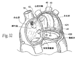
図34に示すように、システム40は、短軸を短くするために輪部の短軸を横切って、又は主軸を短くするために輪部の主軸を横切ってのいずれかで拡張する、又は短軸及び主軸の両方を同時的に処置することができる、補助的な移植物コンポーネント60を含み得る。このような移植物コンポーネント60は、実際に、それらをシステム40における力の解除、及び輪部を変形させるための、輪部の短軸、主軸、又は両方の軸に沿った1以上の直接的な機械的な力と組み合わせて適用するような大きさ及び形状にすることができる。システム40によって与えられる吊り上げ力は、大心臓静脈中のアンカーに対し適用される力によって後部輪に与えられる任意の圧縮効果を達成するために動かされる必要がある、大心臓静脈と心室との間の心房組織における水平方向のリード長を減少させる。従って、補助的なコンポーネント又はコンポーネント60により与えられる、後部から前部への力ベクトル及び/又は内側から外側への力ベクトルは、所望の結果を達成するために連結して作動させることができる。
As shown in FIG. 34, the
補助的なコンポーネント又はコンポーネント60の変形効果は、それにより、システム40によって与えられる輪部の吊り上げ力の存在下で増幅される。
The deformation effect of the auxiliary component or
補助的な移植物コンポーネント60は、例えば屈曲、成型、結合、機械加工、モールディング、又は押出し成型等によって、好適にコーティングされ、含浸され、又はさもなければ生体適合性を有するための物質によって処理され、あるいはそのような素材の組み合わせである、生体適合性を有する金属性素材又はポリマー素材から作ることができる。素材はまた、X線透視による視覚化を促進するために、望ましくは放射線不透過性であり又は放射線不透過性の特徴を有する。補助的な移植物コンポーネントは、望ましくは、輪部の上方組織に係合する支柱を含む。
The
補助的な移植物コンポーネント60に使用され得る移植物のさらなる詳細は、2003年10月1日に提出された、標題「心臓弁輪を変形させるためのデバイス、システム、及び方法(Devices, Systems, and Methods for Reshaping A Heart Valve Annulus)」の継続中の米国特許出願10/677,104号において示され、参照により本明細書中に組み入れるものとする。
Further details of implants that may be used for the
(B.移植)
まさに記述されたように、移植物システム40は、様々なやり方での左及び右心臓における移植のために、それら自身が役立つ。このシステムは、例えば、心臓切開外科手術等において移植することができる。あるいは、このシステムは、カテーテルをベースとした手法を用いて、大腿部、頸部、鎖骨下の静脈、又は画像誘導下での大腿動脈等の、周辺静脈における接近部位を経由して移植することができる。図24〜30は、画像誘導下での、経皮的な、カテーテルをベースとした手順の代表的な実施形態がシステム40を移植可能であることを示す。
(B. Transplant)
As just described, the
あるいは、システム40は、これも画像下で、胸部を通じた胸腔鏡的な手段、又は右心房を通過するその他の外科的な接近手段を使用して移植することができる。画像誘導は、限定されるものではないが、X線透過、超音波、磁気共鳴、コンピューター断層撮影又はそれらの組み合わせを含む。
Alternatively, the
上述のような移植物システム40を、なんらかの顕著な程度までに適合し得る等級1+を超えて等級4+までを含む機能的な僧帽弁逆流に対し弁尖の接合を可能にさせるような大きさ及び構成にし得ることが確信されている。このシステムは迅速な展開、容易な血管内輸送、及び十分な心房内の回収可能性を提供する。システムはまた、強いX線透過のための指標を提供する。
Large enough to allow the
(III.右心臓のブレース)
図33Aに示すように、例えば図31〜32に示されるシステム40又は図10〜19に示される移植物10等の、左心房内に展開される中隔横断コンポーネントを有する任意の心房内システムはまた、組織連結コンポーネント18又は42に対する中隔アンカー20又は52を安定化するためのブレースとして働く右心臓コンポーネント54を含み得る。図33B及び33Cに示すように、例えば図31〜32に示されるシステム40又は図10〜19に示される移植物10等の、左心房内に展開される中隔横断コンポーネントを有する任意の心房内システムはまた、SVC又はIVC内に又はそれらに対して繋がれて配置され、組織連結コンポーネントに対する心房内コンポーネントを固定する右心臓コンポーネント54を含み得る。
(III. Brace of the right heart)
As shown in FIG. 33A, any intra-atrial system having a transseptal component deployed in the left atrium, such as the
(A.右心房中隔ブレース)
図33Aに示される実施形態において、右心臓コンポーネント54は、中隔アンカー52へと結合された隔壁ブレースバー56を含む。図示されたように、このブレースバー56は、望ましくは、力を均一的に隔壁に沿って分布させるために、アンカー52から隔壁に沿って上方及び下方に拡張する。図33Aに示されるタイプのブレースバー56は、図10に示される移植物10と組み合わせて使用される場合、アンカー20に対してと同様の様式で結合され得る。
(A. Right atrial septal brace)
In the embodiment shown in FIG. 33A, the
図33Aにまた示されるように、右心臓コンポーネント54は、通常、下大静脈(IVC)、上大静脈(SVC)又は冠状静脈洞(CS)又は右心房中のいずれかに配置され、ブレースバー56へと結合したステント58を含み得る。右心臓ステント58は、リフティングコンポーネントから右心臓への力をさらに分散させ吸収させるためのブレースとして働く。
As also shown in FIG. 33A, the
(B.大静脈の固定)
図33B及び33Cに示すように、所定の心房内ブリッジコンポーネント(例えば、図10における移植物10又は図31におけるコンポーネント44等)は、SVC又はIVCのいずれかにおいて展開されるアンカー又はステント58へと結合されあるいは直接的に繋がれ得る。この配置において心房内ブリッジコンポーネントは隔壁へと固定されず、むしろ隔壁を通じて(例えば卵円窩において)直接的に固定ステント58へと通じる。ワッシャー200は、隔壁を引き裂くことなくブリッジコンポーネントを通過させることを可能にするが、コンポーネントを固定はしない隔壁上で提供され得る。代わりに、例えばケーブル又は形状記憶合金又はつなぎ鋼202等のエレメント202が、ブリッジコンポーネントを、このブリッジコンポーネントを固定するために働くステント58に結合する。
(B. Vena cava fixation)
As shown in FIGS. 33B and 33C, a given intra-atrial bridge component (eg,
図33Bに示される実施形態において、ワッシャー200は卵円窩の高い位置に位置し、エレメント202はSVC中のステント58に結合される。この配置が、大心臓静脈中の組織連結コンポーネント42上でブリッジコンポーネントBCにより生じる上方への吊り上げ(垂直方向の)ベクトルを最大化すると信じられている。
In the embodiment shown in FIG. 33B, the
図33Cに示される実施形態において、ワッシャー200は卵円窩の低い位置に位置し、エレメント202はSVC中のステント58に結合される。この配置が、大心臓静脈中の組織連結コンポーネント42上でブリッジコンポーネントBCにより生じる水平方向のベクトルを最大化すると信じられている。
In the embodiment shown in FIG. 33C, the
(C.移植)
上述の右心臓コンポーネント54は、先に記述された任意のやり方で移植を行うためにそれ自身役立つ。
(C. transplantation)
The
カテーテルをベースとした代表的な実施形態において、組織連結コンポーネント42(例えば、直径10mm〜25mmに拡張された、剛性の、可塑性を有する、放射線不透過性の指標を有するステントを備えることができる)は、上述されたようにカテーテルによって大心臓静脈内へと配置される。ブレースステント58をIVC中に配置することを意図する場合、IVCへの大腿静脈経路が使用され得る。ブレースステント58をSVC中に配置することを意図する場合、IVCへの頸静脈経路が選択される。
In an exemplary catheter-based embodiment, tissue connection component 42 (e.g., can comprise a stent having a rigid, plastic, radiopaque index expanded to a diameter of 10-25 mm). Is placed into the great cardiac vein by a catheter as described above. If it is intended to place the
次いで、ガイド用の鞘(シース)が、大腿静脈−IVC−卵円窩経路を通じて左心房を横切り組織連結コンポーネント42へと配置される。エレメント202はこのガイド用の鞘を通じて通る。エレメント202はその遠位末端にグラスパー(例えば7フレンチの大きさの)を有する。グラスパーは、組織連結ステント42の支柱上をしっかりとつかみ、この捕捉を固定する。エレメント202は次いで卵円窩を通じ、左心房を横切る。左心房内へと引き上げるために、張力が右心房内から適用される。この張力は、可能な限り多くの機能的なMRを緩和又は消失させるために設定される。
A guiding sheath is then placed across the left atrium and into the tissue connection component 42 through the femoral vein-IVC-foveal fossa route.
大静脈ステント58(例えば、長さ5cm〜10cm、直径3cm〜7cmの寸法)は、エレメント202のためのカテーテルの接近が達成される大静脈へと、エレメント202上に装着される。IVC中で、例えば、ステント58は、ちょうど肝臓の上方かつ、ちょうど右心房の下方に配置される。固定デバイスは、その近接末端から大静脈ステント58まで、エレメント202上に装着される。エレメント202は、次いで固定ナットの下方で切断され、ナットの下方のエレメント202は除去される。ステント58は、エレメント202をその垂直方向の配置に保持し固定するために働く。
A vena cava stent 58 (e.g., a dimension of 5 cm to 10 cm in length and 3 cm to 7 cm in diameter) is mounted on the
ちょうど先に記述されたようなやり方で、心房隔壁、及び/又はIVC、及び/又はSVCのいずれかを潜在的なアンカー部位として使用する経路という選択肢を提供することは、遭遇する局所的な生体構造へ所定の移植物システムを柔軟に適合させること、ならびに心房内ブリッジコンポーネント又はコンポーネントにより適用されることが求められる力ベクトルの方向及び強度を最適に導き、また分配することを可能にすることが信じられている。 Providing the option of a route to use either the atrial septum and / or IVC and / or SVC as potential anchor sites in a manner just as described above would be Be able to flexibly adapt a given implant system to the structure and optimally derive and distribute the direction and strength of the force vector required to be applied by the intra-atrial bridge component or component It is believed.
(III.環状移植物システム)
(A.環状ループ)
(1.構造)
図35は、後部僧帽弁輪の領域における組織の上にかかり、単独又はその他の力ベクトル、環状ベクトルと組み合わせて適用される、僧帽弁逆流処置のためのループ状移植物システム70を示す。内側の放射状の力ベクトルが括約筋様の効果を有する後部輪を圧縮し、ならびに隔壁へ向かって膨張を軽減する。
(III. Annular implant system)
(A. Annular loop)
(1. Structure)
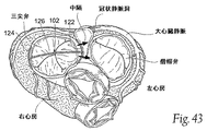
FIG. 35 shows a looped
図35に示されるように、システム70は、第1及び第2アンカー領域74及び76、及びそれらの間に存在する中間領域78を有する延在した移植物72を含む。全長において、移植物72は、ループとして展開されるような大きさ及び構成にされ、このものは(i)右心房又は大静脈中の心房中隔上の第1アンカー領域74から延長し、(ii)冠状静脈洞を通じて右心房内を通過し、そこから、中間領域78が、後部僧帽弁輪と平行に、かつその上方にある大心臓静脈内に存在し、(iii)ステント側壁又はT型のチューブ状デバイスの中央部を通じて大心臓静脈を出て、ステントの末端又はチューブ状アンカーデバイスの末端が大冠状血管の内部へと位置し、次いで外側三角における領域の位置又は近傍で、心房組織の隣接した内壁を通り抜け、(iv)そこから、後部から前部の方向で左心房を横切って、心房中隔を通じて右心房へと延長し、また(v)第2アンカー領域76を、第1アンカー領域74と同時に又は近くで、右心房中又は大静脈に固定できるようにさせる。1以上のアンカー80は、ループ移植物72を張力状態で保持する。
As shown in FIG. 35, the
図35に示すように、アンカー80のためのアンカー部位は前部僧帽弁輪平面の上方に示される。より詳しくは、アンカー80のためのアンカー部位は卵円窩内に存在する。これは、卵円窩が、比較的技術的に容易に、所定の従来の診療用放射性物質及び外科的スキル及び技術によって接近し固定され得る線維性の組織領域を有することによる。同様の技術的及び外科的な考慮事項を鑑みて、その他のより下方の又はより上方の部位が、隔壁におけるブリッジエレメントのベクトルを最適化するための通過における中隔横断点として使用され得ることが理解されるべきである。 As shown in FIG. 35, the anchor site for anchor 80 is shown above the anterior mitral annulus plane. More particularly, the anchor site for anchor 80 is in the foveal fossa. This is due to the fact that the foveal fossa has a fibrous tissue region that can be approached and fixed by certain conventional clinical radioactive materials and surgical skills and techniques, relatively technically easily. In view of similar technical and surgical considerations, other lower or higher sites can be used as the septal crossing point in the passage to optimize the vector of bridge elements in the septum. Should be understood.
ループ移植物70は、後部輪上に、放射状内側に引っ張る直接的な機械力を適用するために働く。この直接的な機械力は、輪部の短軸を短くするために働く。そうする中で、移植物70はまた、反動的にその主軸に沿って輪部を変形させ、及び/又は反動的にその他の周辺の解剖学的構造物を変形させる。しかし、移植物70の存在は、心臓弁輪に隣接した組織を安定化するために、特に、心周期における異なる且つ重要な時期において弁の接合が改善されるべき場合(例えば、後期拡張期及び初期収縮期)に、短軸又は主軸の長さに影響を及ぼすことなく役割を果たし得ることが理解されるべきである。移植物70により輪部に取り付けられた組織へと提供されるこの機械力は、心臓弁輪及び弁尖に、より正常な解剖学的形状及び張力を回復させ、心室収縮の間における弁尖の接合をもたらし得る。移植物70は従って、僧帽弁逆流の発生率を低下させる。
The
図示された実施形態における隔壁中のアンカー80の上方配置によって、ループ移植物70の機械力はまた、後部輪上において上方向(すなわち、垂直方向の力ベクトル)に引っ張る。固定が上大静脈中で起こる場合に、この垂直方向のベクトルはさらに促進され、より垂直方向の引っ張りが、中隔アンカーからであり得るよりもこの地点からであるブリッジエレメント又はブリッジ上で行われる。この垂直方向の力ベクトルはまた、輪部における張力を解除するために働き、ならびに、先に記述された有益な効果を伴って後部輪における任意の圧縮効果を達成するために、GCV中のアンカーによって移動される必要があるGCV及び心室間の心房組織における水平方向のリード長さを減少させるために働く。SVCオリフィスが十分に高い位置にある状況下では、右側のブリッジエレメントが、図33B中に示されるやり方で、中隔壁それ自体に対して固定される代わりにSVC中のステントに対し固定される場合、垂直方向のベクトルの強度は増強される。ループ移植物70はまた、図33Cに示されるやり方でIVC中のステントに対し固定することができ、選択状況においては、逆のものがSVCを利用する場合に適用され得る。
Due to the upper placement of the anchor 80 in the septum in the illustrated embodiment, the mechanical force of the
その最も基本的な形態において、移植物70は、好適にコーティングされ、含浸され、又はさもなければ生体適合性を有するための物質によって処理され、あるいはそのような素材の組み合わせである、生体適合性を有する金属性素材又はポリマー素材、又は金属製素材又はポリマー素材から作ることができる。素材はまた、X線透視による視覚化を促進するために、望ましくは放射線不透過性の特徴を有する。
In its most basic form,
図示された実施形態において示されるように、大心臓静脈内に存在する中間領域78の部分は、右心房中の冠状静脈洞孔を通じて大心臓静脈へと導入されるような大きさ及び構成にされたステント様構造物を備える。この形態において、中間領域78は、自己拡張するステントの形態を取り得る拡張可能な足場、又は、例えばバルーン等の内部的な手段によって拡張する可塑性の構造物を備える。中間領域78は、例えばバルブ、櫛の歯等により周辺血管壁を捕捉することによって血管内で適所に保持され得る。所望により、この中間領域78は、縫合、吸着その他によってさらに確保され得る。中間領域78は、組織の生育を促進させるために、粗く加工された又は多孔性の表面及び/又はその他の物質(例えば、ポリエステル繊維)を有し得る。
As shown in the illustrated embodiment, the portion of the
アンカー領域74及び76は、屈曲、成型、結合、機械加工、モールディング、又は中間領域78に対する金属製又はポリマー性ワイヤー形成構造物の押出し成型によって形成されるワイヤー型構造物を備えることができる。望ましくは、移植物70の素材は、弾性の機械的特性を与えるために選択される。
(2.移植)
先に記述されたループ移植物70は、移植物又は移植物システムのように、拍動中の心臓における心臓弁輪の移植又は心臓切開外科手術に対して、又は、画像誘導下での、周辺静脈接近部位を介したカテーテルをベースとした技術による、又は胸部を通じた、閉鎖された胸腔鏡的な手段による、又は右心房を通過するその他の外科的な接近手段による、移植に対してそれ自体役立つ。
(2. Transplantation)
The previously described
例えば、経皮的な、カテーテルをベースとした手順が画像誘導下で使用される場合には、第1カテーテル82を右心房へと展開させるための皮下的な血管への接近は、大腿部、頸部、鎖骨下の静脈への従来の方法により達成可能である。図36に示されるように、第1カテーテル82は移植物70、アンカー領域76を、右心房中の冠状静脈洞孔を通じて大心臓静脈へとまず前進させる。アンカー領域76及び中間領域78は、アンカー領域76が外側三角部の位置又は近傍に配置されるように大心臓静脈へと前進させられる。図36は説明のために、大腿部−IVC経路を通じた接近を示す。
For example, if a percutaneous, catheter-based procedure is used under image guidance, access to the subcutaneous blood vessel to deploy the
図37に示すように、第2カテーテル84は、脈管構造(IVCをも経由)を通じて右心房へと案内される。第2カテーテル84は、右心房と左心房との間の隔壁に(例えば卵円窩において)孔を開けるために展開された末端部の針(非表示)を有する。一旦右心房と左心房との間のアクセスが開通されると、ニードルカテーテル 84を通じ、左心房へと、ガイドワイヤー32が中隔を横断して前進する。
As shown in FIG. 37, the
第2カテーテル84は引き上げられ(図38参照)、画像誘導下で、第3カテーテル86が、卵円窩の刺し傷を通じ、ガイドワイヤー32の上を中隔横断的に左心房へと前進させられる。画像誘導下で、第3カテーテル86は、アンカー領域76が大心臓静脈内に存在する部位に対して方向付けられる。上述されたようにカテーテル86は、標的部位の位置を確認するための搭載された遠隔操作メカニズム又は磁気トラッキングシステムを含み得る。第3カテーテル86は、標的部位において心房組織に孔を開け、アンカー領域76を捕捉し、またブリッジアンカーエレメント76を結合するか又はアンカー領域76を大心臓静脈の外側且つ、左心房を前方向に横切るために操作される(図38参照)。この第3カテーテル86が、アンカー領域76を、隔壁を通じ且つ右心房へと戻す(図39に示す)場合、中間領域78の残りの部分は、第1カテーテル82から大心臓静脈へと展開される。
The
僧帽弁逆流の可能性の低減又は消失がモニタリングによって確認されるまで、第1カテーテル82、及び第3カテーテル86は、移植物70上における張力を引っ張るために、右心房内で操作される。一旦所望の治療結果が達成されると、アンカー80はアンカー領域74及び76の両方に対し適用され、例えば、カテーテル82又は86のうちのひとつによって、又はブレースに係合するためのワイヤーの上を外側から前進させられた別々の血管内圧着ツール又はロックによって、適用される。このことが、ループ移植物70を、所望の程度の張力下に保持する。アンカー領域74は、アンカー80に隣接して切断されてその設置を終了させ、また、この血管内のツール又はツールは、図35に示される状態において、移植物70を残して取り去られる。
The
(B ループ・システム)
別の実施形態において(図40参照)、ループ移植物システム90は、予め形成された形状のカニューレ構造物92を含み、それは大心臓静脈内に存在するような大きさ及び構成にされる。構造物92は内部ルーメン94を含む。構造物 92は、輪部の膨張に対抗するため、大心臓静脈における領域中の組織上に形状変化力を与えるために、予め成形される。構造物92は、拡張可能なステント様構造物又は、予め成形されたチューブ状の構造物を備えることができる。
(B loop system)
In another embodiment (see FIG. 40), the
移植物システム90はまた、張力エレメント96を含む。張力エレメント96は、アンカー末端領域98及び100及び中間領域102を有する。張力エレメント96は、屈曲、成型、結合、機械加工、モールディング、又は金属製又はポリマー性ワイヤー形状構造物の押出し成型によって形成されるワイヤー型構造物を備えることができる。望ましくは、エレメント96の素材は、弾性の機械的特性を与えるために選択される。
The
実際に、図40に示すように、末端領域98及び100は、1以上のアンカー104により心房中隔へと固定される。図示された実施形態において、アンカー104は、右及び左心臓において隔壁へと固定される。
Indeed, as shown in FIG. 40, the
アンカー100により保持されて、エレメント96の中間領域102は、末端領域98から冠状静脈洞を通じて大心臓静脈へと拡張し、大心臓静脈内において形成された構造物92のルーメン94を通過し、大心臓静脈を、外側三角部の位置又は近傍(又は、機能的な僧帽弁逆流を緩和するための、輪部に及ぶ最大の効果を最もよく達成すると考えられる任意の点、すなわち、後部僧帽弁輪の中央部の位置又は近傍)で出て、そこから左心房を横切ってアンカーエレメント100へと、後部から前部へ橋渡しする。
Retained by the
図35中に示されるループ移植物70のように、図40中に示されるループ移植物システム90は、後部輪上に、放射状内側に引っ張る直接的な機械力を適用するために働く。この直接的な機械力は、輪部の短軸を短くするために働く。そうする中で、移植物70はまた、反動的にその主軸に沿って輪部を変形させ、及び/又は反動的にその他の周辺の解剖学的構造物を変形させる。予め形成された構造物92の記憶が、放射状内側に引っ張る後部輪に隣接した直接的な機械力のベクトルを増幅する。移植物70に関して説明されたように、移植物システム90により発揮される力は、心臓弁輪及び弁尖に、より正常な解剖学的形状及び張力を回復させ、心室収縮の間における弁尖の接合をもたらし得る。
Like the
移植物70に関して先に説明されたように、アンカー104は、後部輪上において上方向(すなわち、垂直方向の力ベクトル)に引っ張りもする機械力を適用するために、隔壁中の比較的高い位置(例えば、卵円窩)に配置され得る。この垂直方向のベクトルは、輪部における張力を解除するために働き、ならびに、後部輪における任意の圧縮効果を達成するために、大心臓静脈中のアンカーによって移動される必要がある大心臓静脈及び心室間の心房組織における水平方向のリード長さを減少させるために働く。別の方法においては、移植物は、直接的にSVCへ(図33B中に示されるやり方で)又はIVCへ(図33Cに示されるやり方で)のいずれかへと固定することができる。
As previously described with respect to the
上述したような類似のツール及び手法を、経皮的な、カテーテルをベースとした手順を用いた、図40に示すシステム90の移植のために使用することができる。
Similar tools and techniques as described above can be used for implantation of the
(IV.右心臓移植物システム)
(A.弾性右心臓移植物)
図41は、左心房(図43参照)における僧帽弁輪の形状及び/又は機能に影響を及ぼすために、右心房(図42参照)における圧縮をもたらすような大きさ及び構成にされた弾性右心臓移植物120を示す。
(IV. Right heart transplant system)
(A. Elastic right heart transplant)
FIG. 41 shows elasticity sized and configured to provide compression in the right atrium (see FIG. 42) to affect the shape and / or function of the mitral annulus in the left atrium (see FIG. 43). A
構造物に関しては、右心臓移植物120は、2003年10月1日に出願された、発明の名称「心臓弁輪を再形成するためのデバイス、システム及び方法(Devices,Systems,and Methods for Reshaping a Heart Valve Annulus)」の同時係属中の米国特許出願第10/677,104号に記載されたタイプのものであり、本明細書中に、参照により組み込むものとする。実際に移植物120は、参照された出願において開示されたような左心臓中ではなく、右心臓中に移植されることが意図される。
With respect to the structure, the
上記に確認された出願のように、移植物120は、望ましくは屈曲、成型、結合、機械加工、モールディング、又は、生体適合性を有する、超弾性金属物質の押出し成型によって作ることができる。図41に示されるように、右心臓移植物120は、中間レール126により結合された支柱122及び124を含む。
As in the above-identified application, the
図42及び43が示すように、支柱122は、通常、左心房における僧帽弁の前部輪の一部と向かい合う位置(その間に大動脈を有する)において、右心房中の隔壁内部、隔壁上、又は隔壁近傍の組織中に置かれるような大きさ及び構成にされている。その他の支柱124は、通常、中隔支柱122の位置に面する右心房壁面の位置又は近傍の組織中に置かれるような大きさ及び構成にされている。
As shown in FIGS. 42 and 43, the
右心臓移植物120の超弾性物質は、所望のバネ定数を有するように選択される。バネ定数は、まさに記述されたような組織に係合して置かれた場合に、弾力的に圧縮されて弾力を蓄えた状態を与え得る能力をレール126に与える。その弾力が蓄えられた状態で圧縮状態にある場合、レール126は支柱122及び124を通じて、その組織に拮抗する力を与える。
The superelastic material of the
支柱122及び124は、多様なやり方で、安定な様式における組織に係合し得る。支柱122及び124は、組織中に係合した安定な配置を保つために、レール126の機械的な超弾性の特性により与えられる圧縮力に依存する。支柱122及び124は、別のやり方で又は圧縮力と組み合わせて、組織中に貫通する、又はさもなければしっかりとした足がかりをつくる、返し又はその他の固定用デバイスを含む。その他のタイプの組織係合メカニズム、例えば、ざらざらした表面又は生育中の組織を促進する物質が使用され得る。任意の固定化メカニズムは、所望により、縫合、吸着等、又は右心臓移植物120をさらに固定する物質と組み合わされる。
The
中隔支柱122により適用される圧縮力は、左心房(図43中で矢印により示す)の方向へ、隔壁上で力を適用する。移植物120により適用される中隔横断力は、後部輪の内部に向かって僧帽弁前部輪に隣接した組織を移動させる傾向があり得る(図43参照)。前部輪に隣接した中隔横断組織の移動は、僧帽弁輪の短軸を短くするために働き得る(図43参照)。そうする中で、右心臓移植物120はまた、反動的にその主軸に沿って輪部を変形させ、及び/又は反動的にその他の周辺の解剖学的構造物を変形させる。しかし、右心臓移植物120の存在は、心臓弁輪に隣接した組織を安定化するために、短軸又は主軸の長さに影響を及ぼすことなく役割を果たし得ることが理解されるべきである。右心臓移植物120により適用されるこの機械力は、心臓弁輪及び弁尖に、より正常な解剖学的形状及び張力を回復させ、心室収縮の間における弁尖の接合をもたらし、言い換えれば僧帽弁逆流を低減する。
The compressive force applied by the
右心臓移植物120は、右心房内でのカテーテルをベースとする手順における展開のために、弾力的にまっすぐにされ、及び/又はカテーテル内又はシース内に適合するように折り畳むことができる。あるいは、この右心臓移植物120を、心臓切開外科手術又は胸腔鏡手術の間に展開することができる。
The
(B.可塑的に変形が容易な右心臓移植物)
図44A及び44Bは、左心房中(図49参照)中の僧帽弁輪における形状及び/又は機能に影響を及ぼすために、右心房(図48参照)中の隔壁に対する圧縮において拡張された状態で配置するような大きさ及び構成にされた、可塑的に変形が容易な移植物130における代表的な実施形態を示す。
(B. Right heart implant that is plastically easy to deform)
44A and 44B are expanded in compression against the septum in the right atrium (see FIG. 48) to affect the shape and / or function in the mitral annulus in the left atrium (see FIG. 49). FIG. 2 shows an exemplary embodiment of a plastically
図44A及び44Bに示すように、移植物130は、通常、構成において卵型又は楕円形であるように示されるフレーム132を含む。その他の直線的又は曲線的な構成が使用され得る。フレームは例えば、屈曲、成型、結合、機械加工、モールディング、又は生体適合性の金属性素材又はポリマー素材から、つくることができる。
As shown in FIGS. 44A and 44B, the
フレーム132は、左心房中の僧帽弁における前部輪の一部と通常向かい合った配置において、右心房中の隔壁の位置又は近傍の組織中に配置されるような大きさ及び構成にされる。
The
移植物130はまた、フレーム132の周辺に取り付けられた組織固定エレメント134のアレイを含む。図示された実施形態において、この固定エレメント134は、標的とされる組織領域に対してフレーム132をより安全にするために組織を貫通する返しを備える。その他のタイプの組織係合メカニズム、例えば、ざらざらした表面又は生育中の組織を促進する物質が使用され得る。任意の固定化メカニズムは、所望により、縫合、吸着等、又は右心臓移植物120をさらに固定する物質と組み合わされる。
The
可塑的に変形が容易な構造物136は、フレーム132の内側に設置される。図示された実施形態において、構造物136は、織った又はメッシュ様の繊維の形態をとり、金属性素材又はポリマー素材から、つくることができる。この構造物136は、正常な、引き伸ばされていない状態で、フレーム130へと取り付けられる。In isこの状態において、移植物130が、隔壁(図45及び46参照)上の標的とされる組織領域へと固定される。右心臓移植物130は、右心房内でのカテーテルをベースとする手順における展開のために、弾力的にまっすぐにされ、及び/又はカテーテル内又はシース内に適合するように折り畳むことができる。あるいは、この右心臓移植物130を、切開外科手術又は胸腔鏡手術の間に展開することができる。
The plastically
構造物136における、可塑的に変形が容易な特性は、右心房内の隔壁に対するin situでのその拡張及び形状化を可能にする。図47に示すように、膨らませることが可能な物質138(例えば、バルーン)は、構造物136を拡張し、また形状化するために好適な機械的デバイス(例えば、シザージャッキ)として使用され得る。物体138は、カテーテルをベースとした手順において右心房内に展開するためにカテーテル139によって保持されることができる。あるいは、物質138を、切開外科手術又は胸腔鏡手術の間に展開することができる。
The plastically deformable property of the
拡張及び形状化の間に、構造物136は外側へと曲げられて延在し、又はフレーム130内にくぼんだ構成をとる。延在した構造物132は隔壁(図48及び49参照)に対して突き出して隔壁を横切る圧縮力を適用する。可塑的に変形される構造物136によって適用されるこの圧縮力は、隔壁の右心臓側から隔壁を横切り、そして隔壁の左心臓側における及び僧帽弁前部輪へと移動され、そこにおいては後部輪(図48及び49参照)の内側に向かう僧帽弁前部輪に隣接した組織の移動が行われる傾向がある。先に説明されたように、前部輪に隣接した中隔横断組織の移動は、僧帽弁輪(図49参照)の短軸を短くするために働く。そうする中で、右心臓移植物130はまた、反動的にその主軸に沿って輪部を変形させ、及び/又は反動的に、左心臓におけるその他の周辺の解剖学的構造物を変形させる。しかし、右心臓移植物130の存在は、心臓弁輪に隣接した組織を安定化するために、短軸又は主軸の長さに影響を及ぼすことなく役割を果たし得ることが理解されるべきである。隔壁を横切る右心臓移植物130により適用されるこの機械力は、心臓弁輪及び弁尖に、より正常な解剖学的形状及び張力を回復させ、心室収縮の間における弁尖の接合をもたらし、言い換えれば僧帽弁逆流を低減する。より正常な解剖学的形状及び張力が、収縮の間における弁尖心室の接合をもたらし、言い換えれば僧帽弁逆流を低減させる。
During expansion and shaping, the
図44A及び44Bに示される可塑的に変形容易な移植物130もまた、図40中に示されるループ移植物システム90に関連して使用される。この配置において、ループ移植物システム90は、図45中に示される配置において右心房中に展開される卵円窩中のアンカー100を可塑的に変形容易な移植物130へと連結させる連結メンバーを含むであろう。可塑的に変形容易な移植物130及び連結メンバーが、アンカー100のためのエレメントを安定化し、すなわちループ移植物システム90の全体に渡るエレメントを安定化する機能を果たす。
The plastically
(C.右心臓の固定化された大心臓静脈移植物)
先の実施形態において(例えば、図10又は図31参照)、多様な移植物18及び42が、左心房中に張力状態で配置されるその他の心房内コンポーネントに関する取り付け点として働く大心臓静脈内に配置された。図50に示すように、所定の移植物140は、大心臓静脈内に張力状態で配置されることができ、その張力は、右心房内の隔壁に固定されたアンカー142により保持され得る。張力は、放射状に形成された剛性のアンカー140を、放射状内側方向に後部輪に沿って引っ張る傾向を有する。右心房中に張力状態で配置され固定された大心臓静脈移植物140は、単独で、又は左心房内に展開されたその他のコンポーネントと組み合わせて使用され得る。移植物140は、(示されるような)ステント様構造物、又は、大冠状血管中に配置される(例えばc字型に)予め形成されたロッドを備えることができる。
(C. Immobilized large heart vein graft of the right heart)
In the previous embodiment (see, eg, FIG. 10 or FIG. 31), the
図51に示すように、右心房中に張力状態で配置される大心臓静脈移植物140もまた、右心房内に展開されたその他のコンポーネントと組み合わせて使用され得る。図示された実施形態において、アンカー142と結合された付属物144が、アンカー142から上方から下方の向きで延長する。付属物144は、左心房中の、通常、僧帽弁前部輪の一部に向かい合う配置で、右心房中の隔壁の中、隔壁の位置、又は隔壁の近傍に、組織に対し圧縮されて存在するような大きさ及び構成にされた突起146を含む。突起146によって適用される圧縮力は、図51に示すように、後部輪の内側に向かって僧帽弁の前部輪に沿った移植物のベクトルを正しい位置に向かわせる傾向を有する、左心臓側における僧帽弁前部輪と関連した隔壁を中隔的に横切って、心臓全体の内部での相対的な配置における隔壁の右心臓側から移動される。従ってそれは、右心臓に固定された大心臓静脈移植物140により適用される張力と組み合わさって作用する、先に記述された右心臓移植物120及び130により与えられる、僧帽弁輪上における相当する治療的効果を有する。
As shown in FIG. 51, a large
図52が示すように、右心房中で、張力状態で固定されて配置され、さらに突起146を有する付属物144により増強された大心臓静脈移植物140は、左心房内で展開される1以上のその他のコンポーネント148と組み合わせて使用され得る。図52が示すように、その他のコンポーネント148は、共通のアンカー142で結合された大心臓静脈移植物140、ならびに隔壁へと固定された中隔横断コンポーネントを、それ自身備える。この配置において、コンポーネント148は、右心臓に固定された大心臓静脈移植物140、ならびに突起146により適用される圧縮力によって適用される張力と組み合わさって働く、先に記述されたやり方で後部僧帽弁輪において水平方向に引っ張る及び/又は垂直方向に吊り上げる力を適用する。
As FIG. 52 shows, one or more large
今や、本明細書中に開示される特徴及び概念が、単独で又は組み合わせられて選択された力ベクトル又は選択された力ベクトルの組み合わせに適用され、僧帽弁弁尖をよりよく接合させる移植物又は移植物システムを作り出すために使用され得ることは明らかであるはずである。その特徴及び概念はまた、迅速な展開、容易な血管内輸送及び十分な心房内回収可能性を可能にする。その特徴及び概念はまた、強度なX線透視指標の使用をも可能にする。 Implants in which the features and concepts disclosed herein are now applied to selected force vectors or combinations of selected force vectors, alone or in combination, to better join the mitral valve leaflets Or it should be clear that it can be used to create an implant system. Its features and concepts also allow for rapid deployment, easy intravascular transport and sufficient intra-atrial recoverability. Its features and concepts also allow the use of intense fluoroscopic indicators.
新たなデバイス及び方法が、僧帽弁の処置における文脈でより具体的に記載されたが、その他の心臓弁型が、同じか又は等価な様式で処理され得ることが理解されるべきである。例示により、そして限定ではなく、本発明のシステム及び方法は、三尖弁、肺動脈弁、又は大動脈弁等を含む心臓弁輪における逆流を防止するか又は減少させるために使用され得る。さらに、本発明の他の実施形態及び使用は、本明細書中に開示される本発明の明細書の考慮及び実施から、当業者に明らかになるであろう。明細書及び実施例は、主要な技術、特徴及び原理を例示的に単に説明しているにすぎないと考慮されるべきであり、そして限定を意味しない。本発明の真の範囲及び精神は、添付の特許請求の範囲によって規定される。当業者によって容易に理解されるように、添付の特許請求の範囲によって既定されるような本発明の範囲内において、開示された実施形態の各々のバリエーション及び改変が容易になされ得る。 Although new devices and methods have been described more specifically in the context of mitral valve treatment, it is to be understood that other heart valve types can be processed in the same or equivalent manner. By way of illustration and not limitation, the systems and methods of the present invention can be used to prevent or reduce regurgitation in a heart valve annulus including a tricuspid valve, pulmonary valve, aortic valve or the like. Moreover, other embodiments and uses of the invention will be apparent to those skilled in the art from consideration of the specification and practice of the invention disclosed herein. The specification and examples are to be considered merely illustrative of the main techniques, features and principles and are not meant to be limiting. The true scope and spirit of the invention is defined by the appended claims. As will be readily appreciated by those skilled in the art, variations and modifications of each of the disclosed embodiments may be readily made within the scope of the invention as defined by the appended claims.
Claims (129)
僧帽弁の後部輪に隣接した大心臓静脈内に延在するような大きさ及び構成にされた後部アンカー構造物、
左心房から大心臓静脈へと延び、大心臓静脈内の前記後部アンカー構造物と結合するような大きさ及び構成にされた、後部アンカー領域と、左心房から心房中隔を通って右心房へと延びるような大きさ及び構成にされた前部アンカー領域と、後部から前部への方向で左心房を橋渡しするような大きさ及び構成にされた、前記後部アンカー領域と前部アンカー領域との間のブリッジ領域とを含み、左心房を横切り延びるような大きさ及び構成にされている少なくとも1つの移植物、及び
前記後部アンカー領域と前部アンカー領域との間のブリッジエレメントを、張力状態で保持するために、右心房内又はその近傍の前部アンカー領域へと結合するような大きさ及び構成にされた前部アンカー構造物、
を備える、前記移植物システム。 An implant system for treating a mitral heart valve,
A posterior anchor structure sized and configured to extend into the great cardiac vein adjacent to the posterior ring of the mitral valve;
A posterior anchor region sized and configured to extend from the left atrium to the great cardiac vein and to couple with the posterior anchor structure in the great heart vein, from the left atrium through the atrial septum to the right atrium An anterior anchor region sized and configured to extend and the posterior anchor region and the anterior anchor region sized and configured to bridge the left atrium in a posterior to anterior direction At least one implant sized and configured to extend across the left atrium, and a bridge element between the posterior and anterior anchor regions in a tensioned state An anterior anchor structure sized and configured to couple to the anterior anchor region in or near the right atrium,
The implant system comprising:
大心臓静脈内で延在し、僧帽弁の後部輪部の少なくとも一部を含むある長さに隣接した一体化物理的構造物へと前記大心臓静脈を連結するような大きさ及び構成にされた組織連結コンポーネント、
左心房から前記大心臓静脈へと延び、前記大心臓静脈内で前記組織連結コンポーネントに結合されるような大きさ及び構成にされた後部アンカー領域と、左心房から心房中隔を通じて右心房へと延びるような大きさ及び構成にされた前部アンカー領域と、後部から前部への方向で前記左心房を橋渡しするような大きさ及び構成にされた、前記後部アンカー領域と前部アンカー領域との間のブリッジ領域であって、前記後部アンカー領域と前記前部アンカー領域との間で張力状態で配置されると前記組織連結コンポーネントに力ベクトルを付与するように構成されている、ブリッジ領域とを含み、左心房を横切って延在するような大きさ及び構成にされた少なくとも1つの移植物、ならびに
前記後部アンカー領域と前部アンカーエレメントとの間のブリッジ領域を、張力状態で保持するために、右心房中で又はその近傍で前記前部アンカー領域と結合するような大きさ及び構成にされた、前部アンカー構造物
を備える、前記移植物システム。 An implant system for treating a mitral heart valve,
Sized and configured to connect the great heart vein to an integral physical structure extending within the great heart vein and including at least a portion of the posterior annulus of the mitral valve Organization-linked components,
A posterior anchor region sized and configured to extend from the left atrium to the great cardiac vein and to be coupled to the tissue connecting component within the great heart vein; from the left atrium through the atrial septum to the right atrium An anterior anchor region sized and configured to extend; and the posterior anchor region and the anterior anchor region sized and configured to bridge the left atrium in a posterior to anterior direction A bridge region between the posterior anchor region and the anterior anchor region configured to impart a force vector to the tissue connecting component when placed in tension between the posterior anchor region and the anterior anchor region; and At least one implant sized and configured to extend across the left atrium, and the posterior anchor region and the anterior anchor element The implant comprising an anterior anchor structure sized and configured to couple with the anterior anchor region in or near the right atrium to hold the bridge region therebetween in tension; Thing system.
大心臓静脈と左心室との間の組織領域において、前記大心臓静脈を前記左心室へと結合させるための結合手段、
前記左心房から前記大心臓静脈へと延び、前記大心臓静脈内でアンカーに結合されるような大きさ及び構成にされた後部アンカー領域と、左心房から心房中隔を通じて右心房へと延びるような大きさ及び構成にされた前部アンカー領域と、後部から前部への方向で前記左心房を橋渡しするような大きさ及び構成にされ前記後部アンカー領域と前部アンカー領域との間にあるブリッジ領域であって、前記後部アンカー領域と前記前部アンカー領域との間に張力状態で配置されると前記大心臓静脈に力ベクトルを付与するように構成されている、前記ブリッジ領域とを含み、左心房を横切って延在するような大きさ及び構成にされた少なくとも1つの移植物、ならびに
前記後部アンカー領域と前部アンカー領域との間のブリッジエレメントを、張力状態で保持するために、右心房中で又はその近傍で前記前部アンカー領域と結合するような大きさ及び構成にされた前記前部アンカー構造物であって、それにより、前記力ベクトルが、前記結合した組織領域によって左心室に分配される、前部アンカー構造物
を備える、前記移植物システム。 An implant system for treating a mitral heart valve,
Coupling means for coupling the large heart vein to the left ventricle in a tissue region between the large heart vein and the left ventricle;
A posterior anchor region sized and configured to extend from the left atrium to the great cardiac vein and to be coupled to an anchor within the great heart vein, and from the left atrium through the atrial septum to the right atrium A sized and configured anterior anchor region and sized and configured to bridge the left atrium in a posterior to anterior direction and between the posterior and anterior anchor regions A bridge region, wherein the bridge region is configured to apply a force vector to the great cardiac vein when placed in tension between the posterior anchor region and the anterior anchor region. At least one implant sized and configured to extend across the left atrium and a bridge element between the posterior and anterior anchor regions The anterior anchor structure sized and configured to couple with the anterior anchor region in or near the right atrium to hold in force, whereby the force vector is The implant system comprising an anterior anchor structure distributed to the left ventricle by the connected tissue region.
大心臓静脈内に延在し、僧帽弁の後部輪部少なくとも一部を含むある長さに沿って一体化物理的構造物へと大心臓静脈を連結するような大きさ及び構成にされた組織連結コンポーネント、
前記大心臓静脈と前記左心室との間の組織領域において、前記大心臓静脈を前記左心室へと結合させるための結合手段、
前記左心房から前記大心臓静脈へと延び、前記大心臓静脈内で前記組織連結コンポーネントに結合されるような大きさ及び構成にされた後部アンカー領域と、左心房から心房中隔を通じて右心房へと延びるような大きさ及び構成にされた前部アンカー領域と、後部から前部への方向で前記左心房を橋渡しするような大きさ及び構成にされ前記後部アンカー領域と前部アンカー領域との間にあるブリッジ領域であって、前記後部アンカー領域と前記前部アンカー領域との間に張力状態で配置されると前記組織連結コンポーネントに力ベクトルを付与するように構成されている、ブリッジ領域とを含み、左心房を横切って延在するような大きさ及び構成にされた少なくとも1つの移植物、ならびに
前記後部アンカー領域と前部アンカー領域との間のブリッジ領域を、張力状態で保持するために、右心房中で又はその近傍で前記前部アンカー領域と結合するような大きさ及び構成にされた前部アンカー構造物であって、それにより、前記力ベクトルが、前記組織連結コンポーネントおよび前記結合した組織領域によって左心室に分配される、前部アンカー構造物
を備える、前記移植物システム。 An implant system for treating a mitral heart valve,
Extending into the great heart vein and sized and configured to connect the great heart vein to an integrated physical structure along a length that includes at least a portion of the posterior annulus of the mitral valve Organization consolidation component,
Coupling means for coupling the large heart vein to the left ventricle in a tissue region between the large heart vein and the left ventricle;
A posterior anchor region sized and configured to extend from the left atrium to the great cardiac vein and to be coupled to the tissue connection component within the great heart vein; from the left atrium to the right atrium through the atrial septum An anterior anchor region sized and configured to extend between the posterior anchor region and the anterior anchor region sized and configured to bridge the left atrium in a posterior to anterior direction. An intervening bridge region configured to impart a force vector to the tissue connecting component when placed in tension between the posterior anchor region and the anterior anchor region; and At least one implant sized and configured to extend across the left atrium, and between the posterior anchor region and the anterior anchor region An anterior anchor structure sized and configured to mate with the anterior anchor region in or near the right atrium to hold the bridge region of The implant system comprising an anterior anchor structure in which the force vector is distributed to the left ventricle by the tissue connecting component and the combined tissue region.
僧帽弁の後部輪部の少なくとも一部を含むある長さに隣接した一体化物理的構造物へと大心臓静脈を連結するステップ、
連結された大心臓静脈に対して移植物の後部領域を結合させるステップ、
前記左心房を横切り心房中隔を通って右心房へと前記移植物を延在させるステップ、
前記連結された大心臓静脈を通じて、前記後部僧帽弁輪に隣接した心房組織へと力ベクトルを分配するために、前記移植物に張力をかけるステップ、及び
前記力ベクトルを維持するために、前記移植物の前部領域を前記右心房中又はその近傍の組織に固定するステップ、
を包含する、方法。 A method for treating a mitral heart valve comprising:
Connecting the great heart vein to an integral physical structure adjacent to a length including at least a portion of the posterior annulus of the mitral valve;
Joining the posterior region of the implant to a connected large cardiac vein;
Extending the implant across the left atrium and through the atrial septum to the right atrium;
Tensioning the implant to distribute force vectors through the connected great cardiac veins to atrial tissue adjacent to the posterior mitral annulus, and to maintain the force vectors Fixing the anterior region of the implant to tissue in or near the right atrium;
Including the method.
大心臓静脈を、大心臓静脈と左心室との間の組織領域中で前記左心室へと結合させるステップ、
前記大心臓静脈中のアンカーに対して、移植物の後部領域を結合させるステップ、
前記左心房を横切り心房中隔を通って右心房へと前記移植物を延在させるステップ、
前記連結された組織の領域を通じて、前記左心室へと力ベクトルを分配するために、前記移植物に張力をかけるステップ、及び
前記力ベクトルを維持するために、前記移植物の前部領域を前記右心房中又はその近傍の組織に固定し、それにより前記力ベクトルが、前記連結された組織の領域によって前記左心室に分配されるステップ、
を包含する、方法。 A method for treating a mitral heart valve comprising:
Coupling a large cardiac vein to the left ventricle in a tissue region between the large cardiac vein and the left ventricle;
Binding a posterior region of an implant to an anchor in the large cardiac vein;
Extending the implant across the left atrium and through the atrial septum to the right atrium;
Tensioning the implant to distribute a force vector to the left ventricle through the connected regions of tissue, and maintaining the force vector, the anterior region of the implant Anchoring to tissue in or near the right atrium, whereby the force vector is distributed to the left ventricle by the connected tissue region;
Including the method.
僧帽弁の後部輪部の少なくとも一部を含むある長さに隣接した一体化物理的構造物へと大心臓静脈を連結するステップ、
前記大心臓静脈と前記左心室との間の組織の領域内で、前記左心室に補強された前記大心臓静脈を結合するステップ、
前記連結された大心臓静脈に対して、移植物の後部領域を結合させるステップ、
前記左心房を横切り心房中隔を通って右心房へと前記移植物を延在させるステップ、
前記連結された大心臓静脈及び結合された組織の領域を通じて、前記左心室へと力ベクトルを分配するために、前記移植物に張力をかけるステップ、及び
前記上向きの力ベクトルを維持するために、前記移植物の前部領域を前記右心房中又はその近傍の組織に固定し、それにより前記力ベクトルが、前記連結された大心臓静脈及び結合された組織の領域によって前記左心室に分配されるステップ、
を包含する、方法。 A method for treating a mitral heart valve comprising:
Connecting the great heart vein to an integral physical structure adjacent to a length including at least a portion of the posterior annulus of the mitral valve;
Joining the large cardiac vein reinforced to the left ventricle within a region of tissue between the large cardiac vein and the left ventricle;
Joining a posterior region of an implant to the connected large cardiac vein;
Extending the implant across the left atrium and through the atrial septum to the right atrium;
Tensioning the implant to distribute a force vector to the left ventricle through the connected great cardiac vein and the region of connected tissue; and maintaining the upward force vector The anterior region of the implant is secured to tissue in or near the right atrium so that the force vector is distributed to the left ventricle by the connected large cardiac vein and the region of connected tissue. Step,
Including the method.
それぞれが使用の際に前記右心房へと延びるような大きさ及び構成にされている第1の末端アンカー領域及び第2の末端アンカー領域と、僧帽弁の後部輪に隣接して、大心臓静脈内で環状経路をとって前記右心房の外側に延在するような大きさ及び構成にされており、前記第1の末端アンカー領域及び第2の末端アンカー領域に結合された中間領域とを含み、ループのようにして展開されるような大きさ及び構成にされている細長い構造物、及び、
前記中間領域を、張力状態で保持するために、右心房中又は大静脈中の前記第1の末端アンカー領域及び第2の末端アンカー領域に結合するような大きさ及び構成にされているアンカー、
を備える、前記移植物。 An implant for treating a mitral heart valve,
A first heart anchor region and a second end anchor region each sized and configured to extend into the right atrium in use and adjacent to the posterior annulus of the mitral valve, An intermediate region coupled to the first end anchor region and the second end anchor region, wherein the intermediate end region is sized and configured to extend outside the right atrium through an annular pathway in a vein. An elongated structure including and sized and configured to be deployed like a loop; and
An anchor sized and configured to bind to the first end anchor region and the second end anchor region in the right atrium or vena cava to hold the intermediate region in tension;
Comprising the implant.
請求項119に記載の移植物を準備すること、
前記右心房内に前記第1の末端アンカー領域を保持しながら、前記冠状静脈洞を通して前記大心臓静脈へと前記中間領域を展開すること、
前記第2の末端アンカー領域を、後部から前部への方向で左心房を横切って前記心房中隔を通じて前記右心房へと延ばすこと、
前記中間領域に張力を適用すること、ならびに
前記中間領域を張力状態で保持するために、前記右心房又は大静脈内で前記第1の末端アンカー領域及び第2の末端アンカー領域へと前記アンカーを取り付けること、
を包含する、方法。 A method for treating a mitral heart valve comprising:
Preparing the implant of claim 119;
Deploying the intermediate region through the coronary sinus to the great cardiac vein while retaining the first distal anchor region in the right atrium;
Extending the second end anchor region across the left atrium in the posterior to anterior direction through the atrial septum to the right atrium;
Applying tension to the intermediate region, and holding the anchor to the first end anchor region and the second end anchor region in the right atrium or vena cava to hold the intermediate region in tension Installing,
Including the method.
心腔へと隣接させて前記心臓血管内に置かれるような大きさ及び構成にされている第1の移植物であって、アンカー部位を備える、第1の移植物、
前記心腔内で少なくとも部分的に展開されるような大きさ及び構成にされ、前記心臓血管内の前記第1の移植物の前記アンカー領域へと結合されるような大きさ及び構成にされているアンカーの領域を含む第2の移植物、及び
前記第1の移植物の前記アンカー部位及び前記第2の領域の前記アンカー領域と関連し、前記アンカー領域を前記アンカー部位へと磁気的に引き付ける磁性体又は強磁性体、
を備える、前記移植物システム。 An implant system for use in a heart chamber,
A first implant sized and configured to be placed within the cardiovascular vessel adjacent to a heart chamber, the first implant comprising an anchor site;
Sized and configured to be deployed at least partially within the heart chamber and sized and configured to be coupled to the anchor region of the first implant within the cardiovascular vessel. A second implant that includes a region of an anchor that is in contact with, and magnetically attracts the anchor region to the anchor site in association with the anchor region of the first implant and the anchor region of the second region Magnetic or ferromagnetic material,
The implant system comprising:
前記僧帽弁の後部輪に隣接した前記大心臓静脈内に置かれるような大きさ及び構成にされ、アンカー部位を備える、第1の移植物、
前記左心室内で少なくとも部分的に展開されるような大きさ及び構成にされ、前記大心臓静脈内の前記第1の移植物の前記アンカー領域に結合するような大きさ及び構成にされているアンカー領域を含む第2の移植物、及び
前記第1の移植物の前記アンカー部位及び前記第2の領域の前記アンカー領域と関連し、前記アンカー領域を前記アンカー部位へと磁気的に引き付ける磁性体又は強磁性体、
を備える、前記移植物システム。 An implant system for treating a mitral heart valve,
A first implant sized and configured to be placed in the great cardiac vein adjacent to the posterior ring of the mitral valve and comprising an anchor site;
Sized and configured to be at least partially deployed within the left ventricle and sized and configured to couple to the anchor region of the first implant in the great cardiac vein. A second implant including an anchor region; and a magnetic body that is associated with the anchor portion of the first implant and the anchor region of the second region and that magnetically attracts the anchor region to the anchor portion Or ferromagnetic,
The implant system comprising:
第1の移植物を、心腔に隣接させて心臓血管内に展開すること、
第2の移植物を前記心腔内に展開すること、
前記心臓血管内の第1の移植物の領域に、心腔内の第2の移植物の領域を磁気によって引き付けること、
を包含する、方法。 A method of deploying an implant in a heart chamber,
Deploying the first implant into the cardiovascular vessel adjacent to the heart chamber;
Deploying a second implant into the heart chamber;
Magnetically attracting a second implant region in the heart chamber to the first implant region in the cardiovascular vessel;
Including the method.
Applications Claiming Priority (2)
| Application Number | Priority Date | Filing Date | Title |
|---|---|---|---|
| US10/894,433 US8956407B2 (en) | 2000-09-20 | 2004-07-19 | Methods for reshaping a heart valve annulus using a tensioning implant |
| PCT/US2005/021914 WO2006019498A2 (en) | 2004-07-19 | 2005-06-20 | Devices, systems, and methods for reshaping a heart valve annulus |
Publications (2)
| Publication Number | Publication Date |
|---|---|
| JP2008506494A true JP2008506494A (en) | 2008-03-06 |
| JP2008506494A5 JP2008506494A5 (en) | 2008-08-07 |
Family
ID=35907835
Family Applications (1)
| Application Number | Title | Priority Date | Filing Date |
|---|---|---|---|
| JP2007522510A Pending JP2008506494A (en) | 2004-07-19 | 2005-06-20 | Device, system and method for reshaping a heart valve annulus |
Country Status (7)
| Country | Link |
|---|---|
| US (2) | US8956407B2 (en) |
| EP (2) | EP1788983A4 (en) |
| JP (1) | JP2008506494A (en) |
| CN (1) | CN100553591C (en) |
| AU (1) | AU2005275509A1 (en) |
| CA (1) | CA2573756A1 (en) |
| WO (1) | WO2006019498A2 (en) |
Cited By (3)
| Publication number | Priority date | Publication date | Assignee | Title |
|---|---|---|---|---|
| JP2013534444A (en) * | 2010-07-09 | 2013-09-05 | ハイライフ エスエーエス | Transcatheter atrioventricular valve prosthesis |
| JP2016534828A (en) * | 2013-08-29 | 2016-11-10 | タウ ピーエヌユー メディカル カンパニー, リミテッド | RVOT wire capture (RWC) system in mitral valve cerclage |
| JP2018537219A (en) * | 2015-12-10 | 2018-12-20 | エムブイアールエックス, インコーポレイテッド | Devices, systems, and methods for reshaping a heart valve annulus |
Families Citing this family (288)
| Publication number | Priority date | Publication date | Assignee | Title |
|---|---|---|---|---|
| FR2768324B1 (en) | 1997-09-12 | 1999-12-10 | Jacques Seguin | SURGICAL INSTRUMENT FOR PERCUTANEOUSLY FIXING TWO AREAS OF SOFT TISSUE, NORMALLY MUTUALLY REMOTE, TO ONE ANOTHER |
| US6332893B1 (en) | 1997-12-17 | 2001-12-25 | Myocor, Inc. | Valve to myocardium tension members device and method |
| US10327743B2 (en) | 1999-04-09 | 2019-06-25 | Evalve, Inc. | Device and methods for endoscopic annuloplasty |
| US6752813B2 (en) * | 1999-04-09 | 2004-06-22 | Evalve, Inc. | Methods and devices for capturing and fixing leaflets in valve repair |
| US7666204B2 (en) * | 1999-04-09 | 2010-02-23 | Evalve, Inc. | Multi-catheter steerable guiding system and methods of use |
| ATE492219T1 (en) * | 1999-04-09 | 2011-01-15 | Evalve Inc | DEVICE FOR HEART VALVE OPERATION |
| US20040044350A1 (en) * | 1999-04-09 | 2004-03-04 | Evalve, Inc. | Steerable access sheath and methods of use |
| US8216256B2 (en) | 1999-04-09 | 2012-07-10 | Evalve, Inc. | Detachment mechanism for implantable fixation devices |
| US7811296B2 (en) * | 1999-04-09 | 2010-10-12 | Evalve, Inc. | Fixation devices for variation in engagement of tissue |
| WO2004030568A2 (en) * | 2002-10-01 | 2004-04-15 | Ample Medical, Inc. | Device and method for repairing a native heart valve leaflet |
| US7691144B2 (en) | 2003-10-01 | 2010-04-06 | Mvrx, Inc. | Devices, systems, and methods for reshaping a heart valve annulus |
| US7527646B2 (en) * | 2000-09-20 | 2009-05-05 | Ample Medical, Inc. | Devices, systems, and methods for retaining a native heart valve leaflet |
| US20060252984A1 (en) * | 2000-09-20 | 2006-11-09 | Ample Medical, Inc. | Devices, systems, and methods for reshaping a heart valve annulus |
| US20080091264A1 (en) | 2002-11-26 | 2008-04-17 | Ample Medical, Inc. | Devices, systems, and methods for reshaping a heart valve annulus, including the use of magnetic tools |
| US6602288B1 (en) * | 2000-10-05 | 2003-08-05 | Edwards Lifesciences Corporation | Minimally-invasive annuloplasty repair segment delivery template, system and method of use |
| US6723038B1 (en) * | 2000-10-06 | 2004-04-20 | Myocor, Inc. | Methods and devices for improving mitral valve function |
| US6602286B1 (en) | 2000-10-26 | 2003-08-05 | Ernst Peter Strecker | Implantable valve system |
| US8202315B2 (en) | 2001-04-24 | 2012-06-19 | Mitralign, Inc. | Catheter-based annuloplasty using ventricularly positioned catheter |
| US6575971B2 (en) * | 2001-11-15 | 2003-06-10 | Quantum Cor, Inc. | Cardiac valve leaflet stapler device and methods thereof |
| US6764510B2 (en) | 2002-01-09 | 2004-07-20 | Myocor, Inc. | Devices and methods for heart valve treatment |
| US7048754B2 (en) * | 2002-03-01 | 2006-05-23 | Evalve, Inc. | Suture fasteners and methods of use |
| US6752828B2 (en) | 2002-04-03 | 2004-06-22 | Scimed Life Systems, Inc. | Artificial valve |
| US7087064B1 (en) * | 2002-10-15 | 2006-08-08 | Advanced Cardiovascular Systems, Inc. | Apparatuses and methods for heart valve repair |
| MXPA05003924A (en) | 2002-10-21 | 2005-10-19 | Mitralign Inc | Method and apparatus for performing catheter-based annuloplasty using local plications. |
| US20050119735A1 (en) | 2002-10-21 | 2005-06-02 | Spence Paul A. | Tissue fastening systems and methods utilizing magnetic guidance |
| US7112219B2 (en) | 2002-11-12 | 2006-09-26 | Myocor, Inc. | Devices and methods for heart valve treatment |
| US7981152B1 (en) | 2004-12-10 | 2011-07-19 | Advanced Cardiovascular Systems, Inc. | Vascular delivery system for accessing and delivering devices into coronary sinus and other vascular sites |
| US9149602B2 (en) | 2005-04-22 | 2015-10-06 | Advanced Cardiovascular Systems, Inc. | Dual needle delivery system |
| US7404824B1 (en) * | 2002-11-15 | 2008-07-29 | Advanced Cardiovascular Systems, Inc. | Valve aptation assist device |
| US7335213B1 (en) | 2002-11-15 | 2008-02-26 | Abbott Cardiovascular Systems Inc. | Apparatus and methods for heart valve repair |
| US7485143B2 (en) * | 2002-11-15 | 2009-02-03 | Abbott Cardiovascular Systems Inc. | Apparatuses and methods for heart valve repair |
| US8187324B2 (en) | 2002-11-15 | 2012-05-29 | Advanced Cardiovascular Systems, Inc. | Telescoping apparatus for delivering and adjusting a medical device in a vessel |
| US6945957B2 (en) | 2002-12-30 | 2005-09-20 | Scimed Life Systems, Inc. | Valve treatment catheter and methods |
| US20040220471A1 (en) * | 2003-04-29 | 2004-11-04 | Yitzhack Schwartz | Method and device for transseptal facilitation using location system |
| US10631871B2 (en) | 2003-05-19 | 2020-04-28 | Evalve, Inc. | Fixation devices, systems and methods for engaging tissue |
| EP1653888B1 (en) * | 2003-07-21 | 2009-09-09 | The Trustees of The University of Pennsylvania | Percutaneous heart valve |
| US7998112B2 (en) * | 2003-09-30 | 2011-08-16 | Abbott Cardiovascular Systems Inc. | Deflectable catheter assembly and method of making same |
| US20060184242A1 (en) * | 2003-10-20 | 2006-08-17 | Samuel Lichtenstein | Method and apparatus for percutaneous reduction of anterior-posterior diameter of mitral valve |
| US7854761B2 (en) | 2003-12-19 | 2010-12-21 | Boston Scientific Scimed, Inc. | Methods for venous valve replacement with a catheter |
| US8128681B2 (en) | 2003-12-19 | 2012-03-06 | Boston Scientific Scimed, Inc. | Venous valve apparatus, system, and method |
| US7431726B2 (en) * | 2003-12-23 | 2008-10-07 | Mitralign, Inc. | Tissue fastening systems and methods utilizing magnetic guidance |
| US8864822B2 (en) | 2003-12-23 | 2014-10-21 | Mitralign, Inc. | Devices and methods for introducing elements into tissue |
| EP3143944B1 (en) | 2004-05-14 | 2018-08-01 | Evalve, Inc. | Locking mechanisms for fixation devices |
| US20080183285A1 (en) * | 2004-06-29 | 2008-07-31 | Micardia Corporation | Adjustable cardiac valve implant with selective dimensional adjustment |
| US7377941B2 (en) * | 2004-06-29 | 2008-05-27 | Micardia Corporation | Adjustable cardiac valve implant with selective dimensional adjustment |
| US7955357B2 (en) | 2004-07-02 | 2011-06-07 | Ellipse Technologies, Inc. | Expandable rod system to treat scoliosis and method of using the same |
| WO2006019943A1 (en) * | 2004-07-15 | 2006-02-23 | Micardia Corporation | Implants and methods for reshaping heart valves |
| US7566343B2 (en) | 2004-09-02 | 2009-07-28 | Boston Scientific Scimed, Inc. | Cardiac valve, system, and method |
| CA2581852C (en) | 2004-09-27 | 2012-11-13 | Evalve, Inc. | Methods and devices for tissue grasping and assessment |
| US8052592B2 (en) | 2005-09-27 | 2011-11-08 | Evalve, Inc. | Methods and devices for tissue grasping and assessment |
| US20090043381A1 (en) * | 2004-10-05 | 2009-02-12 | Macoviak John A | Atrioventricular valve annulus repair systems and methods including retro-chordal anchors |
| US7854755B2 (en) * | 2005-02-01 | 2010-12-21 | Boston Scientific Scimed, Inc. | Vascular catheter, system, and method |
| US20060173490A1 (en) | 2005-02-01 | 2006-08-03 | Boston Scientific Scimed, Inc. | Filter system and method |
| US7878966B2 (en) * | 2005-02-04 | 2011-02-01 | Boston Scientific Scimed, Inc. | Ventricular assist and support device |
| US8470028B2 (en) * | 2005-02-07 | 2013-06-25 | Evalve, Inc. | Methods, systems and devices for cardiac valve repair |
| US7780722B2 (en) | 2005-02-07 | 2010-08-24 | Boston Scientific Scimed, Inc. | Venous valve apparatus, system, and method |
| WO2006086434A1 (en) | 2005-02-07 | 2006-08-17 | Evalve, Inc. | Methods, systems and devices for cardiac valve repair |
| US7670368B2 (en) | 2005-02-07 | 2010-03-02 | Boston Scientific Scimed, Inc. | Venous valve apparatus, system, and method |
| US7867274B2 (en) | 2005-02-23 | 2011-01-11 | Boston Scientific Scimed, Inc. | Valve apparatus, system and method |
| CN101184454B (en) * | 2005-03-25 | 2010-10-20 | 安普尔医药公司 | Devices, systems, and methods for reshaping a heart valve annulus |
| JP2008534084A (en) * | 2005-03-25 | 2008-08-28 | アンプル メディカル, インコーポレイテッド | Apparatus, system, and method for reshaping a heart valve annulus |
| US10219902B2 (en) | 2005-03-25 | 2019-03-05 | Mvrx, Inc. | Devices, systems, and methods for reshaping a heart valve anulus, including the use of a bridge implant having an adjustable bridge stop |
| US7722666B2 (en) | 2005-04-15 | 2010-05-25 | Boston Scientific Scimed, Inc. | Valve apparatus, system and method |
| EP1893131A1 (en) * | 2005-04-20 | 2008-03-05 | The Cleveland Clinic Foundation | Apparatus and method for replacing a cardiac valve |
| US7357815B2 (en) * | 2005-04-21 | 2008-04-15 | Micardia Corporation | Dynamically adjustable implants and methods for reshaping tissue |
| US8012198B2 (en) | 2005-06-10 | 2011-09-06 | Boston Scientific Scimed, Inc. | Venous valve, system, and method |
| US8951285B2 (en) | 2005-07-05 | 2015-02-10 | Mitralign, Inc. | Tissue anchor, anchoring system and methods of using the same |
| US20070055368A1 (en) * | 2005-09-07 | 2007-03-08 | Richard Rhee | Slotted annuloplasty ring |
| CA2660892A1 (en) * | 2005-09-09 | 2007-03-15 | Edwards Lifesciences Corporation | Device and method for reshaping mitral valve annulus |
| US7569071B2 (en) | 2005-09-21 | 2009-08-04 | Boston Scientific Scimed, Inc. | Venous valve, system, and method with sinus pocket |
| US7799038B2 (en) | 2006-01-20 | 2010-09-21 | Boston Scientific Scimed, Inc. | Translumenal apparatus, system, and method |
| US7749249B2 (en) * | 2006-02-21 | 2010-07-06 | Kardium Inc. | Method and device for closing holes in tissue |
| US20070265658A1 (en) * | 2006-05-12 | 2007-11-15 | Aga Medical Corporation | Anchoring and tethering system |
| US8932348B2 (en) | 2006-05-18 | 2015-01-13 | Edwards Lifesciences Corporation | Device and method for improving heart valve function |
| US20070270688A1 (en) * | 2006-05-19 | 2007-11-22 | Daniel Gelbart | Automatic atherectomy system |
| US20070282429A1 (en) * | 2006-06-01 | 2007-12-06 | Hauser David L | Prosthetic insert for improving heart valve function |
| US9119633B2 (en) | 2006-06-28 | 2015-09-01 | Kardium Inc. | Apparatus and method for intra-cardiac mapping and ablation |
| US11389232B2 (en) | 2006-06-28 | 2022-07-19 | Kardium Inc. | Apparatus and method for intra-cardiac mapping and ablation |
| US8920411B2 (en) * | 2006-06-28 | 2014-12-30 | Kardium Inc. | Apparatus and method for intra-cardiac mapping and ablation |
| US10028783B2 (en) | 2006-06-28 | 2018-07-24 | Kardium Inc. | Apparatus and method for intra-cardiac mapping and ablation |
| US8449605B2 (en) * | 2006-06-28 | 2013-05-28 | Kardium Inc. | Method for anchoring a mitral valve |
| US9408607B2 (en) | 2009-07-02 | 2016-08-09 | Edwards Lifesciences Cardiaq Llc | Surgical implant devices and methods for their manufacture and use |
| US9585743B2 (en) | 2006-07-31 | 2017-03-07 | Edwards Lifesciences Cardiaq Llc | Surgical implant devices and methods for their manufacture and use |
| WO2008016578A2 (en) | 2006-07-31 | 2008-02-07 | Cartledge Richard G | Sealable endovascular implants and methods for their use |
| US7837610B2 (en) * | 2006-08-02 | 2010-11-23 | Kardium Inc. | System for improving diastolic dysfunction |
| US7976546B2 (en) * | 2006-08-04 | 2011-07-12 | Magrod, Llc | Magnetic targeting system for facilitating navigation |
| US8092458B2 (en) | 2006-08-04 | 2012-01-10 | Magrod, Llc | Magnetic targeting system and method of using the same |
| US8333771B2 (en) | 2006-08-04 | 2012-12-18 | Magrod, Llc | System for pushing and pulling surgical implants into position in vivo via a tether |
| US8092461B2 (en) | 2006-08-04 | 2012-01-10 | Magrod, Llc | Method and apparatus for facilitating navigation of an implant |
| WO2008022077A2 (en) * | 2006-08-14 | 2008-02-21 | Buch Wally S | Methods and apparatus for mitral valve repair |
| US7862502B2 (en) | 2006-10-20 | 2011-01-04 | Ellipse Technologies, Inc. | Method and apparatus for adjusting a gastrointestinal restriction device |
| US8211171B2 (en) * | 2006-11-14 | 2012-07-03 | The United States Of America, As Represented By The Secretary Of The Department Of Health And Human Services | Transcatheter coronary sinus mitral valve annuloplasty procedure and coronary artery and myocardial protection device |
| US9943409B2 (en) | 2006-11-14 | 2018-04-17 | The United States Of America, As Represented By The Secretary, Department Of Health And Human Services | Transcatheter coronary sinus mitral valve annuloplasty procedure and coronary artery and myocardial protection device |
| WO2008091493A1 (en) | 2007-01-08 | 2008-07-31 | California Institute Of Technology | In-situ formation of a valve |
| WO2008091600A1 (en) * | 2007-01-23 | 2008-07-31 | Joshua Loewenstein | System and method for planning student assignments |
| US7967853B2 (en) | 2007-02-05 | 2011-06-28 | Boston Scientific Scimed, Inc. | Percutaneous valve, system and method |
| US20080208328A1 (en) * | 2007-02-23 | 2008-08-28 | Endovalve, Inc. | Systems and Methods For Placement of Valve Prosthesis System |
| US8070802B2 (en) * | 2007-02-23 | 2011-12-06 | The Trustees Of The University Of Pennsylvania | Mitral valve system |
| US11660190B2 (en) | 2007-03-13 | 2023-05-30 | Edwards Lifesciences Corporation | Tissue anchors, systems and methods, and devices |
| US8911461B2 (en) | 2007-03-13 | 2014-12-16 | Mitralign, Inc. | Suture cutter and method of cutting suture |
| US20080228265A1 (en) | 2007-03-13 | 2008-09-18 | Mitralign, Inc. | Tissue anchors, systems and methods, and devices |
| US8828079B2 (en) | 2007-07-26 | 2014-09-09 | Boston Scientific Scimed, Inc. | Circulatory valve, system and method |
| US9814611B2 (en) | 2007-07-31 | 2017-11-14 | Edwards Lifesciences Cardiaq Llc | Actively controllable stent, stent graft, heart valve and method of controlling same |
| US9566178B2 (en) | 2010-06-24 | 2017-02-14 | Edwards Lifesciences Cardiaq Llc | Actively controllable stent, stent graft, heart valve and method of controlling same |
| CN102825547A (en) * | 2007-08-23 | 2012-12-19 | 圣戈班磨料磨具有限公司 | Optimized CMP conditioner design for next generation oxide/metal CMP |
| DE102007043830A1 (en) | 2007-09-13 | 2009-04-02 | Lozonschi, Lucian, Madison | Heart valve stent |
| US20090076597A1 (en) * | 2007-09-19 | 2009-03-19 | Jonathan Micheal Dahlgren | System for mechanical adjustment of medical implants |
| US8906011B2 (en) | 2007-11-16 | 2014-12-09 | Kardium Inc. | Medical device for use in bodily lumens, for example an atrium |
| US7892276B2 (en) | 2007-12-21 | 2011-02-22 | Boston Scientific Scimed, Inc. | Valve with delayed leaflet deployment |
| US8489172B2 (en) * | 2008-01-25 | 2013-07-16 | Kardium Inc. | Liposuction system |
| KR101472847B1 (en) * | 2008-02-21 | 2014-12-16 | 너바시브 인코퍼레이티드 | Magnetic targeting system and method of using the same |
| US8382829B1 (en) | 2008-03-10 | 2013-02-26 | Mitralign, Inc. | Method to reduce mitral regurgitation by cinching the commissure of the mitral valve |
| US11202707B2 (en) | 2008-03-25 | 2021-12-21 | Nuvasive Specialized Orthopedics, Inc. | Adjustable implant system |
| US20090287304A1 (en) * | 2008-05-13 | 2009-11-19 | Kardium Inc. | Medical Device for Constricting Tissue or a Bodily Orifice, for example a mitral valve |
| US8647254B2 (en) | 2008-07-01 | 2014-02-11 | Maquet Cardiovascular Llc | Epicardial clip |
| AU2009274131B2 (en) * | 2008-07-21 | 2015-06-04 | Jennifer K. White | Repositionable endoluminal support structure and its applications |
| US8888791B2 (en) | 2008-10-07 | 2014-11-18 | Kardium Inc. | Surgical instrument and method for tensioning and securing a flexible suture |
| US9023058B2 (en) * | 2008-10-07 | 2015-05-05 | Kardium Inc. | Surgical instrument and method for tensioning and securing a flexible suture |
| US8382756B2 (en) | 2008-11-10 | 2013-02-26 | Ellipse Technologies, Inc. | External adjustment device for distraction device |
| US9622792B2 (en) | 2009-04-29 | 2017-04-18 | Nuvasive Specialized Orthopedics, Inc. | Interspinous process device and method |
| EP3042615A1 (en) | 2009-09-15 | 2016-07-13 | Evalve, Inc. | Methods, systems and devices for cardiac valve repair |
| EP2482749B1 (en) | 2009-10-01 | 2017-08-30 | Kardium Inc. | Kit for constricting tissue or a bodily orifice, for example, a mitral valve |
| KR101231140B1 (en) * | 2011-08-12 | 2013-02-07 | 부산대학교 산학협력단 | Appartus for cerclage annuloplasty procedure |
| EP3300695B1 (en) | 2009-12-08 | 2023-05-24 | Avalon Medical Ltd. | Device and system for transcatheter mitral valve replacement |
| US9241702B2 (en) | 2010-01-22 | 2016-01-26 | 4Tech Inc. | Method and apparatus for tricuspid valve repair using tension |
| US8961596B2 (en) | 2010-01-22 | 2015-02-24 | 4Tech Inc. | Method and apparatus for tricuspid valve repair using tension |
| US10058323B2 (en) | 2010-01-22 | 2018-08-28 | 4 Tech Inc. | Tricuspid valve repair using tension |
| US8475525B2 (en) | 2010-01-22 | 2013-07-02 | 4Tech Inc. | Tricuspid valve repair using tension |
| US9307980B2 (en) * | 2010-01-22 | 2016-04-12 | 4Tech Inc. | Tricuspid valve repair using tension |
| US8579964B2 (en) | 2010-05-05 | 2013-11-12 | Neovasc Inc. | Transcatheter mitral valve prosthesis |
| US9050066B2 (en) | 2010-06-07 | 2015-06-09 | Kardium Inc. | Closing openings in anatomical tissue |
| US9248043B2 (en) | 2010-06-30 | 2016-02-02 | Ellipse Technologies, Inc. | External adjustment device for distraction device |
| US8940002B2 (en) | 2010-09-30 | 2015-01-27 | Kardium Inc. | Tissue anchor system |
| EP2654624B1 (en) | 2010-12-23 | 2023-10-04 | Twelve, Inc. | System for mitral valve repair and replacement |
| EP2661239B1 (en) * | 2011-01-04 | 2019-04-10 | The Cleveland Clinic Foundation | Apparatus for treating a regurgitant heart valve |
| US9480525B2 (en) | 2011-01-21 | 2016-11-01 | Kardium, Inc. | High-density electrode-based medical device system |
| US9452016B2 (en) | 2011-01-21 | 2016-09-27 | Kardium Inc. | Catheter system |
| US11259867B2 (en) | 2011-01-21 | 2022-03-01 | Kardium Inc. | High-density electrode-based medical device system |
| CA2764494A1 (en) | 2011-01-21 | 2012-07-21 | Kardium Inc. | Enhanced medical device for use in bodily cavities, for example an atrium |
| US8852187B2 (en) | 2011-02-14 | 2014-10-07 | Ellipse Technologies, Inc. | Variable length device and method |
| US9072511B2 (en) | 2011-03-25 | 2015-07-07 | Kardium Inc. | Medical kit for constricting tissue or a bodily orifice, for example, a mitral valve |
| US9308087B2 (en) | 2011-04-28 | 2016-04-12 | Neovasc Tiara Inc. | Sequentially deployed transcatheter mitral valve prosthesis |
| US9554897B2 (en) | 2011-04-28 | 2017-01-31 | Neovasc Tiara Inc. | Methods and apparatus for engaging a valve prosthesis with tissue |
| CA2840084C (en) | 2011-06-21 | 2019-11-05 | Foundry Newco Xii, Inc. | Prosthetic heart valve devices and associated systems and methods |
| US9668859B2 (en) | 2011-08-05 | 2017-06-06 | California Institute Of Technology | Percutaneous heart valve delivery systems |
| EP2741711B1 (en) | 2011-08-11 | 2018-05-30 | Tendyne Holdings, Inc. | Improvements for prosthetic valves and related inventions |
| US8945177B2 (en) | 2011-09-13 | 2015-02-03 | Abbott Cardiovascular Systems Inc. | Gripper pusher mechanism for tissue apposition systems |
| US10743794B2 (en) | 2011-10-04 | 2020-08-18 | Nuvasive Specialized Orthopedics, Inc. | Devices and methods for non-invasive implant length sensing |
| EA201400478A1 (en) | 2011-10-19 | 2014-10-30 | Твелв, Инк. | DEVICES, SYSTEMS AND METHODS OF PROTESIZING THE HEART VALVE |
| EA201400481A1 (en) | 2011-10-19 | 2014-10-30 | Твелв, Инк. | ARTIFICIAL HEART VALVE DEVICES, ARTIFICIAL MITRAL VALVES AND RELATED SYSTEMS AND METHODS |
| US9763780B2 (en) | 2011-10-19 | 2017-09-19 | Twelve, Inc. | Devices, systems and methods for heart valve replacement |
| US9039757B2 (en) | 2011-10-19 | 2015-05-26 | Twelve, Inc. | Prosthetic heart valve devices, prosthetic mitral valves and associated systems and methods |
| US9655722B2 (en) | 2011-10-19 | 2017-05-23 | Twelve, Inc. | Prosthetic heart valve devices, prosthetic mitral valves and associated systems and methods |
| US11202704B2 (en) | 2011-10-19 | 2021-12-21 | Twelve, Inc. | Prosthetic heart valve devices, prosthetic mitral valves and associated systems and methods |
| US9827093B2 (en) | 2011-10-21 | 2017-11-28 | Edwards Lifesciences Cardiaq Llc | Actively controllable stent, stent graft, heart valve and method of controlling same |
| WO2013066946A1 (en) | 2011-11-01 | 2013-05-10 | Ellipse Technologies, Inc. | Adjustable magnetic devices and methods of using same |
| US9113879B2 (en) | 2011-12-15 | 2015-08-25 | Ethicon Endo-Surgery, Inc. | Devices and methods for endoluminal plication |
| US9113866B2 (en) | 2011-12-15 | 2015-08-25 | Ethicon Endo-Surgery, Inc. | Devices and methods for endoluminal plication |
| US9827092B2 (en) | 2011-12-16 | 2017-11-28 | Tendyne Holdings, Inc. | Tethers for prosthetic mitral valve |
| USD777925S1 (en) | 2012-01-20 | 2017-01-31 | Kardium Inc. | Intra-cardiac procedure device |
| USD777926S1 (en) | 2012-01-20 | 2017-01-31 | Kardium Inc. | Intra-cardiac procedure device |
| US9579198B2 (en) | 2012-03-01 | 2017-02-28 | Twelve, Inc. | Hydraulic delivery systems for prosthetic heart valve devices and associated methods |
| US8992547B2 (en) | 2012-03-21 | 2015-03-31 | Ethicon Endo-Surgery, Inc. | Methods and devices for creating tissue plications |
| US9198592B2 (en) | 2012-05-21 | 2015-12-01 | Kardium Inc. | Systems and methods for activating transducers |
| US9017320B2 (en) | 2012-05-21 | 2015-04-28 | Kardium, Inc. | Systems and methods for activating transducers |
| US10827977B2 (en) | 2012-05-21 | 2020-11-10 | Kardium Inc. | Systems and methods for activating transducers |
| US9345573B2 (en) | 2012-05-30 | 2016-05-24 | Neovasc Tiara Inc. | Methods and apparatus for loading a prosthesis onto a delivery system |
| US8961594B2 (en) | 2012-05-31 | 2015-02-24 | 4Tech Inc. | Heart valve repair system |
| WO2014022124A1 (en) | 2012-07-28 | 2014-02-06 | Tendyne Holdings, Inc. | Improved multi-component designs for heart valve retrieval device, sealing structures and stent assembly |
| WO2014021905A1 (en) | 2012-07-30 | 2014-02-06 | Tendyne Holdings, Inc. | Improved delivery systems and methods for transcatheter prosthetic valves |
| US10849755B2 (en) | 2012-09-14 | 2020-12-01 | Boston Scientific Scimed, Inc. | Mitral valve inversion prostheses |
| US10543088B2 (en) | 2012-09-14 | 2020-01-28 | Boston Scientific Scimed, Inc. | Mitral valve inversion prostheses |
| US9339309B1 (en) | 2012-10-11 | 2016-05-17 | Nuvasive, Inc. | Systems and methods for inserting cross-connectors |
| BR112015009446B1 (en) | 2012-10-29 | 2021-07-20 | Nuvasive Specialized Orthopedics, Inc. | SYSTEM FOR CHANGING AN ANGLE OF A SUBJECT'S BONE |
| EP2943132B1 (en) | 2013-01-09 | 2018-03-28 | 4Tech Inc. | Soft tissue anchors |
| WO2014141239A1 (en) | 2013-03-14 | 2014-09-18 | 4Tech Inc. | Stent with tether interface |
| US9744037B2 (en) | 2013-03-15 | 2017-08-29 | California Institute Of Technology | Handle mechanism and functionality for repositioning and retrieval of transcatheter heart valves |
| US10463489B2 (en) | 2013-04-02 | 2019-11-05 | Tendyne Holdings, Inc. | Prosthetic heart valve and systems and methods for delivering the same |
| US11224510B2 (en) | 2013-04-02 | 2022-01-18 | Tendyne Holdings, Inc. | Prosthetic heart valve and systems and methods for delivering the same |
| US9572665B2 (en) | 2013-04-04 | 2017-02-21 | Neovasc Tiara Inc. | Methods and apparatus for delivering a prosthetic valve to a beating heart |
| US10478293B2 (en) | 2013-04-04 | 2019-11-19 | Tendyne Holdings, Inc. | Retrieval and repositioning system for prosthetic heart valve |
| US10111747B2 (en) | 2013-05-20 | 2018-10-30 | Twelve, Inc. | Implantable heart valve devices, mitral valve repair devices and associated systems and methods |
| US9610159B2 (en) | 2013-05-30 | 2017-04-04 | Tendyne Holdings, Inc. | Structural members for prosthetic mitral valves |
| CN105451689A (en) * | 2013-06-05 | 2016-03-30 | Lc疗法有限公司 | Synthetic chord for cardiac valve repair applications |
| CA2914856C (en) | 2013-06-25 | 2021-03-09 | Chad Perrin | Thrombus management and structural compliance features for prosthetic heart valves |
| CA2919379C (en) | 2013-08-01 | 2021-03-30 | Tendyne Holdings, Inc. | Epicardial anchor devices and methods |
| US10070857B2 (en) | 2013-08-31 | 2018-09-11 | Mitralign, Inc. | Devices and methods for locating and implanting tissue anchors at mitral valve commissure |
| US10751094B2 (en) | 2013-10-10 | 2020-08-25 | Nuvasive Specialized Orthopedics, Inc. | Adjustable spinal implant |
| WO2015058039A1 (en) | 2013-10-17 | 2015-04-23 | Robert Vidlund | Apparatus and methods for alignment and deployment of intracardiac devices |
| CN108403261B (en) | 2013-10-28 | 2021-02-12 | 坦迪尼控股股份有限公司 | Prosthetic heart valves and systems and methods for delivering prosthetic heart valves |
| US9526611B2 (en) | 2013-10-29 | 2016-12-27 | Tendyne Holdings, Inc. | Apparatus and methods for delivery of transcatheter prosthetic valves |
| US10052095B2 (en) | 2013-10-30 | 2018-08-21 | 4Tech Inc. | Multiple anchoring-point tension system |
| US10039643B2 (en) | 2013-10-30 | 2018-08-07 | 4Tech Inc. | Multiple anchoring-point tension system |
| US10022114B2 (en) | 2013-10-30 | 2018-07-17 | 4Tech Inc. | Percutaneous tether locking |
| WO2015120122A2 (en) | 2014-02-05 | 2015-08-13 | Robert Vidlund | Apparatus and methods for transfemoral delivery of prosthetic mitral valve |
| US10292711B2 (en) * | 2014-02-07 | 2019-05-21 | St. Jude Medical, Cardiology Division, Inc. | Mitral valve treatment device having left atrial appendage closure |
| US9986993B2 (en) | 2014-02-11 | 2018-06-05 | Tendyne Holdings, Inc. | Adjustable tether and epicardial pad system for prosthetic heart valve |
| CN110338911B (en) * | 2014-03-10 | 2022-12-23 | 坦迪尼控股股份有限公司 | Apparatus and method for positioning and monitoring tether load of prosthetic mitral valve |
| US9572666B2 (en) | 2014-03-17 | 2017-02-21 | Evalve, Inc. | Mitral valve fixation device removal devices and methods |
| US10390943B2 (en) | 2014-03-17 | 2019-08-27 | Evalve, Inc. | Double orifice device for transcatheter mitral valve replacement |
| EP3137000B1 (en) | 2014-04-28 | 2023-08-23 | NuVasive Specialized Orthopedics, Inc. | System for informational magnetic feedback in adjustable implants |
| US9918719B2 (en) * | 2014-06-08 | 2018-03-20 | Sano V Pte Ltd | Devices and methods for reshaping blood vessels |
| US9801720B2 (en) | 2014-06-19 | 2017-10-31 | 4Tech Inc. | Cardiac tissue cinching |
| US9180005B1 (en) | 2014-07-17 | 2015-11-10 | Millipede, Inc. | Adjustable endolumenal mitral valve ring |
| US10368936B2 (en) | 2014-11-17 | 2019-08-06 | Kardium Inc. | Systems and methods for selecting, activating, or selecting and activating transducers |
| US10722184B2 (en) | 2014-11-17 | 2020-07-28 | Kardium Inc. | Systems and methods for selecting, activating, or selecting and activating transducers |
| WO2016087934A1 (en) | 2014-12-02 | 2016-06-09 | 4Tech Inc. | Off-center tissue anchors |
| US10188392B2 (en) | 2014-12-19 | 2019-01-29 | Abbott Cardiovascular Systems, Inc. | Grasping for tissue repair |
| EP4005515A1 (en) | 2014-12-26 | 2022-06-01 | NuVasive Specialized Orthopedics, Inc. | Systems for distraction |
| CA2972966C (en) | 2015-01-07 | 2023-01-10 | Tendyne Holdings, Inc. | Prosthetic mitral valves and apparatus and methods for delivery of same |
| EP3253331B1 (en) | 2015-02-05 | 2021-04-07 | Tendyne Holdings, Inc. | Prosthetic heart valve with tether and expandable epicardial pad |
| WO2016130991A1 (en) | 2015-02-13 | 2016-08-18 | Millipede, Inc. | Valve replacement using rotational anchors |
| WO2016134326A2 (en) | 2015-02-19 | 2016-08-25 | Nuvasive, Inc. | Systems and methods for vertebral adjustment |
| US10524912B2 (en) | 2015-04-02 | 2020-01-07 | Abbott Cardiovascular Systems, Inc. | Tissue fixation devices and methods |
| EP3695810B1 (en) | 2015-04-16 | 2022-05-18 | Tendyne Holdings, Inc. | Apparatus for retrieval of transcatheter prosthetic valves |
| US10376673B2 (en) | 2015-06-19 | 2019-08-13 | Evalve, Inc. | Catheter guiding system and methods |
| US10238494B2 (en) | 2015-06-29 | 2019-03-26 | Evalve, Inc. | Self-aligning radiopaque ring |
| US10667815B2 (en) | 2015-07-21 | 2020-06-02 | Evalve, Inc. | Tissue grasping devices and related methods |
| US10413408B2 (en) | 2015-08-06 | 2019-09-17 | Evalve, Inc. | Delivery catheter systems, methods, and devices |
| CN111658234B (en) | 2015-08-21 | 2023-03-10 | 托尔福公司 | Implantable heart valve devices, mitral valve repair devices, and associated systems and methods |
| US20170056176A1 (en) * | 2015-08-25 | 2017-03-02 | Edwards Lifesciences Corporation | Treatments for mitral valve insufficiency |
| US10327894B2 (en) | 2015-09-18 | 2019-06-25 | Tendyne Holdings, Inc. | Methods for delivery of prosthetic mitral valves |
| US10335275B2 (en) | 2015-09-29 | 2019-07-02 | Millipede, Inc. | Methods for delivery of heart valve devices using intravascular ultrasound imaging |
| US10238495B2 (en) | 2015-10-09 | 2019-03-26 | Evalve, Inc. | Delivery catheter handle and methods of use |
| EP4218609A1 (en) | 2015-10-16 | 2023-08-02 | NuVasive Specialized Orthopedics, Inc. | Adjustable devices for treating arthritis of the knee |
| WO2017066890A1 (en) * | 2015-10-21 | 2017-04-27 | Coremedic Ag | Medical instrument and method for heart valve repair |
| CN111329541B (en) | 2015-11-17 | 2023-09-19 | 波士顿科学国际有限公司 | Implantable device and delivery system for reshaping a heart valve annulus |
| CA3005908A1 (en) | 2015-12-03 | 2017-06-08 | Tendyne Holdings, Inc. | Frame features for prosthetic mitral valves |
| KR20180093988A (en) | 2015-12-10 | 2018-08-22 | 누베이시브 스페셜라이즈드 오소페딕스, 인크. | External adjustment device for distraction device |
| EP3397206B1 (en) | 2015-12-28 | 2022-06-08 | Tendyne Holdings, Inc. | Atrial pocket closures for prosthetic heart valves |
| EP3407812B1 (en) | 2016-01-28 | 2020-07-01 | NuVasive Specialized Orthopedics, Inc. | Systems for bone transport |
| DE202017007326U1 (en) | 2016-01-29 | 2020-10-20 | Neovasc Tiara Inc. | Valve prosthesis to prevent flow obstruction |
| US10799675B2 (en) | 2016-03-21 | 2020-10-13 | Edwards Lifesciences Corporation | Cam controlled multi-direction steerable handles |
| US11219746B2 (en) | 2016-03-21 | 2022-01-11 | Edwards Lifesciences Corporation | Multi-direction steerable handles for steering catheters |
| US10835714B2 (en) | 2016-03-21 | 2020-11-17 | Edwards Lifesciences Corporation | Multi-direction steerable handles for steering catheters |
| WO2017189276A1 (en) | 2016-04-29 | 2017-11-02 | Medtronic Vascular Inc. | Prosthetic heart valve devices with tethered anchors and associated systems and methods |
| CN105997304B (en) * | 2016-04-29 | 2017-11-28 | 肖书娜 | Heart valve annulus compression apparatus |
| US10470877B2 (en) | 2016-05-03 | 2019-11-12 | Tendyne Holdings, Inc. | Apparatus and methods for anterior valve leaflet management |
| KR102654995B1 (en) | 2016-05-06 | 2024-04-04 | 더 유나이티드 스테이츠 오브 어메리카, 애즈 리프리젠티드 바이 더 세크러테리, 디파트먼트 오브 헬쓰 앤드 휴먼 서비씨즈 | Annuloplasty procedures, related devices and methods |
| US11007059B2 (en) | 2016-05-06 | 2021-05-18 | Transmural Systems Llc | Annuloplasty procedures, related devices and methods |
| US11039923B2 (en) | 2016-05-06 | 2021-06-22 | Transmural Systems Llc | Annuloplasty procedures, related devices and methods |
| GB2566222B (en) * | 2016-06-13 | 2022-04-06 | Singapore Health Serv Pte Ltd | Device for cardiac valve repair and method of implanting the same |
| WO2017218375A1 (en) | 2016-06-13 | 2017-12-21 | Tendyne Holdings, Inc. | Sequential delivery of two-part prosthetic mitral valve |
| JP6968113B2 (en) | 2016-06-30 | 2021-11-17 | テンダイン ホールディングス,インコーポレイテッド | Transapical delivery device for artificial heart valves |
| US10736632B2 (en) | 2016-07-06 | 2020-08-11 | Evalve, Inc. | Methods and devices for valve clip excision |
| US11065116B2 (en) | 2016-07-12 | 2021-07-20 | Tendyne Holdings, Inc. | Apparatus and methods for trans-septal retrieval of prosthetic heart valves |
| US11071564B2 (en) | 2016-10-05 | 2021-07-27 | Evalve, Inc. | Cardiac valve cutting device |
| US10363138B2 (en) | 2016-11-09 | 2019-07-30 | Evalve, Inc. | Devices for adjusting the curvature of cardiac valve structures |
| US10398553B2 (en) | 2016-11-11 | 2019-09-03 | Evalve, Inc. | Opposing disk device for grasping cardiac valve tissue |
| US10426616B2 (en) | 2016-11-17 | 2019-10-01 | Evalve, Inc. | Cardiac implant delivery system |
| EP3541462A4 (en) | 2016-11-21 | 2020-06-17 | Neovasc Tiara Inc. | Methods and systems for rapid retraction of a transcatheter heart valve delivery system |
| US10779837B2 (en) | 2016-12-08 | 2020-09-22 | Evalve, Inc. | Adjustable arm device for grasping tissues |
| US10314586B2 (en) | 2016-12-13 | 2019-06-11 | Evalve, Inc. | Rotatable device and method for fixing tricuspid valve tissue |
| CN110381887B (en) | 2017-02-10 | 2022-03-29 | 波士顿科学国际有限公司 | Implantable device and delivery system for remodeling a heart valve annulus |
| CN108882975B (en) * | 2017-03-06 | 2022-03-15 | 拉姆医学创新股份有限公司 | Device and method for improving access of surgical catheter in tortuous vessels |
| US10433961B2 (en) | 2017-04-18 | 2019-10-08 | Twelve, Inc. | Delivery systems with tethers for prosthetic heart valve devices and associated methods |
| US10575950B2 (en) | 2017-04-18 | 2020-03-03 | Twelve, Inc. | Hydraulic systems for delivering prosthetic heart valve devices and associated methods |
| US10702378B2 (en) | 2017-04-18 | 2020-07-07 | Twelve, Inc. | Prosthetic heart valve device and associated systems and methods |
| US10792151B2 (en) | 2017-05-11 | 2020-10-06 | Twelve, Inc. | Delivery systems for delivering prosthetic heart valve devices and associated methods |
| WO2018209313A1 (en) | 2017-05-12 | 2018-11-15 | Evalve, Inc. | Long arm valve repair clip |
| US10646338B2 (en) | 2017-06-02 | 2020-05-12 | Twelve, Inc. | Delivery systems with telescoping capsules for deploying prosthetic heart valve devices and associated methods |
| US10709591B2 (en) | 2017-06-06 | 2020-07-14 | Twelve, Inc. | Crimping device and method for loading stents and prosthetic heart valves |
| US10786352B2 (en) | 2017-07-06 | 2020-09-29 | Twelve, Inc. | Prosthetic heart valve devices and associated systems and methods |
| US10729541B2 (en) | 2017-07-06 | 2020-08-04 | Twelve, Inc. | Prosthetic heart valve devices and associated systems and methods |
| JP7216066B2 (en) | 2017-07-13 | 2023-01-31 | テンダイン ホールディングス,インコーポレイテッド | Apparatus and methods for prosthetic heart valves and their delivery |
| WO2019036810A1 (en) | 2017-08-25 | 2019-02-28 | Neovasc Tiara Inc. | Sequentially deployed transcatheter mitral valve prosthesis |
| KR20200051661A (en) * | 2017-08-26 | 2020-05-13 | 트랜스뮤럴 시스템스 엘엘씨 | Cardiac annuloplasty and coordination procedures and related devices and methods |
| JP7291124B2 (en) | 2017-08-28 | 2023-06-14 | テンダイン ホールディングス,インコーポレイテッド | Heart valve prosthesis with tethered connections |
| US11110251B2 (en) | 2017-09-19 | 2021-09-07 | Edwards Lifesciences Corporation | Multi-direction steerable handles for steering catheters |
| US11957586B2 (en) | 2018-01-27 | 2024-04-16 | Mitre Medical Corp. | Epicardial valve repair system |
| US11622745B2 (en) | 2018-02-06 | 2023-04-11 | Koninklijke Philips N.V. | Trans-septal puncture guidance heart repair |
| US11026791B2 (en) | 2018-03-20 | 2021-06-08 | Medtronic Vascular, Inc. | Flexible canopy valve repair systems and methods of use |
| US11285003B2 (en) | 2018-03-20 | 2022-03-29 | Medtronic Vascular, Inc. | Prolapse prevention device and methods of use thereof |
| CN108992107A (en) * | 2018-08-12 | 2018-12-14 | 武汉唯柯医疗科技有限公司 | Heart defect stitching unstrument |
| CA3118599A1 (en) | 2018-11-08 | 2020-05-14 | Neovasc Tiara Inc. | Ventricular deployment of a transcatheter mitral valve prosthesis |
| CN113365577A (en) * | 2018-12-06 | 2021-09-07 | 爱德华兹生命科学公司 | One-way valve implant |
| US20200297485A1 (en) * | 2019-02-27 | 2020-09-24 | Synecor Llc | Guidewireless transseptal delivery system for therapeutic devices of the aortic valve |
| EP3946163A4 (en) | 2019-04-01 | 2022-12-21 | Neovasc Tiara Inc. | Controllably deployable prosthetic valve |
| AU2020271896B2 (en) | 2019-04-10 | 2022-10-13 | Neovasc Tiara Inc. | Prosthetic valve with natural blood flow |
| EP3972673A4 (en) | 2019-05-20 | 2023-06-07 | Neovasc Tiara Inc. | Introducer with hemostasis mechanism |
| AU2020295566B2 (en) | 2019-06-20 | 2023-07-20 | Neovasc Tiara Inc. | Low profile prosthetic mitral valve |
| US11648110B2 (en) | 2019-12-05 | 2023-05-16 | Tendyne Holdings, Inc. | Braided anchor for mitral valve |
| US11648114B2 (en) | 2019-12-20 | 2023-05-16 | Tendyne Holdings, Inc. | Distally loaded sheath and loading funnel |
| US11951002B2 (en) | 2020-03-30 | 2024-04-09 | Tendyne Holdings, Inc. | Apparatus and methods for valve and tether fixation |
| IT202000012562A1 (en) | 2020-05-27 | 2021-11-27 | Milano Politecnico | DEVICE AND ASSEMBLY FOR REPAIRING A HEART VALVE |
| US11678980B2 (en) | 2020-08-19 | 2023-06-20 | Tendyne Holdings, Inc. | Fully-transseptal apical pad with pulley for tensioning |
| WO2022072687A1 (en) * | 2020-10-01 | 2022-04-07 | Opus Medical Therapies, LLC | Transcatheter anchor support and methods of implantation |
| CN114367032B (en) * | 2022-01-06 | 2023-07-21 | 中国科学院力学研究所 | Flexible diaphragm, electromagnetic driving bag type artificial heart and control method |
Citations (5)
| Publication number | Priority date | Publication date | Assignee | Title |
|---|---|---|---|---|
| WO1998029041A1 (en) * | 1997-01-02 | 1998-07-09 | Myocor, Inc. | Heart wall tension reduction apparatus and method |
| US6258021B1 (en) * | 1993-06-17 | 2001-07-10 | Peter J. Wilk | Intrapericardial assist method |
| US6260552B1 (en) * | 1998-07-29 | 2001-07-17 | Myocor, Inc. | Transventricular implant tools and devices |
| JP2003517330A (en) * | 1998-05-01 | 2003-05-27 | コレストーア・インコーポレーテッド | Apparatus and method for anterior segment coronary artery restoration |
| US6616684B1 (en) * | 2000-10-06 | 2003-09-09 | Myocor, Inc. | Endovascular splinting devices and methods |
Family Cites Families (72)
| Publication number | Priority date | Publication date | Assignee | Title |
|---|---|---|---|---|
| US4056854A (en) | 1976-09-28 | 1977-11-08 | The United States Of America As Represented By The Department Of Health, Education And Welfare | Aortic heart valve catheter |
| US4275469A (en) | 1979-12-13 | 1981-06-30 | Shelhigh Inc. | Prosthetic heart valve |
| US4994069A (en) | 1988-11-02 | 1991-02-19 | Target Therapeutics | Vaso-occlusion coil and method |
| JPH05184611A (en) | 1991-03-19 | 1993-07-27 | Kenji Kusuhara | Valvular annulation retaining member and its attaching method |
| US5370685A (en) | 1991-07-16 | 1994-12-06 | Stanford Surgical Technologies, Inc. | Endovascular aortic valve replacement |
| US5792155A (en) | 1991-07-16 | 1998-08-11 | Van Cleef; Jean-Francois | Process for partially or totally flattening a vein |
| US5545241B1 (en) | 1995-01-17 | 1999-09-28 | Donaldson Co Inc | Air cleaner |
| DE69638011D1 (en) | 1995-10-13 | 2009-10-08 | Medtronic Vascular Inc | NGRIFF |
| US5830224A (en) | 1996-03-15 | 1998-11-03 | Beth Israel Deaconess Medical Center | Catheter apparatus and methodology for generating a fistula on-demand between closely associated blood vessels at a pre-chosen anatomic site in-vivo |
| US5855601A (en) | 1996-06-21 | 1999-01-05 | The Trustees Of Columbia University In The City Of New York | Artificial heart valve and method and device for implanting the same |
| US5716397A (en) | 1996-12-06 | 1998-02-10 | Medtronic, Inc. | Annuloplasty device with removable stiffening element |
| EP0850607A1 (en) | 1996-12-31 | 1998-07-01 | Cordis Corporation | Valve prosthesis for implantation in body channels |
| US5961440A (en) | 1997-01-02 | 1999-10-05 | Myocor, Inc. | Heart wall tension reduction apparatus and method |
| US6077214A (en) | 1998-07-29 | 2000-06-20 | Myocor, Inc. | Stress reduction apparatus and method |
| US6183411B1 (en) | 1998-09-21 | 2001-02-06 | Myocor, Inc. | External stress reduction device and method |
| US6045497A (en) | 1997-01-02 | 2000-04-04 | Myocor, Inc. | Heart wall tension reduction apparatus and method |
| US5776189A (en) | 1997-03-05 | 1998-07-07 | Khalid; Naqeeb | Cardiac valvular support prosthesis |
| US5851185A (en) | 1997-07-02 | 1998-12-22 | Cabot Technology Corporation | Apparatus for alignment of tubular organs |
| US6332893B1 (en) | 1997-12-17 | 2001-12-25 | Myocor, Inc. | Valve to myocardium tension members device and method |
| US6102932A (en) | 1998-12-15 | 2000-08-15 | Micrus Corporation | Intravascular device push wire delivery system |
| US6338740B1 (en) | 1999-01-26 | 2002-01-15 | Edwards Lifesciences Corporation | Flexible heart valve leaflets |
| ATE492219T1 (en) | 1999-04-09 | 2011-01-15 | Evalve Inc | DEVICE FOR HEART VALVE OPERATION |
| US6312464B1 (en) | 1999-04-28 | 2001-11-06 | NAVIA JOSé L. | Method of implanting a stentless cardiac valve prosthesis |
| US6287339B1 (en) | 1999-05-27 | 2001-09-11 | Sulzer Carbomedics Inc. | Sutureless heart valve prosthesis |
| US6626899B2 (en) | 1999-06-25 | 2003-09-30 | Nidus Medical, Llc | Apparatus and methods for treating tissue |
| SE514718C2 (en) | 1999-06-29 | 2001-04-09 | Jan Otto Solem | Apparatus for treating defective closure of the mitral valve apparatus |
| US6312465B1 (en) | 1999-07-23 | 2001-11-06 | Sulzer Carbomedics Inc. | Heart valve prosthesis with a resiliently deformable retaining member |
| US6299637B1 (en) | 1999-08-20 | 2001-10-09 | Samuel M. Shaolian | Transluminally implantable venous valve |
| US6440164B1 (en) | 1999-10-21 | 2002-08-27 | Scimed Life Systems, Inc. | Implantable prosthetic valve |
| US6885739B2 (en) * | 1999-11-05 | 2005-04-26 | Agere Systems Inc. | Adaptive caller ID storage based on answer status of incoming call |
| US6458153B1 (en) | 1999-12-31 | 2002-10-01 | Abps Venture One, Ltd. | Endoluminal cardiac and venous valve prostheses and methods of manufacture and delivery thereof |
| US6402781B1 (en) | 2000-01-31 | 2002-06-11 | Mitralife | Percutaneous mitral annuloplasty and cardiac reinforcement |
| US6821297B2 (en) | 2000-02-02 | 2004-11-23 | Robert V. Snyders | Artificial heart valve, implantation instrument and method therefor |
| US6797002B2 (en) | 2000-02-02 | 2004-09-28 | Paul A. Spence | Heart valve repair apparatus and methods |
| US8092511B2 (en) | 2000-03-03 | 2012-01-10 | Endovascular Technologies, Inc. | Modular stent-graft for endovascular repair of aortic arch aneurysms and dissections |
| US6537198B1 (en) | 2000-03-21 | 2003-03-25 | Myocor, Inc. | Splint assembly for improving cardiac function in hearts, and method for implanting the splint assembly |
| US6454799B1 (en) | 2000-04-06 | 2002-09-24 | Edwards Lifesciences Corporation | Minimally-invasive heart valves and methods of use |
| US6652583B2 (en) | 2000-04-07 | 2003-11-25 | Rhode Island Hospital | Cardiac valve replacement |
| US6419695B1 (en) | 2000-05-22 | 2002-07-16 | Shlomo Gabbay | Cardiac prosthesis for helping improve operation of a heart valve |
| US6805711B2 (en) | 2000-06-02 | 2004-10-19 | 3F Therapeutics, Inc. | Expandable medical implant and percutaneous delivery |
| DE60132005T2 (en) | 2000-06-23 | 2008-12-04 | Viacor Inc., Wilmington | AUTOMATIC WRINKLE FOLDING FOR MITRAL LAPPEN REPAIR |
| US6419696B1 (en) | 2000-07-06 | 2002-07-16 | Paul A. Spence | Annuloplasty devices and related heart valve repair methods |
| US7510572B2 (en) | 2000-09-12 | 2009-03-31 | Shlomo Gabbay | Implantation system for delivery of a heart valve prosthesis |
| US6893459B1 (en) | 2000-09-20 | 2005-05-17 | Ample Medical, Inc. | Heart valve annulus device and method of using same |
| US6723038B1 (en) | 2000-10-06 | 2004-04-20 | Myocor, Inc. | Methods and devices for improving mitral valve function |
| US6913608B2 (en) | 2000-10-23 | 2005-07-05 | Viacor, Inc. | Automated annular plication for mitral valve repair |
| US7070618B2 (en) | 2000-10-25 | 2006-07-04 | Viacor, Inc. | Mitral shield |
| US6696074B2 (en) | 2000-12-04 | 2004-02-24 | Tei Biosciences, Inc. | Processing fetal or neo-natal tissue to produce a scaffold for tissue engineering |
| US6338470B1 (en) | 2000-12-05 | 2002-01-15 | Kevin L. Steely | Powered lift for raising a two-wheeled vehicle |
| WO2002062408A2 (en) | 2001-02-05 | 2002-08-15 | Viacor, Inc. | Method and apparatus for improving mitral valve function |
| US6955689B2 (en) | 2001-03-15 | 2005-10-18 | Medtronic, Inc. | Annuloplasty band and method |
| US6503272B2 (en) | 2001-03-21 | 2003-01-07 | Cordis Corporation | Stent-based venous valves |
| US6890353B2 (en) | 2001-03-23 | 2005-05-10 | Viacor, Inc. | Method and apparatus for reducing mitral regurgitation |
| US6733525B2 (en) | 2001-03-23 | 2004-05-11 | Edwards Lifesciences Corporation | Rolled minimally-invasive heart valves and methods of use |
| DE60225303T2 (en) | 2001-08-31 | 2009-02-26 | Mitral Interventions, Redwood City | DEVICE FOR A HEART LAPSE REPAIR |
| US7144363B2 (en) | 2001-10-16 | 2006-12-05 | Extensia Medical, Inc. | Systems for heart treatment |
| US20030120340A1 (en) | 2001-12-26 | 2003-06-26 | Jan Liska | Mitral and tricuspid valve repair |
| DE60235834D1 (en) | 2001-12-28 | 2010-05-12 | Edwards Lifesciences Ag | Storage device with delay |
| US6764510B2 (en) | 2002-01-09 | 2004-07-20 | Myocor, Inc. | Devices and methods for heart valve treatment |
| US20030199974A1 (en) | 2002-04-18 | 2003-10-23 | Coalescent Surgical, Inc. | Annuloplasty apparatus and methods |
| US6676699B2 (en) | 2002-04-26 | 2004-01-13 | Medtronic Ave, Inc | Stent graft with integrated valve device and method |
| US20030233022A1 (en) | 2002-06-12 | 2003-12-18 | Vidlund Robert M. | Devices and methods for heart valve treatment |
| US20090149871A9 (en) * | 2002-11-01 | 2009-06-11 | Jonathan Kagan | Devices and methods for treating morbid obesity |
| US7112219B2 (en) | 2002-11-12 | 2006-09-26 | Myocor, Inc. | Devices and methods for heart valve treatment |
| US6945978B1 (en) | 2002-11-15 | 2005-09-20 | Advanced Cardiovascular Systems, Inc. | Heart valve catheter |
| US7485143B2 (en) | 2002-11-15 | 2009-02-03 | Abbott Cardiovascular Systems Inc. | Apparatuses and methods for heart valve repair |
| US7316706B2 (en) * | 2003-06-20 | 2008-01-08 | Medtronic Vascular, Inc. | Tensioning device, system, and method for treating mitral valve regurgitation |
| US20060282161A1 (en) | 2003-06-20 | 2006-12-14 | Medtronic Vascular, Inc. | Valve annulus reduction system |
| US7004176B2 (en) | 2003-10-17 | 2006-02-28 | Edwards Lifesciences Ag | Heart valve leaflet locator |
| US7431726B2 (en) | 2003-12-23 | 2008-10-07 | Mitralign, Inc. | Tissue fastening systems and methods utilizing magnetic guidance |
| WO2006042047A1 (en) | 2004-10-07 | 2006-04-20 | Flea Street Translational, Llc | Methods, systems and devices for establishing communication between hollow organs and tissue lumens |
| SE531468C2 (en) | 2005-04-21 | 2009-04-14 | Edwards Lifesciences Ag | An apparatus for controlling blood flow |
-
2004
- 2004-07-19 US US10/894,433 patent/US8956407B2/en active Active
-
2005
- 2005-06-20 CA CA002573756A patent/CA2573756A1/en not_active Abandoned
- 2005-06-20 AU AU2005275509A patent/AU2005275509A1/en not_active Abandoned
- 2005-06-20 JP JP2007522510A patent/JP2008506494A/en active Pending
- 2005-06-20 CN CNB2005800243290A patent/CN100553591C/en not_active Expired - Fee Related
- 2005-06-20 EP EP05766840A patent/EP1788983A4/en not_active Withdrawn
- 2005-06-20 EP EP17173562.4A patent/EP3238663B1/en active Active
- 2005-06-20 WO PCT/US2005/021914 patent/WO2006019498A2/en active Application Filing
-
2015
- 2015-02-17 US US14/624,131 patent/US20150157459A1/en not_active Abandoned
Patent Citations (5)
| Publication number | Priority date | Publication date | Assignee | Title |
|---|---|---|---|---|
| US6258021B1 (en) * | 1993-06-17 | 2001-07-10 | Peter J. Wilk | Intrapericardial assist method |
| WO1998029041A1 (en) * | 1997-01-02 | 1998-07-09 | Myocor, Inc. | Heart wall tension reduction apparatus and method |
| JP2003517330A (en) * | 1998-05-01 | 2003-05-27 | コレストーア・インコーポレーテッド | Apparatus and method for anterior segment coronary artery restoration |
| US6260552B1 (en) * | 1998-07-29 | 2001-07-17 | Myocor, Inc. | Transventricular implant tools and devices |
| US6616684B1 (en) * | 2000-10-06 | 2003-09-09 | Myocor, Inc. | Endovascular splinting devices and methods |
Cited By (3)
| Publication number | Priority date | Publication date | Assignee | Title |
|---|---|---|---|---|
| JP2013534444A (en) * | 2010-07-09 | 2013-09-05 | ハイライフ エスエーエス | Transcatheter atrioventricular valve prosthesis |
| JP2016534828A (en) * | 2013-08-29 | 2016-11-10 | タウ ピーエヌユー メディカル カンパニー, リミテッド | RVOT wire capture (RWC) system in mitral valve cerclage |
| JP2018537219A (en) * | 2015-12-10 | 2018-12-20 | エムブイアールエックス, インコーポレイテッド | Devices, systems, and methods for reshaping a heart valve annulus |
Also Published As
| Publication number | Publication date |
|---|---|
| CN100553591C (en) | 2009-10-28 |
| EP1788983A4 (en) | 2011-09-07 |
| AU2005275509A1 (en) | 2006-02-23 |
| US20150157459A1 (en) | 2015-06-11 |
| EP3238663B1 (en) | 2018-10-31 |
| EP1788983A2 (en) | 2007-05-30 |
| US8956407B2 (en) | 2015-02-17 |
| WO2006019498A2 (en) | 2006-02-23 |
| EP3238663A1 (en) | 2017-11-01 |
| US20050055089A1 (en) | 2005-03-10 |
| WO2006019498A3 (en) | 2006-12-07 |
| CN1988860A (en) | 2007-06-27 |
| CA2573756A1 (en) | 2006-02-23 |
Similar Documents
| Publication | Publication Date | Title |
|---|---|---|
| JP2008506494A (en) | Device, system and method for reshaping a heart valve annulus | |
| CN109310500B (en) | Heart valve repair device and method of implanting the same | |
| CN110913772B (en) | Delivery systems and methods for reshaping a heart valve annulus, including the use of magnetic tools | |
| US7316706B2 (en) | Tensioning device, system, and method for treating mitral valve regurgitation | |
| US7527646B2 (en) | Devices, systems, and methods for retaining a native heart valve leaflet | |
| US8784482B2 (en) | Method of reshaping a heart valve annulus using an intravascular device | |
| US8597225B2 (en) | Method for increasing blood flow in or about a cardiac or other vascular or prosthetic structure to prevent thrombosis | |
| US20120185040A1 (en) | Devices, systems, and methods for retaining a native heart valve leaflet | |
| CN110536657A (en) | For redistributing the current divider of atrium blood volume | |
| US20060282161A1 (en) | Valve annulus reduction system | |
| US20080109069A1 (en) | Blood perfusion graft | |
| US20070203391A1 (en) | System for Treating Mitral Valve Regurgitation | |
| US8764626B2 (en) | Method of treating a dilated ventricle | |
| CN105682610A (en) | Apparatus and methods for implanting a replacement heart valve | |
| JP2006501033A (en) | Device, system and method for reshaping a heart valve annulus | |
| JP2013534444A (en) | Transcatheter atrioventricular valve prosthesis | |
| JP2008534084A (en) | Apparatus, system, and method for reshaping a heart valve annulus | |
| JP2024500328A (en) | Methods for crossing anatomical vessel walls | |
| CN117959037A (en) | Delivery systems and methods for reshaping a heart valve annulus, including the use of magnetic tools |
Legal Events
| Date | Code | Title | Description |
|---|---|---|---|
| A521 | Request for written amendment filed |
Free format text: JAPANESE INTERMEDIATE CODE: A523 Effective date: 20080618 |
|
| A621 | Written request for application examination |
Free format text: JAPANESE INTERMEDIATE CODE: A621 Effective date: 20080618 |
|
| RD02 | Notification of acceptance of power of attorney |
Free format text: JAPANESE INTERMEDIATE CODE: A7422 Effective date: 20081229 |
|
| A521 | Request for written amendment filed |
Free format text: JAPANESE INTERMEDIATE CODE: A523 Effective date: 20090216 |
|
| RD04 | Notification of resignation of power of attorney |
Free format text: JAPANESE INTERMEDIATE CODE: A7424 Effective date: 20090608 |
|
| A131 | Notification of reasons for refusal |
Free format text: JAPANESE INTERMEDIATE CODE: A131 Effective date: 20110614 |
|
| A02 | Decision of refusal |
Free format text: JAPANESE INTERMEDIATE CODE: A02 Effective date: 20111206 |