EP3238663B1 - Devices and systems for reshaping a heart valve annulus - Google Patents
Devices and systems for reshaping a heart valve annulus Download PDFInfo
- Publication number
- EP3238663B1 EP3238663B1 EP17173562.4A EP17173562A EP3238663B1 EP 3238663 B1 EP3238663 B1 EP 3238663B1 EP 17173562 A EP17173562 A EP 17173562A EP 3238663 B1 EP3238663 B1 EP 3238663B1
- Authority
- EP
- European Patent Office
- Prior art keywords
- posterior
- implant
- anterior
- region
- annulus
- Prior art date
- Legal status (The legal status is an assumption and is not a legal conclusion. Google has not performed a legal analysis and makes no representation as to the accuracy of the status listed.)
- Active
Links
Images


Classifications
-
- A—HUMAN NECESSITIES
- A61—MEDICAL OR VETERINARY SCIENCE; HYGIENE
- A61F—FILTERS IMPLANTABLE INTO BLOOD VESSELS; PROSTHESES; DEVICES PROVIDING PATENCY TO, OR PREVENTING COLLAPSING OF, TUBULAR STRUCTURES OF THE BODY, e.g. STENTS; ORTHOPAEDIC, NURSING OR CONTRACEPTIVE DEVICES; FOMENTATION; TREATMENT OR PROTECTION OF EYES OR EARS; BANDAGES, DRESSINGS OR ABSORBENT PADS; FIRST-AID KITS
- A61F2/00—Filters implantable into blood vessels; Prostheses, i.e. artificial substitutes or replacements for parts of the body; Appliances for connecting them with the body; Devices providing patency to, or preventing collapsing of, tubular structures of the body, e.g. stents
- A61F2/02—Prostheses implantable into the body
- A61F2/24—Heart valves ; Vascular valves, e.g. venous valves; Heart implants, e.g. passive devices for improving the function of the native valve or the heart muscle; Transmyocardial revascularisation [TMR] devices; Valves implantable in the body
- A61F2/2442—Annuloplasty rings or inserts for correcting the valve shape; Implants for improving the function of a native heart valve
- A61F2/2445—Annuloplasty rings in direct contact with the valve annulus
-
- A—HUMAN NECESSITIES
- A61—MEDICAL OR VETERINARY SCIENCE; HYGIENE
- A61F—FILTERS IMPLANTABLE INTO BLOOD VESSELS; PROSTHESES; DEVICES PROVIDING PATENCY TO, OR PREVENTING COLLAPSING OF, TUBULAR STRUCTURES OF THE BODY, e.g. STENTS; ORTHOPAEDIC, NURSING OR CONTRACEPTIVE DEVICES; FOMENTATION; TREATMENT OR PROTECTION OF EYES OR EARS; BANDAGES, DRESSINGS OR ABSORBENT PADS; FIRST-AID KITS
- A61F2/00—Filters implantable into blood vessels; Prostheses, i.e. artificial substitutes or replacements for parts of the body; Appliances for connecting them with the body; Devices providing patency to, or preventing collapsing of, tubular structures of the body, e.g. stents
- A61F2/02—Prostheses implantable into the body
- A61F2/24—Heart valves ; Vascular valves, e.g. venous valves; Heart implants, e.g. passive devices for improving the function of the native valve or the heart muscle; Transmyocardial revascularisation [TMR] devices; Valves implantable in the body
- A61F2/2442—Annuloplasty rings or inserts for correcting the valve shape; Implants for improving the function of a native heart valve
- A61F2/2451—Inserts in the coronary sinus for correcting the valve shape
-
- A—HUMAN NECESSITIES
- A61—MEDICAL OR VETERINARY SCIENCE; HYGIENE
- A61F—FILTERS IMPLANTABLE INTO BLOOD VESSELS; PROSTHESES; DEVICES PROVIDING PATENCY TO, OR PREVENTING COLLAPSING OF, TUBULAR STRUCTURES OF THE BODY, e.g. STENTS; ORTHOPAEDIC, NURSING OR CONTRACEPTIVE DEVICES; FOMENTATION; TREATMENT OR PROTECTION OF EYES OR EARS; BANDAGES, DRESSINGS OR ABSORBENT PADS; FIRST-AID KITS
- A61F2/00—Filters implantable into blood vessels; Prostheses, i.e. artificial substitutes or replacements for parts of the body; Appliances for connecting them with the body; Devices providing patency to, or preventing collapsing of, tubular structures of the body, e.g. stents
- A61F2/02—Prostheses implantable into the body
- A61F2/24—Heart valves ; Vascular valves, e.g. venous valves; Heart implants, e.g. passive devices for improving the function of the native valve or the heart muscle; Transmyocardial revascularisation [TMR] devices; Valves implantable in the body
- A61F2/2442—Annuloplasty rings or inserts for correcting the valve shape; Implants for improving the function of a native heart valve
- A61F2/2466—Delivery devices therefor
-
- A—HUMAN NECESSITIES
- A61—MEDICAL OR VETERINARY SCIENCE; HYGIENE
- A61F—FILTERS IMPLANTABLE INTO BLOOD VESSELS; PROSTHESES; DEVICES PROVIDING PATENCY TO, OR PREVENTING COLLAPSING OF, TUBULAR STRUCTURES OF THE BODY, e.g. STENTS; ORTHOPAEDIC, NURSING OR CONTRACEPTIVE DEVICES; FOMENTATION; TREATMENT OR PROTECTION OF EYES OR EARS; BANDAGES, DRESSINGS OR ABSORBENT PADS; FIRST-AID KITS
- A61F2/00—Filters implantable into blood vessels; Prostheses, i.e. artificial substitutes or replacements for parts of the body; Appliances for connecting them with the body; Devices providing patency to, or preventing collapsing of, tubular structures of the body, e.g. stents
- A61F2/02—Prostheses implantable into the body
- A61F2/24—Heart valves ; Vascular valves, e.g. venous valves; Heart implants, e.g. passive devices for improving the function of the native valve or the heart muscle; Transmyocardial revascularisation [TMR] devices; Valves implantable in the body
- A61F2/2478—Passive devices for improving the function of the heart muscle, i.e. devices for reshaping the external surface of the heart, e.g. bags, strips or bands
- A61F2/2487—Devices within the heart chamber, e.g. splints
-
- A—HUMAN NECESSITIES
- A61—MEDICAL OR VETERINARY SCIENCE; HYGIENE
- A61B—DIAGNOSIS; SURGERY; IDENTIFICATION
- A61B17/00—Surgical instruments, devices or methods, e.g. tourniquets
- A61B17/04—Surgical instruments, devices or methods, e.g. tourniquets for suturing wounds; Holders or packages for needles or suture materials
- A61B17/0469—Suturing instruments for use in minimally invasive surgery, e.g. endoscopic surgery
-
- A—HUMAN NECESSITIES
- A61—MEDICAL OR VETERINARY SCIENCE; HYGIENE
- A61B—DIAGNOSIS; SURGERY; IDENTIFICATION
- A61B17/00—Surgical instruments, devices or methods, e.g. tourniquets
- A61B2017/00831—Material properties
- A61B2017/00876—Material properties magnetic
-
- A—HUMAN NECESSITIES
- A61—MEDICAL OR VETERINARY SCIENCE; HYGIENE
- A61F—FILTERS IMPLANTABLE INTO BLOOD VESSELS; PROSTHESES; DEVICES PROVIDING PATENCY TO, OR PREVENTING COLLAPSING OF, TUBULAR STRUCTURES OF THE BODY, e.g. STENTS; ORTHOPAEDIC, NURSING OR CONTRACEPTIVE DEVICES; FOMENTATION; TREATMENT OR PROTECTION OF EYES OR EARS; BANDAGES, DRESSINGS OR ABSORBENT PADS; FIRST-AID KITS
- A61F2210/00—Particular material properties of prostheses classified in groups A61F2/00 - A61F2/26 or A61F2/82 or A61F9/00 or A61F11/00 or subgroups thereof
- A61F2210/009—Particular material properties of prostheses classified in groups A61F2/00 - A61F2/26 or A61F2/82 or A61F9/00 or A61F11/00 or subgroups thereof magnetic
-
- A—HUMAN NECESSITIES
- A61—MEDICAL OR VETERINARY SCIENCE; HYGIENE
- A61F—FILTERS IMPLANTABLE INTO BLOOD VESSELS; PROSTHESES; DEVICES PROVIDING PATENCY TO, OR PREVENTING COLLAPSING OF, TUBULAR STRUCTURES OF THE BODY, e.g. STENTS; ORTHOPAEDIC, NURSING OR CONTRACEPTIVE DEVICES; FOMENTATION; TREATMENT OR PROTECTION OF EYES OR EARS; BANDAGES, DRESSINGS OR ABSORBENT PADS; FIRST-AID KITS
- A61F2250/00—Special features of prostheses classified in groups A61F2/00 - A61F2/26 or A61F2/82 or A61F9/00 or A61F11/00 or subgroups thereof
- A61F2250/0004—Special features of prostheses classified in groups A61F2/00 - A61F2/26 or A61F2/82 or A61F9/00 or A61F11/00 or subgroups thereof adjustable
- A61F2250/0012—Special features of prostheses classified in groups A61F2/00 - A61F2/26 or A61F2/82 or A61F9/00 or A61F11/00 or subgroups thereof adjustable for adjusting elasticity, flexibility, spring rate or mechanical tension
-
- A—HUMAN NECESSITIES
- A61—MEDICAL OR VETERINARY SCIENCE; HYGIENE
- A61F—FILTERS IMPLANTABLE INTO BLOOD VESSELS; PROSTHESES; DEVICES PROVIDING PATENCY TO, OR PREVENTING COLLAPSING OF, TUBULAR STRUCTURES OF THE BODY, e.g. STENTS; ORTHOPAEDIC, NURSING OR CONTRACEPTIVE DEVICES; FOMENTATION; TREATMENT OR PROTECTION OF EYES OR EARS; BANDAGES, DRESSINGS OR ABSORBENT PADS; FIRST-AID KITS
- A61F2250/00—Special features of prostheses classified in groups A61F2/00 - A61F2/26 or A61F2/82 or A61F9/00 or A61F11/00 or subgroups thereof
- A61F2250/0058—Additional features; Implant or prostheses properties not otherwise provided for
- A61F2250/0096—Markers and sensors for detecting a position or changes of a position of an implant, e.g. RF sensors, ultrasound markers
- A61F2250/0098—Markers and sensors for detecting a position or changes of a position of an implant, e.g. RF sensors, ultrasound markers radio-opaque, e.g. radio-opaque markers
-
- Y—GENERAL TAGGING OF NEW TECHNOLOGICAL DEVELOPMENTS; GENERAL TAGGING OF CROSS-SECTIONAL TECHNOLOGIES SPANNING OVER SEVERAL SECTIONS OF THE IPC; TECHNICAL SUBJECTS COVERED BY FORMER USPC CROSS-REFERENCE ART COLLECTIONS [XRACs] AND DIGESTS
- Y10—TECHNICAL SUBJECTS COVERED BY FORMER USPC
- Y10S—TECHNICAL SUBJECTS COVERED BY FORMER USPC CROSS-REFERENCE ART COLLECTIONS [XRACs] AND DIGESTS
- Y10S623/00—Prosthesis, i.e. artificial body members, parts thereof, or aids and accessories therefor
- Y10S623/902—Method of implanting
- Y10S623/904—Heart
Definitions
- the invention is directed to systems for improving the function of a heart valve, e.g., in the treatment of mitral valve regurgitation.
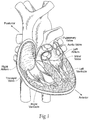
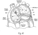
- the heart (see Fig. 1 ) is slightly larger than a clenched fist. It is a double (left and right side), self-adjusting muscular pump, the parts of which work in unison to propel blood to all parts of the body.
- the right side of the heart receives poorly oxygenated ("venous”) blood from the body from the superior vena cava and inferior vena cava and pumps it through the pulmonary artery to the lungs for oxygenation.
- the left side receives well-oxygenation (“arterial”) blood from the lungs through the pulmonary veins and pumps it into the aorta for distribution to the body.
- the heart has four chambers, two on each side -- the right and left atria, and the right and left ventricles.
- the atria are the blood-receiving chambers, which pump blood into the ventricles.
- the ventricles are the blood-discharging chambers.
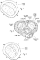
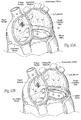
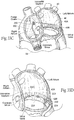
- a wall composed of fibrous and muscular parts, called the interatrial septum separates the right and left atria (see Figs. 2 to 4 ).
- the fibrous interatrial septum is, compared to the more easily shredded muscle tissue of the heart, a more materially strong tissue structure in its own extent in the heart.
- An anatomic landmark on the interatrial septum is an oval, thumbprint sized depression called the oval fossa, or fossa ovalis (shown in Figs.
- the fossa ovalis is the favored site for trans-septal diagnostic and therapeutic procedures from the right into the left heart.
- oxygenated blood from the placenta was directed through the oval foramen into the left atrium, and after birth the oval foramen closes.
- the synchronous pumping actions of the left and right sides of the heart constitute the cardiac cycle.
- the cycle begins with a period of ventricular relaxation, called ventricular diastole.
- the cycle ends with a period of ventricular contraction, called ventricular systole.
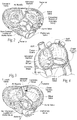
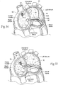
- the heart has four valves (see Figs. 2 and 3 ) that ensure that blood does not flow in the wrong direction during the cardiac cycle; that is, to ensure that the blood does not back flow from the ventricles into the corresponding atria, or back flow from the arteries into the corresponding ventricles.
- the valve between the left atrium and the left ventricle is the mitral valve.
- the valve between the right atrium and the right ventricle is the tricuspid valve.
- the pulmonary valve is at the opening of the pulmonary artery.
- the aortic valve is at the opening of the aorta.
- ventricular diastole i.e., ventricular filling
- the aortic and pulmonary valves are closed to prevent back flow from the arteries into the ventricles.
- the tricuspid and mitral valves open (as Fig. 2 shows), to allow flow from the atria into the corresponding ventricles.
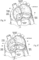
- the tricuspid and mitral valves close (see Fig. 3 ) -- to prevent back flow from the ventricles into the corresponding atria -- and the aortic and pulmonary valves open -- to permit discharge of blood into the arteries from the corresponding ventricles.
- the opening and closing of heart valves occur primarily as a result of pressure differences.
- the opening and closing of the mitral valve occurs as a result of the pressure differences between the left atrium and the left ventricle.
- the mitral valve opens, allowing blood to enter the ventricle.
- the ventricle contracts during ventricular systole, the intraventricular pressure rises above the pressure in the atrium and pushes the mitral valve shut.
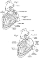
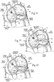
- the mitral and tricuspid valves are defined by fibrous rings of collagen, each called an annulus, which forms a part of the fibrous skeleton of the heart.
- the annulus provides attachments for the two cusps or leaflets of the mitral valve (called the anterior and posterior cusps) and the three cusps or leaflets of the tricuspid valve.
- the leaflets receive chordae tendineae from more than one papillary muscle. In a healthy heart, these muscles and their tendinous cords support the mitral and tricuspid valves, allowing the leaflets to resist the high pressure developed during contractions (pumping) of the left and right ventricles.
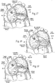
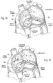
- Figs. 5 and 6 show the chordae tendineae and papillary muscles in the left ventricle that support the mitral valve.
- the anterior portion of the mitral valve annulus is intimate with the non-coronary leaflet of the aortic valve.
- the mitral valve annulus is also near other critical heart structures, such as the circumflex branch of the left coronary artery (which supplies the left atrium, a variable amount of the left ventricle, and in many people the SA node) and the AV node (which, with the SA node, coordinates the cardiac cycle).
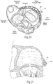
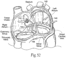
- the coronary sinus and its tributaries are also in the vicinity of the posterior mitral valve annulus. These vessels drain the areas of the heart supplied by the left coronary artery. The coronary sinus and its tributaries receive approximately 85% of coronary venous blood. The coronary sinus empties into the posterior of the right atrium, anterior and inferior to the fossa ovalis (see Fig. 4 ). A tributary of the coronary sinus is called the great cardiac vein, which courses parallel to the majority of the posterior mitral valve annulus, and is superior to the posterior mitral valve annulus by an average distance of about 9.64 +/- 3.15 mm.
- the dimensions of the mitral valve annulus create an anatomic shape and tension such that the leaflets coapt, forming a tight junction, at peak contraction pressures.
- the leaflets coapt at the opposing medial and lateral sides of the annulus are called the leaflet commissures.
- Valve malfunction can result from the chordae tendineae (the chords) becoming stretched, and in some cases tearing. When a chord tears, the result is a leaflet that flails. Also, a normally structured valve may not function properly because of an enlargement of or shape change in the valve annulus. This condition is referred to as a dilation of the annulus and generally results from heart muscle failure. In addition, the valve may be defective at birth or because of an acquired disease.
- mitral valve dysfunction can occur when the leaflets do not coapt at peak contraction pressures.
- Fig. 9 shows, the coaptation line of the two leaflets is not tight at ventricular systole. As a result, an undesired back flow of blood from the left ventricle into the left atrium can occur.
- Mitral regurgitation is a condition where, during contraction of the left ventricle, the mitral valve allows blood to flow backwards from the left ventricle into the left atrium. This has two important consequences.
- blood flowing back into the atrium may cause high atrial pressure and reduce the flow of blood into the left atrium from the lungs.
- fluid leaks into the lungs and causes pulmonary edema.
- the blood volume going to the atrium reduces volume of blood going forward into the aorta causing low cardiac output. Volume overloads the ventricle, as the excess blood in the atrium over-fills the ventricle during each cardiac cycle.
- Mitral regurgitation is measured on a numeric Grade scale of 1+ to 4+ by either contrast ventriculography or by echocardiographic Doppler assessment.
- Grade 1+ is trivial regurgitation and has little clinical significance.
- Grade 2+ shows a jet of reversed flow going halfway back into the left atrium.
- Grade 3 regurgitation shows filling of the left atrium with reversed flow up to the pulmonary veins and a contrast injection that clears in three heart beats or less.
- Grade 4 regurgitation has flow reversal into the pulmonary veins and a contrast injection that does not clear from the atrium in three or fewer heart beats.
- Mitral regurgitation is categorized into two main types, (i) organic or structural and (ii) functional.
- Organic mitral regurgitation results from a structurally abnormal valve component that causes a valve leaflet to flail upward and leak during systole.
- Functional mitral regurgitation results from annulus dilation due to primary congestive heart failure, the latter of which is itself generally surgically untreatable, and not due to a reversible cause like severe ischemia or primary valvular heart disease.
- the fibrous mitral annulus is attached to the anterior mitral leaflet in one-third of its circumference.
- the muscular mitral annulus constitutes the remainder of the mitral annulus and is attached to by the posterior mitral leaflet.
- the anterior fibrous mitral annulus is intimate with the central fibrous body, the two ends of which are called the fibrous trigones. Just posterior to each fibrous trigone is the commissure of which there are two, the anterior and the posterior commissure. The commissure is where the anterior leaflet meets the posterior leaflet at the annulus.
- the central fibrous body is also intimate with the non-coronary leaflet of the aortic valve.
- the central fibrous body is fairly resistant to elongation during the process of mitral annulus dilation. It has been shown that the great majority of mitral annulus dilation occurs in the posterior two-thirds of the annulus known as the muscular annulus. One could deduce thereby that, as the annulus dilates, the percentage that is attached to the anterior mitral leaflet diminishes.
- mitral regurgitation In functional mitral regurgitation, the dilated annulus causes the leaflets to separate anterior from posterior leaflet at their coaptation points in all phases of the cardiac cycle. Onset of mitral regurgitation may be acute, or gradual and chronic in either organic or in functional mitral regurgitation.
- the mitral annulus can dilate to the point of causing functional mitral regurgitation. It does so in approximately twenty-five percent of patients with congestive heart failure. If subjected to exercise, echocardiography shows the incidence of functional mitral regurgitation in these patients rises to over fifty percent.
- Functional mitral regurgitation is a significantly aggravating problem for the dilated heart, as is reflected in the increased mortality of these patients compared to otherwise comparable patients without functional mitral regurgitation.
- One mechanism by which functional mitral regurgitation aggravates the situation in these patients is through increased volume overload imposed upon the ventricle. Due directly to the leak, there is increased work the heart is required to perform in each cardiac cycle to eject blood antegrade through the aortic valve and retrograde through the mitral valve. The latter is referred to as the regurgitant fraction of left ventricular ejection. This is added to the forward ejection fraction to yield the total ejection fraction.
- a normal heart has a forward ejection fraction of seventy percent. With functional mitral regurgitation and dilated cardiomyopathy the ejection fraction is typically less than thirty percent. If the regurgitant fraction is half the ejection fraction in the latter group the forward ejection fraction can be as low as fifteen percent.
- diuretics and/or vasodilators can be used to help reduce the amount of blood flowing back into the left atrium.
- An intra-aortic balloon counterpulsation device is used if the condition is not stabilized with medications.
- surgery to repair or replace the mitral valve is often necessary.
- Surgical edge-to-edge juncture repairs which can be performed endovascularly, are also made, in which a mid valve leaflet to mid valve leaflet suture or clip is applied to keep these points of the leaflet held together throughout the cardiac cycle.
- Edwards Life Sciences Corporation and Evalve Inc. have developed, respectively, a transvascular suture and a clip to grasp and bond the two mitral leaflets in the beating heart.
- Grade 3+ or 4+ organic mitral regurgitation may be repaired with such edge-to-edge technologies. This is because, in organic mitral regurgitation, the problem is not the annulus but in the central valve components.
- the coronary sinus is mechanically deformed through endovascular means applied and contained to function solely within the coronary sinus.
- endovascular coronary sinus technologies to reshape the mitral annulus.
- US 2013/0199974 describes an annuloplasty system for repairing a valve in a patient's heart.
- the system comprises a surgical implant including the member having first and second end portions.
- the implant member is configured and/or adapted to form a partial ring along a portion of one of the valve annulae of a patient's heart such as the mitral or tricuspid valve annulus.
- the implant member is axially elastic such that it can axially expand and contract and includes first and second anchors extending from the end portions of the implant member.
- the anchors are adapted to anchor the implant in tissue such as the mitral or tricuspid valve annulus.
- US 2003/0078465 describes devices and methods for treating degenerative, congestive heart disease and related valvular dysfunctions.
- Percutaneous and minimally invasive surgical tensioning structures are described. These tensioning structures can be implanted within various major coronary blood-carrying conduit structures into or through myocardium or into engagement with other anatomic structures that impact cardiac output to provide tensile support to the heart muscle wall.
- US 5961440 describes an apparatus for treatment of a failing heart by reducing the wall tension therein.
- the apparatus includes a tension member for drawing at least two walls of a heart chamber toward each other.
- One aspect of the disclosure provides devices, systems, and methods for treating a mitral heart valve using an anchor structure that is located within the great cardiac vein.
- the devices, systems, and methods install the anchor structure within the great cardiac vein adjacent a length comprising at least a portion of a posterior annulus of the mitral valve.
- the devices, systems, and methods couple a posterior region of an implant to the anchor structure within great cardiac vein and extend the implant across the left atrium, through an interatrial septum, and into a right atrium.
- the devices, systems, and methods tension the implant and anchor an anterior region of the implant to tissue in or near the right atrium to maintain the tension.
- the tension applied by the implant can improve septal-to-lateral dimensions of the valve and thereby lead to improved leaflet coaption to ameliorate functional mitral valve regurgitation.
- the tension applied by the implant can serve the stabilize the posterior annulus in the manner of an annuloplasty ring, to resist change in annulus size during the cardiac cycle.
- the anchor structure can also serve to consolidate the great cardiac vein into a unified physical structure along its length.
- the tension applied to the implant is uniformly distributed as a force vector to atrial tissue adjacent the posterior mitral valve annulus through the consolidated great cardiac vein.
- the consolidation of tissue can enhance the beneficial effects of the implant.
- the devices, systems, and methods conjoin the great cardiac vein to the left ventricle in a tissue region between the consolidated great cardiac vein and the left ventricle.
- the implant is configured, when placed into tension, to apply a force vector upon the tissue consolidating anchor structure within the great cardiac vein.
- the force vector x can be upward, inward, or a combination of both.
- the force vector is directed by the conjoined tissue region to the left ventricle, to relieve tension on the annulus.
- Another aspect of the disclosure provides devices, systems, and methods for treating a mitral heart valve using an elongated structure sized and configured to be deployed in tension a circumferential path within the great cardiac vein adjacent a posterior annulus of the mitral valve.
- the structure includes an end anchoring region sized and configured to extent from the coronary sinus into the right atrium.
- An anchor couples to the end anchoring region on the interatrial septum in the right atrium.
- the tension applied by the implant can improve septal-to-lateral dimensions of the valve and thereby lead to improved leaflet coaption to ameliorate functional mitral valve regurgitation.
- the tension applied by the implant can serve the stabilize the posterior annulus in the manner of an annuloplasty ring, to resist change in annulus size during the cardiac cycle.
- the elongated structure includes first and second end anchoring regions.
- the elongated structure also includes an intermediate region coupled to the first and second end anchoring regions.
- Each end anchoring region is sized and configured, in use, to extend into the right atrium, while the intermediate region is sized and configured to extend outside the right atrium in a circumferential path within the great cardiac vein adjacent a posterior annulus of the mitral valve.
- An anchor couples to the first and second end anchoring regions in the right atrium or a vena cava to hold the intermediate region in tension within the great cardiac vein.
- the tension applied by the implant can improve septal-to-lateral dimensions of the valve and thereby lead to improved leaflet coaption to ameliorate functional mitral valve regurgitation.
- the tension applied by the implant can serve the stabilize the posterior annulus in the manner of an annuloplasty ring, to resist change in annulus size during the cardiac cycle.
- a first implant is deployed within a heart vessel adjacent to a heart chamber, and a second implant is deployed within the heart chamber.
- a region of the second implant within the heart chamber is magnetically attracting to a region of the first implant within the heart vessel e.g., so that the region of the second implant can be coupled to the region of the first implant within the heart vessel.
- Figs. 10A and 10B show embodiments of an implant 10 that is sized and configured to extend across the left atrium in generally an anterior-to-posterior direction, spanning the mitral valve annulus.
- the implant 10 comprises a spanning region or bridging element 12 having a posterior tissue anchoring region 14 and an anterior tissue anchoring region 16.
- the posterior anchoring region 14 is sized and configured to be anchored in a region of atrial tissue above the posterior mitral valve annulus. This region is preferred, because it generally presents more tissue mass for obtaining purchase of the posterior anchoring region 14 than in a tissue region at or adjacent to the posterior annulus. Engagement of tissue at this supra-annular location also avoids encroachment of and risk of injury to the circumflex coronary artery.
- the anterior anchoring region 16 is sized and configured to be anchored, upon passing into the right atrium through the septum, to tissue in or near the right atrium.
- the anterior anchoring region 16 may be anchored to a region of fibrous tissue in the interatrial septum.
- the anchoring site is desirably superior to the anterior annulus at about the same elevation or higher than the elevation of the posterior tissue anchoring region 14.
- the anterior anchoring region 16 is anchored at or near the inferior rim of the fossa ovalis.
- the anterior anchoring region 16 can be anchored at a more superior position in the septum, e.g., at or near the superior rim of the fossa ovalis.
- the anterior anchoring region 16 can also be anchored in a more superior or inferior position in the septum, away from the fossa ovalis, provided that the anchoring site does not harm the tissue region.
- the anterior anchoring region 16 upon passing through the septum into the right atrium, may be anchored within or otherwise tethered to the superior vena cava (SVC) or the inferior vena cava (IVC), instead of to the septum itself.
- SVC superior vena cava
- IVC inferior vena cava
- the spanning region or bridging element 12 can be placed into tension between the two tissue anchoring regions 14 and 16.
- the implant 10 thereby serves to apply a direct mechanical force generally in posterior to anterior direction across the left atrium.
- the direct mechanical force can serve to shorten the minor axis of the annulus.
- the implant 10 can also reactively reshape the annulus along its major axis and/or reactively reshape other surrounding anatomic structures. It should be appreciated, however, the presence of the implant 10 can serve to stabilize tissue adjacent the heart valve annulus, without affecting the length of the minor or major axes.
- the implant 10 may only need to reshape the annulus during a portion of the heart cycle, such as during late diastole and early systole when the heart is most full of blood at the onset of ventricular systolic contraction, when most of the mitral valve leakage occurs.
- the implant 10 may be sized to produce small or negligible displacement of the annulus to restore or enhance inward movement of the annulus during late ventricular diastolic relaxation, as the annulus dilates and becomes restricted by the implant 10.
- the mechanical force applied by the implant 10 across the left atrium can restore to the heart valve annulus and leaflets a more normal anatomic shape and tension.
- the more normal anatomic shape and tension are conducive to coaptation of the leaflets during late ventricular diastole and early ventricular systole, which, in turn, reduces mitral regurgitation.
- the implant 10 is made from a biocompatible metallic or polymer material, or a metallic or polymer material that is suitably coated, impregnated, or otherwise treated with a material to impart biocompatibility, or a combination of such materials.
- the material is also desirably radio-opaque or incorporates radio-opaque features to facilitate fluoroscopic visualization.
- the implant 10 can be formed by bending, shaping, joining, machining, molding, or extrusion of a metallic or polymer wire form structure, which can have flexible or rigid, or inelastic or elastic mechanical properties, or combinations thereof.
- the implant 10 can be formed from metallic or polymer thread-like or suture material.
- Materials from which the implant 10 can be formed include stainless steel, nitinol, titanium, silicone, plated metals, eljiloy, and NP55.
- the implant 10 can take various shapes and have various cross-sectional geometries.
- the implant 10 can have, e.g., a generally curvilinear (i.e., round or oval) cross-section, or a generally rectilinear cross section (i.e., square or rectangular), or combinations thereof.
- the posterior tissue anchoring region 14 is sized and configured to engage tissue within the left atrium at a supra-annular position, i.e., engaging tissue in the left atrium wall above the posterior annulus.
- the posterior anchoring region 14 is shown to engage tissue generally at the level of the great cardiac vein, which travels adjacent to and in parallel to the majority of the posterior mitral valve annulus.
- This tributary of the coronary sinus can provide a strong and reliable fluoroscopic landmark when a radiopaque device is placed within it or contrast dye is injected into it.
- engagement of tissue at this supra-annular location also lessens the risk of encroachment of and risk of injury to the circumflex coronary artery compared to procedures applied to the mitral annulus directly.
- the great cardiac vein also provides a site where relatively thin, non-fibrous atrial tissue can be readily augmented and consolidated.
- the posterior tissue anchoring region 14 can be coupled to a posterior anchor 18 placed within the great cardiac vein. This makes possible the mechanical fixation of the posterior anchoring region 14 in a non-fibrous portion of the heart in a manner that can nevertheless sustain appreciable hold or purchase on that tissue for a substantial period of time, without dehiscence, expressed in a clinically relevant timeframe.
- the posterior anchor 18 comprises an integral part of the implant 10, being integrally joined to the posterior anchoring region 14 in a generally perpendicular relationship, forming a T-shape.
- the posterior anchor 18 comprises the cross-arm of the T-shape.
- the posterior anchor 18 is elongated sufficiently to traverse inside at least a portion of the great cardiac vein in medial and lateral directions from the posterior anchoring region 14.
- the posterior anchor 18 can be inserted in a laid-back, collapsed condition upon the posterior anchoring region 14, through the lumen of a tissue piercing needle from the left atrium through a wall of the great cardiac vein.
- the posterior anchor 18 can be configured with an elastic memory such that, once free of the needle lumen, it springs open from the collapsed condition into the T-shape, to reside within the great cardiac vein.
- the posterior anchor 18 can have a diameter of about 0.5 mm.
- the posterior anchor 18 comprises a separate structure to which the posterior anchoring region 14 is coupled during implantation.
- the coronary sinus provides an accessible intravascular site from the right atrium, through which the posterior anchor 18 of this type can be placed.
- the posterior anchor 18 comprises mechanical stent-like structure.
- the stent-like structure is desirably relatively large (e.g., at least 10 mm to 20 mm in diameter) to present a large physical and radiopaque target for the posterior anchoring region 14, or any other intra-atrial device attempting to enter or attach to an anchoring structure present within the great cardiac vein.
- the desired large physical size of the posterior anchor 18 further diminishes the likelihood of trauma to the circumflex coronary artery, in comparison to a situation where a smaller structure were placed in the great cardiac vein. A smaller physical target could be more readily missed, and trauma to surrounding tissues could result.
- a smaller structure e.g., approaching 5 mm in diameter
- a larger structure e.g., approaching 30 mm in diameter
- non-fibrous tissue at, above, or below the level of the great cardiac vein e.g., in a range of about 5 to about 25 mm above the plane of the posterior mitral valve annulus
- tissue bulking agents or fibrosis caused, e.g., chemically or by heat can be used to strengthen and consolidate regions of atrial tissue above the annulus for purchase or hold by the posterior tissue anchoring region 14.
- the anterior anchoring region 16 is sized and configured to engage firmly the fibrous tissue and the surrounding tissues in the right atrium side of the atrial septum.
- This fibrous tissue region provides a tissue fixation site of better integrity than muscle in terms of devices pulling through.
- the septum is the most fibrous tissue structure in its own extent in the heart. Surgically handled, it is usually one of the only heart tissues into which sutures actually can be placed and can be expected to hold without pledgetts or deep grasps into muscle tissue, where the latter are required.
- the anterior tissue anchoring region 16 passes through the septal wall at a supra-annular location above the plane of the anterior mitral valve annulus.
- the supra-annular distance on the anterior side can be generally at or above the supra-annular distance on the posterior side.
- the anterior tissue anchoring region 16 is shown in Fig. 10 at or near the inferior rim of the fossa ovalis, although other more inferior or more superior sites can be used within or outside the fossa ovalis, taking into account the need to prevent harm to the septal tissue and surrounding structures.
- the implant 10 By engaging tissue at this supra-annular level within the right atrium, which is fully outside the left atrium and spaced well above the anterior annulus, the implant 10 avoids the impracticalities of endovascular attachment at or adjacent to the anterior annulus, where there is just a very thin rim of annulus tissue that is bounded anteriorly by the anterior leaflet, inferiorly by the aortic outflow tract, and medially by the atrioventricular node of the conduction system.
- the anterior annulus is where the non-coronary leaflet of the aortic valve attaches to the mitral annulus through the central fibrous body.
- Anterior fixation of the implant 10 in the supra-annular level within the right atrium avoids encroachment of and risk of injury to both the aortic valve and the AV node.
- the purchase of the anterior tissue anchoring region 16 in fibrous septal tissue is desirably enhanced by one or more anterior anchors 20.
- the anterior anchor or anchors 20 mechanically amplify the hold or purchase of the anterior anchoring region 16 in the fibrous tissue site.
- the anterior anchor or anchors 20 also desirably increase reliance, at least partly, on neighboring anatomic structures of the septum to anchor and fix the position of the implant 10. Anticipating that pinpoint pulling forces will be applied by the anchoring region 16 to the septum, the forces acting on the anchor 20 should be spread over a moderate area, without causing impingement on valve, vessels or conduction tissues.
- the anchor 20 should also have a low profile configuration and highly washable surfaces to diminish thrombus formation for devices deployed inside the heart.
- a septal brace may be used in combination with the anterior anchor or anchors 20 to distribute forces uniformly along the septum (see Fig. 33A ).
- stents in the IVC or the SVC can be used as anchoring sites (see Fig. 33B and 33C ), instead of anchoring directly to the septum.
- Fixation of the posterior and anterior tissue anchoring regions 14 and 16 having radiopaque anchors and well demarcated fluoroscopic landmarks respectively at the supra-annular tissue sites just described not only provides freedom from key vital structure damage -- e.g., to the circumflex artery, AV node, and the left coronary and non-coronary cusps of the aortic valve - but the supra-annular fixation sites are also not reliant on purchase between tissue and direct tension-loaded penetrating/biting/holding tissue attachment mechanisms. Instead, physical structures and force distribution mechanisms like stents can be used, which better accommodate the attachment of mechanical levers and through which potential tissue tearing forces can be better distributed. Further, the fixation sites do not require the operator to use complex imaging.
- fixation sites also make possible full intra-atrial retrieval of the implant 10 by endovascularly snaring and then cutting the bridging element at either side of the left atrial wall, from which it emerges.
- the implant 10 is shown to span the left atrium beginning at a posterior point of anchorage superior to the approximate mid-point of the mitral valve annulus, and proceeding in an anterior direction in a generally straight path directly to the region of anterior anchorage in the septum.
- the spanning region or bridging element 12 of the implant 10 is preformed or otherwise configured to extend in this essentially straight path above the plane of the valve, without significant deviation in elevation toward or away from the plane of the annulus, other than as dictated by any difference in elevation between the posterior and anterior regions of anchorage.
- Lateral or medial deviations and/or superior or inferior deviations in this path can be imparted, if desired, to affect the nature and direction of the force vector or vectors that the implant 10 applies.
- the spanning region or bridging element 12 can be preformed or otherwise configured with various medial/lateral and/or inferior/superior deviations to achieve targeted annulus and/or atrial structure remodeling, which takes into account the particular therapeutic needs and morphology of the patient.
- the implant 10 is shown to span the left atrium beginning at a posterior region of anchorage that is closer to a lateral trigone of the annulus (i.e., farther from the septum).
- the posterior region of anchorage can be at a position that is closer to a medial trigone of the annulus (i.e., closer to the septum). From either one of these posterior regions of anchorage, the implant 10 can extend in an anterior direction in a straight path directly to the region of anterior anchorage in the septum.
- Fig. 11 like Fig.
- the spanning region or bridging element 12 of the implant 10 is preformed or otherwise configured to extend in an essentially straight path above the plane of the valve, without significant deviation in elevation toward or away from the plane of the annulus, other than as dictated by the difference in elevation, if any, between the posterior and anterior regions of anchorage.
- the spanning region or bridging element 12 of the implant 10 can be preformed or otherwise configured to arch upward above the plane of the valve toward the dome of the left atrium Alternatively (see Fig. 13 ), the spanning region or bridging element 12 of the implant 10 can be preformed or otherwise configured to dip downward toward the plane of the valve toward the annulus, extending close to the plane of the valve, but otherwise avoiding interference with the valve leaflets. Or, still alternatively (see Fig. 14 ), the spanning region or bridging element 12 of the implant 10 can be preformed or otherwise configured to follow a curvilinear path, bending around a trigone (medial or lateral) of the annulus before passage to the anterior anchorage region.
- the spanning region or bridging element 12 can follow a curvilinear path bending around a trigone (medial or lateral) of the annulus as well as elevate in an arch away from the plane of the valve.
- the spanning region or bridging element 12 can follow a curvilinear path bending around a trigone (medial or lateral) of the annulus as well as dip toward the plane of the valve.
- FIG. 17 shows a system 22 comprising a lateral implant 10L and a medial implant 10M of the types previously described.
- Fig. 17 shows the implants 10L and 10M being fixed at a common anterior anchorage region. It should be appreciated that the implants 10L and 10M can include spaced apart anterior anchorage regions.
- One or both of the implants 10L and 10M can be straight (as in Fig. 11 ), or arch upward (as in Fig. 12 ), or bend downward (as in Fig. 13 ).
- a given system 10 can comprise lateral and medial implants 10L and 10M of different configurations.
- a given system 22 can comprise more than two implants 10.
- Fig. 18 shows a system 22 comprising two curvilinear implants 10L and 10M of the type shown in Fig. 14 .
- the curvilinear implants 10L and 10M are shown to be anchored at a common posterior anchorage region, but the implants 10 can proceed from spaced apart posterior anchorage regions, as well.
- One or both of the curvilinear implants 10L and 10M can be parallel with respect to the plane of the valve (as in Fig. 14 ), or arch upward (as in Fig. 15 ), or bend downward (as in Fig. 16 ).
- a given system 22 can comprise curvilinear implants 10L and 10M of different configurations.
- Fig. 19 shows a system 22 comprising a direct middle implant 10D, a medial curvilinear implant 10M, and a direct lateral implant 10L.
- a direct middle implant 10D a direct middle implant 10D
- a medial curvilinear implant 10M a direct lateral implant 10L.
- One, two, or all of the implants 10 can be parallel to the valve, or arch upward, or bend downward, as previously described.
- the posterior tissue anchoring region 14 desirably includes one or more posterior anchors 18 placed in the great cardiac vein to enhance its purchase in supra-annular tissue in the left atrium.
- the posterior anchor 18 can be variously constructed.
- the anchor 18 may be rigid, or flexible, or elastic, or malleable, or solid, or porous.
- the anchor 18 can sized and configured to provide a localized anchoring site, or be elongated and extend medially and laterally from the intended anchoring site to better consolidate atrial tissue at the level of the vein along the length of the vein.
- the anchor 18 can comprise a stent-like structure 24 that is sized and configured to be introduced into the great cardiac vein, e.g., through the coronary sinus os in the right atrium (as will be described in greater detail later).
- the structure 24 can comprise an expandable scaffold, which can take the form of a self-expanding stent, or a malleable structure that is expanded by means of an interior force, e.g., a balloon.
- the structure 24 can be flexible, or semi-rigid, or rigid, or have regions of different mechanical characteristics.
- the anchor 18 can comprise a preformed, non-expandable hollow tube or solid rod of a pre-determined shape, which is sized and configured to be advanced into the great cardiac vein. Still alternatively, the anchor 18 can comprise an inert biocompatible bulking material injected into the vein, which cures to possess a desired mechanical property. Or, the anchor 18 can include a hollow structure that is at least a partially-filled with an inert biocompatible material, which cures to possess a desired mechanical property.
- the anchor 18 is desirably radio-opaque or incorporates radio-opaque features to facilitate fluoroscopic visualization when positioned in a tributary of the coronary sinus.
- the anchor 18 may be held in position within the vein by gripping the surrounding vessel wall, e.g., by barbs, tines, or the like. If desired, the anchor 18 may be further secured by suture, adhesive; or like material within the vein.
- the anchor 18 can incorporate roughened or porous surfaces and/or be coated with or allow injection of other materials (e.g., polyester fabric, irritative agents, or drug agents) to promote tissue in-growth. To enhance fibrosis and potentially diminish the likelihood of tissue dehiscence in and around the great cardiac vein at the time the anchoring region 14 is used, the anchor 18 may be placed within the great cardiac vein a number of weeks in advance of the anchoring region 14.
- the posterior anchoring region 14 is sized and configured to be manipulated within the left atrium outside the vein, and to lock into or otherwise gain purchase with the anchor 18 that resides within the vein.
- the posterior anchoring region 14 can comprise a hook or T-shaped structure that locks from outside the vein into the material or structure of the anchor 18 residing within the vein.
- the cross-arm of the T can itself serve as the anchor 18 with a separately deployed structure.
- the posterior anchoring region 14 can comprise suture material that is threaded from outside the vein through the material or structure of the anchor 18 residing within the vein.
- the anterior anchoring region 16 is sized and configured to pass through the septum and project into the right atrium. There, the anterior anchor 20 captures the anterior anchoring region 16 and holds the anchoring region 16 against the fibrous and surrounding muscular tissue of the septum in the right atrium.
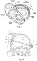
- the anterior anchor 20 can be variously constructed. In the illustrated embodiment (see, e.g., Figs. 10 , 22, and 23 ), the anterior anchor 20 takes the form, fit, and function of an anchor button that is secured to the anterior anchoring region.
- the anchor button 20 includes barbed stays 25 that brace against the septum. The stays 25 can be crimped to the anterior anchoring region 16 to maintain a desired degree of tension on the spanning region or bridging element 12 within the left atrium.
- An anchor button 22 can be located only on the right atrium side of the septum, or both left and right atrium sides of the septum.
- the anterior anchoring region 16 (or the entire implant 10, for that matter) can comprise suture material that is threaded through the fibrous wall of the septum, with or without the use of an anchor button or the like.
- an anchor button or the like In the latter case a more proximal vena caval anchor would supplant the need for using the inter-atrial septum as an anchor.
- the anchoring site can be within either the SVC or IVC, instead of to the septum.
- the implants 10 or implant systems 22 as just described lend themselves to implantation in a heart valve annulus in various ways.
- the implants 10 or implant systems 22 can be implanted, e.g., in an open heart surgical procedure.
- the implants 10 or implant systems 22 can be implanted using catheter-based technology via a peripheral venous access site, such as in the femoral or jugular vein or femoral artery (via the IVC or SVC) under image guidance, or trans-arterial retrograde approaches to the left atrium through the aorta also under image guidance.
- the implants 10 or implant systems 22 can be implanted using thoracoscopic means through the chest, or by means of other surgical access through the right atrium, also under image guidance.
- Image guidance includes but is not limited to fluoroscopy, ultrasound, magnetic resonance, computed tomography, or combinations thereof.
- Figs. 24 to 30 show a representative embodiment of the deployment of an implant 10 of the type shown in Fig. 10 by a percutaneous, catheter-based procedure, under image guidance.
- Percutaneous vascular access is achieved by conventional methods into the femoral or jugular vein.
- a first catheter 26 is steered through the vasculature into the right atrium. It is the function of the first catheter 26 to deploy the posterior anchor 18 into the great cardiac vein through the coronary sinus.
- Catheter access to the coronary sinus can be achieved through either a femoral vein to IVC or SVC route (in the latter case, for a caval brace) or an upper extremity or neck vein to SVC or IVC route (in the latter case, for a caval brace) .
- the shortest access is from the upper extremity or neck venous system; however, the IVC can also be access by passing through the SVC and right atrium.
- the shortest access to the IVC is through the femoral vein; however the SVC can also be access by passing through the IVC and right atrium.
- Figs. 24 to 30 show access through a SVC route for purposes of illustration. In a later described implantation technique (see Figs. 36 to 39 ), access though an IVC route is shown for purposes of illustration.
- the first catheter 26 advances the anchor 18, e.g., through the coronary sinus os in the right atrium, into the great cardiac vein above and in parallel to the posterior mitral valve annulus.
- a guide wire (not shown) may be used to guide the advancement.
- the anchor 18 is extended to a length sufficient to accommodate the desired site of fixation for the posterior anchoring region 14 of the implant 10.
- the length of the posterior anchor may extend from 20 mm to 200 mm as it lies inside the coronary venous system.
- the desired position of the posterior anchor 18 can be secured, e.g. by self-expansion or the use of a balloon to cause expansion within the vein, or it may require no conformational change from its shape inside the delivery catheter.
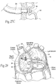
- Fig. 25 shows, upon securing the position of the posterior anchor 18 within the vein, the first catheter 26 is withdrawn (the guide wire, if used, may be left inside the posterior anchor 18 within the coronary vein), and a second catheter 28 is steered through the vasculature into the right atrium.
- the second catheter 28 carries the anterior anchor 20, which it fixes to the septum.
- the second catheter 28 also carries a distal needle (not shown), which is deployed to pierce the septum between the right and left atrium.
- the needle pierces the fossa ovalis near its inferior rim.
- the fossa ovalis is selected because it constitutes a safe structure to traverse and has an anatomic landmark that can be readily accessed by conventional intravascular techniques and pierced for the purpose of gaining access to the left atrium from the right atrium through the septum.
- Catheter access to the fossa ovalis can be achieved through either a femoral-IVC or internal jugular-SVC route (a femoral-SVC route is shown simply for purposes of illustration).
- Fig. 25 shows, once access between the right and left atriums is opened, a guide wire 32 is advanced trans-septally through the needle catheter 28 into the left atrium.
- the second catheter 28 is withdrawn ( Fig. 26A shows its absence).
- an implant delivery catheter 34 is advanced over the guide wire 32 trans-septally through the fossa ovalis puncture (through the already delivered anchor 20, which is attached there) and into the left atrium.
- the implant delivery catheter 34 can be deployed trans-septally by means of surgical access through the right atrium.
- the implant delivery catheter 34 is directed to a targeted posterior anchoring site at the level where the posterior anchor 18 resides within the great cardiac vein.
- the implant delivery catheter 34 can include an on-board distal steering mechanism, to direct the catheter 34 to the intended site with image guidance.
- the anchor 18 residing within the great cardiac vein can carry one or more magnetic elements 210 along its length (either as part of the anchor 18 or within a separately delivered catheter that temporarily supplies the magnetic force required), which coincide with the targeted anchoring site(s).
- the distal end of the implant delivery catheter 34 can include a magnetic element 212 or soft ferromagnetic material that is magnetically attracted to the magnetic element within the great cardiac vein at the intended anchoring site.
- the implant delivery catheter 34 is manipulated by imagining, magnetic guidance catheter or other means described herein or in standard interventional or surgical practice, to puncture atrial tissue at the anchoring site into the great coronary vein.
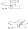
- the posterior anchoring region 14 of the implant 10 is advanced from the implant delivery catheter 34 into the great cardiac vein (as Fig. 27B shows) to attach to the posterior anchor 18 that resides there, as illustrated in this case with a hooking attachment locking mechanism (as Fig. 27C shows).
- the anchoring region 14 can include a grasper that grasps through tissue and into a strut of the posterior anchor 18 inside the great cardiac vein to gain attachment.
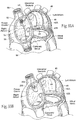
- Fig. 28 shows, once attachment between the posterior anchoring region 14 and the posterior anchor 18 is made, the implant delivery catheter 34 is drawn out of the great cardiac vein and anteriorly across the left atrium. The spanning region or bridging element 12 of the implant 10 is thereby deployed from the catheter 34 within the left atrium. In this way, the anterior anchoring region 16 is lead back through the septum and into the right atrium.
- the implant delivery catheter 34 can exert a pulling force on the spanning element or bridging element 12 as it slides through the already attached anterior anchoring region 16 from within the right atrium, to place the spanning region or bridging element 12 in a desired amount of tension.
- anterior anchoring region 16 can be released from the implant delivery catheter 34 and a suitable grasping instrument (for example, a 7 French grasper) can be deployed in the right atrium to take hold of the anchoring region 16 in the right atrium to place the spanning region 12 in a desired amount of tension, while the anterior anchoring region 16 is slid forward by the guiding catheter to achieve the proper tensioning.
- a suitable grasping instrument for example, a 7 French grasper
- the anterior anchor 16 can include a cinch release mechanism, which can be snipped with a cutting tool and another anchor threaded over the proximal wire component of the bridging or spanning element 12. The latter is snipped when adjustments have been finalized.
- pulling inwardly toward the left atrium on the anterior anchoring region 16 exerts a pulling force on posterior atrial tissue in the region where the posterior anchoring region 14 is attached to the posterior anchor 18.
- the pulling force draws the posterior atrial tissue inwardly toward the anterior atrial tissue of the left atrium.
- the existence of the elongated posterior anchor 18 serves to consolidate the length of the great cardiac vein, thereby distributing the pulling force laterally and medially.
- the pulling force can serve to shorten the annulus along its minor axis.
- the presence of the anchor 18 within the great cardiac vein consolidates the length of the great cardiac vein into a unitary physical structure, which, when pulled upon at least at one point, serves to compress the whole posterior annulus.
- the physician can elect to monitor the incidence of mitral regurgitation by various conventional means, e.g., by contrast ventriculography or by echocardiographic Doppler assessment, as tension is progressively applied to the implant 12. If the physician chooses this approach, the physician can dynamically adjust tension on the implant 12 to achieve a desired diminution or elimination of the incidence or mitral regurgitation.
- Fig. 29 shows, once the implant 12 is satisfactorily positioned and/or the desired therapeutic result is achieved, the physician introduces a tool 36 that crimps a clip 38 or a functionally equivalent mechanism to the anterior anchoring region 16, to hold fast the anterior anchoring region 16 to the anchor button 20.
- the anterior anchoring region 16 can be threaded, and a nut delivered and threaded to the region 16 to retain the anterior anchoring element 16 in the desired degree of tension.
- Fig. 30 shows, the anterior anchoring region 16 is cut next to clip 38 (or nut), ending the installation, and the intravascular tool or tools are withdrawn.
- the projection of the anterior anchoring region 16 into the right atrium facilitates repositioning, retensioning, and/or retrieval of the implant 12 from the right atrium, if necessary or desired.
- trans-septal embodiments just described with straight or linear bridging elements apply a main force vector that is directed essentially across the left atrium (i.e., at about a fifteen to less than forty-five degree vector above the horizontal) from a posterior region above the mitral valve annulus to an anterior septal tissue region, which is also above the mitral valve annulus.
- Use of the implant 10 or implant system 22 for this purpose can provide significant amelioration of mitral regurgitation.
- Fig. 31 shows an implant system 40 for treating mitral regurgitation that applies, either alone or in conjunction with horizontal force vectors, a superior or upward lifting force vector(i.e., at a vector greater than about forty-five degrees above the horizontal) upon tissue in the region of the mitral valve annulus.
- the upward lifting force releases or dissipates tension on the mitral valve annulus from the posterior mitral annulus of the left heart into the implant and brace system of the right heart. It also imposes a more direct vertical force vector component upon atrial tissue between the great cardiac vein and the left ventricle so that the application of horizontal force vectors more directly leads to a desired compressive effect upon the annulus.
- Tension on the mitral valve annulus can arise when the left ventricle and annulus become dilated.
- the magnitude of the tension on the annulus can be significant in situations involving functional mitral regurgitation, particularly functional mitral regurgitation of at least Grade 2+.
- the mitral chordae become tense, pulling the coaptation points down and away from each other.
- the annulus-to-leaflet junction becomes taut.
- An analogy is midline poles (the annulus) holding up a bi-leaf tent (the leaflets), with ropes and stakes (the chordae) holding the tent leaves tautly (the taut leaflets) to the ground (the papillary muscles).
- the implant system 40 imposes a lifting force vector on the annulus (a ventricular structure) by pulling upward on an atrial structure.
- the system 40 includes a tissue consolidating component 42A, which consolidates the great cardiac vein into a unified physical structure along its length.
- the system 490 also includes bonding means 42B for conjoining or bonding the great cardiac vein to the ventricle in the region between the great cardiac vein and the ventricle. In this way, as the system 40 pulls upward on a consolidated great cardiac vein (an atrial structure), a lifting force vector is transferred by the conjoined great vein-ventricle tissue region upon the ventricle.
- the implant system 40 shown in Fig. 31 comprises a tissue-consolidating component 42A.
- the 'tissue-consolidating component 42A consolidates the great cardiac vein into a unified physical structure along its length, so that a lifting force applied at one or more points along the length of the great cardiac vein serves to lift the entire great cardiac vein along its length.
- the tissue-consolidating component 42A resides, in most part, in the great cardiac vein. It can be sized and configured the same way as the posterior anchor 18 previously described.
- the tissue-consolidating component 42 can also be introduced and stabilized in the great cardiac vein in the same fashion as already described.
- the tissue-consolidating component 42A is desirably ring-like, extending from the great cardiac vein to the coronary sinus os adjacent the majority of the length of the posterior mitral annulus within the great cardiac vein. As such, the tissue-consolidating component 42A is located some 5mm to 20mm above the ventricular muscle.
- the tissue consolidating component 42A desirably incorporates radio-opaque features to facilitate fluoroscopic visualization.
- the bonding means 42B conjoins or bonds the great cardiac vein to the ventricle in the region between the great cardiac vein and the ventricle.
- the means 42B bonds non-fibrous, thin atrial tissue at and below the great cardiac vein to the mitral valve annulus.
- the means 42B in effect bonds the component 42A that consolidates the great cardiac vein to the left ventricular muscle base proximate to the posterior mitral annulus, so that lifting and horizontal forces applied to the component 42 are directly transferred to lifting and/or compression of the annulus itself.
- the means 42B also diminishes the possibility of a Type 1 left ventricular rupture between the great cardiac vein and the top of the left ventricle as a result of the forces applied to the component 42 over time.
- the means 42B for bonding of the great cardiac vein to the ventricle can take various forms.
- Mechanical means such as staples can be attached between the component 42A and tissue in the left ventricle.
- Drugs, and/or irritative agents, and/or heat (e.g., radiofrequency heating), and/or chemical agents can be applied to tissue in the region.
- tissue at or near the great cardiac vein can be subject to fibrosis to reinforce the tissue and elevate the pull-through threshold of the component 42A. Fibrosis can be accomplished by the use of polyester coatings, drugs, irritative agent elutions, or combinations thereof. Fibrosis can also be achieved by the application of heat.
- the means 42B can comprise an array of magnets 220 carried by the tissue-consolidating component 42A and an array of magnets or soft ferromagnetic elements 222 that are surgically placed beneath the posterior annulus.
- the polarity of the magnets 220 is selected to magnetically attract the magnetic or soft ferromagnetic elements 222.
- the elements 222 were magnets, soft ferromagnetic materials could be used within the great cardiac vein in lieu of the magnets 220.
- the elements 222 are carried for implantation by expandable or inflatable bodies 224, e.g., balloons.
- the bodies 224 can be individually placed by deployment of a catheter through the aortic valve into the left ventricle, into spaced apart locations under the posterior leaflet.
- the bodies 244 can be expanded or inflated to stabilize the position of the elements 222, e.g., by injection of saline. The magnetically attraction between the magnets 220 and elements 222 draws the two tissue region together, thereby bonding the great cardiac vein to the posterior annulus.
- the system 40 also comprises one or more lifting components 44.
- the lifting component 44 has a posterior anchoring region 46 within the left atrium that couple's to the tissue-consolidating component 42A residing within the great cardiac vein.
- at least one lifting component 44 has a posterior anchoring region 46 coupled to the tissue-consolidating element 42A superior to and in alignment with the approximate mid-point of the mitral valve annulus, as Fig. 31 shows.
- other lifting elements 44 can be deployed on medial and/or lateral sides of the posterior annulus, at or near one or both trigones.
- At least one of the lifting components 44 has a spanning region or bridging element 48 that is preformed or otherwise configured to extend high within the left atrium, upward from its anchoring point with the tissue-consolidating component 42A, and toward the dome of the left atrium.
- the lifting component 44 also includes an anterior anchoring region 50 that passes out of the left atrium and into the right atrium through fibrous tissue of the high septum.
- the anterior anchoring region 50 is shown anchored at or near the superior rim of the fossa ovalis.
- the anterior region of the lifting component 44 can be anchored to or otherwise tethered within the SVC or IVC, and not anchored to the septum itself. In this arrangement (see Fig.
- the lifting component 44 with the high atrial bridging element 48 can pass through the septum high in the fossa ovalis, without anchoring to septal tissue, and be anchored or tethered instead to a stent in the SVC. This arrangement is believed to maximize the effect of the lifting vector.
- the lifting component 44 (desirably without a high atrial bridging element 48) can pass through the septum low in the fossa ovalis, without anchoring to septal tissue, and be anchored or tethered instead to a stent in the IVC.
- the lifting component 44 can be formed by bending, shaping, joining, machining, molding, or extrusion of a metallic or polymer wire form structure, which can have flexible or rigid, or inelastic or elastic mechanical properties.
- the lifting component 44 can take various shapes and have various cross-sectional geometries.
- the lifting component can have, e.g., a generally curvilinear (i.e., round or oval) cross-section, or a generally rectilinear cross section (i.e., square or rectangular), or combinations thereof.
- the lifting component 44 is "elastic.”
- the lifting component 44 is sized and configured to possess a normal, unloaded, shape or condition, in which the component is not in compression or tension.
- the material of the lifting component 44 is selected to possess a desired spring constant.
- the spring constant imparts to the component 44 the ability to be elastically stretched and placed in tension in response to external pulling applied at the anterior anchoring region 50 when the posterior anchoring region 46 is coupled to the tissue consolidating component 42A.
- the lifting component 44 applies an upward force (e.g., with a force vector of great than about 45° above horizontal) upon the tissue-consolidating component 42A.
- the system 40 further comprises an anchor 52 sized and configured to be coupled to the anterior anchoring region 50 of the lifting component 44 in the right heart.
- the anchor 52 holds the lifting component 44 in tension against the septum in the right atrium.
- stents or equivalent non-obstructing anchors in the IVC or SVC can serve as anchoring sites for the lifting component or components 44.
- the lifting component and anchoring component desirably incorporates radio-opaque features to facilitate fluoroscopic visualization.
- the system 40 may include more than one lifting component 44.
- Multiple lifting components 44 may be coupled at spaced locations along the consolidating component 42A, for example, three lifting components 44 coupled at or near the mid posterior annulus and the lateral and medial trigones.
- the anterior anchoring regions 50 of the lifting components 44 may be passed through a single opening at or near the superior rim of the fossa ovalis in the high interatrial septum into the right atrium, and there joined and retained by a single anchor 32.
- the arched lifting components 44 which elevate a consolidated great cardiac vein vertically, while bringing it horizontally inward toward the septum, provide mural support to the wall of the left atrial chamber.
- the components of the system 40 when assembled in the manner shown in Figs. 31 to 33 , unload tension from the mitral annulus in late diastole and early systole dynamically through dissipation of some of the wall tension that tends to expand the annulus.
- the great cardiac vein, reinforced and consolidated by the consolidating component 42 becomes the lever upon which the spring-like lifting component 44 or components act to dynamically unload the base of the left ventricle by dissipating ventricular muscle wall tension and relaying it through the now-consolidated AV groove.
- the spring-like lifting component 44 or components become maximally loaded at end-diastole and in early systole, when the mitral valve area is the least and functional mitral regurgitation is most likely to occur.
- the spring energy unloads the ventricular muscular wall tension at end-diastole and early systole, and the annulus is relieved of tension (at least partially) enough to release or dissipate tension from tented mitral leaflets, thereby allowing improved re-approximation of the mitral leaflets especially in late diastole and early systole to allow closure.
- the system 40 may also, as a primary or secondary effect, result in re-shaping the annulus.
- the system 40 can include auxiliary implant components 60 that extend either across the minor axis of the annulus to shorten the minor axis, or across the major axis of the annulus to shorten or lengthen the major axis, or both minor and major axes can be treated simultaneously.
- implant components 60 can be sized and shaped so that, in use, they apply, in conjunction with the unloading force of the system 40, one or more direct mechanical forces along the minor axis, major axis, or both axes of the annulus, to reshape the annulus.
- the lifting forces imposed by the system 40 lessen the horizontal leading length of atrial tissue between the great cardiac vein and the ventricle, which must be moved in order to achieve any compressive effect on the posterior annulus imposed by forces applied to an anchor in the great cardiac vein.
- the posterior-to-anterior force vectors and/or the medial-to-lateral force vectors imposed by the auxiliary component or components 60 can work in tandem to achieve the desired result.
- the remodeling effects of the auxiliary component or components 60 can thereby be magnified in the presence of the annulus lifting forces imposed by the system 40.
- the auxiliary implant components 60 can be made -- e.g., by bending, shaping, joining, machining, molding, or extrusion -- from a biocompatible metallic or polymer material, or a metallic or polymer material that is suitably coated, impregnated, or otherwise treated with a material to impart biocompatibility, or a combination of such materials.
- the material is also desirably radio-opaque or incorporates radio-opaque features to facilitate fluoroscopic visualization.
- the auxiliary implant components desirable include struts that engage supra-annular tissue.
- auxiliary implant components 60 Further details of implants that can be used as auxiliary implant components 60 are shown in co-pending United States Patent Application Serial No. 10/677,104, filed October 1, 2003 , and entitled “Devices, Systems, and Methods for Reshaping a Heart Valve Annulus” ( US 2004-0127982 ).
- the implant systems 40 as just described lend themselves to implantation in a left and right heart in various ways.
- the systems can be implanted, e.g., in an open heart surgical procedure.
- the systems can be implanted using catheter-based technology via a peripheral venous access site, such as in the femoral, jugular, subclavian vein or femoral artery, under image guidance.
- Figs. 24 to 30 show a representative embodiment of a percutaneous, catheter-based procedure that, under image guidance, can implant the system 40.
- the systems 40 can be implanted using thoracoscopic means through the chest, or by means of other surgical access through the right atrium, also under image guidance.
- Image guidance includes but is not limited to fluoroscopy, ultrasound, magnetic resonance, computed tomography, or combinations thereof.
- implant system 40 as described can be sized and configured to allow leaflets to coapt in the face of functional mitral regurgitation above Grade 1+, including up to Grade 4+, which could be ameliorated at least to some significant extent.
- the system provides rapid deployment, facile endovascular delivery, and full intra-atrial retrievability.
- the system also provides strong fluoroscopic landmarks.
- any intra-atrial system with a trans-septal component deployed within the left atrium - e.g., the systems 40 shown in Figs. 31 to 32 or the implants 10 shown in Figs. 10 to 19 -- can also include right heart components 54 that act as braces to stabilize the septal anchor 20 or 52 relative to the tissue-consolidating component 18 or 42.
- any intra-atrial system with a trans-septal component deployed within the left atrium - e.g., the systems 40 shown in Figs. 31 to 32 or the implants 10 shown in Figs. 10 to 19 -- can also include right heart components 54 placed within or tethered to the SVC or IVC, which anchor the intra-atrial components relative to the tissue consolidating component.
- the right heart component 54 includes a septum brace bar 56 that is coupled to the septal anchor 52.
- the brace bar 56 desirably extends superiorly and inferiorly along the septum from the anchor 52, to distribute forces uniformly along the septum.
- a brace bar 56 of the type shown in Fig. 33A can also be coupled in the same fashion to the anchor 20, when used in combination with the implant 10 shown in Fig. 10 .
- the right heart components 54 may also include stents 58 placed either in the inferior vena cava (IVC), superior vena cava (SVC), or coronary sinus (CS), or the right atrium in general, which are coupled to the brace bar 56.
- the right heart stents 58 serve as braces to further disperse and absorb forces from the lifting component into the right heart.
- a given intra-atrial bridging component e.g., implant 10 in Fig. 10 or component 44 in Fig. 31
- the intra-atrial bridging component is not anchored to the septum, but rather can pass through the septum (e.g., at the fossa ovalis) directly to the anchoring stent 58.
- a washer 200 may be provided on the septum that permits the bridging component to pass through the septum without tearing, but does not anchor the component.
- an element 202 e.g., a cable or memory shaped alloy or tether 202, couples the bridging component to the stent 58, which serves to anchor the bridging component.
- the washer 200 is located high on the fossa ovalis, and the element 202 is coupled to a stent 58 in the SVC. It is believed that this arrangement maximizes the magnitude of the upward lifting (vertical) vector generated by the bridging component BC on the tissue-consolidating component 42 in the great cardiac vein.
- the washer 200 is located low on the fossa ovalis, and the element 202 is coupled to a stent 58 in the IVC. It is believed that this arrangement maximizes the magnitude of the horizontal vector generated by the bridging component BC on the tissue-consolidating component 42 in the great cardiac vein.
- the right heart components 54 described above lend themselves to implantation in any of the manners previously described.
- the tissue-consolidating component 42 (which can comprise, e.g., a rigid, malleable, radiopaque-marked stent dilated to 10 mm to 25 mm in diameter) can be placed by a catheter into the great cardiac vein, as before described. If the bracing stent 58 is intended to rest in the IVC, a femoral vein into the IVC route can be used. If the bracing stent 58 is intended to rest in the SVC, then a jugular vein into the SVC route is selected.
- a guide sheath is then placed through a femoral vein-IVC-fossa ovalis route across the left atrium to the tissue-consolidating component 42.
- the element 202 is passed through the guide sheath.
- the element 202 carries at its distal end a grasper (which can be sized, e.g., 7 French) .
- the grasper grasps onto a strut of the tissue consolidating stent 42 and locks that grasp.
- the element 202 is then drawn across the left atrium, through the fossa ovalis. Tension is applied from within the right atrium to pull the tissue-consolidating stent 42 up and in inside the left atrium. The tension is set to moderate or eliminate the functional MR as much as possible.
- the caval stent 58 (e.g., measuring 5cm to 10 cm long, and 3cm to 7cm diameter) is threaded over the element 202 into the vena cava where catheter access for the element 202 was achieved.
- the stent 58 gets placed just above the liver and just below the right atrium.
- a lock device is threaded over the element 202 from its proximal end up to the caval stent 58.
- the element 202 is then cut below the lock nut and the element 202 below the nut is removed.
- the stent 58 serves to hold and lock the element 202 in its vertical position.
- Fig. 35 shows a loop implant system 70 for treating mitral regurgitation that applies, either alone or in conjunction with other force vectors, a circumferential force vector upon tissue in the region of the posterior mitral valve annulus.
- the inward radial force vector compresses the posterior annulus with a sphincter-like effect, as well as toward to septum, reducing dilation.
- the system 70 includes an elongated implant 72 having first and second anchoring regions 74 and 76, and an intermediate region 78 extending between them.
- the implant 72 is sized and configured to be deployed as a loop, which (i) extends from the first anchoring region 74 on the interatrial septum in the right atrium or in a vena cava, (ii) passes within the right atrium through the coronary sinus and, from there, the intermediate region 78 resides within the great cardiac vein parallel and superior to the posterior mitral annulus, (iii) exits the great cardiac vein through a sidewall of a stent or midrange of a T-shaped tubular device, an end of a stent or tubular anchor device located inside the great coronary vein, and then through the adjacent inner wall of atrial tissue at or near the region of the lateral trigone, (iv) from there, extends in a posterior-to-anterior direction across the left atrium, through the interatrial septum
- the anchoring site for the anchor 80 is shown to be superior to the plane of the anterior mitral valve annulus. More particularly, the anchoring site for the anchor 80 is within the fossa ovalis. This is because the fossa ovalis presents a fibrous tissue region that can be accessed and fastened to with relative technical ease, given conventional interventional radiological and surgical skills and techniques. It should be appreciated other more inferior or more superior sites can be used as trans-septal points of passage to optimize bridging element vectors in the septum, taking into account the same technical and surgical considerations.
- the loop implant 70 serves to apply a direct mechanical force that pulls radially inward upon the posterior annulus.
- the direct mechanical force can serve to shorten the minor axis of the annulus.
- the implant 70 can also reactively reshape the annulus along its major axis and/or reactively reshape other surrounding anatomic structures. It should be appreciated, however, the presence of the implant 70 can serve to stabilize tissue adjacent the heart valve annulus, especially at different and important times in the cardiac cycle when valve coaptation should be improved (e.g., late diastole and early systole), without affecting the length of the minor or major axes.
- the mechanical force applied by the implant 70 to the tissues attached to the annulus can restore to the heart valve annulus and leaflets a more normal anatomic shape and tension, conducive to coaptation of the leaflets during ventricular systole.
- the implant 70 can thus reduce the incidence of mitral regurgitation.
- the mechanical force of the loop implant 70 also pulls upward (i.e., with a vertical force vector) on the posterior annulus.
- This vertical vector is further enhanced when anchorage originates in the superior vena cava and a more vertical pull is exerted on the bridging element or bridge from this vantage than can be from a septal anchor.
- This vertical force vector can also serve to unload tension on the annulus, as well as to lessen the horizontal leading length of atrial tissue between the GCV and the ventricle, which must be moved by an anchor in the GCV in order to achieve any compressive effect on the posterior annulus, with the beneficial effects previously described.
- the magnitude of the vertical vector can be enhanced if the right side bridging element is anchored to a stent in the SVC in the manner shown in Fig. 33B , instead of to the septal wall itself.
- the loop implant 70 can also be anchored to a stent in the IVC in the manner shown in Fig. 33C , where in select situations the inverse may apply to the case of the SVC application.
- the implant 70 is made from a biocompatible metallic or polymer material, or a metallic or polymer material that is suitably coated, impregnated, or otherwise treated with a material to impart biocompatibility, or a combination of such materials.
- the material is also desirably radio-opaque or incorporates radio-opaque features to facilitate fluoroscopic visualization.
- the portion of the intermediate region 78 that resides within the great cardiac vein can comprise a stent-like structure that is sized and configured to be introduced into the great cardiac vein through the coronary sinus os in the right atrium.
- the intermediate region 78 can comprise an expandable scaffold, which can take the form of a self-expanding stent, or a malleable structure that is expanded by means of an interior force, e.g., a balloon.
- the intermediate region 78 may be held in position within the vein by gripping the surrounding vessel wall, e.g., by barbs, tines, or the like. If desired, the intermediate region 78 may be further secured by suture, adhesive, or like material within the vein.
- the intermediate region 78 can incorporate roughened or porous surfaces and/or other materials (e.g., polyester fabric) to promote tissue in-growth.
- the anchoring regions 74 and 76 can comprise wire-form structures formed by bending, shaping, joining, machining, molding, or extrusion of a metallic or polymer wire form structure to the intermediate region 78.
- the material of the implant 70 is selected to impart elastic mechanical properties.
- the loop implant 70 lends itself to implantation in a heart valve annulus in a beating heart or an open heart surgical procedure, or by catheter-based technology via a peripheral venous access site under image guidance, or by closed chest thoracoscopic means through the chest, or by means of other open chest surgical access through the right atrium under image guidance.
- percutaneous vascular access can be achieved by conventional methods into the femoral or jugular or subclavian vein to deploy a first catheter 82 into the right atrium.
- the first catheter 82 advances the implant 70, anchoring region 76 first, through the coronary sinus os in the right atrium and into the great cardiac vein.
- the anchoring region 76 and intermediate region 78 are advanced into the great cardiac vein, such that the anchoring region 76 is located at or near the lateral trigone.
- Fig. 36 shows access through the femoral-IVC route for purposes of illustration.
- a second catheter 84 is steered through the vasculature (also via the IVC) into the right atrium.
- the second catheter 84 carries a distal needle (not shown), which is deployed to pierce the septum between the right and left atrium (e.g., at the fossa ovalis).
- a guide wire 32 is advanced trans-septally through the needle catheter 84 into the left atrium.
- the second catheter 84 is withdrawn (see Fig. 38 ), and, under image guidance, a third catheter 86 is advanced over the guide wire 32 trans-septally through the fossa ovalis puncture, and into the left atrium. Under image guidance, the third catheter 86 is directed to the site where the anchoring region 76 resides within the great cardiac vein. As before described, the catheter 86 can include an on-board distal steering mechanism or a magnetic tracking system to locate the targeted site. The third catheter 86 is manipulated to puncture atrial tissue at the targeted site, grip the anchoring region 76, and attach a bridging anchoring element 76 to or draw the anchoring region 76 out of the great cardiac vein and anteriorly across the left atrium (as Fig. 38 shows). The remaining portion of the intermediate region 78 is deployed from the first catheter 82 into the great cardiac vein, as the third catheter 86 leads the anchoring region 76 back through the septum and into the right atrium (as Fig. 39 shows).
- the first catheter 82 and the third catheter 86 are manipulated within the right atrium to pull tension on the implant 70, until a lessening or elimination of the incidence of mitral regurgitation is confirmed by monitoring.
- the anchor 80 is applied to both anchoring regions 74 and 76, e.g., by one of the catheters 82 or 86 or by a separate intravascular crimping tool or a lock that is advanced from the outside over the wire to engage the brace. This retains the loop implant 70 in the desired degree of tension.
- the anchoring region 74 is cut next to anchor 80, ending the installation, and the intravascular tool or tools are withdrawn, leaving the implant 70 in the condition shown in Fig. 35 .
- a loop implant system 90 includes a preformed shaped, cannulated structure 92 that is sized and configured to reside within the great cardiac vein.
- the structure 92 includes an interior lumen 94.
- the structure 92 is preformed to impart a shape-altering force upon tissue in the region of the great cardiac vein to counteract dilation of the annulus.
- the structure 92 can comprise an expandable stent-like structure or a preformed tubular structure.
- the implant system 90 also includes a tension element 96.
- the tension element 96 has anchoring end regions 98 and 100 and an intermediate region 102.
- the tension element 96 can comprise a wire-form structure formed by bending, shaping, joining, machining, molding, or extrusion of a metallic or polymer wire form structure.
- the material of the element 96 is selected to impart elastic mechanical properties.
- the end regions 98 and 100 are anchored to the interatrial septum by one or more anchors 104.
- anchors 104 are affixed to the septum in the right and left heart.
- the intermediate region 102 of the element 96 extends within the right atrium from the end region 98, into the great cardiac vein through the coronary sinus, passes through the lumen 94 of the shaped structure 92 within the great cardiac vein, exits the great cardiac vein at or near the lateral trigone (or at any point thought to best achieve a maximal effect on the annulus to ameliorate functional mitral regurgitation - i.e., at or near the mid point of the posterior mitral annulus), and, from there, spans in a posterior-to-anterior path across the left atrium to the anchoring element 100.
- the loop implant system 90 shown in Fig. 40 serves to apply a direct mechanical force that pulls radially inward upon the posterior annulus.
- the memory of the preshaped structure 92 amplifies the inward radial vector of the direct mechanical force adjacent the posterior annulus.
- the force exerted by the implant system 90 can serve to restore the heart valve annulus and leaflets a more normal anatomic shape and tension, conducive to coaptation of the leaflets during ventricular systole.
- the anchors 104 can be placed relatively high in the septum (e.g. , at the fossa ovalis) to apply a mechanical force that also pulls upward (i.e., with a vertical force vector) on the posterior annulus.
- This vertical force vector can also serve to unload tension on the annulus, as well as to lessen the horizontal leading length of atrial tissue between the great cardiac vein and the ventricle, which must be moved by an anchor in the great cardiac vein into order to achieve a compressive effect on the posterior annulus.
- the implant can be anchored directly either to the SVC (in the manner shown in Fig. 33B ) or to the IVC (in the manner shown in Fig. 33C ).
- Fig. 41 shows an elastic right heart implant 120 sized and configured to rest in compression in the right atrium (see Fig. 42 ) to affect the shape and/or function of a mitral valve annulus in the left atrium (see Fig. 43 ) .
- the right heart implant 120 can be of the type described in copending United states Patent Application Serial No. 10/677,104, filed October 1, 2003 , and entitled “Devices, Systems, and Methods for Reshaping a Heart Valve Annulus " ( US 2004-0127982 )
- the implant 120 is desirably made -- e.g., by bending, shaping, joining, machining, molding, or extrusionfrom a biocompatible, super-elastic metallic material.
- the right heart implant 120 includes a pair of struts 122 and 124 joined by an intermediate rail 126.
- the strut 122 is sized and configured to rest in tissue in, at, or near the septum in the right atrium at a location that is generally in opposition to a portion of the anterior annulus of the mitral valve in the left atrium (with the aorta in between).
- the other strut 124 is sized and configured to rest in tissue in, at, or near a right atrial wall which generally faces the location of the septal strut 122.
- the superelastic material of the right heart implant 120 is selected to possess a desired spring constant.
- the spring constant imparts to the rail 126 the ability to be elastically compressed into an elastically loaded condition, when resting in engagement with tissue as just described. When in its elastically loaded, compressed condition, the rail 126 exerts opposing forces to the tissues through the struts 122 and 124.
- the struts 122 and 124 can engage tissue in a stable fashion in various ways.
- the struts 122 and 124 can rely upon compressive forces imparted by the mechanical, superelastic properties of the rail 126 to retain a stable position engaged in tissue.
- the struts 122 and 124 can, alternatively or in combination with compressive forces, include barbs or other fixation devices that penetrate or otherwise take purchase in tissue.
- Other types of tissue engaging mechanisms can be used, e.g., roughened surfaces or tissue in-growth promoting materials. Any fixation mechanism may, if desired, be combined with suture, an adhesive, or like material to further secure the right heart implant 120.
- the compression force applied by the septal strut 122 applies a force on the septum in the direction of the left atrium (a shown by arrows in Fig. 43 ).
- the trans-septal force applied by the implant 120 may tend to displace tissue adjacent the anterior annulus of the mitral valve inwardly toward the posterior annulus (see Fig. 43 ).
- the trans-septal tissue displacement adjacent the anterior annulus may serve to shorten the minor axis of the mitral valve annulus (see Fig. 43 ).
- the right heart implant 120 may also reactively reshape the mitral valve annulus along its major axis and/or reactively reshape other surrounding anatomic structures in the left heart.
- the presence of the right heart implant 120 may serve to stabilize tissue adjacent the mitral valve annulus, without affecting the length of its minor or major axes.
- the mechanical force applied by the right heart implant 120 across the septum may restore to the mitral valve annulus and leaflets a more normal anatomic shape and tension.
- the more normal anatomic shape and tension are conducive to coaptation of the leaflets during ventricular systole, which, in turn, reduces mitral regurgitation.
- the right heart implant 120 can be elastically straightened and/or folded to fit within a catheter or sheath for deployment in a catheter-based procedure within the right atrium. Alternatively, the right heart implant 120 can be deployed during an open surgical or thoracoscopic procedure.
- Figs. 44A and 44B show a representative embodiment of a plastically deformable implant 130 sized and configured to rest in an expanded condition in compression against the septum in the right atrium (see Fig. 48 ) to affect the shape and/or function of a mitral valve annulus in the left atrium (see Fig. 49 ).
- the implant 130 includes a frame 132, which is shown to be generally oval or elliptical in configuration. Other linear or curvilinear configurations can be used.
- the frame may be made, e.g., by bending, shaping, joining, machining, molding, or extrusion a biocompatible, metallic or polymeric material.
- the frame 132 is sized and configured to rest in tissue in, at, or near the septum in the right atrium at a location that is generally in opposition to a portion of the anterior annulus of the mitral valve in the left atrium.
- the implant 130 also includes an array of tissue fixation elements 134, which are attached to the periphery of the frame 132.
- the fixation elements 134 comprise barbs that penetrate tissue, to secure the frame 132 to the targeted tissue region.
- Other types of tissue engaging mechanisms can be used, e.g., roughened surfaces or tissue in-growth promoting materials. Any fixation mechanism may, if desired, be combined with suture, an adhesive, or like material to further secure the frame 132 of the right heart implant 130.
- a plastically deformable structure 136 is mounted to the interior of the frame 132.
- the structure 136 takes the form of a woven or mesh-like web, which can be made of a metallic or polymeric material.
- the structure 136 is attached to the frame 130 in a normally unstretched condition. In is in this condition that the implant 130 is affixed to the targeted tissue region on the septum (see Figs. 45 and 46 ).
- the right heart implant 130 can be elastically straightened and/or folded to fit within a catheter or sheath for deployment in a catheter-based procedure within the right atrium. Alternatively, the right heart implant 130 can be deployed during an open surgical or thoracoscopic procedure.
- an inflatable body 138 e.g., balloon
- a suitable mechanical device e.g., a scissor-jack
- the body 138 can be carried by a catheter 139 for deployment in a catheter-based procedure within the right atrium.
- the body 138 can be deployed during an open surgical or thoracoscopic procedure.
- the structure 136 is stretched into an outwardly bowed or concave configuration within the frame 130.
- the stretched structure 132 projects against the septum (see Figs. 48 and 49 ), applying a compression force across the septum.
- the compression force applied by the plastically deformed structure 136 is translated from the right heart side of the septum, across the septum, and to the anterior annulus of the mitral valve on the left heart side of the septum, where it may tend to displace tissue adjacent the anterior annulus of the mitral valve inwardly toward the posterior annulus (see Figs. 48 and 49 ).
- the trans-septal tissue displacement adjacent the anterior annulus may serve to shorten the minor axis of the mitral valve annulus (see Fig. 49 ).
- the right heart implant 130 may also reactively reshape the mitral valve annulus along its major axis and/or reactively reshape other surrounding anatomic structures in the left heart. It should be appreciated, however, the presence of the right heart implant 130 may serve to stabilize tissue adjacent the mitral valve annulus, without affecting the length of its minor or major axes.
- the mechanical force applied by the right heart implant 130 across the septum may restore to the mitral valve annulus and leaflets a more normal anatomic shape and tension. The more normal anatomic shape and tension are conducive to coaptation of the leaflets during ventricular systole, which, in turn, reduces mitral regurgitation.
- the plastically deformable implant 130 shown in Figs. 44A and 44B may also be used in association with a a loop implant system 90 shown in Fig. 40 .
- the loop implant system 90 would include a linking member coupling the anchor 100 in the fossa ovalis to the plastically deformable implant 130 deployed in the right atrium in the position shown in Fig. 45 .
- the plastically deformable implant 130 and linking member would serve as a stabilizing element for the anchor 100 and thus for the entire the loop implant system 90.
- various implants 18 and 42 have been placed within the great cardiac vein, to serve as an attachment point for other intra-atrial components, which are placed in tension in the left atrium.
- a given implant 140 can be placed into tension within the great cardiac vein, and the tension can be retained by an anchor 142 affixed to the septum within the right atrium. The tension tends to pull a radially shaped and rigid anchor 140 along with the posterior annulus in a radially inward direction.
- the great cardiac vein implant 140 placed into tension and anchored in the right atrium, can be used alone, or in combination with other components deployed within the left atrium.
- the implant 140 can comprise a stent-like structure (as shown) or a preformed rod (e.g., c-shaped) placed in the great coronary vein.
- the great cardiac vein implant 140 placed into tension and anchored in the right atrium, can also be used in combination with one or more components deployed within the right atrium.
- an appendage 144 coupled to the anchor 142 extends from the anchor 142 in a superior to inferior direction.
- the appendage 144 includes a projection 146 that is sized and configured to rest in compression against tissue in, at, or near the septum in the right atrium at a location that is generally in opposition to a portion of the anterior annulus of the mitral valve in the left atrium.
- the compression force applied by the projection 146 is translated from the right heart side of the septum in relative position within the heart in total, septially across the septum in relation to the anterior annulus of the mitral valve on the left heart side of the septum, where it tends to orient vectors of the implant along the anterior annulus of the mitral valve inwardly toward the posterior annulus, as Fig. 51 shows. It thus has the equivalent therapeutic effect upon the mitral valve annulus imparted by the right heart implants 120 and 130 previously described, working in combination with the tension force applied by the right heart-anchored great cardiac vein implant 140.
- the great cardiac vein implant 140 placed into tension and anchored in the right atrium, and further augmented by the appendage 144 with its projection 146, can be used in combination with one or more other components 148 deployed within the left atrium.
- the other components 148 can themselves comprise trans-septal components that are anchored to the great cardiac vein implant 140, as well as the septum, joined by a common anchor 142.
- the components 148 apply horizontal pulling and/or vertical lifting forces upon the posterior mitral valve annulus in manner previously described, working in combination with the tension force applied by the right heart-anchored great cardiac vein implant 140, as well as the compression force applied by the projection 146.
Description
- The invention is directed to systems for improving the function of a heart valve, e.g., in the treatment of mitral valve regurgitation.
- The heart (see
Fig. 1 ) is slightly larger than a clenched fist. It is a double (left and right side), self-adjusting muscular pump, the parts of which work in unison to propel blood to all parts of the body. The right side of the heart receives poorly oxygenated ("venous") blood from the body from the superior vena cava and inferior vena cava and pumps it through the pulmonary artery to the lungs for oxygenation. The left side receives well-oxygenation ("arterial") blood from the lungs through the pulmonary veins and pumps it into the aorta for distribution to the body. - The heart has four chambers, two on each side -- the right and left atria, and the right and left ventricles. The atria are the blood-receiving chambers, which pump blood into the ventricles. The ventricles are the blood-discharging chambers. A wall composed of fibrous and muscular parts, called the interatrial septum separates the right and left atria (see
Figs. 2 to 4 ). The fibrous interatrial septum is, compared to the more easily shredded muscle tissue of the heart, a more materially strong tissue structure in its own extent in the heart. An anatomic landmark on the interatrial septum is an oval, thumbprint sized depression called the oval fossa, or fossa ovalis (shown inFigs. 4 and6 ), which is a remnant of the oval foramen and its valve in the fetus. It is free of any vital structures such as valve structure, blood vessels and conduction pathways. Together with its inherent fibrous structure and surrounding fibrous ridge which makes it identifiable by angiographic techniques, the fossa ovalis is the favored site for trans-septal diagnostic and therapeutic procedures from the right into the left heart. Before birth, oxygenated blood from the placenta was directed through the oval foramen into the left atrium, and after birth the oval foramen closes. - The synchronous pumping actions of the left and right sides of the heart constitute the cardiac cycle. The cycle begins with a period of ventricular relaxation, called ventricular diastole. The cycle ends with a period of ventricular contraction, called ventricular systole.
- The heart has four valves (see
Figs. 2 and 3 ) that ensure that blood does not flow in the wrong direction during the cardiac cycle; that is, to ensure that the blood does not back flow from the ventricles into the corresponding atria, or back flow from the arteries into the corresponding ventricles. The valve between the left atrium and the left ventricle is the mitral valve. The valve between the right atrium and the right ventricle is the tricuspid valve. The pulmonary valve is at the opening of the pulmonary artery. The aortic valve is at the opening of the aorta. - At the beginning of ventricular diastole (i.e., ventricular filling) (see
Fig. 2 ), the aortic and pulmonary valves are closed to prevent back flow from the arteries into the ventricles. Shortly thereafter, the tricuspid and mitral valves open (asFig. 2 shows), to allow flow from the atria into the corresponding ventricles. Shortly after ventricular systole (i.e., ventricular emptying) begins, the tricuspid and mitral valves close (seeFig. 3 ) -- to prevent back flow from the ventricles into the corresponding atria -- and the aortic and pulmonary valves open -- to permit discharge of blood into the arteries from the corresponding ventricles. - The opening and closing of heart valves occur primarily as a result of pressure differences. For example, the opening and closing of the mitral valve occurs as a result of the pressure differences between the left atrium and the left ventricle. During ventricular diastole, when ventricles are relaxed, the venous return of blood from the pulmonary veins into the left atrium causes the pressure in the atrium to exceed that in the ventricle. As a result, the mitral valve opens, allowing blood to enter the ventricle. As the ventricle contracts during ventricular systole, the intraventricular pressure rises above the pressure in the atrium and pushes the mitral valve shut.
- The mitral and tricuspid valves are defined by fibrous rings of collagen, each called an annulus, which forms a part of the fibrous skeleton of the heart. The annulus provides attachments for the two cusps or leaflets of the mitral valve (called the anterior and posterior cusps) and the three cusps or leaflets of the tricuspid valve. The leaflets receive chordae tendineae from more than one papillary muscle. In a healthy heart, these muscles and their tendinous cords support the mitral and tricuspid valves, allowing the leaflets to resist the high pressure developed during contractions (pumping) of the left and right ventricles.
Figs. 5 and 6 show the chordae tendineae and papillary muscles in the left ventricle that support the mitral valve. - As
Figs. 2 and 3 show, the anterior portion of the mitral valve annulus is intimate with the non-coronary leaflet of the aortic valve. AsFigs. 2 and 3 also show, the mitral valve annulus is also near other critical heart structures, such as the circumflex branch of the left coronary artery (which supplies the left atrium, a variable amount of the left ventricle, and in many people the SA node) and the AV node (which, with the SA node, coordinates the cardiac cycle). - Also in the vicinity of the posterior mitral valve annulus are the coronary sinus and its tributaries. These vessels drain the areas of the heart supplied by the left coronary artery. The coronary sinus and its tributaries receive approximately 85% of coronary venous blood. The coronary sinus empties into the posterior of the right atrium, anterior and inferior to the fossa ovalis (see
Fig. 4 ). A tributary of the coronary sinus is called the great cardiac vein, which courses parallel to the majority of the posterior mitral valve annulus, and is superior to the posterior mitral valve annulus by an average distance of about 9.64 +/- 3.15 mm. - When the left ventricle contracts after filling with blood from the left atrium, the walls of the ventricle move inward and release some of the tension from the papillary muscle and chords. The blood pushed up against the under-surface of the mitral leaflets causes them to rise toward the annulus plane of the mitral valve. As they progress toward the annulus, the leading edges of the anterior and posterior leaflet come together forming a seal and closing the valve. In the healthy heart, leaflet coaptation occurs near the plane of the mitral annulus. The blood continues to be pressurized in the left ventricle until it is ejected into the aorta. Contraction of the papillary muscles is simultaneous with the contraction of the ventricle and serves to keep healthy valve leaflets tightly shut at peak contraction pressures exerted by the ventricle.
- In a healthy heart (see
Figs. 7 and 8 ), the dimensions of the mitral valve annulus create an anatomic shape and tension such that the leaflets coapt, forming a tight junction, at peak contraction pressures. Where the leaflets coapt at the opposing medial and lateral sides of the annulus are called the leaflet commissures. - Valve malfunction can result from the chordae tendineae (the chords) becoming stretched, and in some cases tearing. When a chord tears, the result is a leaflet that flails. Also, a normally structured valve may not function properly because of an enlargement of or shape change in the valve annulus. This condition is referred to as a dilation of the annulus and generally results from heart muscle failure. In addition, the valve may be defective at birth or because of an acquired disease.
- Regardless of the cause (see
Fig. 9 ), mitral valve dysfunction can occur when the leaflets do not coapt at peak contraction pressures. AsFig. 9 shows, the coaptation line of the two leaflets is not tight at ventricular systole. As a result, an undesired back flow of blood from the left ventricle into the left atrium can occur. - Mitral regurgitation is a condition where, during contraction of the left ventricle, the mitral valve allows blood to flow backwards from the left ventricle into the left atrium. This has two important consequences.
- First, blood flowing back into the atrium may cause high atrial pressure and reduce the flow of blood into the left atrium from the lungs. As blood backs up into the pulmonary system, fluid leaks into the lungs and causes pulmonary edema.
- Second, the blood volume going to the atrium reduces volume of blood going forward into the aorta causing low cardiac output. Volume overloads the ventricle, as the excess blood in the atrium over-fills the ventricle during each cardiac cycle.
- Mitral regurgitation is measured on a numeric Grade scale of 1+ to 4+ by either contrast ventriculography or by echocardiographic Doppler assessment.
Grade 1+ is trivial regurgitation and has little clinical significance. Grade 2+ shows a jet of reversed flow going halfway back into the left atrium. Grade 3 regurgitation shows filling of the left atrium with reversed flow up to the pulmonary veins and a contrast injection that clears in three heart beats or less. Grade 4 regurgitation has flow reversal into the pulmonary veins and a contrast injection that does not clear from the atrium in three or fewer heart beats. - Mitral regurgitation is categorized into two main types, (i) organic or structural and (ii) functional. Organic mitral regurgitation results from a structurally abnormal valve component that causes a valve leaflet to flail upward and leak during systole. Functional mitral regurgitation results from annulus dilation due to primary congestive heart failure, the latter of which is itself generally surgically untreatable, and not due to a reversible cause like severe ischemia or primary valvular heart disease.
- Organic mitral regurgitation is seen when a disruption of the seal occurs at the free leading edge of the leaflet due to a ruptured chord or papillary muscle making the leaflet flail; or if the leaflet tissue is redundant, the valves may prolapse the level at which coaptation occurs higher into the atrium with further prolapse opening the valve higher in the atrium during ventricular systole.
- Functional mitral regurgitation occurs as a result of dilation of heart and mitral annulus secondary to heart failure, most often as a result of coronary artery disease or idiopathic dilated cardiomyopathy. Comparing a healthy annulus in
Fig. 7 to an unhealthy annulus inFig. 9 , the unhealthy annulus is dilated and, in particular, the anterior-to-posterior distance along the minor axis is increased. As a result, the shape and tension defined by the annulus becomes less oval (seeFig. 7 ) and more round (seeFig. 9 ). This condition is called dilation. When the annulus is dilated, the shape and tension conducive for coaptation at peak contraction pressures progressively deteriorate. - The fibrous mitral annulus is attached to the anterior mitral leaflet in one-third of its circumference. The muscular mitral annulus constitutes the remainder of the mitral annulus and is attached to by the posterior mitral leaflet. The anterior fibrous mitral annulus is intimate with the central fibrous body, the two ends of which are called the fibrous trigones. Just posterior to each fibrous trigone is the commissure of which there are two, the anterior and the posterior commissure. The commissure is where the anterior leaflet meets the posterior leaflet at the annulus.
- As before described, the central fibrous body is also intimate with the non-coronary leaflet of the aortic valve. The central fibrous body is fairly resistant to elongation during the process of mitral annulus dilation. It has been shown that the great majority of mitral annulus dilation occurs in the posterior two-thirds of the annulus known as the muscular annulus. One could deduce thereby that, as the annulus dilates, the percentage that is attached to the anterior mitral leaflet diminishes.
- In functional mitral regurgitation, the dilated annulus causes the leaflets to separate anterior from posterior leaflet at their coaptation points in all phases of the cardiac cycle. Onset of mitral regurgitation may be acute, or gradual and chronic in either organic or in functional mitral regurgitation.
- In dilated cardiomyopathy of ischemic or of idiopathic origin, the mitral annulus can dilate to the point of causing functional mitral regurgitation. It does so in approximately twenty-five percent of patients with congestive heart failure. If subjected to exercise, echocardiography shows the incidence of functional mitral regurgitation in these patients rises to over fifty percent.
- Functional mitral regurgitation is a significantly aggravating problem for the dilated heart, as is reflected in the increased mortality of these patients compared to otherwise comparable patients without functional mitral regurgitation. One mechanism by which functional mitral regurgitation aggravates the situation in these patients is through increased volume overload imposed upon the ventricle. Due directly to the leak, there is increased work the heart is required to perform in each cardiac cycle to eject blood antegrade through the aortic valve and retrograde through the mitral valve. The latter is referred to as the regurgitant fraction of left ventricular ejection. This is added to the forward ejection fraction to yield the total ejection fraction. A normal heart has a forward ejection fraction of seventy percent. With functional mitral regurgitation and dilated cardiomyopathy the ejection fraction is typically less than thirty percent. If the regurgitant fraction is half the ejection fraction in the latter group the forward ejection fraction can be as low as fifteen percent.
- In the treatment of mitral valve regurgitation, diuretics and/or vasodilators can be used to help reduce the amount of blood flowing back into the left atrium. An intra-aortic balloon counterpulsation device is used if the condition is not stabilized with medications. For chronic or acute mitral valve regurgitation, surgery to repair or replace the mitral valve is often necessary.
- Currently, patient selection criteria for mitral valve surgery are very selective. Patients will ideally have normal ventricular function, general good health, and a predicted lifespan of greater than 3 to 5 years, NYHA Class III or IV symptoms, and at least Grade 3 regurgitation as indications for mitral surgery. Younger patients with less severe symptoms may be indicated for early surgery if mitral repair is anticipated. The most common surgical mitral repair procedure is for organic mitral regurgitation due to a ruptured chord on the middle scallop of the posterior leaflet.
- In conventional annuloplasty ring repair, the posterior annulus is reduced along its length with sutures passed through a surgical annuloplasty sewing ring cuff. The goal of such a repair is to bring the posterior mitral leaflet forward toward to the anterior leaflet to better allow coaptation.
- Surgical edge-to-edge juncture repairs, which can be performed endovascularly, are also made, in which a mid valve leaflet to mid valve leaflet suture or clip is applied to keep these points of the leaflet held together throughout the cardiac cycle. Edwards Life Sciences Corporation and Evalve Inc. have developed, respectively, a transvascular suture and a clip to grasp and bond the two mitral leaflets in the beating heart.
- Grade 3+ or 4+ organic mitral regurgitation may be repaired with such edge-to-edge technologies. This is because, in organic mitral regurgitation, the problem is not the annulus but in the central valve components.
- However, functional mitral regurgitation can persist at a high level, even after edge-to-edge repair, particularly in cases of high Grade 3+ and 4+ functional mitral regurgitation.
- In another emerging technology, the coronary sinus is mechanically deformed through endovascular means applied and contained to function solely within the coronary sinus. Early clinical reports in humans report the inability of these endovascular coronary sinus technologies to reshape the mitral annulus.
- It is reported that twenty-five percent of the six million Americans who will have congestive heart failure will have functional mitral regurgitation to some degree. This constitutes the 1.5 million people with functional mitral regurgitation. Of these, the idiopathic dilated cardiomyopathy accounts for 600,000 people. Of the remaining 900,000 people with ischemic disease, approximately half have functional mitral regurgitation due solely to dilated annulus.
- By interrupting the cycle of progressive functional mitral regurgitation, it has been shown in surgical patients that survival is increased and in fact forward ejection fraction increases in many patients. The problem with surgical therapy is the significant insult it imposes on these chronically ill patients with high morbidity and mortality rates associated with surgical repair.
- The need remains for simple, cost-effective, and less invasive devices, systems, and methods for treating dysfunction of a heart valve, e.g., in the treatment of organic and functional mitral valve requrqitation.
-
US 2013/0199974 describes an annuloplasty system for repairing a valve in a patient's heart. The system comprises a surgical implant including the member having first and second end portions. The implant member is configured and/or adapted to form a partial ring along a portion of one of the valve annulae of a patient's heart such as the mitral or tricuspid valve annulus. The implant member is axially elastic such that it can axially expand and contract and includes first and second anchors extending from the end portions of the implant member. The anchors are adapted to anchor the implant in tissue such as the mitral or tricuspid valve annulus. -
US 2003/0078465 describes devices and methods for treating degenerative, congestive heart disease and related valvular dysfunctions. Percutaneous and minimally invasive surgical tensioning structures are described. These tensioning structures can be implanted within various major coronary blood-carrying conduit structures into or through myocardium or into engagement with other anatomic structures that impact cardiac output to provide tensile support to the heart muscle wall. -
US 5961440 describes an apparatus for treatment of a failing heart by reducing the wall tension therein. The apparatus includes a tension member for drawing at least two walls of a heart chamber toward each other. - The present invention is set out in the appended claims. The disclosure comprises various aspects, which are separate and distinct but which can be combined for use, if desired.
- One aspect of the disclosure provides devices, systems, and methods for treating a mitral heart valve using an anchor structure that is located within the great cardiac vein.
- In one embodiment, the devices, systems, and methods install the anchor structure within the great cardiac vein adjacent a length comprising at least a portion of a posterior annulus of the mitral valve. The devices, systems, and methods couple a posterior region of an implant to the anchor structure within great cardiac vein and extend the implant across the left atrium, through an interatrial septum, and into a right atrium. The devices, systems, and methods tension the implant and anchor an anterior region of the implant to tissue in or near the right atrium to maintain the tension. The tension applied by the implant can improve septal-to-lateral dimensions of the valve and thereby lead to improved leaflet coaption to ameliorate functional mitral valve regurgitation. In the case of organic mitral valve regurgitation, the tension applied by the implant can serve the stabilize the posterior annulus in the manner of an annuloplasty ring, to resist change in annulus size during the cardiac cycle.
- In one embodiment, the anchor structure can also serve to consolidate the great cardiac vein into a unified physical structure along its length. In this arrangement, the tension applied to the implant is uniformly distributed as a force vector to atrial tissue adjacent the posterior mitral valve annulus through the consolidated great cardiac vein. The consolidation of tissue can enhance the beneficial effects of the implant.
- In one embodiment, the devices, systems, and methods conjoin the great cardiac vein to the left ventricle in a tissue region between the consolidated great cardiac vein and the left ventricle. In this arrangement, the implant is configured, when placed into tension, to apply a force vector upon the tissue consolidating anchor structure within the great cardiac vein. The force vector xcan be upward, inward, or a combination of both. The force vector is directed by the conjoined tissue region to the left ventricle, to relieve tension on the annulus. As before, the beneficial effects achieved can be thereby further enhanced.
- Another aspect of the disclosure provides devices, systems, and methods for treating a mitral heart valve using an elongated structure sized and configured to be deployed in tension a circumferential path within the great cardiac vein adjacent a posterior annulus of the mitral valve. The structure includes an end anchoring region sized and configured to extent from the coronary sinus into the right atrium. An anchor couples to the end anchoring region on the interatrial septum in the right atrium. The tension applied by the implant can improve septal-to-lateral dimensions of the valve and thereby lead to improved leaflet coaption to ameliorate functional mitral valve regurgitation. In the case of organic mitral valve regurgitation, the tension applied by the implant can serve the stabilize the posterior annulus in the manner of an annuloplasty ring, to resist change in annulus size during the cardiac cycle.
- Another aspect of the disclosure provides devices, systems, and methods for treating a mitral heart valve using an elongated structure sized and configured to be deployed as a loop at least in part within the great cardiac vein. In this arrangement, the elongated structure includes first and second end anchoring regions. The elongated structure also includes an intermediate region coupled to the first and second end anchoring regions. Each end anchoring region is sized and configured, in use, to extend into the right atrium, while the intermediate region is sized and configured to extend outside the right atrium in a circumferential path within the great cardiac vein adjacent a posterior annulus of the mitral valve. An anchor couples to the first and second end anchoring regions in the right atrium or a vena cava to hold the intermediate region in tension within the great cardiac vein. The tension applied by the implant can improve septal-to-lateral dimensions of the valve and thereby lead to improved leaflet coaption to ameliorate functional mitral valve regurgitation. In the case of organic mitral valve regurgitation, the tension applied by the implant can serve the stabilize the posterior annulus in the manner of an annuloplasty ring, to resist change in annulus size during the cardiac cycle.
- Another aspect of the disclosure provides devices, systems, and methods for placing implants within a heart chamber. A first implant is deployed within a heart vessel adjacent to a heart chamber, and a second implant is deployed within the heart chamber. According to this aspect of the disclosure, a region of the second implant within the heart chamber is magnetically attracting to a region of the first implant within the heart vessel e.g., so that the region of the second implant can be coupled to the region of the first implant within the heart vessel.
- Other features and advantages shall be apparent based upon the accompanying description, drawings, and claims.
-
-
Fig. 1 is an anatomic anterior view of a human heart, with portions broken away and in section to view the interior heart chambers and adjacent structures. -
Fig. 2 is an anatomic superior view of a section of the human heart showing the tricuspid valve in the right atrium, the mitral valve in the left atrium, and the aortic valve in between, with the tricuspid and mitral valves open and the aortic and pulmonary valves closed during ventricular diastole (ventricular filling) of the cardiac cycle. -
Fig. 3 is an anatomic superior view of a section of the human heart shown inFig. 2 , with the tricuspid and mitral valves closed and the aortic and pulmonary valves opened during ventricular systole (ventricular emptying) of the cardiac cycle. -
Fig. 4 is an anatomic anterior perspective view of the left and right atriums, with portions broken away and in section to show the interior of the heart chambers and association structures, such as the fossa ovalis, coronary sinus, and the great cardiac vein. -
Fig. 5 is an anatomic lateral view of a human heart with portions broken away and in section to show the interior of the left ventricle and associated muscle and chord structures coupled to the mitral valve. -
Fig. 6 is an anatomic lateral view of a human heart with portions broken away and in section to show the interior of the left ventricle and left atrium and associated muscle and chord structures coupled to the mitral valve. -
Fig. 7 is a superior view of a healthy mitral valve, with the leaflets closed and coapting at peak contraction pressures during ventricular systole. -
Fig. 8 is an anatomic superior view of a section of the human heart, with the normal mitral valve shown inFig. 7 closed during ventricular systole (ventricular emptying) of the cardiac cycle. -
Fig. 9 is a superior view of a dysfunctional mitral valve, with the leaflets failing to coapt during peak contraction pressures during ventricular systole, leading to mitral regurgitation. -
Figs. 10A and 10B are anatomic anterior perspective views of the left and right atriums, with portions broken away and in section to show the presence of an implant system that includes an inter-atrial bridging element that spans the mitral valve annulus, with a posterior region anchored in the great cardiac vein and an anterior region anchored on the interatrial septum, the interatrial bridging element extending in an essentially straight path generally from a mid-region of the annulus. -
Fig. 11 is an anatomic anterior perspective view of the left and right atriums, with portions broken away and in section to show the presence of an implant system that includes an inter-atrial bridging element that spans the mitral valve annulus, with a posterior region anchored in the great cardiac vein and an anterior region anchored on the interatrial septum, the inter-atrial bridging element extending in an essentially straight path generally from a lateral region of the annulus. -
Fig. 12 is an anatomic anterior perspective view of the left and right atriums, with portions broken away and in section to show the presence of an implant system that includes an inter-atrial bridging element that spans the mitral valve annulus, with a posterior region anchored in the great cardiac vein and an anterior region anchored on the interatrial septum, the inter-atrial bridging element extending in an upwardly curved or domed path generally from a lateral region of the annulus. -
Fig. 13 is an anatomic anterior perspective view of the left and right atriums, with portions broken away and in section to show the presence of an implant system that includes an inter-atrial bridging element that spans the mitral valve annulus, with a posterior region anchored in the great cardiac vein and an anterior region anchored on the interatrial septum, the inter-atrial bridging element extending in a downwardly curved path generally from a lateral region of the annulus. -
Fig. 14 is an anatomic anterior perspective view of the left and right atriums, with portions broken away and in section to show the presence of an implant system that includes an inter-atrial bridging element that spans the mitral valve annulus, with a posterior region anchored in the great cardiac vein and an anterior region anchored on the interatrial septum, the inter-atrial bridging element extending in a curvilinear path, bending around a trigone of the annulus generally from a mid-region region of the annulus. -
Fig. 15 is an anatomic anterior perspective view of the left and right atriums, with portions broken away and in section to show the presence of an implant system that includes an inter-atrial bridging element that spans the mitral valve annulus, with a posterior region anchored in the great cardiac vein and an anterior region anchored on the interatrial septum, the inter-atrial bridging element extending in a curvilinear path, bending around a trigone of the annulus generally from a mid-region region of the annulus, as well as elevating in an arch toward the dome of the left atrium. -
Fig. 16 is an anatomic anterior perspective view of the left and right atriums, with portions broken away and in section to show the presence of an implant system that includes an inter-atrial bridging element that spans the mitral valve annulus, with a posterior region anchored in the great cardiac vein and an anterior region anchored on the interatrial septum, the inter-atrial bridging element extending in a curvilinear path, bending around a trigone of the annulus generally from a mid-region region of the annulus, as well as dipping downward toward the plane of the valve. -
Fig. 17 is an anatomic anterior perspective view of the left and right atriums, with portions broken away and in section to show the presence of an implant system that includes two inter-atrial bridging elements that span the mitral valve annulus, each with a posterior region anchored in the great cardiac vein and an anterior region anchored on the interatrial septum, the inter-atrial bridging elements both extending in generally straight paths from different regions of the annulus. -
Fig. 18 is an anatomic anterior perspective view of the left and right atriums, with portions broken away and in section to show the presence of an implant system that includes two inter-atrial bridging elements that span the mitral valve annulus, each with a posterior region anchored in the great cardiac vein and an anterior region anchored on the interatrial septum, the inter-atrial bridging elements both extending in generally curvilinear paths from adjacent regions of the annulus. -
Fig. 19 is an anatomic anterior perspective view of the left and right atriums, with portions broken away and in section to show the presence of an implant system that includes three inter-atrial bridging elements that span the mitral valve annulus, each with a posterior region anchored in the great cardiac vein and an anterior region anchored on the interatrial septum, two of the interatrial bridging elements extending in generally straight paths from different regions of the annulus, and the third inter-atrial bridging elements extending in a generally curvilinear path toward a trigone of the annulus. -
Fig. 20 is an anatomic superior view of a section of the human heart, showing the presence of a posterior anchor structure within the great cardiac vein, to which a posterior region of an implant as shown inFigs. 10B and11 to 19 can be attached during use. -
Fig. 21 is an anatomic section view of the posterior anchor structure taken generally along line 21-21 inFig. 20 . -
Fig. 22 is an anatomic superior view of a section of the human heart, showing the presence of a posterior anchor structure within the great cardiac vein, to which a posterior region of an implant as shown inFig. 10B is attached as it would be during use. -
Fig. 23 is an anatomic section view of the posterior anchor structure and implant taken generally along line 21-21 inFig. 22 . -
Figs. 24 to 30 are anatomic views depicting representative catheter-based devices and steps for implanting an implant system of the type shown inFig. 10B . -
Fig. 31 is an anatomic anterior perspective view of the left and right atriums, with portions broken away and in section to show the presence of an implant system that includes an inter-atrial bridging element that spans the mitral valve annulus, with a posterior region anchored to a tissue consolidating structure in the great cardiac vein, an anterior region anchored high on the interatrial septum, and showing the great cardiac vein conjoined to the left ventricle by bonding means, the inter-atrial bridging element extending in an upwardly curved or domed path generally from a lateral region of the annulus to provide a force vector that includes an upward lifting component and an inward pulling component. -
Fig. 32 is an anatomic anterior perspective view of the left and right atriums, with portions broken away and in section to show the presence of an implant system that includes two inter-atrial bridging elements of the type shown inFig. 31 in association with a tissue consolidating element in the great cardiac vein and bonding means that conjoins the great cardiac vein to the ventricle. -
Fig. 33A is an anatomic anterior perspective view of the left and right atriums, with portions broken away and in section to show the presence of an implant system of the type shown inFig. 32 , with the anterior regions of the three implants anchored high on the interatrial septum, as well as in the superior vena cava and the inferior vena cava. -
Fig. 33B is an anatomic anterior perspective view of the left and right atriums, with portions broken away and in section to show the presence of an implant system of the type shown inFig. 31 , with the anterior region of the implant extending through pass-through structure in the interatrial septum (without anchoring) for anchoring in the superior vena cava. -
Fig. 33C is an anatomic anterior perspective view of the left and right atriums, with portions broken away and in section to show the presence of an implant system of the type shown inFig. 31 , except that the inter-atrial bridging element is generally straight, with the anterior region of the implant extending through pass-through structure in the interatrial septum (without anchoring) for anchoring in the inferior vena cava. -
Fig. 33D is an anatomic anterior perspective view of the left atrium, with portions broken away and in section to show the presence of an array of magnetic and/or ferromagnetic elements that conjoin the great cardiac vein to the ventricle. -
Fig. 34 is an anatomic anterior perspective view of the left and right atriums, with portions broken away and in section to show the presence of an implant system of the type shown inFig. 31 , used in combination with other devices that are implanted adjacent the mitral valve annulus. -
Fig. 35 is an anatomic anterior perspective view of the left and right atriums, with portions broken away and in section to show the presence of an implant system that forms a circumferential loop that applies force vectors to tissue in the region of the posterior mitral valve annulus. -
Figs. 36 to 39 are anatomic views depicting representative catheter-based devices and steps for implanting an implant system of the type shown inFig. 35 . -
Fig. 40 is an anatomic anterior perspective view of the left and right atriums, with portions broken away and in section to show the presence of an alternative embodiment of an implant system that forms a circumferential loop that applies force vectors to tissue in the region of the posterior mitral valve annulus. -
Fig. 41 is a perspective view of an elastic right heart implant that can, when implanted in the right atrium, affect the shape and/or function of a mitral valve annulus in the left atrium. -
Fig. 42 is an anatomic anterior perspective view of the left and right atriums, with portions broken away and in section to show the presence of the right heart implant shown inFig. 41 . -
Fig. 43 is an anatomic superior perspective view of the left and right atriums, with portions broken away and in section to show the presence of the right heart implant shown inFig. 41 . -
Figs. 44A and 44B are, respectively, a top and side view of a plastically deformable right heart implant that can, when implanted in the right atrium, affect the shape and/or function of a mitral valve annulus in the left atrium. -
Fig. 45 is an anatomic anterior perspective view of the left and right atriums, with portions broken away and in section to show the presence of the right heart implant shown inFigs. 44A and 44B , prior to being plastically deformed. -
Fig. 46 is an anatomic superior perspective view of the left and right atriums, with portions broken away and in section to show the presence of the right heart implant shown inFigs. 44A and 44B , prior to being plastically deformed. -
Fig. 47 is an anatomic anterior perspective view of the left and right atriums, with portions broken away and in section to show a catheter-based tool that plastically deforms the implant shown inFigs. 44A and 44B . -
Fig. 48 is an anatomic anterior perspective view of the left and right atriums, with portions broken away and in section to show the presence of the right heart implant shown inFigs. 44A and 44B , after being plastically deformed. -
Fig. 49 is an anatomic superior perspective view of the left and right atriums, with portions broken away and in section to show the presence of the right heart implant shown inFigs. 44A and 44B , after being plastically deformed. -
Fig. 50 is an anatomic anterior perspective view of the left and right atriums, with portions broken away and in section to show the presence of an implant deployed in the great cardiac vein and anchored to the septum in the right atrium. -
Fig. 51 is an anatomic anterior perspective view of the left and right atriums, with portions broken away and in section to show the presence of the implant shown inFig. 50 , with an appendage that compresses tissue in, at or near the septum in opposition to a portion of the anterior mitral valve annulus in the left atrium. -
Fig. 52 is an anatomic anterior perspective view of the left and right atriums, with portions broken away and in section to show the presence of an implant system that includes two inter-atrial bridging elements with posterior regions anchored in the great cardiac vein and an anterior region anchored high on the interatrial septum, and further including an appendage that compresses tissue in, at or near the septum in opposition to a portion of the anterior mitral valve annulus in the left atrium. - Although the disclosure hereof is detailed and exact to enable those skilled in the art to practice the invention, the physical embodiments herein disclosed merely exemplify the invention, which may be embodied in other specific structure. While the preferred embodiment has been described, the details may be changed without departing from the invention, which is defined by the claims.
-
Figs. 10A and 10B show embodiments of animplant 10 that is sized and configured to extend across the left atrium in generally an anterior-to-posterior direction, spanning the mitral valve annulus. Theimplant 10 comprises a spanning region or bridgingelement 12 having a posteriortissue anchoring region 14 and an anteriortissue anchoring region 16. - The
posterior anchoring region 14 is sized and configured to be anchored in a region of atrial tissue above the posterior mitral valve annulus. This region is preferred, because it generally presents more tissue mass for obtaining purchase of theposterior anchoring region 14 than in a tissue region at or adjacent to the posterior annulus. Engagement of tissue at this supra-annular location also avoids encroachment of and risk of injury to the circumflex coronary artery. - The
anterior anchoring region 16 is sized and configured to be anchored, upon passing into the right atrium through the septum, to tissue in or near the right atrium. For example, as is shown inFigs. 10A and 10B , theanterior anchoring region 16 may be anchored to a region of fibrous tissue in the interatrial septum. As shown, the anchoring site is desirably superior to the anterior annulus at about the same elevation or higher than the elevation of the posteriortissue anchoring region 14. In the illustrated embodiment, theanterior anchoring region 16 is anchored at or near the inferior rim of the fossa ovalis. As will be described later, theanterior anchoring region 16 can be anchored at a more superior position in the septum, e.g., at or near the superior rim of the fossa ovalis. Theanterior anchoring region 16 can also be anchored in a more superior or inferior position in the septum, away from the fossa ovalis, provided that the anchoring site does not harm the tissue region. - As will be described in greater detail later, in an alternative embodiment (see, e.g.,
Figs. 33B and33C ), theanterior anchoring region 16, upon passing through the septum into the right atrium, may be anchored within or otherwise tethered to the superior vena cava (SVC) or the inferior vena cava (IVC), instead of to the septum itself. - In use, the spanning region or bridging
element 12 can be placed into tension between the twotissue anchoring regions implant 10 thereby serves to apply a direct mechanical force generally in posterior to anterior direction across the left atrium. The direct mechanical force can serve to shorten the minor axis of the annulus. In doing so, theimplant 10 can also reactively reshape the annulus along its major axis and/or reactively reshape other surrounding anatomic structures. It should be appreciated, however, the presence of theimplant 10 can serve to stabilize tissue adjacent the heart valve annulus, without affecting the length of the minor or major axes. - It should be appreciated that, when situated in other valve structures, the axes affected may not be the "major" and "minor" axes, due to the surrounding anatomy. It should also be appreciated that, in order to be therapeutic, the
implant 10 may only need to reshape the annulus during a portion of the heart cycle, such as during late diastole and early systole when the heart is most full of blood at the onset of ventricular systolic contraction, when most of the mitral valve leakage occurs. For example, theimplant 10 may be sized to produce small or negligible displacement of the annulus to restore or enhance inward movement of the annulus during late ventricular diastolic relaxation, as the annulus dilates and becomes restricted by theimplant 10. - The mechanical force applied by the
implant 10 across the left atrium can restore to the heart valve annulus and leaflets a more normal anatomic shape and tension. The more normal anatomic shape and tension are conducive to coaptation of the leaflets during late ventricular diastole and early ventricular systole, which, in turn, reduces mitral regurgitation. - In its most basic form, the
implant 10 is made from a biocompatible metallic or polymer material, or a metallic or polymer material that is suitably coated, impregnated, or otherwise treated with a material to impart biocompatibility, or a combination of such materials. The material is also desirably radio-opaque or incorporates radio-opaque features to facilitate fluoroscopic visualization. - The
implant 10 can be formed by bending, shaping, joining, machining, molding, or extrusion of a metallic or polymer wire form structure, which can have flexible or rigid, or inelastic or elastic mechanical properties, or combinations thereof. Alternatively, theimplant 10 can be formed from metallic or polymer thread-like or suture material. Materials from which theimplant 10 can be formed include stainless steel, nitinol, titanium, silicone, plated metals, eljiloy, and NP55. - The
implant 10 can take various shapes and have various cross-sectional geometries. Theimplant 10 can have, e.g., a generally curvilinear (i.e., round or oval) cross-section, or a generally rectilinear cross section (i.e., square or rectangular), or combinations thereof. - The posterior
tissue anchoring region 14 is sized and configured to engage tissue within the left atrium at a supra-annular position, i.e., engaging tissue in the left atrium wall above the posterior annulus. - In the illustrated embodiment, the
posterior anchoring region 14 is shown to engage tissue generally at the level of the great cardiac vein, which travels adjacent to and in parallel to the majority of the posterior mitral valve annulus. This tributary of the coronary sinus can provide a strong and reliable fluoroscopic landmark when a radiopaque device is placed within it or contrast dye is injected into it. As previously described, engagement of tissue at this supra-annular location also lessens the risk of encroachment of and risk of injury to the circumflex coronary artery compared to procedures applied to the mitral annulus directly. - The great cardiac vein also provides a site where relatively thin, non-fibrous atrial tissue can be readily augmented and consolidated. To enhance hold or purchase of the posterior
tissue anchoring region 14 in what is essentially non-fibrous heart tissue, the posteriortissue anchoring region 14 can be coupled to aposterior anchor 18 placed within the great cardiac vein. This makes possible the mechanical fixation of theposterior anchoring region 14 in a non-fibrous portion of the heart in a manner that can nevertheless sustain appreciable hold or purchase on that tissue for a substantial period of time, without dehiscence, expressed in a clinically relevant timeframe. - In one embodiment (see
Fig. 10A ), theposterior anchor 18 comprises an integral part of theimplant 10, being integrally joined to theposterior anchoring region 14 in a generally perpendicular relationship, forming a T-shape. In this arrangement, theposterior anchor 18 comprises the cross-arm of the T-shape. Theposterior anchor 18 is elongated sufficiently to traverse inside at least a portion of the great cardiac vein in medial and lateral directions from theposterior anchoring region 14. - In this arrangement, the
posterior anchor 18 can be inserted in a laid-back, collapsed condition upon theposterior anchoring region 14, through the lumen of a tissue piercing needle from the left atrium through a wall of the great cardiac vein. Theposterior anchor 18 can be configured with an elastic memory such that, once free of the needle lumen, it springs open from the collapsed condition into the T-shape, to reside within the great cardiac vein. In this arrangement, theposterior anchor 18 can have a diameter of about 0.5 mm. - In the embodiment shown in
Fig. 10B , theposterior anchor 18 comprises a separate structure to which theposterior anchoring region 14 is coupled during implantation. The coronary sinus provides an accessible intravascular site from the right atrium, through which theposterior anchor 18 of this type can be placed. - In the embodiment shown in
Fig. 10B , theposterior anchor 18 comprises mechanical stent-like structure. The stent-like structure is desirably relatively large (e.g., at least 10 mm to 20 mm in diameter) to present a large physical and radiopaque target for theposterior anchoring region 14, or any other intra-atrial device attempting to enter or attach to an anchoring structure present within the great cardiac vein. The desired large physical size of theposterior anchor 18 further diminishes the likelihood of trauma to the circumflex coronary artery, in comparison to a situation where a smaller structure were placed in the great cardiac vein. A smaller physical target could be more readily missed, and trauma to surrounding tissues could result. Of course, a smaller structure (e.g., approaching 5 mm in diameter) or a larger structure (e.g., approaching 30 mm in diameter) could be selected for use, depending upon the particular therapeutic objectives that are intended. - It should be appreciated that non-fibrous tissue at, above, or below the level of the great cardiac vein, e.g., in a range of about 5 to about 25 mm above the plane of the posterior mitral valve annulus, can be strengthened and consolidated in other ways. For example, tissue bulking agents or fibrosis caused, e.g., chemically or by heat can be used to strengthen and consolidate regions of atrial tissue above the annulus for purchase or hold by the posterior
tissue anchoring region 14. - The
anterior anchoring region 16 is sized and configured to engage firmly the fibrous tissue and the surrounding tissues in the right atrium side of the atrial septum. This fibrous tissue region provides a tissue fixation site of better integrity than muscle in terms of devices pulling through. The septum is the most fibrous tissue structure in its own extent in the heart. Surgically handled, it is usually one of the only heart tissues into which sutures actually can be placed and can be expected to hold without pledgetts or deep grasps into muscle tissue, where the latter are required. - As
Fig. 10 shows, the anteriortissue anchoring region 16 passes through the septal wall at a supra-annular location above the plane of the anterior mitral valve annulus. The supra-annular distance on the anterior side can be generally at or above the supra-annular distance on the posterior side. As before pointed out, the anteriortissue anchoring region 16 is shown inFig. 10 at or near the inferior rim of the fossa ovalis, although other more inferior or more superior sites can be used within or outside the fossa ovalis, taking into account the need to prevent harm to the septal tissue and surrounding structures. - By engaging tissue at this supra-annular level within the right atrium, which is fully outside the left atrium and spaced well above the anterior annulus, the
implant 10 avoids the impracticalities of endovascular attachment at or adjacent to the anterior annulus, where there is just a very thin rim of annulus tissue that is bounded anteriorly by the anterior leaflet, inferiorly by the aortic outflow tract, and medially by the atrioventricular node of the conduction system. The anterior annulus is where the non-coronary leaflet of the aortic valve attaches to the mitral annulus through the central fibrous body. Anterior fixation of theimplant 10 in the supra-annular level within the right atrium (either to the septum or in a vena cava) avoids encroachment of and risk of injury to both the aortic valve and the AV node. - The purchase of the anterior
tissue anchoring region 16 in fibrous septal tissue is desirably enhanced by one or more anterior anchors 20. The anterior anchor or anchors 20 mechanically amplify the hold or purchase of theanterior anchoring region 16 in the fibrous tissue site. The anterior anchor or anchors 20 also desirably increase reliance, at least partly, on neighboring anatomic structures of the septum to anchor and fix the position of theimplant 10. Anticipating that pinpoint pulling forces will be applied by the anchoringregion 16 to the septum, the forces acting on theanchor 20 should be spread over a moderate area, without causing impingement on valve, vessels or conduction tissues. Theanchor 20 should also have a low profile configuration and highly washable surfaces to diminish thrombus formation for devices deployed inside the heart. As will be described in greater detail later, a septal brace may be used in combination with the anterior anchor or anchors 20 to distribute forces uniformly along the septum (seeFig. 33A ). Alternatively, stents in the IVC or the SVC can be used as anchoring sites (seeFig. 33B and33C ), instead of anchoring directly to the septum. - Fixation of the posterior and anterior
tissue anchoring regions implant 10 by endovascularly snaring and then cutting the bridging element at either side of the left atrial wall, from which it emerges. - In the embodiment shown in
Fig. 10 , theimplant 10 is shown to span the left atrium beginning at a posterior point of anchorage superior to the approximate mid-point of the mitral valve annulus, and proceeding in an anterior direction in a generally straight path directly to the region of anterior anchorage in the septum. As shown inFig. 10 , the spanning region or bridgingelement 12 of theimplant 10 is preformed or otherwise configured to extend in this essentially straight path above the plane of the valve, without significant deviation in elevation toward or away from the plane of the annulus, other than as dictated by any difference in elevation between the posterior and anterior regions of anchorage. - Lateral or medial deviations and/or superior or inferior deviations in this path can be imparted, if desired, to affect the nature and direction of the force vector or vectors that the
implant 10 applies. It should be appreciated that the spanning region or bridgingelement 12 can be preformed or otherwise configured with various medial/lateral and/or inferior/superior deviations to achieve targeted annulus and/or atrial structure remodeling, which takes into account the particular therapeutic needs and morphology of the patient. - For example, as shown in
Fig. 11 , theimplant 10 is shown to span the left atrium beginning at a posterior region of anchorage that is closer to a lateral trigone of the annulus (i.e., farther from the septum). Alternatively, the posterior region of anchorage can be at a position that is closer to a medial trigone of the annulus (i.e., closer to the septum). From either one of these posterior regions of anchorage, theimplant 10 can extend in an anterior direction in a straight path directly to the region of anterior anchorage in the septum. As shown inFig. 11 , likeFig. 10 , the spanning region or bridgingelement 12 of theimplant 10 is preformed or otherwise configured to extend in an essentially straight path above the plane of the valve, without significant deviation in elevation toward or away from the plane of the annulus, other than as dictated by the difference in elevation, if any, between the posterior and anterior regions of anchorage. - Regardless of the particular location of the posterior region of anchorage (see
Fig. 12 ), the spanning region or bridgingelement 12 of theimplant 10 can be preformed or otherwise configured to arch upward above the plane of the valve toward the dome of the left atrium Alternatively (seeFig. 13 ), the spanning region or bridgingelement 12 of theimplant 10 can be preformed or otherwise configured to dip downward toward the plane of the valve toward the annulus, extending close to the plane of the valve, but otherwise avoiding interference with the valve leaflets. Or, still alternatively (seeFig. 14 ), the spanning region or bridgingelement 12 of theimplant 10 can be preformed or otherwise configured to follow a curvilinear path, bending around a trigone (medial or lateral) of the annulus before passage to the anterior anchorage region. - Various combinations of lateral/medial deviations and superior/inferior deviations of the spanning region or bridging
element 12 of theimplant 10 are of course possible. For example, as shown inFig. 15 , the spanning region or bridgingelement 12 can follow a curvilinear path bending around a trigone (medial or lateral) of the annulus as well as elevate in an arch away from the plane of the valve. Or, as shown inFig. 16 , the spanning region or bridgingelement 12 can follow a curvilinear path bending around a trigone (medial or lateral) of the annulus as well as dip toward the plane of the valve. - Regardless of the orientation, more than one
implant 10 can be installed to form animplant system 22. For example,Fig. 17 shows asystem 22 comprising alateral implant 10L and amedial implant 10M of the types previously described.Fig. 17 shows theimplants implants - One or both of the
implants Fig. 11 ), or arch upward (as inFig. 12 ), or bend downward (as inFig. 13 ). A givensystem 10 can comprise lateral andmedial implants system 22 can comprise more than twoimplants 10. -
Fig. 18 shows asystem 22 comprising twocurvilinear implants Fig. 14 . InFig. 18 , thecurvilinear implants implants 10 can proceed from spaced apart posterior anchorage regions, as well. One or both of thecurvilinear implants Fig. 14 ), or arch upward (as inFig. 15 ), or bend downward (as inFig. 16 ). A givensystem 22 can comprisecurvilinear implants -
Fig. 19 shows asystem 22 comprising a directmiddle implant 10D, a medialcurvilinear implant 10M, and a directlateral implant 10L. One, two, or all of theimplants 10 can be parallel to the valve, or arch upward, or bend downward, as previously described. - As before explained, the posterior
tissue anchoring region 14 desirably includes one or more posterior anchors 18 placed in the great cardiac vein to enhance its purchase in supra-annular tissue in the left atrium. - The
posterior anchor 18 can be variously constructed. Theanchor 18 may be rigid, or flexible, or elastic, or malleable, or solid, or porous. Theanchor 18 can sized and configured to provide a localized anchoring site, or be elongated and extend medially and laterally from the intended anchoring site to better consolidate atrial tissue at the level of the vein along the length of the vein. - As shown in
Fig. 20 , theanchor 18 can comprise a stent-like structure 24 that is sized and configured to be introduced into the great cardiac vein, e.g., through the coronary sinus os in the right atrium (as will be described in greater detail later). Thestructure 24 can comprise an expandable scaffold, which can take the form of a self-expanding stent, or a malleable structure that is expanded by means of an interior force, e.g., a balloon. Thestructure 24 can be flexible, or semi-rigid, or rigid, or have regions of different mechanical characteristics. - Alternatively, the
anchor 18 can comprise a preformed, non-expandable hollow tube or solid rod of a pre-determined shape, which is sized and configured to be advanced into the great cardiac vein. Still alternatively, theanchor 18 can comprise an inert biocompatible bulking material injected into the vein, which cures to possess a desired mechanical property. Or, theanchor 18 can include a hollow structure that is at least a partially-filled with an inert biocompatible material, which cures to possess a desired mechanical property. - Regardless of the particular configuration, the
anchor 18 is desirably radio-opaque or incorporates radio-opaque features to facilitate fluoroscopic visualization when positioned in a tributary of the coronary sinus. - As
Fig. 21 shows, theanchor 18 may be held in position within the vein by gripping the surrounding vessel wall, e.g., by barbs, tines, or the like. If desired, theanchor 18 may be further secured by suture, adhesive; or like material within the vein. Theanchor 18 can incorporate roughened or porous surfaces and/or be coated with or allow injection of other materials (e.g., polyester fabric, irritative agents, or drug agents) to promote tissue in-growth. To enhance fibrosis and potentially diminish the likelihood of tissue dehiscence in and around the great cardiac vein at the time the anchoringregion 14 is used, theanchor 18 may be placed within the great cardiac vein a number of weeks in advance of the anchoringregion 14. The number of weeks may vary, but a majority of patients may be expected to have some healing by four weeks as a minimum. In this arrangement (seeFigs. 22 and 23 ), theposterior anchoring region 14 is sized and configured to be manipulated within the left atrium outside the vein, and to lock into or otherwise gain purchase with theanchor 18 that resides within the vein. For example, theposterior anchoring region 14 can comprise a hook or T-shaped structure that locks from outside the vein into the material or structure of theanchor 18 residing within the vein. Alternatively, as shown inFig. 10A , if the integrated cross-arm of the T is elongated to the extent that it traverses inside the coronary venous system along a sufficient length of the great cardiac vein, the cross-arm can itself serve as theanchor 18 with a separately deployed structure. Alternatively, the posterior anchoring region 14 (or theentire implant 10, for that matter) can comprise suture material that is threaded from outside the vein through the material or structure of theanchor 18 residing within the vein. - The
anterior anchoring region 16 is sized and configured to pass through the septum and project into the right atrium. There, theanterior anchor 20 captures theanterior anchoring region 16 and holds the anchoringregion 16 against the fibrous and surrounding muscular tissue of the septum in the right atrium. - The
anterior anchor 20 can be variously constructed. In the illustrated embodiment (see, e.g.,Figs. 10 ,22, and 23 ), theanterior anchor 20 takes the form, fit, and function of an anchor button that is secured to the anterior anchoring region. Theanchor button 20 includes barbed stays 25 that brace against the septum. The stays 25 can be crimped to theanterior anchoring region 16 to maintain a desired degree of tension on the spanning region or bridgingelement 12 within the left atrium. Ananchor button 22 can be located only on the right atrium side of the septum, or both left and right atrium sides of the septum. - Alternatively, the anterior anchoring region 16 (or the
entire implant 10, for that matter) can comprise suture material that is threaded through the fibrous wall of the septum, with or without the use of an anchor button or the like. In the latter case a more proximal vena caval anchor would supplant the need for using the inter-atrial septum as an anchor. - As will be described later, the anchoring site can be within either the SVC or IVC, instead of to the septum.
- The
implants 10 orimplant systems 22 as just described lend themselves to implantation in a heart valve annulus in various ways. Theimplants 10 orimplant systems 22 can be implanted, e.g., in an open heart surgical procedure. Alternatively, theimplants 10 orimplant systems 22 can be implanted using catheter-based technology via a peripheral venous access site, such as in the femoral or jugular vein or femoral artery (via the IVC or SVC) under image guidance, or trans-arterial retrograde approaches to the left atrium through the aorta also under image guidance. - Alternatively, the
implants 10 orimplant systems 22 can be implanted using thoracoscopic means through the chest, or by means of other surgical access through the right atrium, also under image guidance. - Image guidance includes but is not limited to fluoroscopy, ultrasound, magnetic resonance, computed tomography, or combinations thereof.
-
Figs. 24 to 30 show a representative embodiment of the deployment of animplant 10 of the type shown inFig. 10 by a percutaneous, catheter-based procedure, under image guidance. - Percutaneous vascular access is achieved by conventional methods into the femoral or jugular vein. As
Fig. 24 shows, under image guidance, afirst catheter 26 is steered through the vasculature into the right atrium. It is the function of thefirst catheter 26 to deploy theposterior anchor 18 into the great cardiac vein through the coronary sinus. Catheter access to the coronary sinus can be achieved through either a femoral vein to IVC or SVC route (in the latter case, for a caval brace) or an upper extremity or neck vein to SVC or IVC route (in the latter case, for a caval brace) . In the case of the SVC, the shortest access is from the upper extremity or neck venous system; however, the IVC can also be access by passing through the SVC and right atrium. Similarly the shortest access to the IVC is through the femoral vein; however the SVC can also be access by passing through the IVC and right atrium.Figs. 24 to 30 show access through a SVC route for purposes of illustration. In a later described implantation technique (seeFigs. 36 to 39 ), access though an IVC route is shown for purposes of illustration. - The
first catheter 26 advances theanchor 18, e.g., through the coronary sinus os in the right atrium, into the great cardiac vein above and in parallel to the posterior mitral valve annulus. A guide wire (not shown) may be used to guide the advancement. Theanchor 18 is extended to a length sufficient to accommodate the desired site of fixation for theposterior anchoring region 14 of theimplant 10. The length of the posterior anchor may extend from 20 mm to 200 mm as it lies inside the coronary venous system. The desired position of theposterior anchor 18 can be secured, e.g. by self-expansion or the use of a balloon to cause expansion within the vein, or it may require no conformational change from its shape inside the delivery catheter. - As
Fig. 25 shows, upon securing the position of theposterior anchor 18 within the vein, thefirst catheter 26 is withdrawn (the guide wire, if used, may be left inside theposterior anchor 18 within the coronary vein), and asecond catheter 28 is steered through the vasculature into the right atrium. Thesecond catheter 28 carries theanterior anchor 20, which it fixes to the septum. Thesecond catheter 28 also carries a distal needle (not shown), which is deployed to pierce the septum between the right and left atrium. InFig. 25 , the needle pierces the fossa ovalis near its inferior rim. The fossa ovalis is selected because it constitutes a safe structure to traverse and has an anatomic landmark that can be readily accessed by conventional intravascular techniques and pierced for the purpose of gaining access to the left atrium from the right atrium through the septum. Catheter access to the fossa ovalis can be achieved through either a femoral-IVC or internal jugular-SVC route (a femoral-SVC route is shown simply for purposes of illustration). AsFig. 25 shows, once access between the right and left atriums is opened, aguide wire 32 is advanced trans-septally through theneedle catheter 28 into the left atrium. - The
second catheter 28 is withdrawn (Fig. 26A shows its absence). Under image guidance, animplant delivery catheter 34 is advanced over theguide wire 32 trans-septally through the fossa ovalis puncture (through the already deliveredanchor 20, which is attached there) and into the left atrium. Alternatively, theimplant delivery catheter 34 can be deployed trans-septally by means of surgical access through the right atrium. - Under image guidance, the
implant delivery catheter 34 is directed to a targeted posterior anchoring site at the level where theposterior anchor 18 resides within the great cardiac vein. Theimplant delivery catheter 34 can include an on-board distal steering mechanism, to direct thecatheter 34 to the intended site with image guidance. Alternatively, or in combination (seeFig. 26B ), theanchor 18 residing within the great cardiac vein can carry one or moremagnetic elements 210 along its length (either as part of theanchor 18 or within a separately delivered catheter that temporarily supplies the magnetic force required), which coincide with the targeted anchoring site(s). In this arrangement, the distal end of theimplant delivery catheter 34 can include amagnetic element 212 or soft ferromagnetic material that is magnetically attracted to the magnetic element within the great cardiac vein at the intended anchoring site. - Once the
implant delivery catheter 34 has located the targeted anchoring site (seeFig. 27A ), theimplant delivery catheter 34 is manipulated by imagining, magnetic guidance catheter or other means described herein or in standard interventional or surgical practice, to puncture atrial tissue at the anchoring site into the great coronary vein. Theposterior anchoring region 14 of theimplant 10 is advanced from theimplant delivery catheter 34 into the great cardiac vein (asFig. 27B shows) to attach to theposterior anchor 18 that resides there, as illustrated in this case with a hooking attachment locking mechanism (asFig. 27C shows). Alternatively, the anchoringregion 14 can include a grasper that grasps through tissue and into a strut of theposterior anchor 18 inside the great cardiac vein to gain attachment. - As
Fig. 28 shows, once attachment between theposterior anchoring region 14 and theposterior anchor 18 is made, theimplant delivery catheter 34 is drawn out of the great cardiac vein and anteriorly across the left atrium. The spanning region or bridgingelement 12 of theimplant 10 is thereby deployed from thecatheter 34 within the left atrium. In this way, theanterior anchoring region 16 is lead back through the septum and into the right atrium. - As
Fig. 29 shows, theimplant delivery catheter 34 can exert a pulling force on the spanning element or bridgingelement 12 as it slides through the already attachedanterior anchoring region 16 from within the right atrium, to place the spanning region or bridgingelement 12 in a desired amount of tension. Alternatively, anterior anchoringregion 16 can be released from theimplant delivery catheter 34 and a suitable grasping instrument (for example, a 7 French grasper) can be deployed in the right atrium to take hold of the anchoringregion 16 in the right atrium to place the spanningregion 12 in a desired amount of tension, while theanterior anchoring region 16 is slid forward by the guiding catheter to achieve the proper tensioning. Various other surgical techniques and manipulations can be employed to place the spanningelement 12 into tension. For example, theanterior anchor 16 can include a cinch release mechanism, which can be snipped with a cutting tool and another anchor threaded over the proximal wire component of the bridging or spanningelement 12. The latter is snipped when adjustments have been finalized. - Regardless of the surgical manipulation and/or instrumentation used, pulling inwardly toward the left atrium on the anterior anchoring region 16 (either from within the right atrium by means of the
implant delivery catheter 34 or a separate gripping tool) exerts a pulling force on posterior atrial tissue in the region where theposterior anchoring region 14 is attached to theposterior anchor 18. The pulling force draws the posterior atrial tissue inwardly toward the anterior atrial tissue of the left atrium. The existence of theelongated posterior anchor 18 serves to consolidate the length of the great cardiac vein, thereby distributing the pulling force laterally and medially. The pulling force can serve to shorten the annulus along its minor axis. The presence of theanchor 18 within the great cardiac vein consolidates the length of the great cardiac vein into a unitary physical structure, which, when pulled upon at least at one point, serves to compress the whole posterior annulus. - The physician can elect to monitor the incidence of mitral regurgitation by various conventional means, e.g., by contrast ventriculography or by echocardiographic Doppler assessment, as tension is progressively applied to the
implant 12. If the physician chooses this approach, the physician can dynamically adjust tension on theimplant 12 to achieve a desired diminution or elimination of the incidence or mitral regurgitation. - As
Fig. 29 shows, once theimplant 12 is satisfactorily positioned and/or the desired therapeutic result is achieved, the physician introduces a tool 36 that crimps aclip 38 or a functionally equivalent mechanism to theanterior anchoring region 16, to hold fast theanterior anchoring region 16 to theanchor button 20. Alternatively, theanterior anchoring region 16 can be threaded, and a nut delivered and threaded to theregion 16 to retain theanterior anchoring element 16 in the desired degree of tension. AsFig. 30 shows, theanterior anchoring region 16 is cut next to clip 38 (or nut), ending the installation, and the intravascular tool or tools are withdrawn. - The projection of the
anterior anchoring region 16 into the right atrium facilitates repositioning, retensioning, and/or retrieval of theimplant 12 from the right atrium, if necessary or desired. - The trans-septal embodiments just described with straight or linear bridging elements apply a main force vector that is directed essentially across the left atrium (i.e., at about a fifteen to less than forty-five degree vector above the horizontal) from a posterior region above the mitral valve annulus to an anterior septal tissue region, which is also above the mitral valve annulus. Use of the
implant 10 orimplant system 22 for this purpose can provide significant amelioration of mitral regurgitation. -
Fig. 31 shows animplant system 40 for treating mitral regurgitation that applies, either alone or in conjunction with horizontal force vectors, a superior or upward lifting force vector(i.e., at a vector greater than about forty-five degrees above the horizontal) upon tissue in the region of the mitral valve annulus. The upward lifting force releases or dissipates tension on the mitral valve annulus from the posterior mitral annulus of the left heart into the implant and brace system of the right heart. It also imposes a more direct vertical force vector component upon atrial tissue between the great cardiac vein and the left ventricle so that the application of horizontal force vectors more directly leads to a desired compressive effect upon the annulus. By applying a vertical force to atrial tissue between the great cardiac vein and the ventricle, less horizontal inward movement of the great cardiac vein is required before a directly compressive effect is applied to the annulus. - Tension on the mitral valve annulus can arise when the left ventricle and annulus become dilated. The magnitude of the tension on the annulus can be significant in situations involving functional mitral regurgitation, particularly functional mitral regurgitation of at least Grade 2+. When the annulus is under tension, the mitral chordae become tense, pulling the coaptation points down and away from each other. Also the annulus-to-leaflet junction becomes taut. An analogy is midline poles (the annulus) holding up a bi-leaf tent (the leaflets), with ropes and stakes (the chordae) holding the tent leaves tautly (the taut leaflets) to the ground (the papillary muscles). If there is insufficient leaflet tissue to coapt in systole, functional mitral regurgitation is the result. This is believed to be the result of the tension that dilation places on the annulus, working in synchrony with the pulling away of the walls of the ventricle.
- The
implant system 40 imposes a lifting force vector on the annulus (a ventricular structure) by pulling upward on an atrial structure. To achieve this outcome, thesystem 40 includes atissue consolidating component 42A, which consolidates the great cardiac vein into a unified physical structure along its length. The system 490 also includes bonding means 42B for conjoining or bonding the great cardiac vein to the ventricle in the region between the great cardiac vein and the ventricle. In this way, as thesystem 40 pulls upward on a consolidated great cardiac vein (an atrial structure), a lifting force vector is transferred by the conjoined great vein-ventricle tissue region upon the ventricle. - More particularly, the
implant system 40 shown inFig. 31 comprises a tissue-consolidatingcomponent 42A. The 'tissue-consolidatingcomponent 42A consolidates the great cardiac vein into a unified physical structure along its length, so that a lifting force applied at one or more points along the length of the great cardiac vein serves to lift the entire great cardiac vein along its length. In the embodiment shown inFig. 31 , the tissue-consolidatingcomponent 42A resides, in most part, in the great cardiac vein. It can be sized and configured the same way as theposterior anchor 18 previously described. The tissue-consolidating component 42 can also be introduced and stabilized in the great cardiac vein in the same fashion as already described. - As shown in
Fig. 31 , the tissue-consolidatingcomponent 42A is desirably ring-like, extending from the great cardiac vein to the coronary sinus os adjacent the majority of the length of the posterior mitral annulus within the great cardiac vein. As such, the tissue-consolidatingcomponent 42A is located some 5mm to 20mm above the ventricular muscle. Thetissue consolidating component 42A desirably incorporates radio-opaque features to facilitate fluoroscopic visualization. - The bonding means 42B conjoins or bonds the great cardiac vein to the ventricle in the region between the great cardiac vein and the ventricle. The means 42B bonds non-fibrous, thin atrial tissue at and below the great cardiac vein to the mitral valve annulus. The means 42B in effect bonds the
component 42A that consolidates the great cardiac vein to the left ventricular muscle base proximate to the posterior mitral annulus, so that lifting and horizontal forces applied to the component 42 are directly transferred to lifting and/or compression of the annulus itself. The means 42B also diminishes the possibility of aType 1 left ventricular rupture between the great cardiac vein and the top of the left ventricle as a result of the forces applied to the component 42 over time. - The means 42B for bonding of the great cardiac vein to the ventricle can take various forms. Mechanical means, such as staples can be attached between the
component 42A and tissue in the left ventricle. Drugs, and/or irritative agents, and/or heat (e.g., radiofrequency heating), and/or chemical agents can be applied to tissue in the region. Alternatively, or in combination, tissue at or near the great cardiac vein can be subject to fibrosis to reinforce the tissue and elevate the pull-through threshold of thecomponent 42A. Fibrosis can be accomplished by the use of polyester coatings, drugs, irritative agent elutions, or combinations thereof. Fibrosis can also be achieved by the application of heat. - As shown in
Fig. 33D , alternatively, or in combination with the above, themeans 42B can comprise an array ofmagnets 220 carried by the tissue-consolidatingcomponent 42A and an array of magnets or softferromagnetic elements 222 that are surgically placed beneath the posterior annulus. The polarity of themagnets 220 is selected to magnetically attract the magnetic or softferromagnetic elements 222. Of course, if theelements 222 were magnets, soft ferromagnetic materials could be used within the great cardiac vein in lieu of themagnets 220. - In the illustrated embodiment, the
elements 222 are carried for implantation by expandable orinflatable bodies 224, e.g., balloons. Thebodies 224 can be individually placed by deployment of a catheter through the aortic valve into the left ventricle, into spaced apart locations under the posterior leaflet. Once implanted, the bodies 244 can be expanded or inflated to stabilize the position of theelements 222, e.g., by injection of saline. The magnetically attraction between themagnets 220 andelements 222 draws the two tissue region together, thereby bonding the great cardiac vein to the posterior annulus. - As shown in
Fig. 31 , thesystem 40 also comprises one ormore lifting components 44. Thelifting component 44 has aposterior anchoring region 46 within the left atrium that couple's to the tissue-consolidatingcomponent 42A residing within the great cardiac vein. Desirably, at least onelifting component 44 has aposterior anchoring region 46 coupled to the tissue-consolidatingelement 42A superior to and in alignment with the approximate mid-point of the mitral valve annulus, asFig. 31 shows. AsFig. 32 shows, other liftingelements 44 can be deployed on medial and/or lateral sides of the posterior annulus, at or near one or both trigones. - As
Figs. 31 and 32 show, at least one of the liftingcomponents 44 has a spanning region or bridgingelement 48 that is preformed or otherwise configured to extend high within the left atrium, upward from its anchoring point with the tissue-consolidatingcomponent 42A, and toward the dome of the left atrium. - The
lifting component 44 also includes ananterior anchoring region 50 that passes out of the left atrium and into the right atrium through fibrous tissue of the high septum. InFig. 31 and 32 , theanterior anchoring region 50 is shown anchored at or near the superior rim of the fossa ovalis. As will be described in greater detail later (and as is shown inFigs. 33B and33C ), the anterior region of thelifting component 44 can be anchored to or otherwise tethered within the SVC or IVC, and not anchored to the septum itself. In this arrangement (seeFig. 33B ), thelifting component 44 with the highatrial bridging element 48 can pass through the septum high in the fossa ovalis, without anchoring to septal tissue, and be anchored or tethered instead to a stent in the SVC. This arrangement is believed to maximize the effect of the lifting vector. Alternatively (seeFig. 33C ), the lifting component 44 (desirably without a high atrial bridging element 48) can pass through the septum low in the fossa ovalis, without anchoring to septal tissue, and be anchored or tethered instead to a stent in the IVC. - The
lifting component 44 can be formed by bending, shaping, joining, machining, molding, or extrusion of a metallic or polymer wire form structure, which can have flexible or rigid, or inelastic or elastic mechanical properties. Thelifting component 44 can take various shapes and have various cross-sectional geometries. The lifting component can have, e.g., a generally curvilinear (i.e., round or oval) cross-section, or a generally rectilinear cross section (i.e., square or rectangular), or combinations thereof. - Desirably, the
lifting component 44 is "elastic." Thelifting component 44 is sized and configured to possess a normal, unloaded, shape or condition, in which the component is not in compression or tension. The material of thelifting component 44 is selected to possess a desired spring constant. The spring constant imparts to thecomponent 44 the ability to be elastically stretched and placed in tension in response to external pulling applied at theanterior anchoring region 50 when theposterior anchoring region 46 is coupled to thetissue consolidating component 42A. When in tension, thelifting component 44 applies an upward force (e.g., with a force vector of great than about 45° above horizontal) upon the tissue-consolidatingcomponent 42A. - The
system 40 further comprises ananchor 52 sized and configured to be coupled to theanterior anchoring region 50 of thelifting component 44 in the right heart. Theanchor 52 holds thelifting component 44 in tension against the septum in the right atrium. In an alternative embodiment, stents or equivalent non-obstructing anchors in the IVC or SVC can serve as anchoring sites for the lifting component orcomponents 44. - The lifting component and anchoring component desirably incorporates radio-opaque features to facilitate fluoroscopic visualization.
- As
Fig. 32 shows, thesystem 40 may include more than onelifting component 44.Multiple lifting components 44 may be coupled at spaced locations along the consolidatingcomponent 42A, for example, three liftingcomponents 44 coupled at or near the mid posterior annulus and the lateral and medial trigones. Theanterior anchoring regions 50 of the liftingcomponents 44 may be passed through a single opening at or near the superior rim of the fossa ovalis in the high interatrial septum into the right atrium, and there joined and retained by asingle anchor 32. - The
arched lifting components 44, which elevate a consolidated great cardiac vein vertically, while bringing it horizontally inward toward the septum, provide mural support to the wall of the left atrial chamber. - The components of the
system 40, when assembled in the manner shown inFigs. 31 to 33 , unload tension from the mitral annulus in late diastole and early systole dynamically through dissipation of some of the wall tension that tends to expand the annulus. The great cardiac vein, reinforced and consolidated by the consolidating component 42, becomes the lever upon which the spring-like lifting component 44 or components act to dynamically unload the base of the left ventricle by dissipating ventricular muscle wall tension and relaying it through the now-consolidated AV groove. - As the ventricle starts to fill with blood, the spring-
like lifting component 44 or components become maximally loaded at end-diastole and in early systole, when the mitral valve area is the least and functional mitral regurgitation is most likely to occur. The spring energy unloads the ventricular muscular wall tension at end-diastole and early systole, and the annulus is relieved of tension (at least partially) enough to release or dissipate tension from tented mitral leaflets, thereby allowing improved re-approximation of the mitral leaflets especially in late diastole and early systole to allow closure. - The
system 40 may also, as a primary or secondary effect, result in re-shaping the annulus. - As
Fig. 34 shows, thesystem 40 can includeauxiliary implant components 60 that extend either across the minor axis of the annulus to shorten the minor axis, or across the major axis of the annulus to shorten or lengthen the major axis, or both minor and major axes can be treated simultaneously.Such implant components 60 can be sized and shaped so that, in use, they apply, in conjunction with the unloading force of thesystem 40, one or more direct mechanical forces along the minor axis, major axis, or both axes of the annulus, to reshape the annulus. The lifting forces imposed by thesystem 40 lessen the horizontal leading length of atrial tissue between the great cardiac vein and the ventricle, which must be moved in order to achieve any compressive effect on the posterior annulus imposed by forces applied to an anchor in the great cardiac vein. Thus, the posterior-to-anterior force vectors and/or the medial-to-lateral force vectors imposed by the auxiliary component orcomponents 60 can work in tandem to achieve the desired result. The remodeling effects of the auxiliary component orcomponents 60 can thereby be magnified in the presence of the annulus lifting forces imposed by thesystem 40. - The
auxiliary implant components 60 can be made -- e.g., by bending, shaping, joining, machining, molding, or extrusion -- from a biocompatible metallic or polymer material, or a metallic or polymer material that is suitably coated, impregnated, or otherwise treated with a material to impart biocompatibility, or a combination of such materials. The material is also desirably radio-opaque or incorporates radio-opaque features to facilitate fluoroscopic visualization. The auxiliary implant components desirable include struts that engage supra-annular tissue. - Further details of implants that can be used as
auxiliary implant components 60 are shown in co-pending United States Patent Application Serial No.10/677,104, filed October 1, 2003 US 2004-0127982 ). - The
implant systems 40 as just described lend themselves to implantation in a left and right heart in various ways. The systems can be implanted, e.g., in an open heart surgical procedure. Alternatively, the systems can be implanted using catheter-based technology via a peripheral venous access site, such as in the femoral, jugular, subclavian vein or femoral artery, under image guidance.Figs. 24 to 30 show a representative embodiment of a percutaneous, catheter-based procedure that, under image guidance, can implant thesystem 40. - Alternatively, the
systems 40 can be implanted using thoracoscopic means through the chest, or by means of other surgical access through the right atrium, also under image guidance. Image guidance includes but is not limited to fluoroscopy, ultrasound, magnetic resonance, computed tomography, or combinations thereof. - It is believed that the
implant system 40 as described can be sized and configured to allow leaflets to coapt in the face of functional mitral regurgitation aboveGrade 1+, including up to Grade 4+, which could be ameliorated at least to some significant extent. The system provides rapid deployment, facile endovascular delivery, and full intra-atrial retrievability. The system also provides strong fluoroscopic landmarks. - As
Fig. 33A shows, any intra-atrial system with a trans-septal component deployed within the left atrium - e.g., thesystems 40 shown inFigs. 31 to 32 or theimplants 10 shown inFigs. 10 to 19 -- can also includeright heart components 54 that act as braces to stabilize theseptal anchor component 18 or 42. AsFigs. 33B and33C show, any intra-atrial system with a trans-septal component deployed within the left atrium - e.g., thesystems 40 shown inFigs. 31 to 32 or theimplants 10 shown inFigs. 10 to 19 -- can also includeright heart components 54 placed within or tethered to the SVC or IVC, which anchor the intra-atrial components relative to the tissue consolidating component. - In embodiment shown in
Fig. 33A , theright heart component 54 includes aseptum brace bar 56 that is coupled to theseptal anchor 52. As illustrated, thebrace bar 56 desirably extends superiorly and inferiorly along the septum from theanchor 52, to distribute forces uniformly along the septum. Abrace bar 56 of the type shown inFig. 33A can also be coupled in the same fashion to theanchor 20, when used in combination with theimplant 10 shown inFig. 10 . - As
Fig. 33A also shows, theright heart components 54 may also includestents 58 placed either in the inferior vena cava (IVC), superior vena cava (SVC), or coronary sinus (CS), or the right atrium in general, which are coupled to thebrace bar 56. Theright heart stents 58 serve as braces to further disperse and absorb forces from the lifting component into the right heart. - As
Figs. 33B and33C show, a given intra-atrial bridging component (e.g.,implant 10 inFig. 10 orcomponent 44 inFig. 31 ) can be coupled or tethered directly to anchors orstents 58 deployed in either the SVC or IVC. In this arrangement, the intra-atrial bridging component is not anchored to the septum, but rather can pass through the septum (e.g., at the fossa ovalis) directly to the anchoringstent 58. Awasher 200 may be provided on the septum that permits the bridging component to pass through the septum without tearing, but does not anchor the component. Instead, anelement 202, e.g., a cable or memory shaped alloy ortether 202, couples the bridging component to thestent 58, which serves to anchor the bridging component. - In the embodiment shown in
Fig. 33B , thewasher 200 is located high on the fossa ovalis, and theelement 202 is coupled to astent 58 in the SVC. It is believed that this arrangement maximizes the magnitude of the upward lifting (vertical) vector generated by the bridging component BC on the tissue-consolidating component 42 in the great cardiac vein. - In the embodiment shown in
Fig. 33C , thewasher 200 is located low on the fossa ovalis, and theelement 202 is coupled to astent 58 in the IVC. It is believed that this arrangement maximizes the magnitude of the horizontal vector generated by the bridging component BC on the tissue-consolidating component 42 in the great cardiac vein. - The
right heart components 54 described above lend themselves to implantation in any of the manners previously described. - In a representative catheter-based embodiment, the tissue-consolidating component 42 (which can comprise, e.g., a rigid, malleable, radiopaque-marked stent dilated to 10 mm to 25 mm in diameter) can be placed by a catheter into the great cardiac vein, as before described. If the bracing
stent 58 is intended to rest in the IVC, a femoral vein into the IVC route can be used. If the bracingstent 58 is intended to rest in the SVC, then a jugular vein into the SVC route is selected. - A guide sheath is then placed through a femoral vein-IVC-fossa ovalis route across the left atrium to the tissue-consolidating component 42. The
element 202 is passed through the guide sheath. Theelement 202 carries at its distal end a grasper (which can be sized, e.g., 7 French) . The grasper grasps onto a strut of the tissue consolidating stent 42 and locks that grasp. Theelement 202 is then drawn across the left atrium, through the fossa ovalis. Tension is applied from within the right atrium to pull the tissue-consolidating stent 42 up and in inside the left atrium. The tension is set to moderate or eliminate the functional MR as much as possible. - The caval stent 58 (e.g., measuring 5cm to 10 cm long, and 3cm to 7cm diameter) is threaded over the
element 202 into the vena cava where catheter access for theelement 202 was achieved. In the IVC, for example, thestent 58 gets placed just above the liver and just below the right atrium. A lock device is threaded over theelement 202 from its proximal end up to thecaval stent 58. Theelement 202 is then cut below the lock nut and theelement 202 below the nut is removed. Thestent 58 serves to hold and lock theelement 202 in its vertical position. - It is believed that providing the option of using either the atrial septum, and/or the IVC, and/or the SVC as potential anchoring sites in the manners just described, makes it possible to flexibly adapt a given implant system to the local anatomy encountered, as well as to optimally guide and distribute the direction and magnitude of the force vectors sought to be applied by the intra-atrial bridging component or components.
-
Fig. 35 shows aloop implant system 70 for treating mitral regurgitation that applies, either alone or in conjunction with other force vectors, a circumferential force vector upon tissue in the region of the posterior mitral valve annulus. The inward radial force vector compresses the posterior annulus with a sphincter-like effect, as well as toward to septum, reducing dilation. - As shown in
Fig. 35 , thesystem 70 includes anelongated implant 72 having first andsecond anchoring regions intermediate region 78 extending between them. In total length, theimplant 72 is sized and configured to be deployed as a loop, which (i) extends from thefirst anchoring region 74 on the interatrial septum in the right atrium or in a vena cava, (ii) passes within the right atrium through the coronary sinus and, from there, theintermediate region 78 resides within the great cardiac vein parallel and superior to the posterior mitral annulus, (iii) exits the great cardiac vein through a sidewall of a stent or midrange of a T-shaped tubular device, an end of a stent or tubular anchor device located inside the great coronary vein, and then through the adjacent inner wall of atrial tissue at or near the region of the lateral trigone, (iv) from there, extends in a posterior-to-anterior direction across the left atrium, through the interatrial septum into the right atrium, and (v) allows thesecond anchoring region 76 to be anchored in the right atrium or in a vena cava coincident with or near thefirst anchoring region 74. One ormore anchors 80 hold theloop implant 72 in tension. - As shown in
Fig. 35 , the anchoring site for theanchor 80 is shown to be superior to the plane of the anterior mitral valve annulus. More particularly, the anchoring site for theanchor 80 is within the fossa ovalis. This is because the fossa ovalis presents a fibrous tissue region that can be accessed and fastened to with relative technical ease, given conventional interventional radiological and surgical skills and techniques. It should be appreciated other more inferior or more superior sites can be used as trans-septal points of passage to optimize bridging element vectors in the septum, taking into account the same technical and surgical considerations. - The
loop implant 70 serves to apply a direct mechanical force that pulls radially inward upon the posterior annulus. The direct mechanical force can serve to shorten the minor axis of the annulus. In doing so, theimplant 70 can also reactively reshape the annulus along its major axis and/or reactively reshape other surrounding anatomic structures. It should be appreciated, however, the presence of theimplant 70 can serve to stabilize tissue adjacent the heart valve annulus, especially at different and important times in the cardiac cycle when valve coaptation should be improved (e.g., late diastole and early systole), without affecting the length of the minor or major axes. The mechanical force applied by theimplant 70 to the tissues attached to the annulus can restore to the heart valve annulus and leaflets a more normal anatomic shape and tension, conducive to coaptation of the leaflets during ventricular systole. Theimplant 70 can thus reduce the incidence of mitral regurgitation. - Due to the superior location of the
anchor 80 in the septum in the illustrated embodiment, the mechanical force of theloop implant 70 also pulls upward (i.e., with a vertical force vector) on the posterior annulus. This vertical vector is further enhanced when anchorage originates in the superior vena cava and a more vertical pull is exerted on the bridging element or bridge from this vantage than can be from a septal anchor. This vertical force vector can also serve to unload tension on the annulus, as well as to lessen the horizontal leading length of atrial tissue between the GCV and the ventricle, which must be moved by an anchor in the GCV in order to achieve any compressive effect on the posterior annulus, with the beneficial effects previously described. In situations where the SVC orifice is high enough, the magnitude of the vertical vector can be enhanced if the right side bridging element is anchored to a stent in the SVC in the manner shown inFig. 33B , instead of to the septal wall itself. Theloop implant 70 can also be anchored to a stent in the IVC in the manner shown inFig. 33C , where in select situations the inverse may apply to the case of the SVC application. - In its most basic form, the
implant 70 is made from a biocompatible metallic or polymer material, or a metallic or polymer material that is suitably coated, impregnated, or otherwise treated with a material to impart biocompatibility, or a combination of such materials. The material is also desirably radio-opaque or incorporates radio-opaque features to facilitate fluoroscopic visualization. - As shown in the illustrated embodiment, the portion of the
intermediate region 78 that resides within the great cardiac vein can comprise a stent-like structure that is sized and configured to be introduced into the great cardiac vein through the coronary sinus os in the right atrium. In this form, theintermediate region 78 can comprise an expandable scaffold, which can take the form of a self-expanding stent, or a malleable structure that is expanded by means of an interior force, e.g., a balloon. Theintermediate region 78 may be held in position within the vein by gripping the surrounding vessel wall, e.g., by barbs, tines, or the like. If desired, theintermediate region 78 may be further secured by suture, adhesive, or like material within the vein. Theintermediate region 78 can incorporate roughened or porous surfaces and/or other materials (e.g., polyester fabric) to promote tissue in-growth. - The anchoring
regions intermediate region 78. Desirably, the material of theimplant 70 is selected to impart elastic mechanical properties. - The
loop implant 70, like the implant or implant systems already described, lends itself to implantation in a heart valve annulus in a beating heart or an open heart surgical procedure, or by catheter-based technology via a peripheral venous access site under image guidance, or by closed chest thoracoscopic means through the chest, or by means of other open chest surgical access through the right atrium under image guidance. - For example, if a percutaneous, catheter-based procedure is used under image guidance, percutaneous vascular access can be achieved by conventional methods into the femoral or jugular or subclavian vein to deploy a
first catheter 82 into the right atrium. As shown inFig. 36 , thefirst catheter 82 advances theimplant 70, anchoringregion 76 first, through the coronary sinus os in the right atrium and into the great cardiac vein. The anchoringregion 76 andintermediate region 78 are advanced into the great cardiac vein, such that the anchoringregion 76 is located at or near the lateral trigone.Fig. 36 shows access through the femoral-IVC route for purposes of illustration. - As
Fig. 37 shows, asecond catheter 84 is steered through the vasculature (also via the IVC) into the right atrium. Thesecond catheter 84 carries a distal needle (not shown), which is deployed to pierce the septum between the right and left atrium (e.g., at the fossa ovalis). Once access between the right and left atriums is opened, aguide wire 32 is advanced trans-septally through theneedle catheter 84 into the left atrium. - The
second catheter 84 is withdrawn (seeFig. 38 ), and, under image guidance, athird catheter 86 is advanced over theguide wire 32 trans-septally through the fossa ovalis puncture, and into the left atrium. Under image guidance, thethird catheter 86 is directed to the site where the anchoringregion 76 resides within the great cardiac vein. As before described, thecatheter 86 can include an on-board distal steering mechanism or a magnetic tracking system to locate the targeted site. Thethird catheter 86 is manipulated to puncture atrial tissue at the targeted site, grip the anchoringregion 76, and attach abridging anchoring element 76 to or draw the anchoringregion 76 out of the great cardiac vein and anteriorly across the left atrium (asFig. 38 shows). The remaining portion of theintermediate region 78 is deployed from thefirst catheter 82 into the great cardiac vein, as thethird catheter 86 leads the anchoringregion 76 back through the septum and into the right atrium (asFig. 39 shows). - The
first catheter 82 and thethird catheter 86 are manipulated within the right atrium to pull tension on theimplant 70, until a lessening or elimination of the incidence of mitral regurgitation is confirmed by monitoring. Once the desired therapeutic result is achieved, theanchor 80 is applied to both anchoringregions catheters loop implant 70 in the desired degree of tension. The anchoringregion 74 is cut next to anchor 80, ending the installation, and the intravascular tool or tools are withdrawn, leaving theimplant 70 in the condition shown inFig. 35 . - In an alternative embodiment (see
Fig. 40 ), aloop implant system 90 includes a preformed shaped, cannulatedstructure 92 that is sized and configured to reside within the great cardiac vein. Thestructure 92 includes aninterior lumen 94. Thestructure 92 is preformed to impart a shape-altering force upon tissue in the region of the great cardiac vein to counteract dilation of the annulus. Thestructure 92 can comprise an expandable stent-like structure or a preformed tubular structure. - The
implant system 90 also includes atension element 96. Thetension element 96 has anchoringend regions intermediate region 102. Thetension element 96 can comprise a wire-form structure formed by bending, shaping, joining, machining, molding, or extrusion of a metallic or polymer wire form structure. Desirably, the material of theelement 96 is selected to impart elastic mechanical properties. - In use, as
Fig. 40 shows, theend regions - Held in tension by the
anchors 100, theintermediate region 102 of theelement 96 extends within the right atrium from theend region 98, into the great cardiac vein through the coronary sinus, passes through thelumen 94 of the shapedstructure 92 within the great cardiac vein, exits the great cardiac vein at or near the lateral trigone (or at any point thought to best achieve a maximal effect on the annulus to ameliorate functional mitral regurgitation - i.e., at or near the mid point of the posterior mitral annulus), and, from there, spans in a posterior-to-anterior path across the left atrium to theanchoring element 100. - Like the
loop implant 70 shown inFig. 35 , theloop implant system 90 shown inFig. 40 serves to apply a direct mechanical force that pulls radially inward upon the posterior annulus. The memory of thepreshaped structure 92 amplifies the inward radial vector of the direct mechanical force adjacent the posterior annulus. As explained in connection with theimplant 70, the force exerted by theimplant system 90 can serve to restore the heart valve annulus and leaflets a more normal anatomic shape and tension, conducive to coaptation of the leaflets during ventricular systole. - As previously explained in connection with the
implant 70, theanchors 104 can be placed relatively high in the septum (e.g. , at the fossa ovalis) to apply a mechanical force that also pulls upward (i.e., with a vertical force vector) on the posterior annulus. This vertical force vector can also serve to unload tension on the annulus, as well as to lessen the horizontal leading length of atrial tissue between the great cardiac vein and the ventricle, which must be moved by an anchor in the great cardiac vein into order to achieve a compressive effect on the posterior annulus. Alternatively, the implant can be anchored directly either to the SVC (in the manner shown inFig. 33B ) or to the IVC (in the manner shown inFig. 33C ). - Similar tools and techniques as previously described can be used to implant the
system 90 shown inFig. 40 using percutaneous, catheter-based procedures. -
Fig. 41 shows an elasticright heart implant 120 sized and configured to rest in compression in the right atrium (seeFig. 42 ) to affect the shape and/or function of a mitral valve annulus in the left atrium (seeFig. 43 ) . - In terms of structure, the
right heart implant 120 can be of the type described in copending United states Patent Application Serial No.10/677,104, filed October 1, 2003 US 2004-0127982 ) - -- except that, in use, the
implant 120 is intended, in use, to be implanted in the right heart and not the left heart, as disclosed in the referenced application. - As described in the above-identified application, the
implant 120 is desirably made -- e.g., by bending, shaping, joining, machining, molding, or extrusionfrom a biocompatible, super-elastic metallic material. As shown inFig. 41 , theright heart implant 120 includes a pair ofstruts intermediate rail 126. - As
Figs. 42 and 43 show, thestrut 122 is sized and configured to rest in tissue in, at, or near the septum in the right atrium at a location that is generally in opposition to a portion of the anterior annulus of the mitral valve in the left atrium (with the aorta in between). Theother strut 124 is sized and configured to rest in tissue in, at, or near a right atrial wall which generally faces the location of theseptal strut 122. - The superelastic material of the
right heart implant 120 is selected to possess a desired spring constant. The spring constant imparts to therail 126 the ability to be elastically compressed into an elastically loaded condition, when resting in engagement with tissue as just described. When in its elastically loaded, compressed condition, therail 126 exerts opposing forces to the tissues through thestruts - The
struts struts rail 126 to retain a stable position engaged in tissue. Thestruts right heart implant 120. - The compression force applied by the
septal strut 122 applies a force on the septum in the direction of the left atrium (a shown by arrows inFig. 43 ). The trans-septal force applied by theimplant 120 may tend to displace tissue adjacent the anterior annulus of the mitral valve inwardly toward the posterior annulus (seeFig. 43 ). The trans-septal tissue displacement adjacent the anterior annulus may serve to shorten the minor axis of the mitral valve annulus (seeFig. 43 ). In doing so, theright heart implant 120 may also reactively reshape the mitral valve annulus along its major axis and/or reactively reshape other surrounding anatomic structures in the left heart. It should be appreciated, however, the presence of theright heart implant 120 may serve to stabilize tissue adjacent the mitral valve annulus, without affecting the length of its minor or major axes. The mechanical force applied by theright heart implant 120 across the septum may restore to the mitral valve annulus and leaflets a more normal anatomic shape and tension. The more normal anatomic shape and tension are conducive to coaptation of the leaflets during ventricular systole, which, in turn, reduces mitral regurgitation. - The
right heart implant 120 can be elastically straightened and/or folded to fit within a catheter or sheath for deployment in a catheter-based procedure within the right atrium. Alternatively, theright heart implant 120 can be deployed during an open surgical or thoracoscopic procedure. -
Figs. 44A and 44B show a representative embodiment of a plasticallydeformable implant 130 sized and configured to rest in an expanded condition in compression against the septum in the right atrium (seeFig. 48 ) to affect the shape and/or function of a mitral valve annulus in the left atrium (seeFig. 49 ). - As shown in
Figs. 44A and 44B , theimplant 130 includes aframe 132, which is shown to be generally oval or elliptical in configuration. Other linear or curvilinear configurations can be used. The frame may be made, e.g., by bending, shaping, joining, machining, molding, or extrusion a biocompatible, metallic or polymeric material. - The
frame 132 is sized and configured to rest in tissue in, at, or near the septum in the right atrium at a location that is generally in opposition to a portion of the anterior annulus of the mitral valve in the left atrium. - The
implant 130 also includes an array oftissue fixation elements 134, which are attached to the periphery of theframe 132. In the illustrated embodiment, thefixation elements 134 comprise barbs that penetrate tissue, to secure theframe 132 to the targeted tissue region. Other types of tissue engaging mechanisms can be used, e.g., roughened surfaces or tissue in-growth promoting materials. Any fixation mechanism may, if desired, be combined with suture, an adhesive, or like material to further secure theframe 132 of theright heart implant 130. - A plastically
deformable structure 136 is mounted to the interior of theframe 132. In the illustrated embodiment, thestructure 136 takes the form of a woven or mesh-like web, which can be made of a metallic or polymeric material. Thestructure 136 is attached to theframe 130 in a normally unstretched condition. In is in this condition that theimplant 130 is affixed to the targeted tissue region on the septum (seeFigs. 45 and46 ). Theright heart implant 130 can be elastically straightened and/or folded to fit within a catheter or sheath for deployment in a catheter-based procedure within the right atrium. Alternatively, theright heart implant 130 can be deployed during an open surgical or thoracoscopic procedure. - The plastically deformable nature of the
structure 136 makes possible its expansion and shaping in situ against the septum within the right atrium. AsFig. 47 shows, an inflatable body 138 (e.g., balloon) can be used to expand and shape thestructure 136, as can a suitable mechanical device (e.g., a scissor-jack). Thebody 138 can be carried by acatheter 139 for deployment in a catheter-based procedure within the right atrium. Alternatively, thebody 138 can be deployed during an open surgical or thoracoscopic procedure. - During expansion and shaping, the
structure 136 is stretched into an outwardly bowed or concave configuration within theframe 130. The stretchedstructure 132 projects against the septum (seeFigs. 48 and 49 ), applying a compression force across the septum. The compression force applied by the plasticallydeformed structure 136 is translated from the right heart side of the septum, across the septum, and to the anterior annulus of the mitral valve on the left heart side of the septum, where it may tend to displace tissue adjacent the anterior annulus of the mitral valve inwardly toward the posterior annulus (seeFigs. 48 and 49 ). As before explained, the trans-septal tissue displacement adjacent the anterior annulus may serve to shorten the minor axis of the mitral valve annulus (seeFig. 49 ). In doing so, theright heart implant 130 may also reactively reshape the mitral valve annulus along its major axis and/or reactively reshape other surrounding anatomic structures in the left heart. It should be appreciated, however, the presence of theright heart implant 130 may serve to stabilize tissue adjacent the mitral valve annulus, without affecting the length of its minor or major axes. The mechanical force applied by theright heart implant 130 across the septum may restore to the mitral valve annulus and leaflets a more normal anatomic shape and tension. The more normal anatomic shape and tension are conducive to coaptation of the leaflets during ventricular systole, which, in turn, reduces mitral regurgitation. - The plastically
deformable implant 130 shown inFigs. 44A and 44B may also be used in association with a aloop implant system 90 shown inFig. 40 . In this arrangement, theloop implant system 90 would include a linking member coupling theanchor 100 in the fossa ovalis to the plasticallydeformable implant 130 deployed in the right atrium in the position shown inFig. 45 . The plasticallydeformable implant 130 and linking member would serve as a stabilizing element for theanchor 100 and thus for the entire theloop implant system 90. - In preceding embodiments (see, e.g.,
Fig. 10 orFig. 31 ),various implants 18 and 42 have been placed within the great cardiac vein, to serve as an attachment point for other intra-atrial components, which are placed in tension in the left atrium. AsFig. 50 shows, a givenimplant 140 can be placed into tension within the great cardiac vein, and the tension can be retained by ananchor 142 affixed to the septum within the right atrium. The tension tends to pull a radially shaped andrigid anchor 140 along with the posterior annulus in a radially inward direction. The greatcardiac vein implant 140, placed into tension and anchored in the right atrium, can be used alone, or in combination with other components deployed within the left atrium. Theimplant 140 can comprise a stent-like structure (as shown) or a preformed rod (e.g., c-shaped) placed in the great coronary vein. - As
Fig. 51 shows, the greatcardiac vein implant 140, placed into tension and anchored in the right atrium, can also be used in combination with one or more components deployed within the right atrium. In the illustrated embodiment, anappendage 144 coupled to theanchor 142 extends from theanchor 142 in a superior to inferior direction. Theappendage 144 includes aprojection 146 that is sized and configured to rest in compression against tissue in, at, or near the septum in the right atrium at a location that is generally in opposition to a portion of the anterior annulus of the mitral valve in the left atrium. The compression force applied by theprojection 146 is translated from the right heart side of the septum in relative position within the heart in total, septially across the septum in relation to the anterior annulus of the mitral valve on the left heart side of the septum, where it tends to orient vectors of the implant along the anterior annulus of the mitral valve inwardly toward the posterior annulus, asFig. 51 shows. It thus has the equivalent therapeutic effect upon the mitral valve annulus imparted by theright heart implants cardiac vein implant 140. - As
Fig. 52 shows, the greatcardiac vein implant 140, placed into tension and anchored in the right atrium, and further augmented by theappendage 144 with itsprojection 146, can be used in combination with one or moreother components 148 deployed within the left atrium. AsFig. 52 shows, theother components 148 can themselves comprise trans-septal components that are anchored to the greatcardiac vein implant 140, as well as the septum, joined by acommon anchor 142. In this arrangement, thecomponents 148 apply horizontal pulling and/or vertical lifting forces upon the posterior mitral valve annulus in manner previously described, working in combination with the tension force applied by the right heart-anchored greatcardiac vein implant 140, as well as the compression force applied by theprojection 146. - It should by now be apparent that the features and concepts disclosed herein can be used, alone or in combination, to create implants or systems of implants that apply a selected force vector or a selected combination of force vectors, which allow mitral valve leaflets to better coapt. The features and concepts make possible rapid deployment, facile endovascular delivery, and full intra-atrial retrievability. The features and concepts also make use of strong fluoroscopic landmarks.
- While the new devices and methods have been more specifically described in the context of the treatment of a mitral heart valve, it should be understood that other heart valve types can be treated in the same or equivalent fashion. By way of example, and not by limitation, the present systems and methods could be used to prevent or reduce retrograde flow in any heart valve annulus, including the tricuspid valve, the pulmonary valve, or the aortic valve. In addition, other embodiments and uses will be apparent to those skilled in the art from consideration of the specification and practice of the disclosure.
- The specification and examples should be considered exemplary and merely descriptive of key technical; features and principles, and are not meant to be limiting. The scope of the invention is defined by the following claims. As will be easily understood by those of ordinary skill in the art, variations and modifications of each of the disclosed embodiments can be easily made within the scope of this invention as defined by the following claims.
Claims (15)
- An implant system to treat a mitral heart valve comprising:a posterior anchor structure (18) sized and configured to extend within and anchor within the great cardiac vein adjacent a posterior annulus of the mitral valve;at least one implant (10) comprising suture material, the at least one implant (10) sized and configured to extend across a left atrium including a posterior anchoring region (14) sized and configured to extend from the left atrium into the great cardiac vein and couple to the posterior anchor structure within the great cardiac vein, an anterior anchoring region (16) sized and configured to extend from the left atrium through an interatrial septum and into a right atrium, and a spanning region (12) between the posterior and anterior anchoring regions sized and configured to span the left atrium in a posterior-to-anterior direction; andan anterior anchor structure (20) sized and configured to couple to the anterior anchoring region in or near the right atrium to hold in tension the spanning region between the posterior and anterior anchoring regions;wherein the spanning region (12) is adapted to be placed into tension between the posterior and anterior anchoring regions (14 and 16) to shorten a minor axis of the annulus;wherein the posterior anchor structure (18) is joined to the posterior anchoring region (14) in a generally perpendicular relationship when the implant system is deployed; andwherein the anterior anchor structure (20) is arranged to capture the anterior anchoring region (16) and to hold the anchoring region (16) against the fibrous and surrounding muscular tissue of the septum in the right atrium.
- An implant system according to claim 1, wherein the posterior anchor structure (18) comprises a cross-arm structure that is joined to the posterior anchoring region (14) forming a T-shape when the implant system is deployed.
- An implant system according to claim 2, wherein the cross-arm structure is integrally joined to the posterior anchoring region of the implant (10) for deployment within the great cardiac vein.
- An implant system according to claim 1, wherein the posterior anchor structure (18) includes one or more components configured to engage tissue within the great cardiac vein.
- An implant system according to claim 1, wherein the posterior anchor structure (18) comprises a stent-like structure.
- An implant system according to claim 1, wherein the posterior anchor structure (18) comprises a structure separate from the implant (10) to which the posterior anchoring region is joined.
- An implant system according to anyone of the preceding claims, wherein the posterior anchor structure (18) is collapsible for placement within a catheter.
- An implant system according to anyone of the preceding claims, wherein the anterior anchor structure (20) is sized and configured for attachment on the interatrial septum.
- An implant system according to anyone of the preceding claims, wherein the anterior anchor structure (20) is sized and configured for attachment on the interatrial septum in a region at or near the fossa ovalis.
- An implant system according to anyone of claims 1 through 7, wherein the anterior anchor structure (20) is sized and configured for attachment within the superior vena cava.
- An implant system according to claim 10, further including a pass-through element on the interatrial septum through which the anterior anchoring region extends without anchoring to the interatrial septum.
- An implant system according to anyone of claims 1 through 7, wherein the anterior anchor structure (20) is sized and configured for attachment within the inferior vena cava.
- An implant system according to claim 12, further including a pass-through element on the interatrial septum through which the anterior anchoring region extends without anchoring to the interatrial septum.
- An implant system according to anyone of the preceding claims, wherein the spanning region (12) is sized and configured to extend in the posterior-to-anterior direction within the left atrium in a generally straight path.
- An implant system according to anyone of the preceding claims, wherein the spanning region (12) is collapsible for placement within a catheter.
Applications Claiming Priority (3)
| Application Number | Priority Date | Filing Date | Title |
|---|---|---|---|
| US10/894,433 US8956407B2 (en) | 2000-09-20 | 2004-07-19 | Methods for reshaping a heart valve annulus using a tensioning implant |
| EP05766840A EP1788983A4 (en) | 2004-07-19 | 2005-06-20 | Devices, systems, and methods for reshaping a heart valve annulus |
| PCT/US2005/021914 WO2006019498A2 (en) | 2004-07-19 | 2005-06-20 | Devices, systems, and methods for reshaping a heart valve annulus |
Related Parent Applications (1)
| Application Number | Title | Priority Date | Filing Date |
|---|---|---|---|
| EP05766840A Division EP1788983A4 (en) | 2004-07-19 | 2005-06-20 | Devices, systems, and methods for reshaping a heart valve annulus |
Publications (2)
| Publication Number | Publication Date |
|---|---|
| EP3238663A1 EP3238663A1 (en) | 2017-11-01 |
| EP3238663B1 true EP3238663B1 (en) | 2018-10-31 |
Family
ID=35907835
Family Applications (2)
| Application Number | Title | Priority Date | Filing Date |
|---|---|---|---|
| EP05766840A Withdrawn EP1788983A4 (en) | 2004-07-19 | 2005-06-20 | Devices, systems, and methods for reshaping a heart valve annulus |
| EP17173562.4A Active EP3238663B1 (en) | 2004-07-19 | 2005-06-20 | Devices and systems for reshaping a heart valve annulus |
Family Applications Before (1)
| Application Number | Title | Priority Date | Filing Date |
|---|---|---|---|
| EP05766840A Withdrawn EP1788983A4 (en) | 2004-07-19 | 2005-06-20 | Devices, systems, and methods for reshaping a heart valve annulus |
Country Status (7)
| Country | Link |
|---|---|
| US (2) | US8956407B2 (en) |
| EP (2) | EP1788983A4 (en) |
| JP (1) | JP2008506494A (en) |
| CN (1) | CN100553591C (en) |
| AU (1) | AU2005275509A1 (en) |
| CA (1) | CA2573756A1 (en) |
| WO (1) | WO2006019498A2 (en) |
Cited By (13)
| Publication number | Priority date | Publication date | Assignee | Title |
|---|---|---|---|---|
| US10856984B2 (en) | 2017-08-25 | 2020-12-08 | Neovasc Tiara Inc. | Sequentially deployed transcatheter mitral valve prosthesis |
| US10940001B2 (en) | 2012-05-30 | 2021-03-09 | Neovasc Tiara Inc. | Methods and apparatus for loading a prosthesis onto a delivery system |
| US11311376B2 (en) | 2019-06-20 | 2022-04-26 | Neovase Tiara Inc. | Low profile prosthetic mitral valve |
| US11357622B2 (en) | 2016-01-29 | 2022-06-14 | Neovase Tiara Inc. | Prosthetic valve for avoiding obstruction of outflow |
| US11389291B2 (en) | 2013-04-04 | 2022-07-19 | Neovase Tiara Inc. | Methods and apparatus for delivering a prosthetic valve to a beating heart |
| US11413139B2 (en) | 2011-11-23 | 2022-08-16 | Neovasc Tiara Inc. | Sequentially deployed transcatheter mitral valve prosthesis |
| US11419720B2 (en) | 2010-05-05 | 2022-08-23 | Neovasc Tiara Inc. | Transcatheter mitral valve prosthesis |
| US11464631B2 (en) | 2016-11-21 | 2022-10-11 | Neovasc Tiara Inc. | Methods and systems for rapid retraction of a transcatheter heart valve delivery system |
| US11491006B2 (en) | 2019-04-10 | 2022-11-08 | Neovasc Tiara Inc. | Prosthetic valve with natural blood flow |
| US11497602B2 (en) | 2012-02-14 | 2022-11-15 | Neovasc Tiara Inc. | Methods and apparatus for engaging a valve prosthesis with tissue |
| US11602429B2 (en) | 2019-04-01 | 2023-03-14 | Neovasc Tiara Inc. | Controllably deployable prosthetic valve |
| US11737872B2 (en) | 2018-11-08 | 2023-08-29 | Neovasc Tiara Inc. | Ventricular deployment of a transcatheter mitral valve prosthesis |
| US11779742B2 (en) | 2019-05-20 | 2023-10-10 | Neovasc Tiara Inc. | Introducer with hemostasis mechanism |
Families Citing this family (277)
| Publication number | Priority date | Publication date | Assignee | Title |
|---|---|---|---|---|
| FR2768324B1 (en) * | 1997-09-12 | 1999-12-10 | Jacques Seguin | SURGICAL INSTRUMENT FOR PERCUTANEOUSLY FIXING TWO AREAS OF SOFT TISSUE, NORMALLY MUTUALLY REMOTE, TO ONE ANOTHER |
| US6332893B1 (en) | 1997-12-17 | 2001-12-25 | Myocor, Inc. | Valve to myocardium tension members device and method |
| US10327743B2 (en) | 1999-04-09 | 2019-06-25 | Evalve, Inc. | Device and methods for endoscopic annuloplasty |
| US20040044350A1 (en) * | 1999-04-09 | 2004-03-04 | Evalve, Inc. | Steerable access sheath and methods of use |
| US8216256B2 (en) | 1999-04-09 | 2012-07-10 | Evalve, Inc. | Detachment mechanism for implantable fixation devices |
| US7666204B2 (en) | 1999-04-09 | 2010-02-23 | Evalve, Inc. | Multi-catheter steerable guiding system and methods of use |
| US7811296B2 (en) * | 1999-04-09 | 2010-10-12 | Evalve, Inc. | Fixation devices for variation in engagement of tissue |
| DE60045429D1 (en) * | 1999-04-09 | 2011-02-03 | Evalve Inc | Device for heart valve surgery |
| US6752813B2 (en) | 1999-04-09 | 2004-06-22 | Evalve, Inc. | Methods and devices for capturing and fixing leaflets in valve repair |
| US7691144B2 (en) | 2003-10-01 | 2010-04-06 | Mvrx, Inc. | Devices, systems, and methods for reshaping a heart valve annulus |
| US20080091264A1 (en) | 2002-11-26 | 2008-04-17 | Ample Medical, Inc. | Devices, systems, and methods for reshaping a heart valve annulus, including the use of magnetic tools |
| US7381220B2 (en) * | 2000-09-20 | 2008-06-03 | Ample Medical, Inc. | Devices, systems, and methods for supplementing, repairing, or replacing a native heart valve leaflet |
| US6602288B1 (en) * | 2000-10-05 | 2003-08-05 | Edwards Lifesciences Corporation | Minimally-invasive annuloplasty repair segment delivery template, system and method of use |
| US6723038B1 (en) * | 2000-10-06 | 2004-04-20 | Myocor, Inc. | Methods and devices for improving mitral valve function |
| US6602286B1 (en) | 2000-10-26 | 2003-08-05 | Ernst Peter Strecker | Implantable valve system |
| US8202315B2 (en) | 2001-04-24 | 2012-06-19 | Mitralign, Inc. | Catheter-based annuloplasty using ventricularly positioned catheter |
| US6575971B2 (en) * | 2001-11-15 | 2003-06-10 | Quantum Cor, Inc. | Cardiac valve leaflet stapler device and methods thereof |
| US6764510B2 (en) | 2002-01-09 | 2004-07-20 | Myocor, Inc. | Devices and methods for heart valve treatment |
| US7048754B2 (en) * | 2002-03-01 | 2006-05-23 | Evalve, Inc. | Suture fasteners and methods of use |
| US6752828B2 (en) | 2002-04-03 | 2004-06-22 | Scimed Life Systems, Inc. | Artificial valve |
| AU2003277118A1 (en) * | 2002-10-01 | 2004-04-23 | Ample Medical, Inc. | Devices for retaining native heart valve leaflet |
| US7087064B1 (en) * | 2002-10-15 | 2006-08-08 | Advanced Cardiovascular Systems, Inc. | Apparatuses and methods for heart valve repair |
| AU2003282982B2 (en) | 2002-10-21 | 2009-07-16 | Mitralign Incorporated | Method and apparatus for performing catheter-based annuloplasty using local plications |
| US8979923B2 (en) | 2002-10-21 | 2015-03-17 | Mitralign, Inc. | Tissue fastening systems and methods utilizing magnetic guidance |
| US7112219B2 (en) | 2002-11-12 | 2006-09-26 | Myocor, Inc. | Devices and methods for heart valve treatment |
| US7404824B1 (en) * | 2002-11-15 | 2008-07-29 | Advanced Cardiovascular Systems, Inc. | Valve aptation assist device |
| US9149602B2 (en) | 2005-04-22 | 2015-10-06 | Advanced Cardiovascular Systems, Inc. | Dual needle delivery system |
| US7485143B2 (en) * | 2002-11-15 | 2009-02-03 | Abbott Cardiovascular Systems Inc. | Apparatuses and methods for heart valve repair |
| US7335213B1 (en) | 2002-11-15 | 2008-02-26 | Abbott Cardiovascular Systems Inc. | Apparatus and methods for heart valve repair |
| US8187324B2 (en) | 2002-11-15 | 2012-05-29 | Advanced Cardiovascular Systems, Inc. | Telescoping apparatus for delivering and adjusting a medical device in a vessel |
| US7981152B1 (en) | 2004-12-10 | 2011-07-19 | Advanced Cardiovascular Systems, Inc. | Vascular delivery system for accessing and delivering devices into coronary sinus and other vascular sites |
| US6945957B2 (en) * | 2002-12-30 | 2005-09-20 | Scimed Life Systems, Inc. | Valve treatment catheter and methods |
| US20040220471A1 (en) * | 2003-04-29 | 2004-11-04 | Yitzhack Schwartz | Method and device for transseptal facilitation using location system |
| US10667823B2 (en) | 2003-05-19 | 2020-06-02 | Evalve, Inc. | Fixation devices, systems and methods for engaging tissue |
| ATE442107T1 (en) * | 2003-07-21 | 2009-09-15 | Univ Pennsylvania | PERCUTANE HEART VALVE |
| US7998112B2 (en) * | 2003-09-30 | 2011-08-16 | Abbott Cardiovascular Systems Inc. | Deflectable catheter assembly and method of making same |
| US20060184242A1 (en) * | 2003-10-20 | 2006-08-17 | Samuel Lichtenstein | Method and apparatus for percutaneous reduction of anterior-posterior diameter of mitral valve |
| US8128681B2 (en) | 2003-12-19 | 2012-03-06 | Boston Scientific Scimed, Inc. | Venous valve apparatus, system, and method |
| US7854761B2 (en) * | 2003-12-19 | 2010-12-21 | Boston Scientific Scimed, Inc. | Methods for venous valve replacement with a catheter |
| US8864822B2 (en) | 2003-12-23 | 2014-10-21 | Mitralign, Inc. | Devices and methods for introducing elements into tissue |
| US7431726B2 (en) * | 2003-12-23 | 2008-10-07 | Mitralign, Inc. | Tissue fastening systems and methods utilizing magnetic guidance |
| AU2005244903B2 (en) | 2004-05-14 | 2010-11-04 | Evalve, Inc. | Locking mechanisms for fixation devices and methods of engaging tissue |
| US20080183285A1 (en) * | 2004-06-29 | 2008-07-31 | Micardia Corporation | Adjustable cardiac valve implant with selective dimensional adjustment |
| US7713298B2 (en) * | 2004-06-29 | 2010-05-11 | Micardia Corporation | Methods for treating cardiac valves with adjustable implants |
| US7955357B2 (en) | 2004-07-02 | 2011-06-07 | Ellipse Technologies, Inc. | Expandable rod system to treat scoliosis and method of using the same |
| US20060015178A1 (en) * | 2004-07-15 | 2006-01-19 | Shahram Moaddeb | Implants and methods for reshaping heart valves |
| US7566343B2 (en) | 2004-09-02 | 2009-07-28 | Boston Scientific Scimed, Inc. | Cardiac valve, system, and method |
| US7635329B2 (en) * | 2004-09-27 | 2009-12-22 | Evalve, Inc. | Methods and devices for tissue grasping and assessment |
| US8052592B2 (en) | 2005-09-27 | 2011-11-08 | Evalve, Inc. | Methods and devices for tissue grasping and assessment |
| WO2006041877A2 (en) * | 2004-10-05 | 2006-04-20 | Ample Medical, Inc. | Atrioventricular valve annulus repair systems and methods including retro-chordal anchors |
| US20060173490A1 (en) | 2005-02-01 | 2006-08-03 | Boston Scientific Scimed, Inc. | Filter system and method |
| US7854755B2 (en) * | 2005-02-01 | 2010-12-21 | Boston Scientific Scimed, Inc. | Vascular catheter, system, and method |
| US7878966B2 (en) * | 2005-02-04 | 2011-02-01 | Boston Scientific Scimed, Inc. | Ventricular assist and support device |
| US7670368B2 (en) | 2005-02-07 | 2010-03-02 | Boston Scientific Scimed, Inc. | Venous valve apparatus, system, and method |
| US7780722B2 (en) | 2005-02-07 | 2010-08-24 | Boston Scientific Scimed, Inc. | Venous valve apparatus, system, and method |
| US20060229708A1 (en) * | 2005-02-07 | 2006-10-12 | Powell Ferolyn T | Methods, systems and devices for cardiac valve repair |
| US8470028B2 (en) * | 2005-02-07 | 2013-06-25 | Evalve, Inc. | Methods, systems and devices for cardiac valve repair |
| US7867274B2 (en) | 2005-02-23 | 2011-01-11 | Boston Scientific Scimed, Inc. | Valve apparatus, system and method |
| JP2008534085A (en) * | 2005-03-25 | 2008-08-28 | アンプル メディカル, インコーポレイテッド | Apparatus, system, and method for reshaping a heart valve annulus |
| CN101184455A (en) * | 2005-03-25 | 2008-05-21 | 安普尔医药公司 | Devices, systems, and methods for reshaping a heart valve annulus |
| CA2601818A1 (en) * | 2005-03-25 | 2006-10-05 | Ample Medical, Inc. | Device, systems, and methods for reshaping a heart valve annulus |
| US10219902B2 (en) | 2005-03-25 | 2019-03-05 | Mvrx, Inc. | Devices, systems, and methods for reshaping a heart valve anulus, including the use of a bridge implant having an adjustable bridge stop |
| US7722666B2 (en) | 2005-04-15 | 2010-05-25 | Boston Scientific Scimed, Inc. | Valve apparatus, system and method |
| US20060259135A1 (en) * | 2005-04-20 | 2006-11-16 | The Cleveland Clinic Foundation | Apparatus and method for replacing a cardiac valve |
| US7357815B2 (en) * | 2005-04-21 | 2008-04-15 | Micardia Corporation | Dynamically adjustable implants and methods for reshaping tissue |
| US8012198B2 (en) | 2005-06-10 | 2011-09-06 | Boston Scientific Scimed, Inc. | Venous valve, system, and method |
| US8951285B2 (en) | 2005-07-05 | 2015-02-10 | Mitralign, Inc. | Tissue anchor, anchoring system and methods of using the same |
| US20070055368A1 (en) * | 2005-09-07 | 2007-03-08 | Richard Rhee | Slotted annuloplasty ring |
| US20070061010A1 (en) * | 2005-09-09 | 2007-03-15 | Hauser David L | Device and method for reshaping mitral valve annulus |
| US7569071B2 (en) | 2005-09-21 | 2009-08-04 | Boston Scientific Scimed, Inc. | Venous valve, system, and method with sinus pocket |
| US7799038B2 (en) | 2006-01-20 | 2010-09-21 | Boston Scientific Scimed, Inc. | Translumenal apparatus, system, and method |
| US7749249B2 (en) | 2006-02-21 | 2010-07-06 | Kardium Inc. | Method and device for closing holes in tissue |
| US20070265658A1 (en) * | 2006-05-12 | 2007-11-15 | Aga Medical Corporation | Anchoring and tethering system |
| US8932348B2 (en) | 2006-05-18 | 2015-01-13 | Edwards Lifesciences Corporation | Device and method for improving heart valve function |
| US20070270688A1 (en) * | 2006-05-19 | 2007-11-22 | Daniel Gelbart | Automatic atherectomy system |
| EP2032080B1 (en) | 2006-06-01 | 2017-05-03 | Edwards Lifesciences Corporation | Prosthetic insert for improving heart valve function |
| US11389232B2 (en) | 2006-06-28 | 2022-07-19 | Kardium Inc. | Apparatus and method for intra-cardiac mapping and ablation |
| US8920411B2 (en) | 2006-06-28 | 2014-12-30 | Kardium Inc. | Apparatus and method for intra-cardiac mapping and ablation |
| US9119633B2 (en) | 2006-06-28 | 2015-09-01 | Kardium Inc. | Apparatus and method for intra-cardiac mapping and ablation |
| US8449605B2 (en) | 2006-06-28 | 2013-05-28 | Kardium Inc. | Method for anchoring a mitral valve |
| US10028783B2 (en) | 2006-06-28 | 2018-07-24 | Kardium Inc. | Apparatus and method for intra-cardiac mapping and ablation |
| WO2008016578A2 (en) | 2006-07-31 | 2008-02-07 | Cartledge Richard G | Sealable endovascular implants and methods for their use |
| US9408607B2 (en) | 2009-07-02 | 2016-08-09 | Edwards Lifesciences Cardiaq Llc | Surgical implant devices and methods for their manufacture and use |
| US9585743B2 (en) | 2006-07-31 | 2017-03-07 | Edwards Lifesciences Cardiaq Llc | Surgical implant devices and methods for their manufacture and use |
| US7837610B2 (en) * | 2006-08-02 | 2010-11-23 | Kardium Inc. | System for improving diastolic dysfunction |
| US8092461B2 (en) * | 2006-08-04 | 2012-01-10 | Magrod, Llc | Method and apparatus for facilitating navigation of an implant |
| US8092458B2 (en) | 2006-08-04 | 2012-01-10 | Magrod, Llc | Magnetic targeting system and method of using the same |
| US7976546B2 (en) * | 2006-08-04 | 2011-07-12 | Magrod, Llc | Magnetic targeting system for facilitating navigation |
| US8333771B2 (en) | 2006-08-04 | 2012-12-18 | Magrod, Llc | System for pushing and pulling surgical implants into position in vivo via a tether |
| US20080039935A1 (en) * | 2006-08-14 | 2008-02-14 | Wally Buch | Methods and apparatus for mitral valve repair |
| US7862502B2 (en) | 2006-10-20 | 2011-01-04 | Ellipse Technologies, Inc. | Method and apparatus for adjusting a gastrointestinal restriction device |
| US9943409B2 (en) | 2006-11-14 | 2018-04-17 | The United States Of America, As Represented By The Secretary, Department Of Health And Human Services | Transcatheter coronary sinus mitral valve annuloplasty procedure and coronary artery and myocardial protection device |
| WO2008060553A1 (en) * | 2006-11-14 | 2008-05-22 | The Government Of The United States Of America As Represented By The Secretary Of The Department Of Health And Human Services | Transcatheter coronary sinus mitral valve annuloplasty procedure and coronary artery and myocardial protection device |
| WO2008091493A1 (en) | 2007-01-08 | 2008-07-31 | California Institute Of Technology | In-situ formation of a valve |
| WO2008091600A1 (en) * | 2007-01-23 | 2008-07-31 | Joshua Loewenstein | System and method for planning student assignments |
| EP2109417B1 (en) | 2007-02-05 | 2013-11-06 | Boston Scientific Limited | Percutaneous valve and delivery system |
| US20080208328A1 (en) * | 2007-02-23 | 2008-08-28 | Endovalve, Inc. | Systems and Methods For Placement of Valve Prosthesis System |
| US8070802B2 (en) * | 2007-02-23 | 2011-12-06 | The Trustees Of The University Of Pennsylvania | Mitral valve system |
| US8845723B2 (en) | 2007-03-13 | 2014-09-30 | Mitralign, Inc. | Systems and methods for introducing elements into tissue |
| US8911461B2 (en) | 2007-03-13 | 2014-12-16 | Mitralign, Inc. | Suture cutter and method of cutting suture |
| US11660190B2 (en) | 2007-03-13 | 2023-05-30 | Edwards Lifesciences Corporation | Tissue anchors, systems and methods, and devices |
| US8828079B2 (en) | 2007-07-26 | 2014-09-09 | Boston Scientific Scimed, Inc. | Circulatory valve, system and method |
| US9814611B2 (en) | 2007-07-31 | 2017-11-14 | Edwards Lifesciences Cardiaq Llc | Actively controllable stent, stent graft, heart valve and method of controlling same |
| US9566178B2 (en) | 2010-06-24 | 2017-02-14 | Edwards Lifesciences Cardiaq Llc | Actively controllable stent, stent graft, heart valve and method of controlling same |
| BRPI0814936A2 (en) * | 2007-08-23 | 2015-02-03 | Saint Gobain Abrasives Inc | OPTIMIZED CONCEPTION OF CMP CONDITIONER FOR NEXT GENERATION CX oxide / metal |
| DE102007043830A1 (en) | 2007-09-13 | 2009-04-02 | Lozonschi, Lucian, Madison | Heart valve stent |
| US20090076597A1 (en) * | 2007-09-19 | 2009-03-19 | Jonathan Micheal Dahlgren | System for mechanical adjustment of medical implants |
| US8906011B2 (en) | 2007-11-16 | 2014-12-09 | Kardium Inc. | Medical device for use in bodily lumens, for example an atrium |
| US8784483B2 (en) * | 2007-11-19 | 2014-07-22 | The Cleveland Clinic Foundation | Apparatus and method for treating a regurgitant heart valve |
| US7892276B2 (en) | 2007-12-21 | 2011-02-22 | Boston Scientific Scimed, Inc. | Valve with delayed leaflet deployment |
| US8489172B2 (en) * | 2008-01-25 | 2013-07-16 | Kardium Inc. | Liposuction system |
| NZ587467A (en) * | 2008-02-21 | 2013-05-31 | Magrod Llc | Using a magnet to attract a steering head to guide an implant between fixings in vivo |
| US8382829B1 (en) | 2008-03-10 | 2013-02-26 | Mitralign, Inc. | Method to reduce mitral regurgitation by cinching the commissure of the mitral valve |
| US11202707B2 (en) | 2008-03-25 | 2021-12-21 | Nuvasive Specialized Orthopedics, Inc. | Adjustable implant system |
| US20090287304A1 (en) * | 2008-05-13 | 2009-11-19 | Kardium Inc. | Medical Device for Constricting Tissue or a Bodily Orifice, for example a mitral valve |
| US8647254B2 (en) | 2008-07-01 | 2014-02-11 | Maquet Cardiovascular Llc | Epicardial clip |
| EP3878408A1 (en) * | 2008-07-21 | 2021-09-15 | Jenesis Surgical, LLC | Endoluminal support apparatus |
| US9023058B2 (en) * | 2008-10-07 | 2015-05-05 | Kardium Inc. | Surgical instrument and method for tensioning and securing a flexible suture |
| US8888791B2 (en) * | 2008-10-07 | 2014-11-18 | Kardium Inc. | Surgical instrument and method for tensioning and securing a flexible suture |
| US8382756B2 (en) | 2008-11-10 | 2013-02-26 | Ellipse Technologies, Inc. | External adjustment device for distraction device |
| US9622792B2 (en) | 2009-04-29 | 2017-04-18 | Nuvasive Specialized Orthopedics, Inc. | Interspinous process device and method |
| EP2477555B1 (en) | 2009-09-15 | 2013-12-25 | Evalve, Inc. | Device for cardiac valve repair |
| EP2482749B1 (en) | 2009-10-01 | 2017-08-30 | Kardium Inc. | Kit for constricting tissue or a bodily orifice, for example, a mitral valve |
| KR101231140B1 (en) * | 2011-08-12 | 2013-02-07 | 부산대학교 산학협력단 | Appartus for cerclage annuloplasty procedure |
| EP2509538B1 (en) | 2009-12-08 | 2017-09-20 | Avalon Medical Ltd. | Device and system for transcatheter mitral valve replacement |
| US9307980B2 (en) | 2010-01-22 | 2016-04-12 | 4Tech Inc. | Tricuspid valve repair using tension |
| US10058323B2 (en) | 2010-01-22 | 2018-08-28 | 4 Tech Inc. | Tricuspid valve repair using tension |
| US8961596B2 (en) | 2010-01-22 | 2015-02-24 | 4Tech Inc. | Method and apparatus for tricuspid valve repair using tension |
| US8475525B2 (en) | 2010-01-22 | 2013-07-02 | 4Tech Inc. | Tricuspid valve repair using tension |
| US9050066B2 (en) | 2010-06-07 | 2015-06-09 | Kardium Inc. | Closing openings in anatomical tissue |
| US9248043B2 (en) | 2010-06-30 | 2016-02-02 | Ellipse Technologies, Inc. | External adjustment device for distraction device |
| CN103189015B (en) | 2010-07-09 | 2016-07-06 | 海莱夫简易股份公司 | Transcatheter atrioventricular valves (A V valves) prosthese |
| US8940002B2 (en) | 2010-09-30 | 2015-01-27 | Kardium Inc. | Tissue anchor system |
| WO2012087842A1 (en) | 2010-12-23 | 2012-06-28 | The Foundry, Llc | System for mitral valve repair and replacement |
| CA2764494A1 (en) | 2011-01-21 | 2012-07-21 | Kardium Inc. | Enhanced medical device for use in bodily cavities, for example an atrium |
| US9452016B2 (en) | 2011-01-21 | 2016-09-27 | Kardium Inc. | Catheter system |
| US11259867B2 (en) | 2011-01-21 | 2022-03-01 | Kardium Inc. | High-density electrode-based medical device system |
| US9480525B2 (en) | 2011-01-21 | 2016-11-01 | Kardium, Inc. | High-density electrode-based medical device system |
| WO2012112396A2 (en) | 2011-02-14 | 2012-08-23 | Ellipse Technologies, Inc. | Device and method for treating fractured bones |
| US9072511B2 (en) | 2011-03-25 | 2015-07-07 | Kardium Inc. | Medical kit for constricting tissue or a bodily orifice, for example, a mitral valve |
| JP5872692B2 (en) | 2011-06-21 | 2016-03-01 | トゥエルヴ, インコーポレイテッド | Artificial therapy device |
| WO2013011502A2 (en) | 2011-07-21 | 2013-01-24 | 4Tech Inc. | Method and apparatus for tricuspid valve repair using tension |
| US9668859B2 (en) | 2011-08-05 | 2017-06-06 | California Institute Of Technology | Percutaneous heart valve delivery systems |
| CA3040390C (en) | 2011-08-11 | 2022-03-15 | Tendyne Holdings, Inc. | Improvements for prosthetic valves and related inventions |
| US8945177B2 (en) | 2011-09-13 | 2015-02-03 | Abbott Cardiovascular Systems Inc. | Gripper pusher mechanism for tissue apposition systems |
| US10743794B2 (en) | 2011-10-04 | 2020-08-18 | Nuvasive Specialized Orthopedics, Inc. | Devices and methods for non-invasive implant length sensing |
| US9655722B2 (en) | 2011-10-19 | 2017-05-23 | Twelve, Inc. | Prosthetic heart valve devices, prosthetic mitral valves and associated systems and methods |
| US9039757B2 (en) | 2011-10-19 | 2015-05-26 | Twelve, Inc. | Prosthetic heart valve devices, prosthetic mitral valves and associated systems and methods |
| US9763780B2 (en) | 2011-10-19 | 2017-09-19 | Twelve, Inc. | Devices, systems and methods for heart valve replacement |
| CA3090422C (en) | 2011-10-19 | 2023-08-01 | Twelve, Inc. | Prosthetic heart valve devices, prosthetic mitral valves and associated systems and methods |
| AU2012325809B2 (en) | 2011-10-19 | 2016-01-21 | Twelve, Inc. | Devices, systems and methods for heart valve replacement |
| US11202704B2 (en) | 2011-10-19 | 2021-12-21 | Twelve, Inc. | Prosthetic heart valve devices, prosthetic mitral valves and associated systems and methods |
| US9827093B2 (en) | 2011-10-21 | 2017-11-28 | Edwards Lifesciences Cardiaq Llc | Actively controllable stent, stent graft, heart valve and method of controlling same |
| WO2013066946A1 (en) | 2011-11-01 | 2013-05-10 | Ellipse Technologies, Inc. | Adjustable magnetic devices and methods of using same |
| US9113866B2 (en) | 2011-12-15 | 2015-08-25 | Ethicon Endo-Surgery, Inc. | Devices and methods for endoluminal plication |
| US9173657B2 (en) | 2011-12-15 | 2015-11-03 | Ethicon Endo-Surgery, Inc. | Devices and methods for endoluminal plication |
| US9827092B2 (en) | 2011-12-16 | 2017-11-28 | Tendyne Holdings, Inc. | Tethers for prosthetic mitral valve |
| USD777925S1 (en) | 2012-01-20 | 2017-01-31 | Kardium Inc. | Intra-cardiac procedure device |
| USD777926S1 (en) | 2012-01-20 | 2017-01-31 | Kardium Inc. | Intra-cardiac procedure device |
| US9579198B2 (en) | 2012-03-01 | 2017-02-28 | Twelve, Inc. | Hydraulic delivery systems for prosthetic heart valve devices and associated methods |
| US8992547B2 (en) | 2012-03-21 | 2015-03-31 | Ethicon Endo-Surgery, Inc. | Methods and devices for creating tissue plications |
| US10827977B2 (en) | 2012-05-21 | 2020-11-10 | Kardium Inc. | Systems and methods for activating transducers |
| US9693832B2 (en) | 2012-05-21 | 2017-07-04 | Kardium Inc. | Systems and methods for selecting, activating, or selecting and activating transducers |
| US9198592B2 (en) | 2012-05-21 | 2015-12-01 | Kardium Inc. | Systems and methods for activating transducers |
| US8961594B2 (en) | 2012-05-31 | 2015-02-24 | 4Tech Inc. | Heart valve repair system |
| WO2014022124A1 (en) | 2012-07-28 | 2014-02-06 | Tendyne Holdings, Inc. | Improved multi-component designs for heart valve retrieval device, sealing structures and stent assembly |
| WO2014021905A1 (en) | 2012-07-30 | 2014-02-06 | Tendyne Holdings, Inc. | Improved delivery systems and methods for transcatheter prosthetic valves |
| US10543088B2 (en) | 2012-09-14 | 2020-01-28 | Boston Scientific Scimed, Inc. | Mitral valve inversion prostheses |
| US10849755B2 (en) | 2012-09-14 | 2020-12-01 | Boston Scientific Scimed, Inc. | Mitral valve inversion prostheses |
| US9339309B1 (en) | 2012-10-11 | 2016-05-17 | Nuvasive, Inc. | Systems and methods for inserting cross-connectors |
| AU2013338218B2 (en) | 2012-10-29 | 2017-05-04 | Nuvasive Specialized Orthopedics, Inc. | Adjustable devices for treating arthritis of the knee |
| CN105007832B (en) | 2013-01-09 | 2018-01-23 | 4科技有限公司 | Organize ancora equipment |
| WO2014141239A1 (en) | 2013-03-14 | 2014-09-18 | 4Tech Inc. | Stent with tether interface |
| US9744037B2 (en) | 2013-03-15 | 2017-08-29 | California Institute Of Technology | Handle mechanism and functionality for repositioning and retrieval of transcatheter heart valves |
| US10463489B2 (en) | 2013-04-02 | 2019-11-05 | Tendyne Holdings, Inc. | Prosthetic heart valve and systems and methods for delivering the same |
| US11224510B2 (en) | 2013-04-02 | 2022-01-18 | Tendyne Holdings, Inc. | Prosthetic heart valve and systems and methods for delivering the same |
| US10478293B2 (en) | 2013-04-04 | 2019-11-19 | Tendyne Holdings, Inc. | Retrieval and repositioning system for prosthetic heart valve |
| US10111747B2 (en) | 2013-05-20 | 2018-10-30 | Twelve, Inc. | Implantable heart valve devices, mitral valve repair devices and associated systems and methods |
| US9610159B2 (en) | 2013-05-30 | 2017-04-04 | Tendyne Holdings, Inc. | Structural members for prosthetic mitral valves |
| US20140364938A1 (en) * | 2013-06-05 | 2014-12-11 | Lc Therapeutics, Inc. | Synthetic chord for cardiac valve repair applications |
| CN105658178B (en) | 2013-06-25 | 2018-05-08 | 坦迪尼控股股份有限公司 | Feature is complied with thrombus management and structure for prosthetic heart valve |
| CA2919379C (en) | 2013-08-01 | 2021-03-30 | Tendyne Holdings, Inc. | Epicardial anchor devices and methods |
| KR20150026766A (en) * | 2013-08-29 | 2015-03-11 | 김준홍 | Guard catheter for guarding the RVOT wire, guard method in Mitral cerclage coronary sinus annuloplasty |
| US10070857B2 (en) | 2013-08-31 | 2018-09-11 | Mitralign, Inc. | Devices and methods for locating and implanting tissue anchors at mitral valve commissure |
| US10751094B2 (en) | 2013-10-10 | 2020-08-25 | Nuvasive Specialized Orthopedics, Inc. | Adjustable spinal implant |
| WO2015058039A1 (en) | 2013-10-17 | 2015-04-23 | Robert Vidlund | Apparatus and methods for alignment and deployment of intracardiac devices |
| JP6554094B2 (en) | 2013-10-28 | 2019-07-31 | テンダイン ホールディングス,インコーポレイテッド | Prosthetic heart valve and system and method for delivering an artificial heart valve |
| US9526611B2 (en) | 2013-10-29 | 2016-12-27 | Tendyne Holdings, Inc. | Apparatus and methods for delivery of transcatheter prosthetic valves |
| US10052095B2 (en) | 2013-10-30 | 2018-08-21 | 4Tech Inc. | Multiple anchoring-point tension system |
| US10022114B2 (en) | 2013-10-30 | 2018-07-17 | 4Tech Inc. | Percutaneous tether locking |
| US10039643B2 (en) | 2013-10-30 | 2018-08-07 | 4Tech Inc. | Multiple anchoring-point tension system |
| WO2015120122A2 (en) | 2014-02-05 | 2015-08-13 | Robert Vidlund | Apparatus and methods for transfemoral delivery of prosthetic mitral valve |
| US10292711B2 (en) * | 2014-02-07 | 2019-05-21 | St. Jude Medical, Cardiology Division, Inc. | Mitral valve treatment device having left atrial appendage closure |
| US9986993B2 (en) | 2014-02-11 | 2018-06-05 | Tendyne Holdings, Inc. | Adjustable tether and epicardial pad system for prosthetic heart valve |
| CA2937566C (en) | 2014-03-10 | 2023-09-05 | Tendyne Holdings, Inc. | Devices and methods for positioning and monitoring tether load for prosthetic mitral valve |
| US10390943B2 (en) | 2014-03-17 | 2019-08-27 | Evalve, Inc. | Double orifice device for transcatheter mitral valve replacement |
| US9572666B2 (en) | 2014-03-17 | 2017-02-21 | Evalve, Inc. | Mitral valve fixation device removal devices and methods |
| AU2015253313B9 (en) | 2014-04-28 | 2020-09-10 | Nuvasive Specialized Orthopedics, Inc. | System for informational magnetic feedback in adjustable implants |
| US9918719B2 (en) * | 2014-06-08 | 2018-03-20 | Sano V Pte Ltd | Devices and methods for reshaping blood vessels |
| EP3157607B1 (en) | 2014-06-19 | 2019-08-07 | 4Tech Inc. | Cardiac tissue cinching |
| US9180005B1 (en) | 2014-07-17 | 2015-11-10 | Millipede, Inc. | Adjustable endolumenal mitral valve ring |
| US10722184B2 (en) | 2014-11-17 | 2020-07-28 | Kardium Inc. | Systems and methods for selecting, activating, or selecting and activating transducers |
| US10368936B2 (en) | 2014-11-17 | 2019-08-06 | Kardium Inc. | Systems and methods for selecting, activating, or selecting and activating transducers |
| CN106999178B (en) | 2014-12-02 | 2019-12-24 | 4科技有限公司 | Eccentric tissue anchor |
| US10188392B2 (en) | 2014-12-19 | 2019-01-29 | Abbott Cardiovascular Systems, Inc. | Grasping for tissue repair |
| WO2016105524A1 (en) | 2014-12-26 | 2016-06-30 | Ellipse Technologies, Inc. | Systems and methods for distraction |
| JP6826035B2 (en) | 2015-01-07 | 2021-02-03 | テンダイン ホールディングス,インコーポレイテッド | Artificial mitral valve, and devices and methods for its delivery |
| AU2016215197B2 (en) | 2015-02-05 | 2020-01-02 | Tendyne Holdings Inc. | Expandable epicardial pads and devices and methods for their delivery |
| EP3256077B1 (en) | 2015-02-13 | 2024-03-27 | Boston Scientific Scimed, Inc. | Valve replacement using rotational anchors |
| WO2016134326A2 (en) | 2015-02-19 | 2016-08-25 | Nuvasive, Inc. | Systems and methods for vertebral adjustment |
| US10524912B2 (en) | 2015-04-02 | 2020-01-07 | Abbott Cardiovascular Systems, Inc. | Tissue fixation devices and methods |
| EP4070763A1 (en) | 2015-04-16 | 2022-10-12 | Tendyne Holdings, Inc. | Apparatus for retrieval of transcathter prosthetic valves |
| US10376673B2 (en) | 2015-06-19 | 2019-08-13 | Evalve, Inc. | Catheter guiding system and methods |
| US10238494B2 (en) | 2015-06-29 | 2019-03-26 | Evalve, Inc. | Self-aligning radiopaque ring |
| US10667815B2 (en) | 2015-07-21 | 2020-06-02 | Evalve, Inc. | Tissue grasping devices and related methods |
| US10413408B2 (en) | 2015-08-06 | 2019-09-17 | Evalve, Inc. | Delivery catheter systems, methods, and devices |
| US10238490B2 (en) | 2015-08-21 | 2019-03-26 | Twelve, Inc. | Implant heart valve devices, mitral valve repair devices and associated systems and methods |
| US20170056176A1 (en) * | 2015-08-25 | 2017-03-02 | Edwards Lifesciences Corporation | Treatments for mitral valve insufficiency |
| US10327894B2 (en) | 2015-09-18 | 2019-06-25 | Tendyne Holdings, Inc. | Methods for delivery of prosthetic mitral valves |
| US10335275B2 (en) | 2015-09-29 | 2019-07-02 | Millipede, Inc. | Methods for delivery of heart valve devices using intravascular ultrasound imaging |
| US10238495B2 (en) | 2015-10-09 | 2019-03-26 | Evalve, Inc. | Delivery catheter handle and methods of use |
| CN113425401A (en) | 2015-10-16 | 2021-09-24 | 诺威适骨科专科公司 | Adjustable device for treating gonitis |
| WO2017066890A1 (en) * | 2015-10-21 | 2017-04-27 | Coremedic Ag | Medical instrument and method for heart valve repair |
| EP3377000B1 (en) | 2015-11-17 | 2023-02-01 | Boston Scientific Scimed, Inc. | Implantable device and delivery system for reshaping a heart valve annulus |
| AU2016362474B2 (en) | 2015-12-03 | 2021-04-22 | Tendyne Holdings, Inc. | Frame features for prosthetic mitral valves |
| CN113143539A (en) * | 2015-12-10 | 2021-07-23 | 姆维亚克斯股份有限公司 | System for reshaping a heart valve annulus |
| WO2017100774A1 (en) | 2015-12-10 | 2017-06-15 | Nuvasive Specialized Orthopedics, Inc. | External adjustment device for distraction device |
| AU2016380259B2 (en) | 2015-12-28 | 2020-10-22 | Tendyne Holdings, Inc. | Atrial pocket closures for prosthetic heart valves |
| ES2805657T3 (en) | 2016-01-28 | 2021-02-15 | Nuvasive Specialized Orthopedics Inc | Systems for bone transport |
| US10835714B2 (en) | 2016-03-21 | 2020-11-17 | Edwards Lifesciences Corporation | Multi-direction steerable handles for steering catheters |
| US10799675B2 (en) | 2016-03-21 | 2020-10-13 | Edwards Lifesciences Corporation | Cam controlled multi-direction steerable handles |
| US11219746B2 (en) | 2016-03-21 | 2022-01-11 | Edwards Lifesciences Corporation | Multi-direction steerable handles for steering catheters |
| CN105997304B (en) * | 2016-04-29 | 2017-11-28 | 肖书娜 | Heart valve annulus compression apparatus |
| CN116172753A (en) | 2016-04-29 | 2023-05-30 | 美敦力瓦斯科尔勒公司 | Prosthetic heart valve devices having tethered anchors and associated systems and methods |
| US10470877B2 (en) | 2016-05-03 | 2019-11-12 | Tendyne Holdings, Inc. | Apparatus and methods for anterior valve leaflet management |
| EP3451973A4 (en) | 2016-05-06 | 2019-12-25 | Transmural Systems LLC | Annuloplasty procedures, related devices and methods |
| US11007059B2 (en) | 2016-05-06 | 2021-05-18 | Transmural Systems Llc | Annuloplasty procedures, related devices and methods |
| US11039923B2 (en) | 2016-05-06 | 2021-06-22 | Transmural Systems Llc | Annuloplasty procedures, related devices and methods |
| EP3468480B1 (en) | 2016-06-13 | 2023-01-11 | Tendyne Holdings, Inc. | Sequential delivery of two-part prosthetic mitral valve |
| KR102393787B1 (en) * | 2016-06-13 | 2022-05-03 | 싱가포르 헬스 서비시즈 피티이 엘티디 | Heart valve restoration device and method of implanting same |
| EP3478224B1 (en) | 2016-06-30 | 2022-11-02 | Tendyne Holdings, Inc. | Prosthetic heart valves and apparatus for delivery of same |
| US10736632B2 (en) | 2016-07-06 | 2020-08-11 | Evalve, Inc. | Methods and devices for valve clip excision |
| EP3484411A1 (en) | 2016-07-12 | 2019-05-22 | Tendyne Holdings, Inc. | Apparatus and methods for trans-septal retrieval of prosthetic heart valves |
| US11071564B2 (en) | 2016-10-05 | 2021-07-27 | Evalve, Inc. | Cardiac valve cutting device |
| US10363138B2 (en) | 2016-11-09 | 2019-07-30 | Evalve, Inc. | Devices for adjusting the curvature of cardiac valve structures |
| US10398553B2 (en) | 2016-11-11 | 2019-09-03 | Evalve, Inc. | Opposing disk device for grasping cardiac valve tissue |
| US10426616B2 (en) | 2016-11-17 | 2019-10-01 | Evalve, Inc. | Cardiac implant delivery system |
| US10779837B2 (en) | 2016-12-08 | 2020-09-22 | Evalve, Inc. | Adjustable arm device for grasping tissues |
| US10314586B2 (en) | 2016-12-13 | 2019-06-11 | Evalve, Inc. | Rotatable device and method for fixing tricuspid valve tissue |
| US10548731B2 (en) | 2017-02-10 | 2020-02-04 | Boston Scientific Scimed, Inc. | Implantable device and delivery system for reshaping a heart valve annulus |
| WO2018164766A1 (en) * | 2017-03-06 | 2018-09-13 | Ram Medical Innovations Llc | Apparatus and method for improved access of procedural catheter in tortuous vessels |
| US10433961B2 (en) | 2017-04-18 | 2019-10-08 | Twelve, Inc. | Delivery systems with tethers for prosthetic heart valve devices and associated methods |
| US10702378B2 (en) | 2017-04-18 | 2020-07-07 | Twelve, Inc. | Prosthetic heart valve device and associated systems and methods |
| US10575950B2 (en) | 2017-04-18 | 2020-03-03 | Twelve, Inc. | Hydraulic systems for delivering prosthetic heart valve devices and associated methods |
| US10792151B2 (en) | 2017-05-11 | 2020-10-06 | Twelve, Inc. | Delivery systems for delivering prosthetic heart valve devices and associated methods |
| US11065119B2 (en) | 2017-05-12 | 2021-07-20 | Evalve, Inc. | Long arm valve repair clip |
| US10646338B2 (en) | 2017-06-02 | 2020-05-12 | Twelve, Inc. | Delivery systems with telescoping capsules for deploying prosthetic heart valve devices and associated methods |
| US10709591B2 (en) | 2017-06-06 | 2020-07-14 | Twelve, Inc. | Crimping device and method for loading stents and prosthetic heart valves |
| US10786352B2 (en) | 2017-07-06 | 2020-09-29 | Twelve, Inc. | Prosthetic heart valve devices and associated systems and methods |
| US10729541B2 (en) | 2017-07-06 | 2020-08-04 | Twelve, Inc. | Prosthetic heart valve devices and associated systems and methods |
| WO2019014473A1 (en) | 2017-07-13 | 2019-01-17 | Tendyne Holdings, Inc. | Prosthetic heart valves and apparatus and methods for delivery of same |
| KR20200051661A (en) * | 2017-08-26 | 2020-05-13 | 트랜스뮤럴 시스템스 엘엘씨 | Cardiac annuloplasty and coordination procedures and related devices and methods |
| WO2019046099A1 (en) | 2017-08-28 | 2019-03-07 | Tendyne Holdings, Inc. | Prosthetic heart valves with tether coupling features |
| US11110251B2 (en) | 2017-09-19 | 2021-09-07 | Edwards Lifesciences Corporation | Multi-direction steerable handles for steering catheters |
| WO2019148046A1 (en) | 2018-01-27 | 2019-08-01 | Mitre Medical Corp. | Epicardial valve repair system |
| US11622745B2 (en) | 2018-02-06 | 2023-04-11 | Koninklijke Philips N.V. | Trans-septal puncture guidance heart repair |
| US11026791B2 (en) | 2018-03-20 | 2021-06-08 | Medtronic Vascular, Inc. | Flexible canopy valve repair systems and methods of use |
| US11285003B2 (en) | 2018-03-20 | 2022-03-29 | Medtronic Vascular, Inc. | Prolapse prevention device and methods of use thereof |
| CN108992107A (en) * | 2018-08-12 | 2018-12-14 | 武汉唯柯医疗科技有限公司 | Heart defect stitching unstrument |
| EP3890657A1 (en) * | 2018-12-06 | 2021-10-13 | Edwards Lifesciences Corporation | Unidirectional valvular implant |
| US20200297485A1 (en) * | 2019-02-27 | 2020-09-24 | Synecor Llc | Guidewireless transseptal delivery system for therapeutic devices of the aortic valve |
| US11648110B2 (en) | 2019-12-05 | 2023-05-16 | Tendyne Holdings, Inc. | Braided anchor for mitral valve |
| US11648114B2 (en) | 2019-12-20 | 2023-05-16 | Tendyne Holdings, Inc. | Distally loaded sheath and loading funnel |
| IT202000012562A1 (en) | 2020-05-27 | 2021-11-27 | Milano Politecnico | DEVICE AND ASSEMBLY FOR REPAIRING A HEART VALVE |
| US11678980B2 (en) | 2020-08-19 | 2023-06-20 | Tendyne Holdings, Inc. | Fully-transseptal apical pad with pulley for tensioning |
| CA3194445A1 (en) * | 2020-10-01 | 2022-04-07 | Vivek RAJAGOPAL | Transcatheter anchor support and methods of implantation |
| CN114367032B (en) * | 2022-01-06 | 2023-07-21 | 中国科学院力学研究所 | Flexible diaphragm, electromagnetic driving bag type artificial heart and control method |
Family Cites Families (77)
| Publication number | Priority date | Publication date | Assignee | Title |
|---|---|---|---|---|
| US4056854A (en) | 1976-09-28 | 1977-11-08 | The United States Of America As Represented By The Department Of Health, Education And Welfare | Aortic heart valve catheter |
| US4275469A (en) | 1979-12-13 | 1981-06-30 | Shelhigh Inc. | Prosthetic heart valve |
| US4994069A (en) | 1988-11-02 | 1991-02-19 | Target Therapeutics | Vaso-occlusion coil and method |
| JPH05184611A (en) | 1991-03-19 | 1993-07-27 | Kenji Kusuhara | Valvular annulation retaining member and its attaching method |
| US5792155A (en) | 1991-07-16 | 1998-08-11 | Van Cleef; Jean-Francois | Process for partially or totally flattening a vein |
| US5370685A (en) | 1991-07-16 | 1994-12-06 | Stanford Surgical Technologies, Inc. | Endovascular aortic valve replacement |
| US6258021B1 (en) * | 1993-06-17 | 2001-07-10 | Peter J. Wilk | Intrapericardial assist method |
| US5545241B1 (en) | 1995-01-17 | 1999-09-28 | Donaldson Co Inc | Air cleaner |
| CA2234389A1 (en) | 1995-10-13 | 1997-04-17 | Transvascular, Inc. | A device, system and method for interstitial transvascular intervention |
| US5830224A (en) | 1996-03-15 | 1998-11-03 | Beth Israel Deaconess Medical Center | Catheter apparatus and methodology for generating a fistula on-demand between closely associated blood vessels at a pre-chosen anatomic site in-vivo |
| US5855601A (en) | 1996-06-21 | 1999-01-05 | The Trustees Of Columbia University In The City Of New York | Artificial heart valve and method and device for implanting the same |
| US5716397A (en) | 1996-12-06 | 1998-02-10 | Medtronic, Inc. | Annuloplasty device with removable stiffening element |
| EP0850607A1 (en) | 1996-12-31 | 1998-07-01 | Cordis Corporation | Valve prosthesis for implantation in body channels |
| US6077214A (en) | 1998-07-29 | 2000-06-20 | Myocor, Inc. | Stress reduction apparatus and method |
| US6183411B1 (en) | 1998-09-21 | 2001-02-06 | Myocor, Inc. | External stress reduction device and method |
| US5961440A (en) | 1997-01-02 | 1999-10-05 | Myocor, Inc. | Heart wall tension reduction apparatus and method |
| US6050936A (en) * | 1997-01-02 | 2000-04-18 | Myocor, Inc. | Heart wall tension reduction apparatus |
| US6045497A (en) | 1997-01-02 | 2000-04-04 | Myocor, Inc. | Heart wall tension reduction apparatus and method |
| US5776189A (en) | 1997-03-05 | 1998-07-07 | Khalid; Naqeeb | Cardiac valvular support prosthesis |
| US5851185A (en) | 1997-07-02 | 1998-12-22 | Cabot Technology Corporation | Apparatus for alignment of tubular organs |
| US6332893B1 (en) | 1997-12-17 | 2001-12-25 | Myocor, Inc. | Valve to myocardium tension members device and method |
| US6024096A (en) * | 1998-05-01 | 2000-02-15 | Correstore Inc | Anterior segment ventricular restoration apparatus and method |
| US6260552B1 (en) | 1998-07-29 | 2001-07-17 | Myocor, Inc. | Transventricular implant tools and devices |
| US6102932A (en) | 1998-12-15 | 2000-08-15 | Micrus Corporation | Intravascular device push wire delivery system |
| AU757091B2 (en) | 1999-01-26 | 2003-01-30 | Edwards Lifesciences Corporation | Flexible heart valve |
| DE60045429D1 (en) | 1999-04-09 | 2011-02-03 | Evalve Inc | Device for heart valve surgery |
| US6312464B1 (en) | 1999-04-28 | 2001-11-06 | NAVIA JOSé L. | Method of implanting a stentless cardiac valve prosthesis |
| US6287339B1 (en) | 1999-05-27 | 2001-09-11 | Sulzer Carbomedics Inc. | Sutureless heart valve prosthesis |
| US6626899B2 (en) | 1999-06-25 | 2003-09-30 | Nidus Medical, Llc | Apparatus and methods for treating tissue |
| SE514718C2 (en) | 1999-06-29 | 2001-04-09 | Jan Otto Solem | Apparatus for treating defective closure of the mitral valve apparatus |
| US6312465B1 (en) | 1999-07-23 | 2001-11-06 | Sulzer Carbomedics Inc. | Heart valve prosthesis with a resiliently deformable retaining member |
| US6299637B1 (en) | 1999-08-20 | 2001-10-09 | Samuel M. Shaolian | Transluminally implantable venous valve |
| US6440164B1 (en) | 1999-10-21 | 2002-08-27 | Scimed Life Systems, Inc. | Implantable prosthetic valve |
| US6885739B2 (en) * | 1999-11-05 | 2005-04-26 | Agere Systems Inc. | Adaptive caller ID storage based on answer status of incoming call |
| US6458153B1 (en) | 1999-12-31 | 2002-10-01 | Abps Venture One, Ltd. | Endoluminal cardiac and venous valve prostheses and methods of manufacture and delivery thereof |
| US6402781B1 (en) | 2000-01-31 | 2002-06-11 | Mitralife | Percutaneous mitral annuloplasty and cardiac reinforcement |
| US6821297B2 (en) | 2000-02-02 | 2004-11-23 | Robert V. Snyders | Artificial heart valve, implantation instrument and method therefor |
| US6797002B2 (en) | 2000-02-02 | 2004-09-28 | Paul A. Spence | Heart valve repair apparatus and methods |
| US8092511B2 (en) | 2000-03-03 | 2012-01-10 | Endovascular Technologies, Inc. | Modular stent-graft for endovascular repair of aortic arch aneurysms and dissections |
| US6537198B1 (en) | 2000-03-21 | 2003-03-25 | Myocor, Inc. | Splint assembly for improving cardiac function in hearts, and method for implanting the splint assembly |
| US6454799B1 (en) | 2000-04-06 | 2002-09-24 | Edwards Lifesciences Corporation | Minimally-invasive heart valves and methods of use |
| US6652583B2 (en) | 2000-04-07 | 2003-11-25 | Rhode Island Hospital | Cardiac valve replacement |
| US6419695B1 (en) | 2000-05-22 | 2002-07-16 | Shlomo Gabbay | Cardiac prosthesis for helping improve operation of a heart valve |
| US6805711B2 (en) | 2000-06-02 | 2004-10-19 | 3F Therapeutics, Inc. | Expandable medical implant and percutaneous delivery |
| ATE381291T1 (en) | 2000-06-23 | 2008-01-15 | Viacor Inc | AUTOMATIC ANNUAL FOLDING FOR MITRAL VALVE REPAIR |
| US6419696B1 (en) | 2000-07-06 | 2002-07-16 | Paul A. Spence | Annuloplasty devices and related heart valve repair methods |
| US7510572B2 (en) | 2000-09-12 | 2009-03-31 | Shlomo Gabbay | Implantation system for delivery of a heart valve prosthesis |
| US6893459B1 (en) | 2000-09-20 | 2005-05-17 | Ample Medical, Inc. | Heart valve annulus device and method of using same |
| US6616684B1 (en) | 2000-10-06 | 2003-09-09 | Myocor, Inc. | Endovascular splinting devices and methods |
| US6723038B1 (en) | 2000-10-06 | 2004-04-20 | Myocor, Inc. | Methods and devices for improving mitral valve function |
| US6913608B2 (en) | 2000-10-23 | 2005-07-05 | Viacor, Inc. | Automated annular plication for mitral valve repair |
| US7070618B2 (en) | 2000-10-25 | 2006-07-04 | Viacor, Inc. | Mitral shield |
| US6696074B2 (en) | 2000-12-04 | 2004-02-24 | Tei Biosciences, Inc. | Processing fetal or neo-natal tissue to produce a scaffold for tissue engineering |
| US6338470B1 (en) | 2000-12-05 | 2002-01-15 | Kevin L. Steely | Powered lift for raising a two-wheeled vehicle |
| US6656221B2 (en) | 2001-02-05 | 2003-12-02 | Viacor, Inc. | Method and apparatus for improving mitral valve function |
| US6955689B2 (en) | 2001-03-15 | 2005-10-18 | Medtronic, Inc. | Annuloplasty band and method |
| US6503272B2 (en) | 2001-03-21 | 2003-01-07 | Cordis Corporation | Stent-based venous valves |
| WO2002076284A2 (en) | 2001-03-23 | 2002-10-03 | Viacor, Inc. | Method and apparatus for reducing mitral regurgitation |
| US6733525B2 (en) | 2001-03-23 | 2004-05-11 | Edwards Lifesciences Corporation | Rolled minimally-invasive heart valves and methods of use |
| ATE387160T1 (en) | 2001-08-31 | 2008-03-15 | Mitral Interventions | DEVICE FOR HEART VALVE REPAIR |
| US7144363B2 (en) | 2001-10-16 | 2006-12-05 | Extensia Medical, Inc. | Systems for heart treatment |
| US20030120340A1 (en) | 2001-12-26 | 2003-06-26 | Jan Liska | Mitral and tricuspid valve repair |
| WO2003055417A1 (en) | 2001-12-28 | 2003-07-10 | Edwards Lifesciences Ag | Delayed memory device |
| US6764510B2 (en) | 2002-01-09 | 2004-07-20 | Myocor, Inc. | Devices and methods for heart valve treatment |
| US20030199974A1 (en) | 2002-04-18 | 2003-10-23 | Coalescent Surgical, Inc. | Annuloplasty apparatus and methods |
| US6676699B2 (en) | 2002-04-26 | 2004-01-13 | Medtronic Ave, Inc | Stent graft with integrated valve device and method |
| US20030233022A1 (en) | 2002-06-12 | 2003-12-18 | Vidlund Robert M. | Devices and methods for heart valve treatment |
| US20090149871A9 (en) * | 2002-11-01 | 2009-06-11 | Jonathan Kagan | Devices and methods for treating morbid obesity |
| US7112219B2 (en) | 2002-11-12 | 2006-09-26 | Myocor, Inc. | Devices and methods for heart valve treatment |
| US6945978B1 (en) | 2002-11-15 | 2005-09-20 | Advanced Cardiovascular Systems, Inc. | Heart valve catheter |
| US7485143B2 (en) | 2002-11-15 | 2009-02-03 | Abbott Cardiovascular Systems Inc. | Apparatuses and methods for heart valve repair |
| US7316706B2 (en) * | 2003-06-20 | 2008-01-08 | Medtronic Vascular, Inc. | Tensioning device, system, and method for treating mitral valve regurgitation |
| EP1648346A4 (en) | 2003-06-20 | 2006-10-18 | Medtronic Vascular Inc | Valve annulus reduction system |
| US7004176B2 (en) | 2003-10-17 | 2006-02-28 | Edwards Lifesciences Ag | Heart valve leaflet locator |
| US7431726B2 (en) | 2003-12-23 | 2008-10-07 | Mitralign, Inc. | Tissue fastening systems and methods utilizing magnetic guidance |
| WO2006042047A1 (en) | 2004-10-07 | 2006-04-20 | Flea Street Translational, Llc | Methods, systems and devices for establishing communication between hollow organs and tissue lumens |
| SE531468C2 (en) | 2005-04-21 | 2009-04-14 | Edwards Lifesciences Ag | An apparatus for controlling blood flow |
-
2004
- 2004-07-19 US US10/894,433 patent/US8956407B2/en active Active
-
2005
- 2005-06-20 CN CNB2005800243290A patent/CN100553591C/en not_active Expired - Fee Related
- 2005-06-20 CA CA002573756A patent/CA2573756A1/en not_active Abandoned
- 2005-06-20 EP EP05766840A patent/EP1788983A4/en not_active Withdrawn
- 2005-06-20 EP EP17173562.4A patent/EP3238663B1/en active Active
- 2005-06-20 WO PCT/US2005/021914 patent/WO2006019498A2/en active Application Filing
- 2005-06-20 AU AU2005275509A patent/AU2005275509A1/en not_active Abandoned
- 2005-06-20 JP JP2007522510A patent/JP2008506494A/en active Pending
-
2015
- 2015-02-17 US US14/624,131 patent/US20150157459A1/en not_active Abandoned
Non-Patent Citations (1)
| Title |
|---|
| None * |
Cited By (17)
| Publication number | Priority date | Publication date | Assignee | Title |
|---|---|---|---|---|
| US11419720B2 (en) | 2010-05-05 | 2022-08-23 | Neovasc Tiara Inc. | Transcatheter mitral valve prosthesis |
| US11413139B2 (en) | 2011-11-23 | 2022-08-16 | Neovasc Tiara Inc. | Sequentially deployed transcatheter mitral valve prosthesis |
| US11497602B2 (en) | 2012-02-14 | 2022-11-15 | Neovasc Tiara Inc. | Methods and apparatus for engaging a valve prosthesis with tissue |
| US11617650B2 (en) | 2012-05-30 | 2023-04-04 | Neovasc Tiara Inc. | Methods and apparatus for loading a prosthesis onto a delivery system |
| US11389294B2 (en) | 2012-05-30 | 2022-07-19 | Neovasc Tiara Inc. | Methods and apparatus for loading a prosthesis onto a delivery system |
| US10940001B2 (en) | 2012-05-30 | 2021-03-09 | Neovasc Tiara Inc. | Methods and apparatus for loading a prosthesis onto a delivery system |
| US11389291B2 (en) | 2013-04-04 | 2022-07-19 | Neovase Tiara Inc. | Methods and apparatus for delivering a prosthetic valve to a beating heart |
| US11357622B2 (en) | 2016-01-29 | 2022-06-14 | Neovase Tiara Inc. | Prosthetic valve for avoiding obstruction of outflow |
| US11464631B2 (en) | 2016-11-21 | 2022-10-11 | Neovasc Tiara Inc. | Methods and systems for rapid retraction of a transcatheter heart valve delivery system |
| US10856984B2 (en) | 2017-08-25 | 2020-12-08 | Neovasc Tiara Inc. | Sequentially deployed transcatheter mitral valve prosthesis |
| US11793640B2 (en) | 2017-08-25 | 2023-10-24 | Neovasc Tiara Inc. | Sequentially deployed transcatheter mitral valve prosthesis |
| US11737872B2 (en) | 2018-11-08 | 2023-08-29 | Neovasc Tiara Inc. | Ventricular deployment of a transcatheter mitral valve prosthesis |
| US11602429B2 (en) | 2019-04-01 | 2023-03-14 | Neovasc Tiara Inc. | Controllably deployable prosthetic valve |
| US11491006B2 (en) | 2019-04-10 | 2022-11-08 | Neovasc Tiara Inc. | Prosthetic valve with natural blood flow |
| US11779742B2 (en) | 2019-05-20 | 2023-10-10 | Neovasc Tiara Inc. | Introducer with hemostasis mechanism |
| US11311376B2 (en) | 2019-06-20 | 2022-04-26 | Neovase Tiara Inc. | Low profile prosthetic mitral valve |
| US11931254B2 (en) | 2019-06-20 | 2024-03-19 | Neovasc Tiara Inc. | Low profile prosthetic mitral valve |
Also Published As
| Publication number | Publication date |
|---|---|
| AU2005275509A1 (en) | 2006-02-23 |
| EP3238663A1 (en) | 2017-11-01 |
| US20150157459A1 (en) | 2015-06-11 |
| CN100553591C (en) | 2009-10-28 |
| US20050055089A1 (en) | 2005-03-10 |
| WO2006019498A3 (en) | 2006-12-07 |
| WO2006019498A2 (en) | 2006-02-23 |
| CN1988860A (en) | 2007-06-27 |
| CA2573756A1 (en) | 2006-02-23 |
| EP1788983A4 (en) | 2011-09-07 |
| JP2008506494A (en) | 2008-03-06 |
| US8956407B2 (en) | 2015-02-17 |
| EP1788983A2 (en) | 2007-05-30 |
Similar Documents
| Publication | Publication Date | Title |
|---|---|---|
| EP3238663B1 (en) | Devices and systems for reshaping a heart valve annulus | |
| CN110913772B (en) | Delivery systems and methods for reshaping a heart valve annulus, including the use of magnetic tools | |
| US9597184B2 (en) | Devices, systems, and methods for reshaping a heart valve annulus, including the use of a bridge implant having an adjustable bridge stop | |
| US7527646B2 (en) | Devices, systems, and methods for retaining a native heart valve leaflet | |
| EP3539508B1 (en) | Devices for cardiac valve repair | |
| US20120185040A1 (en) | Devices, systems, and methods for retaining a native heart valve leaflet | |
| US20060106278A1 (en) | Devices, systems, and methods for reshaping a heart valve annulus, including the use of an adjustable bridge implant system | |
| US20090069885A1 (en) | Devices, systems, and methods for reshaping a heart valve annulus | |
| EP1865887A1 (en) | Device, systems, and methods for reshaping a heart valve annulus | |
| US10219902B2 (en) | Devices, systems, and methods for reshaping a heart valve anulus, including the use of a bridge implant having an adjustable bridge stop | |
| US20240033085A1 (en) | Method for traversing an anatomical vessel wall |
Legal Events
| Date | Code | Title | Description |
|---|---|---|---|
| PUAI | Public reference made under article 153(3) epc to a published international application that has entered the european phase |
Free format text: ORIGINAL CODE: 0009012 |
|
| STAA | Information on the status of an ep patent application or granted ep patent |
Free format text: STATUS: THE APPLICATION HAS BEEN PUBLISHED |
|
| AC | Divisional application: reference to earlier application |
Ref document number: 1788983 Country of ref document: EP Kind code of ref document: P |
|
| AK | Designated contracting states |
Kind code of ref document: A1 Designated state(s): AT BE BG CH CY CZ DE DK EE ES FI FR GB GR HU IE IS IT LI LT LU MC NL PL PT RO SE SI SK TR |
|
| STAA | Information on the status of an ep patent application or granted ep patent |
Free format text: STATUS: REQUEST FOR EXAMINATION WAS MADE |
|
| 17P | Request for examination filed |
Effective date: 20180501 |
|
| RBV | Designated contracting states (corrected) |
Designated state(s): AT BE BG CH CY CZ DE DK EE ES FI FR GB GR HU IE IS IT LI LT LU MC NL PL PT RO SE SI SK TR |
|
| REG | Reference to a national code |
Ref country code: HK Ref legal event code: DE Ref document number: 1242556 Country of ref document: HK |
|
| GRAP | Despatch of communication of intention to grant a patent |
Free format text: ORIGINAL CODE: EPIDOSNIGR1 |
|
| STAA | Information on the status of an ep patent application or granted ep patent |
Free format text: STATUS: GRANT OF PATENT IS INTENDED |
|
| RIC1 | Information provided on ipc code assigned before grant |
Ipc: A61F 2/24 20060101AFI20180629BHEP |
|
| INTG | Intention to grant announced |
Effective date: 20180717 |
|
| RIN1 | Information on inventor provided before grant (corrected) |
Inventor name: MACOVIAK, JOHN Inventor name: CHANG, ROBERT T. Inventor name: MACHOLD, TIMOTHY R. Inventor name: RAHDERT, DAVID A. |
|
| GRAS | Grant fee paid |
Free format text: ORIGINAL CODE: EPIDOSNIGR3 |
|
| GRAA | (expected) grant |
Free format text: ORIGINAL CODE: 0009210 |
|
| STAA | Information on the status of an ep patent application or granted ep patent |
Free format text: STATUS: THE PATENT HAS BEEN GRANTED |
|
| AC | Divisional application: reference to earlier application |
Ref document number: 1788983 Country of ref document: EP Kind code of ref document: P |
|
| AK | Designated contracting states |
Kind code of ref document: B1 Designated state(s): AT BE BG CH CY CZ DE DK EE ES FI FR GB GR HU IE IS IT LI LT LU MC NL PL PT RO SE SI SK TR |
|
| REG | Reference to a national code |
Ref country code: CH Ref legal event code: EP Ref country code: GB Ref legal event code: FG4D |
|
| REG | Reference to a national code |
Ref country code: AT Ref legal event code: REF Ref document number: 1058482 Country of ref document: AT Kind code of ref document: T Effective date: 20181115 |
|
| REG | Reference to a national code |
Ref country code: DE Ref legal event code: R096 Ref document number: 602005054929 Country of ref document: DE |
|
| REG | Reference to a national code |
Ref country code: IE Ref legal event code: FG4D |
|
| REG | Reference to a national code |
Ref country code: NL Ref legal event code: MP Effective date: 20181031 |
|
| REG | Reference to a national code |
Ref country code: LT Ref legal event code: MG4D |
|
| REG | Reference to a national code |
Ref country code: AT Ref legal event code: MK05 Ref document number: 1058482 Country of ref document: AT Kind code of ref document: T Effective date: 20181031 |
|
| PG25 | Lapsed in a contracting state [announced via postgrant information from national office to epo] |
Ref country code: FI Free format text: LAPSE BECAUSE OF FAILURE TO SUBMIT A TRANSLATION OF THE DESCRIPTION OR TO PAY THE FEE WITHIN THE PRESCRIBED TIME-LIMIT Effective date: 20181031 Ref country code: IS Free format text: LAPSE BECAUSE OF FAILURE TO SUBMIT A TRANSLATION OF THE DESCRIPTION OR TO PAY THE FEE WITHIN THE PRESCRIBED TIME-LIMIT Effective date: 20190228 Ref country code: AT Free format text: LAPSE BECAUSE OF FAILURE TO SUBMIT A TRANSLATION OF THE DESCRIPTION OR TO PAY THE FEE WITHIN THE PRESCRIBED TIME-LIMIT Effective date: 20181031 Ref country code: BG Free format text: LAPSE BECAUSE OF FAILURE TO SUBMIT A TRANSLATION OF THE DESCRIPTION OR TO PAY THE FEE WITHIN THE PRESCRIBED TIME-LIMIT Effective date: 20190131 Ref country code: LT Free format text: LAPSE BECAUSE OF FAILURE TO SUBMIT A TRANSLATION OF THE DESCRIPTION OR TO PAY THE FEE WITHIN THE PRESCRIBED TIME-LIMIT Effective date: 20181031 Ref country code: ES Free format text: LAPSE BECAUSE OF FAILURE TO SUBMIT A TRANSLATION OF THE DESCRIPTION OR TO PAY THE FEE WITHIN THE PRESCRIBED TIME-LIMIT Effective date: 20181031 Ref country code: PL Free format text: LAPSE BECAUSE OF FAILURE TO SUBMIT A TRANSLATION OF THE DESCRIPTION OR TO PAY THE FEE WITHIN THE PRESCRIBED TIME-LIMIT Effective date: 20181031 |
|
| PG25 | Lapsed in a contracting state [announced via postgrant information from national office to epo] |
Ref country code: SE Free format text: LAPSE BECAUSE OF FAILURE TO SUBMIT A TRANSLATION OF THE DESCRIPTION OR TO PAY THE FEE WITHIN THE PRESCRIBED TIME-LIMIT Effective date: 20181031 Ref country code: PT Free format text: LAPSE BECAUSE OF FAILURE TO SUBMIT A TRANSLATION OF THE DESCRIPTION OR TO PAY THE FEE WITHIN THE PRESCRIBED TIME-LIMIT Effective date: 20190301 Ref country code: GR Free format text: LAPSE BECAUSE OF FAILURE TO SUBMIT A TRANSLATION OF THE DESCRIPTION OR TO PAY THE FEE WITHIN THE PRESCRIBED TIME-LIMIT Effective date: 20190201 Ref country code: NL Free format text: LAPSE BECAUSE OF FAILURE TO SUBMIT A TRANSLATION OF THE DESCRIPTION OR TO PAY THE FEE WITHIN THE PRESCRIBED TIME-LIMIT Effective date: 20181031 |
|
| PG25 | Lapsed in a contracting state [announced via postgrant information from national office to epo] |
Ref country code: CZ Free format text: LAPSE BECAUSE OF FAILURE TO SUBMIT A TRANSLATION OF THE DESCRIPTION OR TO PAY THE FEE WITHIN THE PRESCRIBED TIME-LIMIT Effective date: 20181031 Ref country code: DK Free format text: LAPSE BECAUSE OF FAILURE TO SUBMIT A TRANSLATION OF THE DESCRIPTION OR TO PAY THE FEE WITHIN THE PRESCRIBED TIME-LIMIT Effective date: 20181031 Ref country code: IT Free format text: LAPSE BECAUSE OF FAILURE TO SUBMIT A TRANSLATION OF THE DESCRIPTION OR TO PAY THE FEE WITHIN THE PRESCRIBED TIME-LIMIT Effective date: 20181031 |
|
| REG | Reference to a national code |
Ref country code: DE Ref legal event code: R097 Ref document number: 602005054929 Country of ref document: DE |
|
| PG25 | Lapsed in a contracting state [announced via postgrant information from national office to epo] |
Ref country code: EE Free format text: LAPSE BECAUSE OF FAILURE TO SUBMIT A TRANSLATION OF THE DESCRIPTION OR TO PAY THE FEE WITHIN THE PRESCRIBED TIME-LIMIT Effective date: 20181031 Ref country code: RO Free format text: LAPSE BECAUSE OF FAILURE TO SUBMIT A TRANSLATION OF THE DESCRIPTION OR TO PAY THE FEE WITHIN THE PRESCRIBED TIME-LIMIT Effective date: 20181031 Ref country code: SK Free format text: LAPSE BECAUSE OF FAILURE TO SUBMIT A TRANSLATION OF THE DESCRIPTION OR TO PAY THE FEE WITHIN THE PRESCRIBED TIME-LIMIT Effective date: 20181031 |
|
| PLBE | No opposition filed within time limit |
Free format text: ORIGINAL CODE: 0009261 |
|
| STAA | Information on the status of an ep patent application or granted ep patent |
Free format text: STATUS: NO OPPOSITION FILED WITHIN TIME LIMIT |
|
| 26N | No opposition filed |
Effective date: 20190801 |
|
| PG25 | Lapsed in a contracting state [announced via postgrant information from national office to epo] |
Ref country code: SI Free format text: LAPSE BECAUSE OF FAILURE TO SUBMIT A TRANSLATION OF THE DESCRIPTION OR TO PAY THE FEE WITHIN THE PRESCRIBED TIME-LIMIT Effective date: 20181031 |
|
| PG25 | Lapsed in a contracting state [announced via postgrant information from national office to epo] |
Ref country code: MC Free format text: LAPSE BECAUSE OF FAILURE TO SUBMIT A TRANSLATION OF THE DESCRIPTION OR TO PAY THE FEE WITHIN THE PRESCRIBED TIME-LIMIT Effective date: 20181031 |
|
| REG | Reference to a national code |
Ref country code: CH Ref legal event code: PL |
|
| REG | Reference to a national code |
Ref country code: BE Ref legal event code: MM Effective date: 20190630 |
|
| PG25 | Lapsed in a contracting state [announced via postgrant information from national office to epo] |
Ref country code: TR Free format text: LAPSE BECAUSE OF FAILURE TO SUBMIT A TRANSLATION OF THE DESCRIPTION OR TO PAY THE FEE WITHIN THE PRESCRIBED TIME-LIMIT Effective date: 20181031 |
|
| PG25 | Lapsed in a contracting state [announced via postgrant information from national office to epo] |
Ref country code: IE Free format text: LAPSE BECAUSE OF NON-PAYMENT OF DUE FEES Effective date: 20190620 |
|
| PG25 | Lapsed in a contracting state [announced via postgrant information from national office to epo] |
Ref country code: LU Free format text: LAPSE BECAUSE OF NON-PAYMENT OF DUE FEES Effective date: 20190620 Ref country code: BE Free format text: LAPSE BECAUSE OF NON-PAYMENT OF DUE FEES Effective date: 20190630 Ref country code: LI Free format text: LAPSE BECAUSE OF NON-PAYMENT OF DUE FEES Effective date: 20190630 Ref country code: CH Free format text: LAPSE BECAUSE OF NON-PAYMENT OF DUE FEES Effective date: 20190630 |
|
| PG25 | Lapsed in a contracting state [announced via postgrant information from national office to epo] |
Ref country code: CY Free format text: LAPSE BECAUSE OF FAILURE TO SUBMIT A TRANSLATION OF THE DESCRIPTION OR TO PAY THE FEE WITHIN THE PRESCRIBED TIME-LIMIT Effective date: 20181031 |
|
| PG25 | Lapsed in a contracting state [announced via postgrant information from national office to epo] |
Ref country code: HU Free format text: LAPSE BECAUSE OF FAILURE TO SUBMIT A TRANSLATION OF THE DESCRIPTION OR TO PAY THE FEE WITHIN THE PRESCRIBED TIME-LIMIT; INVALID AB INITIO Effective date: 20050620 |
|
| P01 | Opt-out of the competence of the unified patent court (upc) registered |
Effective date: 20230525 |
|
| PGFP | Annual fee paid to national office [announced via postgrant information from national office to epo] |
Ref country code: FR Payment date: 20230510 Year of fee payment: 19 Ref country code: DE Payment date: 20230425 Year of fee payment: 19 |
|
| PGFP | Annual fee paid to national office [announced via postgrant information from national office to epo] |
Ref country code: GB Payment date: 20230427 Year of fee payment: 19 |