JP2008239613A - Quinoxaline derivative, and light-emitting element using quinoxaline derivative, light-emitting device and electronic equipment - Google Patents
Quinoxaline derivative, and light-emitting element using quinoxaline derivative, light-emitting device and electronic equipment Download PDFInfo
- Publication number
- JP2008239613A JP2008239613A JP2008043765A JP2008043765A JP2008239613A JP 2008239613 A JP2008239613 A JP 2008239613A JP 2008043765 A JP2008043765 A JP 2008043765A JP 2008043765 A JP2008043765 A JP 2008043765A JP 2008239613 A JP2008239613 A JP 2008239613A
- Authority
- JP
- Japan
- Prior art keywords
- light
- group
- substituted
- quinoxaline derivative
- unsubstituted
- Prior art date
- Legal status (The legal status is an assumption and is not a legal conclusion. Google has not performed a legal analysis and makes no representation as to the accuracy of the status listed.)
- Withdrawn
Links
- 125000001567 quinoxalinyl group Chemical class N1=C(C=NC2=CC=CC=C12)* 0.000 title claims abstract description 19
- -1 (substituted) phenyl group Chemical group 0.000 claims abstract description 45
- 125000000217 alkyl group Chemical group 0.000 claims abstract description 22
- YJTKZCDBKVTVBY-UHFFFAOYSA-N 1,3-Diphenylbenzene Chemical group C1=CC=CC=C1C1=CC=CC(C=2C=CC=CC=2)=C1 YJTKZCDBKVTVBY-UHFFFAOYSA-N 0.000 claims abstract description 20
- 125000003118 aryl group Chemical group 0.000 claims abstract description 11
- 125000000732 arylene group Chemical group 0.000 claims abstract description 10
- 239000000126 substance Substances 0.000 claims description 98
- 125000001997 phenyl group Chemical group [H]C1=C([H])C([H])=C(*)C([H])=C1[H] 0.000 claims description 46
- 239000000463 material Substances 0.000 claims description 45
- 125000006267 biphenyl group Chemical group 0.000 claims description 37
- 125000004432 carbon atom Chemical group C* 0.000 claims description 29
- 125000004435 hydrogen atom Chemical group [H]* 0.000 claims description 22
- 125000000843 phenylene group Chemical group C1(=C(C=CC=C1)*)* 0.000 claims description 10
- UFHFLCQGNIYNRP-UHFFFAOYSA-N Hydrogen Chemical compound [H][H] UFHFLCQGNIYNRP-UHFFFAOYSA-N 0.000 claims description 9
- 239000001257 hydrogen Substances 0.000 claims description 9
- 229910052739 hydrogen Inorganic materials 0.000 claims description 9
- 229910052799 carbon Inorganic materials 0.000 claims description 7
- OKTJSMMVPCPJKN-UHFFFAOYSA-N Carbon Chemical compound [C] OKTJSMMVPCPJKN-UHFFFAOYSA-N 0.000 claims description 6
- 125000003983 fluorenyl group Chemical group C1(=CC=CC=2C3=CC=CC=C3CC12)* 0.000 claims description 5
- 150000002894 organic compounds Chemical class 0.000 abstract description 29
- 239000010410 layer Substances 0.000 description 171
- 150000003252 quinoxalines Chemical class 0.000 description 129
- YXFVVABEGXRONW-UHFFFAOYSA-N Toluene Chemical compound CC1=CC=CC=C1 YXFVVABEGXRONW-UHFFFAOYSA-N 0.000 description 57
- 239000000758 substrate Substances 0.000 description 39
- 239000010408 film Substances 0.000 description 36
- KDLHZDBZIXYQEI-UHFFFAOYSA-N Palladium Chemical compound [Pd] KDLHZDBZIXYQEI-UHFFFAOYSA-N 0.000 description 34
- LFQSCWFLJHTTHZ-UHFFFAOYSA-N Ethanol Chemical compound CCO LFQSCWFLJHTTHZ-UHFFFAOYSA-N 0.000 description 32
- 230000005525 hole transport Effects 0.000 description 32
- 230000015572 biosynthetic process Effects 0.000 description 31
- 238000000034 method Methods 0.000 description 28
- 238000003786 synthesis reaction Methods 0.000 description 28
- UHOVQNZJYSORNB-UHFFFAOYSA-N Benzene Chemical compound C1=CC=CC=C1 UHOVQNZJYSORNB-UHFFFAOYSA-N 0.000 description 27
- CUJRVFIICFDLGR-UHFFFAOYSA-N acetylacetonate Chemical compound CC(=O)[CH-]C(C)=O CUJRVFIICFDLGR-UHFFFAOYSA-N 0.000 description 27
- 239000000243 solution Substances 0.000 description 22
- 238000000862 absorption spectrum Methods 0.000 description 21
- 150000001875 compounds Chemical class 0.000 description 21
- 238000000295 emission spectrum Methods 0.000 description 21
- 238000002347 injection Methods 0.000 description 21
- 239000007924 injection Substances 0.000 description 21
- 239000010409 thin film Substances 0.000 description 21
- 239000002131 composite material Substances 0.000 description 20
- 238000006722 reduction reaction Methods 0.000 description 20
- 229910052751 metal Inorganic materials 0.000 description 19
- 239000002184 metal Substances 0.000 description 19
- 239000002904 solvent Substances 0.000 description 19
- 230000005284 excitation Effects 0.000 description 18
- BASFCYQUMIYNBI-UHFFFAOYSA-N platinum Chemical compound [Pt] BASFCYQUMIYNBI-UHFFFAOYSA-N 0.000 description 18
- RTZKZFJDLAIYFH-UHFFFAOYSA-N Diethyl ether Chemical compound CCOCC RTZKZFJDLAIYFH-UHFFFAOYSA-N 0.000 description 17
- 239000002585 base Substances 0.000 description 17
- 230000006870 function Effects 0.000 description 17
- CDBYLPFSWZWCQE-UHFFFAOYSA-L Sodium Carbonate Chemical compound [Na+].[Na+].[O-]C([O-])=O CDBYLPFSWZWCQE-UHFFFAOYSA-L 0.000 description 16
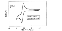
- 238000002484 cyclic voltammetry Methods 0.000 description 16
- 239000000203 mixture Substances 0.000 description 16
- 229910052763 palladium Inorganic materials 0.000 description 16
- 238000005481 NMR spectroscopy Methods 0.000 description 15
- VYPSYNLAJGMNEJ-UHFFFAOYSA-N Silicium dioxide Chemical compound O=[Si]=O VYPSYNLAJGMNEJ-UHFFFAOYSA-N 0.000 description 15
- 239000003054 catalyst Substances 0.000 description 15
- 238000005259 measurement Methods 0.000 description 15
- VLKZOEOYAKHREP-UHFFFAOYSA-N n-Hexane Chemical compound CCCCCC VLKZOEOYAKHREP-UHFFFAOYSA-N 0.000 description 15
- 238000007254 oxidation reaction Methods 0.000 description 15
- GEEJJEAKNZCCMU-UHFFFAOYSA-N n,4-diphenyl-n-[4-(3-phenylquinoxalin-2-yl)phenyl]aniline Chemical compound C1=CC=CC=C1N(C=1C=CC(=CC=1)C=1C(=NC2=CC=CC=C2N=1)C=1C=CC=CC=1)C1=CC=C(C=2C=CC=CC=2)C=C1 GEEJJEAKNZCCMU-UHFFFAOYSA-N 0.000 description 14
- BWHMMNNQKKPAPP-UHFFFAOYSA-L potassium carbonate Chemical compound [K+].[K+].[O-]C([O-])=O BWHMMNNQKKPAPP-UHFFFAOYSA-L 0.000 description 14
- 238000010521 absorption reaction Methods 0.000 description 13
- 239000010949 copper Substances 0.000 description 13
- SIKARGCNKRSUSE-UHFFFAOYSA-N 4-phenyl-n-(4-phenylphenyl)-n-[4-(3-phenylquinoxalin-2-yl)phenyl]aniline Chemical compound C1=CC=CC=C1C1=CC=C(N(C=2C=CC(=CC=2)C=2C=CC=CC=2)C=2C=CC(=CC=2)C=2C(=NC3=CC=CC=C3N=2)C=2C=CC=CC=2)C=C1 SIKARGCNKRSUSE-UHFFFAOYSA-N 0.000 description 12
- RYGMFSIKBFXOCR-UHFFFAOYSA-N Copper Chemical compound [Cu] RYGMFSIKBFXOCR-UHFFFAOYSA-N 0.000 description 12
- YMWUJEATGCHHMB-UHFFFAOYSA-N Dichloromethane Chemical compound ClCCl YMWUJEATGCHHMB-UHFFFAOYSA-N 0.000 description 12
- 229910052802 copper Inorganic materials 0.000 description 12
- PQQKPALAQIIWST-UHFFFAOYSA-N oxomolybdenum Chemical compound [Mo]=O PQQKPALAQIIWST-UHFFFAOYSA-N 0.000 description 12
- CSNNHWWHGAXBCP-UHFFFAOYSA-L Magnesium sulfate Chemical compound [Mg+2].[O-][S+2]([O-])([O-])[O-] CSNNHWWHGAXBCP-UHFFFAOYSA-L 0.000 description 10
- 229910052782 aluminium Inorganic materials 0.000 description 10
- 239000011159 matrix material Substances 0.000 description 10
- 229910000476 molybdenum oxide Inorganic materials 0.000 description 10
- 230000009467 reduction Effects 0.000 description 10
- XLOMVQKBTHCTTD-UHFFFAOYSA-N Zinc monoxide Chemical compound [Zn]=O XLOMVQKBTHCTTD-UHFFFAOYSA-N 0.000 description 9
- MILUBEOXRNEUHS-UHFFFAOYSA-N iridium(3+) Chemical compound [Ir+3] MILUBEOXRNEUHS-UHFFFAOYSA-N 0.000 description 9
- 239000010453 quartz Substances 0.000 description 9
- ZMXDDKWLCZADIW-UHFFFAOYSA-N N,N-Dimethylformamide Chemical class CN(C)C=O ZMXDDKWLCZADIW-UHFFFAOYSA-N 0.000 description 8
- CTQNGGLPUBDAKN-UHFFFAOYSA-N O-Xylene Chemical compound CC1=CC=CC=C1C CTQNGGLPUBDAKN-UHFFFAOYSA-N 0.000 description 8
- 125000005595 acetylacetonate group Chemical group 0.000 description 8
- XAGFODPZIPBFFR-UHFFFAOYSA-N aluminium Chemical compound [Al] XAGFODPZIPBFFR-UHFFFAOYSA-N 0.000 description 8
- 239000000706 filtrate Substances 0.000 description 8
- 239000011521 glass Substances 0.000 description 8
- 239000004973 liquid crystal related substance Substances 0.000 description 8
- 229910052744 lithium Inorganic materials 0.000 description 8
- 229910044991 metal oxide Inorganic materials 0.000 description 8
- 150000004706 metal oxides Chemical class 0.000 description 8
- 239000000843 powder Substances 0.000 description 8
- 229910000029 sodium carbonate Inorganic materials 0.000 description 8
- 239000007787 solid Substances 0.000 description 8
- 239000008096 xylene Substances 0.000 description 8
- WHXSMMKQMYFTQS-UHFFFAOYSA-N Lithium Chemical compound [Li] WHXSMMKQMYFTQS-UHFFFAOYSA-N 0.000 description 7
- 150000004703 alkoxides Chemical class 0.000 description 7
- 230000006866 deterioration Effects 0.000 description 7
- 150000007529 inorganic bases Chemical class 0.000 description 7
- 239000012046 mixed solvent Substances 0.000 description 7
- 229910052757 nitrogen Inorganic materials 0.000 description 7
- 150000007530 organic bases Chemical class 0.000 description 7
- 239000012044 organic layer Substances 0.000 description 7
- 125000002524 organometallic group Chemical group 0.000 description 7
- 230000003647 oxidation Effects 0.000 description 7
- YJVFFLUZDVXJQI-UHFFFAOYSA-L palladium(ii) acetate Chemical compound [Pd+2].CC([O-])=O.CC([O-])=O YJVFFLUZDVXJQI-UHFFFAOYSA-L 0.000 description 7
- 229910052697 platinum Inorganic materials 0.000 description 7
- 229910000027 potassium carbonate Inorganic materials 0.000 description 7
- 238000004544 sputter deposition Methods 0.000 description 7
- XKRFYHLGVUSROY-UHFFFAOYSA-N Argon Chemical compound [Ar] XKRFYHLGVUSROY-UHFFFAOYSA-N 0.000 description 6
- XTHFKEDIFFGKHM-UHFFFAOYSA-N Dimethoxyethane Chemical compound COCCOC XTHFKEDIFFGKHM-UHFFFAOYSA-N 0.000 description 6
- 150000004982 aromatic amines Chemical class 0.000 description 6
- 150000004945 aromatic hydrocarbons Chemical class 0.000 description 6
- 230000008859 change Effects 0.000 description 6
- 238000010438 heat treatment Methods 0.000 description 6
- 229910003437 indium oxide Inorganic materials 0.000 description 6
- PJXISJQVUVHSOJ-UHFFFAOYSA-N indium(iii) oxide Chemical compound [O-2].[O-2].[O-2].[In+3].[In+3] PJXISJQVUVHSOJ-UHFFFAOYSA-N 0.000 description 6
- 239000012212 insulator Substances 0.000 description 6
- QGLKJKCYBOYXKC-UHFFFAOYSA-N nonaoxidotritungsten Chemical compound O=[W]1(=O)O[W](=O)(=O)O[W](=O)(=O)O1 QGLKJKCYBOYXKC-UHFFFAOYSA-N 0.000 description 6
- NFHFRUOZVGFOOS-UHFFFAOYSA-N palladium;triphenylphosphane Chemical compound [Pd].C1=CC=CC=C1P(C=1C=CC=CC=1)C1=CC=CC=C1.C1=CC=CC=C1P(C=1C=CC=CC=1)C1=CC=CC=C1.C1=CC=CC=C1P(C=1C=CC=CC=1)C1=CC=CC=C1.C1=CC=CC=C1P(C=1C=CC=CC=1)C1=CC=CC=C1 NFHFRUOZVGFOOS-UHFFFAOYSA-N 0.000 description 6
- 230000007704 transition Effects 0.000 description 6
- 229910001930 tungsten oxide Inorganic materials 0.000 description 6
- 238000007740 vapor deposition Methods 0.000 description 6
- UKSZBOKPHAQOMP-SVLSSHOZSA-N (1e,4e)-1,5-diphenylpenta-1,4-dien-3-one;palladium Chemical compound [Pd].C=1C=CC=CC=1\C=C\C(=O)\C=C\C1=CC=CC=C1.C=1C=CC=CC=1\C=C\C(=O)\C=C\C1=CC=CC=C1 UKSZBOKPHAQOMP-SVLSSHOZSA-N 0.000 description 5
- NRTOMJZYCJJWKI-UHFFFAOYSA-N Titanium nitride Chemical compound [Ti]#N NRTOMJZYCJJWKI-UHFFFAOYSA-N 0.000 description 5
- 229910045601 alloy Inorganic materials 0.000 description 5
- 239000000956 alloy Substances 0.000 description 5
- 150000001412 amines Chemical group 0.000 description 5
- 230000001413 cellular effect Effects 0.000 description 5
- 238000006243 chemical reaction Methods 0.000 description 5
- 230000008878 coupling Effects 0.000 description 5
- 238000010168 coupling process Methods 0.000 description 5
- 238000005859 coupling reaction Methods 0.000 description 5
- 229910052736 halogen Inorganic materials 0.000 description 5
- 150000002367 halogens Chemical class 0.000 description 5
- 230000003993 interaction Effects 0.000 description 5
- 239000011777 magnesium Substances 0.000 description 5
- 229910052943 magnesium sulfate Inorganic materials 0.000 description 5
- 235000019341 magnesium sulphate Nutrition 0.000 description 5
- 150000002736 metal compounds Chemical class 0.000 description 5
- IBHBKWKFFTZAHE-UHFFFAOYSA-N n-[4-[4-(n-naphthalen-1-ylanilino)phenyl]phenyl]-n-phenylnaphthalen-1-amine Chemical group C1=CC=CC=C1N(C=1C2=CC=CC=C2C=CC=1)C1=CC=C(C=2C=CC(=CC=2)N(C=2C=CC=CC=2)C=2C3=CC=CC=C3C=CC=2)C=C1 IBHBKWKFFTZAHE-UHFFFAOYSA-N 0.000 description 5
- LXNAVEXFUKBNMK-UHFFFAOYSA-N palladium(II) acetate Substances [Pd].CC(O)=O.CC(O)=O LXNAVEXFUKBNMK-UHFFFAOYSA-N 0.000 description 5
- 238000005192 partition Methods 0.000 description 5
- 238000007789 sealing Methods 0.000 description 5
- 239000004065 semiconductor Substances 0.000 description 5
- 230000002194 synthesizing effect Effects 0.000 description 5
- AZFHXIBNMPIGOD-UHFFFAOYSA-N 4-hydroxypent-3-en-2-one iridium Chemical compound [Ir].CC(O)=CC(C)=O.CC(O)=CC(C)=O.CC(O)=CC(C)=O AZFHXIBNMPIGOD-UHFFFAOYSA-N 0.000 description 4
- VFUDMQLBKNMONU-UHFFFAOYSA-N 9-[4-(4-carbazol-9-ylphenyl)phenyl]carbazole Chemical group C12=CC=CC=C2C2=CC=CC=C2N1C1=CC=C(C=2C=CC(=CC=2)N2C3=CC=CC=C3C3=CC=CC=C32)C=C1 VFUDMQLBKNMONU-UHFFFAOYSA-N 0.000 description 4
- IJGRMHOSHXDMSA-UHFFFAOYSA-N Atomic nitrogen Chemical compound N#N IJGRMHOSHXDMSA-UHFFFAOYSA-N 0.000 description 4
- HEDRZPFGACZZDS-UHFFFAOYSA-N Chloroform Chemical compound ClC(Cl)Cl HEDRZPFGACZZDS-UHFFFAOYSA-N 0.000 description 4
- UIIMBOGNXHQVGW-UHFFFAOYSA-M Sodium bicarbonate Chemical compound [Na+].OC([O-])=O UIIMBOGNXHQVGW-UHFFFAOYSA-M 0.000 description 4
- AZWHFTKIBIQKCA-UHFFFAOYSA-N [Sn+2]=O.[O-2].[In+3] Chemical compound [Sn+2]=O.[O-2].[In+3] AZWHFTKIBIQKCA-UHFFFAOYSA-N 0.000 description 4
- 229910052783 alkali metal Inorganic materials 0.000 description 4
- 150000001340 alkali metals Chemical class 0.000 description 4
- 229910052784 alkaline earth metal Inorganic materials 0.000 description 4
- 150000001342 alkaline earth metals Chemical class 0.000 description 4
- XJHCXCQVJFPJIK-UHFFFAOYSA-M caesium fluoride Chemical compound [F-].[Cs+] XJHCXCQVJFPJIK-UHFFFAOYSA-M 0.000 description 4
- 150000001716 carbazoles Chemical class 0.000 description 4
- 239000000460 chlorine Substances 0.000 description 4
- 239000003086 colorant Substances 0.000 description 4
- ZUOUZKKEUPVFJK-UHFFFAOYSA-N diphenyl Chemical group C1=CC=CC=C1C1=CC=CC=C1 ZUOUZKKEUPVFJK-UHFFFAOYSA-N 0.000 description 4
- 238000001704 evaporation Methods 0.000 description 4
- 230000005281 excited state Effects 0.000 description 4
- 238000004770 highest occupied molecular orbital Methods 0.000 description 4
- AMWRITDGCCNYAT-UHFFFAOYSA-L hydroxy(oxo)manganese;manganese Chemical compound [Mn].O[Mn]=O.O[Mn]=O AMWRITDGCCNYAT-UHFFFAOYSA-L 0.000 description 4
- 238000004519 manufacturing process Methods 0.000 description 4
- 239000012299 nitrogen atmosphere Substances 0.000 description 4
- HXITXNWTGFUOAU-UHFFFAOYSA-N phenylboronic acid Chemical group OB(O)C1=CC=CC=C1 HXITXNWTGFUOAU-UHFFFAOYSA-N 0.000 description 4
- 229920003023 plastic Polymers 0.000 description 4
- 239000004033 plastic Substances 0.000 description 4
- 229920003227 poly(N-vinyl carbazole) Polymers 0.000 description 4
- 239000000047 product Substances 0.000 description 4
- 238000000746 purification Methods 0.000 description 4
- 238000006479 redox reaction Methods 0.000 description 4
- 239000000565 sealant Substances 0.000 description 4
- 229910052710 silicon Inorganic materials 0.000 description 4
- 239000010703 silicon Substances 0.000 description 4
- 229910052814 silicon oxide Inorganic materials 0.000 description 4
- MFRIHAYPQRLWNB-UHFFFAOYSA-N sodium tert-butoxide Chemical compound [Na+].CC(C)(C)[O-] MFRIHAYPQRLWNB-UHFFFAOYSA-N 0.000 description 4
- 238000000859 sublimation Methods 0.000 description 4
- 230000008022 sublimation Effects 0.000 description 4
- KBLZDCFTQSIIOH-UHFFFAOYSA-M tetrabutylazanium;perchlorate Chemical compound [O-]Cl(=O)(=O)=O.CCCC[N+](CCCC)(CCCC)CCCC KBLZDCFTQSIIOH-UHFFFAOYSA-M 0.000 description 4
- 238000000870 ultraviolet spectroscopy Methods 0.000 description 4
- XLYOFNOQVPJJNP-UHFFFAOYSA-N water Chemical compound O XLYOFNOQVPJJNP-UHFFFAOYSA-N 0.000 description 4
- 239000011701 zinc Substances 0.000 description 4
- 239000011787 zinc oxide Substances 0.000 description 4
- LZDKZFUFMNSQCJ-UHFFFAOYSA-N 1,2-diethoxyethane Chemical compound CCOCCOCC LZDKZFUFMNSQCJ-UHFFFAOYSA-N 0.000 description 3
- OCQQXLPLQWPKFG-UHFFFAOYSA-N 2,3,5-triphenylpyrazine Chemical compound C1=CC=CC=C1C(N=C1C=2C=CC=CC=2)=CN=C1C1=CC=CC=C1 OCQQXLPLQWPKFG-UHFFFAOYSA-N 0.000 description 3
- AJUHJMMNWVKCER-UHFFFAOYSA-N 2-(2-phenylphenyl)aniline Chemical compound NC1=CC=CC=C1C1=CC=CC=C1C1=CC=CC=C1 AJUHJMMNWVKCER-UHFFFAOYSA-N 0.000 description 3
- OLJCVZUGBZYQOD-UHFFFAOYSA-N 2-(4-bromophenyl)-3-phenylquinoxaline Chemical compound C1=CC(Br)=CC=C1C1=NC2=CC=CC=C2N=C1C1=CC=CC=C1 OLJCVZUGBZYQOD-UHFFFAOYSA-N 0.000 description 3
- PXHVJJICTQNCMI-UHFFFAOYSA-N Nickel Chemical compound [Ni] PXHVJJICTQNCMI-UHFFFAOYSA-N 0.000 description 3
- 239000007983 Tris buffer Substances 0.000 description 3
- XHCLAFWTIXFWPH-UHFFFAOYSA-N [O-2].[O-2].[O-2].[O-2].[O-2].[V+5].[V+5] Chemical compound [O-2].[O-2].[O-2].[O-2].[O-2].[V+5].[V+5] XHCLAFWTIXFWPH-UHFFFAOYSA-N 0.000 description 3
- 229910052786 argon Inorganic materials 0.000 description 3
- UFVXQDWNSAGPHN-UHFFFAOYSA-K bis[(2-methylquinolin-8-yl)oxy]-(4-phenylphenoxy)alumane Chemical compound [Al+3].C1=CC=C([O-])C2=NC(C)=CC=C21.C1=CC=C([O-])C2=NC(C)=CC=C21.C1=CC([O-])=CC=C1C1=CC=CC=C1 UFVXQDWNSAGPHN-UHFFFAOYSA-K 0.000 description 3
- 239000011575 calcium Substances 0.000 description 3
- 239000011651 chromium Substances 0.000 description 3
- 230000000295 complement effect Effects 0.000 description 3
- 239000000412 dendrimer Substances 0.000 description 3
- 229920000736 dendritic polymer Polymers 0.000 description 3
- 238000011161 development Methods 0.000 description 3
- 230000002349 favourable effect Effects 0.000 description 3
- AMGQUBHHOARCQH-UHFFFAOYSA-N indium;oxotin Chemical compound [In].[Sn]=O AMGQUBHHOARCQH-UHFFFAOYSA-N 0.000 description 3
- PQXKHYXIUOZZFA-UHFFFAOYSA-M lithium fluoride Chemical compound [Li+].[F-] PQXKHYXIUOZZFA-UHFFFAOYSA-M 0.000 description 3
- 229910052749 magnesium Inorganic materials 0.000 description 3
- 125000004108 n-butyl group Chemical group [H]C([H])([H])C([H])([H])C([H])([H])C([H])([H])* 0.000 description 3
- 230000003287 optical effect Effects 0.000 description 3
- OJUGVDODNPJEEC-UHFFFAOYSA-N phenylglyoxal Chemical compound O=CC(=O)C1=CC=CC=C1 OJUGVDODNPJEEC-UHFFFAOYSA-N 0.000 description 3
- 229920000642 polymer Polymers 0.000 description 3
- 150000003216 pyrazines Chemical class 0.000 description 3
- 238000010791 quenching Methods 0.000 description 3
- 230000000171 quenching effect Effects 0.000 description 3
- 239000003566 sealing material Substances 0.000 description 3
- 239000002356 single layer Substances 0.000 description 3
- 238000004528 spin coating Methods 0.000 description 3
- 125000001424 substituent group Chemical group 0.000 description 3
- TVIVIEFSHFOWTE-UHFFFAOYSA-K tri(quinolin-8-yloxy)alumane Chemical compound [Al+3].C1=CN=C2C([O-])=CC=CC2=C1.C1=CN=C2C([O-])=CC=CC2=C1.C1=CN=C2C([O-])=CC=CC2=C1 TVIVIEFSHFOWTE-UHFFFAOYSA-K 0.000 description 3
- 229910001935 vanadium oxide Inorganic materials 0.000 description 3
- UHXOHPVVEHBKKT-UHFFFAOYSA-N 1-(2,2-diphenylethenyl)-4-[4-(2,2-diphenylethenyl)phenyl]benzene Chemical group C=1C=C(C=2C=CC(C=C(C=3C=CC=CC=3)C=3C=CC=CC=3)=CC=2)C=CC=1C=C(C=1C=CC=CC=1)C1=CC=CC=C1 UHXOHPVVEHBKKT-UHFFFAOYSA-N 0.000 description 2
- XOYZGLGJSAZOAG-UHFFFAOYSA-N 1-n,1-n,4-n-triphenyl-4-n-[4-[4-(n-[4-(n-phenylanilino)phenyl]anilino)phenyl]phenyl]benzene-1,4-diamine Chemical group C1=CC=CC=C1N(C=1C=CC(=CC=1)N(C=1C=CC=CC=1)C=1C=CC(=CC=1)C=1C=CC(=CC=1)N(C=1C=CC=CC=1)C=1C=CC(=CC=1)N(C=1C=CC=CC=1)C=1C=CC=CC=1)C1=CC=CC=C1 XOYZGLGJSAZOAG-UHFFFAOYSA-N 0.000 description 2
- IYZMXHQDXZKNCY-UHFFFAOYSA-N 1-n,1-n-diphenyl-4-n,4-n-bis[4-(n-phenylanilino)phenyl]benzene-1,4-diamine Chemical compound C1=CC=CC=C1N(C=1C=CC(=CC=1)N(C=1C=CC(=CC=1)N(C=1C=CC=CC=1)C=1C=CC=CC=1)C=1C=CC(=CC=1)N(C=1C=CC=CC=1)C=1C=CC=CC=1)C1=CC=CC=C1 IYZMXHQDXZKNCY-UHFFFAOYSA-N 0.000 description 2
- SPDPTFAJSFKAMT-UHFFFAOYSA-N 1-n-[4-[4-(n-[4-(3-methyl-n-(3-methylphenyl)anilino)phenyl]anilino)phenyl]phenyl]-4-n,4-n-bis(3-methylphenyl)-1-n-phenylbenzene-1,4-diamine Chemical compound CC1=CC=CC(N(C=2C=CC(=CC=2)N(C=2C=CC=CC=2)C=2C=CC(=CC=2)C=2C=CC(=CC=2)N(C=2C=CC=CC=2)C=2C=CC(=CC=2)N(C=2C=C(C)C=CC=2)C=2C=C(C)C=CC=2)C=2C=C(C)C=CC=2)=C1 SPDPTFAJSFKAMT-UHFFFAOYSA-N 0.000 description 2
- 238000005160 1H NMR spectroscopy Methods 0.000 description 2
- YLYPIBBGWLKELC-RMKNXTFCSA-N 2-[2-[(e)-2-[4-(dimethylamino)phenyl]ethenyl]-6-methylpyran-4-ylidene]propanedinitrile Chemical compound C1=CC(N(C)C)=CC=C1\C=C\C1=CC(=C(C#N)C#N)C=C(C)O1 YLYPIBBGWLKELC-RMKNXTFCSA-N 0.000 description 2
- GEQBRULPNIVQPP-UHFFFAOYSA-N 2-[3,5-bis(1-phenylbenzimidazol-2-yl)phenyl]-1-phenylbenzimidazole Chemical compound C1=CC=CC=C1N1C2=CC=CC=C2N=C1C1=CC(C=2N(C3=CC=CC=C3N=2)C=2C=CC=CC=2)=CC(C=2N(C3=CC=CC=C3N=2)C=2C=CC=CC=2)=C1 GEQBRULPNIVQPP-UHFFFAOYSA-N 0.000 description 2
- ZNQVEEAIQZEUHB-UHFFFAOYSA-N 2-ethoxyethanol Chemical compound CCOCCO ZNQVEEAIQZEUHB-UHFFFAOYSA-N 0.000 description 2
- 229940093475 2-ethoxyethanol Drugs 0.000 description 2
- OBAJPWYDYFEBTF-UHFFFAOYSA-N 2-tert-butyl-9,10-dinaphthalen-2-ylanthracene Chemical compound C1=CC=CC2=CC(C3=C4C=CC=CC4=C(C=4C=C5C=CC=CC5=CC=4)C4=CC=C(C=C43)C(C)(C)C)=CC=C21 OBAJPWYDYFEBTF-UHFFFAOYSA-N 0.000 description 2
- ZVFQEOPUXVPSLB-UHFFFAOYSA-N 3-(4-tert-butylphenyl)-4-phenyl-5-(4-phenylphenyl)-1,2,4-triazole Chemical compound C1=CC(C(C)(C)C)=CC=C1C(N1C=2C=CC=CC=2)=NN=C1C1=CC=C(C=2C=CC=CC=2)C=C1 ZVFQEOPUXVPSLB-UHFFFAOYSA-N 0.000 description 2
- DHDHJYNTEFLIHY-UHFFFAOYSA-N 4,7-diphenyl-1,10-phenanthroline Chemical compound C1=CC=CC=C1C1=CC=NC2=C1C=CC1=C(C=3C=CC=CC=3)C=CN=C21 DHDHJYNTEFLIHY-UHFFFAOYSA-N 0.000 description 2
- 125000001255 4-fluorophenyl group Chemical group [H]C1=C([H])C(*)=C([H])C([H])=C1F 0.000 description 2
- QYNTUCBQEHUHCS-UHFFFAOYSA-N 4-n-(3-methylphenyl)-1-n-[4-[4-(n-[4-(n-(3-methylphenyl)anilino)phenyl]anilino)phenyl]phenyl]-1-n,4-n-diphenylbenzene-1,4-diamine Chemical group CC1=CC=CC(N(C=2C=CC=CC=2)C=2C=CC(=CC=2)N(C=2C=CC=CC=2)C=2C=CC(=CC=2)C=2C=CC(=CC=2)N(C=2C=CC=CC=2)C=2C=CC(=CC=2)N(C=2C=CC=CC=2)C=2C=C(C)C=CC=2)=C1 QYNTUCBQEHUHCS-UHFFFAOYSA-N 0.000 description 2
- JAUCIDPGGHZXRP-UHFFFAOYSA-N 4-phenyl-n-(4-phenylphenyl)aniline Chemical compound C=1C=C(C=2C=CC=CC=2)C=CC=1NC(C=C1)=CC=C1C1=CC=CC=C1 JAUCIDPGGHZXRP-UHFFFAOYSA-N 0.000 description 2
- VIZUPBYFLORCRA-UHFFFAOYSA-N 9,10-dinaphthalen-2-ylanthracene Chemical compound C12=CC=CC=C2C(C2=CC3=CC=CC=C3C=C2)=C(C=CC=C2)C2=C1C1=CC=C(C=CC=C2)C2=C1 VIZUPBYFLORCRA-UHFFFAOYSA-N 0.000 description 2
- FCNCGHJSNVOIKE-UHFFFAOYSA-N 9,10-diphenylanthracene Chemical compound C1=CC=CC=C1C(C1=CC=CC=C11)=C(C=CC=C2)C2=C1C1=CC=CC=C1 FCNCGHJSNVOIKE-UHFFFAOYSA-N 0.000 description 2
- 229910017073 AlLi Inorganic materials 0.000 description 2
- WKBOTKDWSSQWDR-UHFFFAOYSA-N Bromine atom Chemical compound [Br] WKBOTKDWSSQWDR-UHFFFAOYSA-N 0.000 description 2
- 0 C*(c(cc1)ccc1-c1ccccc1)c(cc1)ccc1-c1ccccc1-c1ccccc1 Chemical compound C*(c(cc1)ccc1-c1ccccc1)c(cc1)ccc1-c1ccccc1-c1ccccc1 0.000 description 2
- VYZAMTAEIAYCRO-UHFFFAOYSA-N Chromium Chemical compound [Cr] VYZAMTAEIAYCRO-UHFFFAOYSA-N 0.000 description 2
- FYYHWMGAXLPEAU-UHFFFAOYSA-N Magnesium Chemical compound [Mg] FYYHWMGAXLPEAU-UHFFFAOYSA-N 0.000 description 2
- PAYRUJLWNCNPSJ-UHFFFAOYSA-N N-phenyl amine Natural products NC1=CC=CC=C1 PAYRUJLWNCNPSJ-UHFFFAOYSA-N 0.000 description 2
- PHXQIAWFIIMOKG-UHFFFAOYSA-N NClO Chemical compound NClO PHXQIAWFIIMOKG-UHFFFAOYSA-N 0.000 description 2
- 229920001609 Poly(3,4-ethylenedioxythiophene) Polymers 0.000 description 2
- HCHKCACWOHOZIP-UHFFFAOYSA-N Zinc Chemical compound [Zn] HCHKCACWOHOZIP-UHFFFAOYSA-N 0.000 description 2
- YRKCREAYFQTBPV-UHFFFAOYSA-N acetylacetone Chemical compound CC(=O)CC(C)=O YRKCREAYFQTBPV-UHFFFAOYSA-N 0.000 description 2
- NIXOWILDQLNWCW-UHFFFAOYSA-N acrylic acid group Chemical group C(C=C)(=O)O NIXOWILDQLNWCW-UHFFFAOYSA-N 0.000 description 2
- PNEYBMLMFCGWSK-UHFFFAOYSA-N aluminium oxide Inorganic materials [O-2].[O-2].[O-2].[Al+3].[Al+3] PNEYBMLMFCGWSK-UHFFFAOYSA-N 0.000 description 2
- 125000003277 amino group Chemical group 0.000 description 2
- MWPLVEDNUUSJAV-UHFFFAOYSA-N anthracene Chemical compound C1=CC=CC2=CC3=CC=CC=C3C=C21 MWPLVEDNUUSJAV-UHFFFAOYSA-N 0.000 description 2
- 239000003125 aqueous solvent Substances 0.000 description 2
- 239000012298 atmosphere Substances 0.000 description 2
- 230000008901 benefit Effects 0.000 description 2
- DMVOXQPQNTYEKQ-UHFFFAOYSA-N biphenyl-4-amine Chemical group C1=CC(N)=CC=C1C1=CC=CC=C1 DMVOXQPQNTYEKQ-UHFFFAOYSA-N 0.000 description 2
- GDTBXPJZTBHREO-UHFFFAOYSA-N bromine Substances BrBr GDTBXPJZTBHREO-UHFFFAOYSA-N 0.000 description 2
- 229910052794 bromium Inorganic materials 0.000 description 2
- 229910052791 calcium Inorganic materials 0.000 description 2
- 239000000969 carrier Substances 0.000 description 2
- 229910052804 chromium Inorganic materials 0.000 description 2
- 238000010549 co-Evaporation Methods 0.000 description 2
- 239000004020 conductor Substances 0.000 description 2
- 150000004696 coordination complex Chemical class 0.000 description 2
- VPUGDVKSAQVFFS-UHFFFAOYSA-N coronene Chemical compound C1=C(C2=C34)C=CC3=CC=C(C=C3)C4=C4C3=CC=C(C=C3)C4=C2C3=C1 VPUGDVKSAQVFFS-UHFFFAOYSA-N 0.000 description 2
- 230000007547 defect Effects 0.000 description 2
- 238000000151 deposition Methods 0.000 description 2
- 125000005266 diarylamine group Chemical group 0.000 description 2
- DMBHHRLKUKUOEG-UHFFFAOYSA-N diphenylamine Chemical compound C=1C=CC=CC=1NC1=CC=CC=C1 DMBHHRLKUKUOEG-UHFFFAOYSA-N 0.000 description 2
- 230000005611 electricity Effects 0.000 description 2
- 238000006056 electrooxidation reaction Methods 0.000 description 2
- 239000011152 fibreglass Substances 0.000 description 2
- 239000010931 gold Substances 0.000 description 2
- 125000005843 halogen group Chemical group 0.000 description 2
- 238000005286 illumination Methods 0.000 description 2
- 229910010272 inorganic material Inorganic materials 0.000 description 2
- 229910052741 iridium Inorganic materials 0.000 description 2
- GKOZUEZYRPOHIO-UHFFFAOYSA-N iridium atom Chemical compound [Ir] GKOZUEZYRPOHIO-UHFFFAOYSA-N 0.000 description 2
- 238000004768 lowest unoccupied molecular orbital Methods 0.000 description 2
- NUJOXMJBOLGQSY-UHFFFAOYSA-N manganese dioxide Chemical compound O=[Mn]=O NUJOXMJBOLGQSY-UHFFFAOYSA-N 0.000 description 2
- 230000007246 mechanism Effects 0.000 description 2
- 239000007769 metal material Substances 0.000 description 2
- YGNUPJXMDOFFDO-UHFFFAOYSA-N n,4-diphenylaniline Chemical compound C=1C=C(C=2C=CC=CC=2)C=CC=1NC1=CC=CC=C1 YGNUPJXMDOFFDO-UHFFFAOYSA-N 0.000 description 2
- QJGQUHMNIGDVPM-UHFFFAOYSA-N nitrogen group Chemical group [N] QJGQUHMNIGDVPM-UHFFFAOYSA-N 0.000 description 2
- 239000011368 organic material Substances 0.000 description 2
- AHLBNYSZXLDEJQ-FWEHEUNISA-N orlistat Chemical compound CCCCCCCCCCC[C@H](OC(=O)[C@H](CC(C)C)NC=O)C[C@@H]1OC(=O)[C@H]1CCCCCC AHLBNYSZXLDEJQ-FWEHEUNISA-N 0.000 description 2
- 230000033116 oxidation-reduction process Effects 0.000 description 2
- 230000000737 periodic effect Effects 0.000 description 2
- 125000002080 perylenyl group Chemical group C1(=CC=C2C=CC=C3C4=CC=CC5=CC=CC(C1=C23)=C45)* 0.000 description 2
- CSHWQDPOILHKBI-UHFFFAOYSA-N peryrene Natural products C1=CC(C2=CC=CC=3C2=C2C=CC=3)=C3C2=CC=CC3=C1 CSHWQDPOILHKBI-UHFFFAOYSA-N 0.000 description 2
- 238000001420 photoelectron spectroscopy Methods 0.000 description 2
- IEQIEDJGQAUEQZ-UHFFFAOYSA-N phthalocyanine Chemical class N1C(N=C2C3=CC=CC=C3C(N=C3C4=CC=CC=C4C(=N4)N3)=N2)=C(C=CC=C2)C2=C1N=C1C2=CC=CC=C2C4=N1 IEQIEDJGQAUEQZ-UHFFFAOYSA-N 0.000 description 2
- 229920000078 poly(4-vinyltriphenylamine) Polymers 0.000 description 2
- 229920002620 polyvinyl fluoride Polymers 0.000 description 2
- 239000011541 reaction mixture Substances 0.000 description 2
- 238000011084 recovery Methods 0.000 description 2
- 238000001953 recrystallisation Methods 0.000 description 2
- 238000010992 reflux Methods 0.000 description 2
- YYMBJDOZVAITBP-UHFFFAOYSA-N rubrene Chemical compound C1=CC=CC=C1C(C1=C(C=2C=CC=CC=2)C2=CC=CC=C2C(C=2C=CC=CC=2)=C11)=C(C=CC=C2)C2=C1C1=CC=CC=C1 YYMBJDOZVAITBP-UHFFFAOYSA-N 0.000 description 2
- 229920006395 saturated elastomer Polymers 0.000 description 2
- 238000000926 separation method Methods 0.000 description 2
- 229910000030 sodium bicarbonate Inorganic materials 0.000 description 2
- 235000017557 sodium bicarbonate Nutrition 0.000 description 2
- HPALAKNZSZLMCH-UHFFFAOYSA-M sodium;chloride;hydrate Chemical class O.[Na+].[Cl-] HPALAKNZSZLMCH-UHFFFAOYSA-M 0.000 description 2
- 238000003980 solgel method Methods 0.000 description 2
- 238000003756 stirring Methods 0.000 description 2
- 238000005092 sublimation method Methods 0.000 description 2
- 238000006467 substitution reaction Methods 0.000 description 2
- 239000003115 supporting electrolyte Substances 0.000 description 2
- 239000000725 suspension Substances 0.000 description 2
- 238000001308 synthesis method Methods 0.000 description 2
- FKHIFSZMMVMEQY-UHFFFAOYSA-N talc Chemical compound [Mg+2].[O-][Si]([O-])=O FKHIFSZMMVMEQY-UHFFFAOYSA-N 0.000 description 2
- BWHDROKFUHTORW-UHFFFAOYSA-N tritert-butylphosphane Chemical compound CC(C)(C)P(C(C)(C)C)C(C)(C)C BWHDROKFUHTORW-UHFFFAOYSA-N 0.000 description 2
- WFKWXMTUELFFGS-UHFFFAOYSA-N tungsten Chemical compound [W] WFKWXMTUELFFGS-UHFFFAOYSA-N 0.000 description 2
- 229910052721 tungsten Inorganic materials 0.000 description 2
- 239000010937 tungsten Substances 0.000 description 2
- 238000001771 vacuum deposition Methods 0.000 description 2
- 238000007738 vacuum evaporation Methods 0.000 description 2
- 125000000391 vinyl group Chemical group [H]C([*])=C([H])[H] 0.000 description 2
- 229910052725 zinc Inorganic materials 0.000 description 2
- PONXTPCRRASWKW-OKILXGFUSA-N (1r,2s)-1,2-diphenylethane-1,2-diamine Chemical compound C1([C@H](N)[C@H](N)C=2C=CC=CC=2)=CC=CC=C1 PONXTPCRRASWKW-OKILXGFUSA-N 0.000 description 1
- 125000004178 (C1-C4) alkyl group Chemical group 0.000 description 1
- RTSZQXSYCGBHMO-UHFFFAOYSA-N 1,2,4-trichloro-3-prop-1-ynoxybenzene Chemical compound CC#COC1=C(Cl)C=CC(Cl)=C1Cl RTSZQXSYCGBHMO-UHFFFAOYSA-N 0.000 description 1
- GEYOCULIXLDCMW-UHFFFAOYSA-N 1,2-phenylenediamine Chemical class NC1=CC=CC=C1N GEYOCULIXLDCMW-UHFFFAOYSA-N 0.000 description 1
- WMKGGPCROCCUDY-UHFFFAOYSA-N 1,5-diphenylpenta-1,4-dien-3-one Chemical compound C=1C=CC=CC=1C=CC(=O)C=CC1=CC=CC=C1 WMKGGPCROCCUDY-UHFFFAOYSA-N 0.000 description 1
- FQNVFRPAQRVHKO-UHFFFAOYSA-N 1-n,4-n-bis(4-methylphenyl)-1-n,4-n-diphenylbenzene-1,4-diamine Chemical compound C1=CC(C)=CC=C1N(C=1C=CC(=CC=1)N(C=1C=CC=CC=1)C=1C=CC(C)=CC=1)C1=CC=CC=C1 FQNVFRPAQRVHKO-UHFFFAOYSA-N 0.000 description 1
- VOIVTTPPKHORBL-UHFFFAOYSA-N 1-naphthalen-1-ylanthracene Chemical compound C1=CC=C2C(C=3C4=CC5=CC=CC=C5C=C4C=CC=3)=CC=CC2=C1 VOIVTTPPKHORBL-UHFFFAOYSA-N 0.000 description 1
- OOWLPGTVRWFLCX-UHFFFAOYSA-N 2,3,6,7-tetramethyl-9,10-dinaphthalen-1-ylanthracene Chemical compound C1=CC=C2C(C=3C4=CC(C)=C(C)C=C4C(C=4C5=CC=CC=C5C=CC=4)=C4C=C(C(=CC4=3)C)C)=CC=CC2=C1 OOWLPGTVRWFLCX-UHFFFAOYSA-N 0.000 description 1
- JEBPFDQAOYARIB-UHFFFAOYSA-N 2,3,6,7-tetramethyl-9,10-dinaphthalen-2-ylanthracene Chemical compound C1=CC=CC2=CC(C=3C4=CC(C)=C(C)C=C4C(C=4C=C5C=CC=CC5=CC=4)=C4C=C(C(=CC4=3)C)C)=CC=C21 JEBPFDQAOYARIB-UHFFFAOYSA-N 0.000 description 1
- PTZIVVDMBCVSMR-UHFFFAOYSA-N 2,3-diphenylpyrazine Chemical compound C1=CC=CC=C1C1=NC=CN=C1C1=CC=CC=C1 PTZIVVDMBCVSMR-UHFFFAOYSA-N 0.000 description 1
- BFTIPCRZWILUIY-UHFFFAOYSA-N 2,5,8,11-tetratert-butylperylene Chemical group CC(C)(C)C1=CC(C2=CC(C(C)(C)C)=CC=3C2=C2C=C(C=3)C(C)(C)C)=C3C2=CC(C(C)(C)C)=CC3=C1 BFTIPCRZWILUIY-UHFFFAOYSA-N 0.000 description 1
- STTGYIUESPWXOW-UHFFFAOYSA-N 2,9-dimethyl-4,7-diphenyl-1,10-phenanthroline Chemical compound C=12C=CC3=C(C=4C=CC=CC=4)C=C(C)N=C3C2=NC(C)=CC=1C1=CC=CC=C1 STTGYIUESPWXOW-UHFFFAOYSA-N 0.000 description 1
- UOCMXZLNHQBBOS-UHFFFAOYSA-N 2-(1,3-benzoxazol-2-yl)phenol zinc Chemical compound [Zn].Oc1ccccc1-c1nc2ccccc2o1.Oc1ccccc1-c1nc2ccccc2o1 UOCMXZLNHQBBOS-UHFFFAOYSA-N 0.000 description 1
- FQJQNLKWTRGIEB-UHFFFAOYSA-N 2-(4-tert-butylphenyl)-5-[3-[5-(4-tert-butylphenyl)-1,3,4-oxadiazol-2-yl]phenyl]-1,3,4-oxadiazole Chemical compound C1=CC(C(C)(C)C)=CC=C1C1=NN=C(C=2C=C(C=CC=2)C=2OC(=NN=2)C=2C=CC(=CC=2)C(C)(C)C)O1 FQJQNLKWTRGIEB-UHFFFAOYSA-N 0.000 description 1
- IXHWGNYCZPISET-UHFFFAOYSA-N 2-[4-(dicyanomethylidene)-2,3,5,6-tetrafluorocyclohexa-2,5-dien-1-ylidene]propanedinitrile Chemical compound FC1=C(F)C(=C(C#N)C#N)C(F)=C(F)C1=C(C#N)C#N IXHWGNYCZPISET-UHFFFAOYSA-N 0.000 description 1
- POXIZPBFFUKMEQ-UHFFFAOYSA-N 2-cyanoethenylideneazanide Chemical group [N-]=C=[C+]C#N POXIZPBFFUKMEQ-UHFFFAOYSA-N 0.000 description 1
- HONWGFNQCPRRFM-UHFFFAOYSA-N 2-n-(3-methylphenyl)-1-n,1-n,2-n-triphenylbenzene-1,2-diamine Chemical compound CC1=CC=CC(N(C=2C=CC=CC=2)C=2C(=CC=CC=2)N(C=2C=CC=CC=2)C=2C=CC=CC=2)=C1 HONWGFNQCPRRFM-UHFFFAOYSA-N 0.000 description 1
- MNHPNCZSKTUPMB-UHFFFAOYSA-N 2-tert-butyl-9,10-bis(4-phenylphenyl)anthracene Chemical compound C=12C=CC=CC2=C(C=2C=CC(=CC=2)C=2C=CC=CC=2)C2=CC(C(C)(C)C)=CC=C2C=1C(C=C1)=CC=C1C1=CC=CC=C1 MNHPNCZSKTUPMB-UHFFFAOYSA-N 0.000 description 1
- WBPXZSIKOVBSAS-UHFFFAOYSA-N 2-tert-butylanthracene Chemical compound C1=CC=CC2=CC3=CC(C(C)(C)C)=CC=C3C=C21 WBPXZSIKOVBSAS-UHFFFAOYSA-N 0.000 description 1
- TVMBOHMLKCZFFW-UHFFFAOYSA-N 3-N,6-N,9-triphenyl-3-N,6-N-bis(9-phenylcarbazol-3-yl)carbazole-3,6-diamine Chemical compound C1=CC=CC=C1N(C=1C=C2C3=CC(=CC=C3N(C=3C=CC=CC=3)C2=CC=1)N(C=1C=CC=CC=1)C=1C=C2C3=CC=CC=C3N(C=3C=CC=CC=3)C2=CC=1)C1=CC=C(N(C=2C=CC=CC=2)C=2C3=CC=CC=2)C3=C1 TVMBOHMLKCZFFW-UHFFFAOYSA-N 0.000 description 1
- KKLCYBZPQDOFQK-UHFFFAOYSA-N 4,4,5,5-tetramethyl-2-phenyl-1,3,2-dioxaborolane Chemical compound O1C(C)(C)C(C)(C)OB1C1=CC=CC=C1 KKLCYBZPQDOFQK-UHFFFAOYSA-N 0.000 description 1
- ZNJRONVKWRHYBF-VOTSOKGWSA-N 4-(dicyanomethylene)-2-methyl-6-julolidyl-9-enyl-4h-pyran Chemical compound O1C(C)=CC(=C(C#N)C#N)C=C1\C=C\C1=CC(CCCN2CCC3)=C2C3=C1 ZNJRONVKWRHYBF-VOTSOKGWSA-N 0.000 description 1
- LGDCSNDMFFFSHY-UHFFFAOYSA-N 4-butyl-n,n-diphenylaniline Polymers C1=CC(CCCC)=CC=C1N(C=1C=CC=CC=1)C1=CC=CC=C1 LGDCSNDMFFFSHY-UHFFFAOYSA-N 0.000 description 1
- SCZWJXTUYYSKGF-UHFFFAOYSA-N 5,12-dimethylquinolino[2,3-b]acridine-7,14-dione Chemical compound CN1C2=CC=CC=C2C(=O)C2=C1C=C1C(=O)C3=CC=CC=C3N(C)C1=C2 SCZWJXTUYYSKGF-UHFFFAOYSA-N 0.000 description 1
- DWSKWYAKBATHET-UHFFFAOYSA-N 5,12-diphenyltetracene Chemical compound C1=CC=CC=C1C(C1=CC2=CC=CC=C2C=C11)=C(C=CC=C2)C2=C1C1=CC=CC=C1 DWSKWYAKBATHET-UHFFFAOYSA-N 0.000 description 1
- ZCYVEMRRCGMTRW-UHFFFAOYSA-N 7553-56-2 Chemical compound [I] ZCYVEMRRCGMTRW-UHFFFAOYSA-N 0.000 description 1
- NKEZXXDRXPPROK-UHFFFAOYSA-N 9,10-bis(2-naphthalen-1-ylphenyl)anthracene Chemical compound C12=CC=CC=C2C(C2=CC=CC=C2C=2C3=CC=CC=C3C=CC=2)=C(C=CC=C2)C2=C1C1=CC=CC=C1C1=CC=CC2=CC=CC=C12 NKEZXXDRXPPROK-UHFFFAOYSA-N 0.000 description 1
- USIXUMGAHVBSHQ-UHFFFAOYSA-N 9,10-bis(3,5-diphenylphenyl)anthracene Chemical compound C1=CC=CC=C1C1=CC(C=2C=CC=CC=2)=CC(C=2C3=CC=CC=C3C(C=3C=C(C=C(C=3)C=3C=CC=CC=3)C=3C=CC=CC=3)=C3C=CC=CC3=2)=C1 USIXUMGAHVBSHQ-UHFFFAOYSA-N 0.000 description 1
- YTSGZCWSEMDTBC-UHFFFAOYSA-N 9,10-bis(4-methylnaphthalen-1-yl)anthracene Chemical compound C12=CC=CC=C2C(C)=CC=C1C(C1=CC=CC=C11)=C(C=CC=C2)C2=C1C1=CC=C(C)C2=CC=CC=C12 YTSGZCWSEMDTBC-UHFFFAOYSA-N 0.000 description 1
- BITWULPDIGXQDL-UHFFFAOYSA-N 9,10-bis[4-(2,2-diphenylethenyl)phenyl]anthracene Chemical compound C=1C=C(C=2C3=CC=CC=C3C(C=3C=CC(C=C(C=4C=CC=CC=4)C=4C=CC=CC=4)=CC=3)=C3C=CC=CC3=2)C=CC=1C=C(C=1C=CC=CC=1)C1=CC=CC=C1 BITWULPDIGXQDL-UHFFFAOYSA-N 0.000 description 1
- OEYLQYLOSLLBTR-UHFFFAOYSA-N 9-(2-phenylphenyl)-10-[10-(2-phenylphenyl)anthracen-9-yl]anthracene Chemical group C1=CC=CC=C1C1=CC=CC=C1C(C1=CC=CC=C11)=C(C=CC=C2)C2=C1C(C1=CC=CC=C11)=C(C=CC=C2)C2=C1C1=CC=CC=C1C1=CC=CC=C1 OEYLQYLOSLLBTR-UHFFFAOYSA-N 0.000 description 1
- XCICDYGIJBPNPC-UHFFFAOYSA-N 9-[4-[3,5-bis(4-carbazol-9-ylphenyl)phenyl]phenyl]carbazole Chemical compound C12=CC=CC=C2C2=CC=CC=C2N1C1=CC=C(C=2C=C(C=C(C=2)C=2C=CC(=CC=2)N2C3=CC=CC=C3C3=CC=CC=C32)C=2C=CC(=CC=2)N2C3=CC=CC=C3C3=CC=CC=C32)C=C1 XCICDYGIJBPNPC-UHFFFAOYSA-N 0.000 description 1
- ZWSVEGKGLOHGIQ-UHFFFAOYSA-N 9-[4-[4-(4-carbazol-9-ylphenyl)-2,3,5,6-tetraphenylphenyl]phenyl]carbazole Chemical compound C1=CC=CC=C1C(C(=C(C=1C=CC=CC=1)C(C=1C=CC=CC=1)=C1C=2C=CC(=CC=2)N2C3=CC=CC=C3C3=CC=CC=C32)C=2C=CC(=CC=2)N2C3=CC=CC=C3C3=CC=CC=C32)=C1C1=CC=CC=C1 ZWSVEGKGLOHGIQ-UHFFFAOYSA-N 0.000 description 1
- SXGIRTCIFPJUEQ-UHFFFAOYSA-N 9-anthracen-9-ylanthracene Chemical group C1=CC=CC2=CC3=CC=CC=C3C(C=3C4=CC=CC=C4C=C4C=CC=CC4=3)=C21 SXGIRTCIFPJUEQ-UHFFFAOYSA-N 0.000 description 1
- NBYGJKGEGNTQBK-UHFFFAOYSA-N 9-phenyl-10-(10-phenylanthracen-9-yl)anthracene Chemical group C1=CC=CC=C1C(C1=CC=CC=C11)=C(C=CC=C2)C2=C1C(C1=CC=CC=C11)=C(C=CC=C2)C2=C1C1=CC=CC=C1 NBYGJKGEGNTQBK-UHFFFAOYSA-N 0.000 description 1
- 239000004925 Acrylic resin Substances 0.000 description 1
- 229920000178 Acrylic resin Polymers 0.000 description 1
- YGUHOGWXAFVRHD-UHFFFAOYSA-N C1=CC=C2C=C3C(C4=CC=CC=C4C=4C5=CC=CC=C5C=CC=4)=CC=CC3=CC2=C1 Chemical compound C1=CC=C2C=C3C(C4=CC=CC=C4C=4C5=CC=CC=C5C=CC=4)=CC=CC3=CC2=C1 YGUHOGWXAFVRHD-UHFFFAOYSA-N 0.000 description 1
- ZKHISQHQYQCSJE-UHFFFAOYSA-N C1=CC=CC=C1N(C=1C=CC(=CC=1)N(C=1C=CC=CC=1)C=1C=C(C=C(C=1)N(C=1C=CC=CC=1)C=1C=CC(=CC=1)N(C=1C=CC=CC=1)C=1C=CC=CC=1)N(C=1C=CC=CC=1)C=1C=CC(=CC=1)N(C=1C=CC=CC=1)C=1C=CC=CC=1)C1=CC=CC=C1 Chemical compound C1=CC=CC=C1N(C=1C=CC(=CC=1)N(C=1C=CC=CC=1)C=1C=C(C=C(C=1)N(C=1C=CC=CC=1)C=1C=CC(=CC=1)N(C=1C=CC=CC=1)C=1C=CC=CC=1)N(C=1C=CC=CC=1)C=1C=CC(=CC=1)N(C=1C=CC=CC=1)C=1C=CC=CC=1)C1=CC=CC=C1 ZKHISQHQYQCSJE-UHFFFAOYSA-N 0.000 description 1
- 229910004261 CaF 2 Inorganic materials 0.000 description 1
- OYPRJOBELJOOCE-UHFFFAOYSA-N Calcium Chemical compound [Ca] OYPRJOBELJOOCE-UHFFFAOYSA-N 0.000 description 1
- ZAMOUSCENKQFHK-UHFFFAOYSA-N Chlorine atom Chemical compound [Cl] ZAMOUSCENKQFHK-UHFFFAOYSA-N 0.000 description 1
- 229940126062 Compound A Drugs 0.000 description 1
- 239000004593 Epoxy Substances 0.000 description 1
- 229910052693 Europium Inorganic materials 0.000 description 1
- NLDMNSXOCDLTTB-UHFFFAOYSA-N Heterophylliin A Natural products O1C2COC(=O)C3=CC(O)=C(O)C(O)=C3C3=C(O)C(O)=C(O)C=C3C(=O)OC2C(OC(=O)C=2C=C(O)C(O)=C(O)C=2)C(O)C1OC(=O)C1=CC(O)=C(O)C(O)=C1 NLDMNSXOCDLTTB-UHFFFAOYSA-N 0.000 description 1
- XEEYBQQBJWHFJM-UHFFFAOYSA-N Iron Chemical compound [Fe] XEEYBQQBJWHFJM-UHFFFAOYSA-N 0.000 description 1
- 229910017911 MgIn Inorganic materials 0.000 description 1
- ZOKXTWBITQBERF-UHFFFAOYSA-N Molybdenum Chemical compound [Mo] ZOKXTWBITQBERF-UHFFFAOYSA-N 0.000 description 1
- PONXTPCRRASWKW-UHFFFAOYSA-N NC(C(c1ccccc1)N)c1ccccc1 Chemical compound NC(C(c1ccccc1)N)c1ccccc1 PONXTPCRRASWKW-UHFFFAOYSA-N 0.000 description 1
- ZCQWOFVYLHDMMC-UHFFFAOYSA-N Oxazole Chemical compound C1=COC=N1 ZCQWOFVYLHDMMC-UHFFFAOYSA-N 0.000 description 1
- XUIMIQQOPSSXEZ-UHFFFAOYSA-N Silicon Chemical compound [Si] XUIMIQQOPSSXEZ-UHFFFAOYSA-N 0.000 description 1
- XBDYBAVJXHJMNQ-UHFFFAOYSA-N Tetrahydroanthracene Natural products C1=CC=C2C=C(CCCC3)C3=CC2=C1 XBDYBAVJXHJMNQ-UHFFFAOYSA-N 0.000 description 1
- FZWLAAWBMGSTSO-UHFFFAOYSA-N Thiazole Chemical compound C1=CSC=N1 FZWLAAWBMGSTSO-UHFFFAOYSA-N 0.000 description 1
- WGLPBDUCMAPZCE-UHFFFAOYSA-N Trioxochromium Chemical compound O=[Cr](=O)=O WGLPBDUCMAPZCE-UHFFFAOYSA-N 0.000 description 1
- 229910052769 Ytterbium Inorganic materials 0.000 description 1
- GOPYZMJAIPBUGX-UHFFFAOYSA-N [O-2].[O-2].[Mn+4] Chemical class [O-2].[O-2].[Mn+4] GOPYZMJAIPBUGX-UHFFFAOYSA-N 0.000 description 1
- GBKYFASVJPZWLI-UHFFFAOYSA-N [Pt+2].N1C(C=C2C(=C(CC)C(C=C3C(=C(CC)C(=C4)N3)CC)=N2)CC)=C(CC)C(CC)=C1C=C1C(CC)=C(CC)C4=N1 Chemical compound [Pt+2].N1C(C=C2C(=C(CC)C(C=C3C(=C(CC)C(=C4)N3)CC)=N2)CC)=C(CC)C(CC)=C1C=C1C(CC)=C(CC)C4=N1 GBKYFASVJPZWLI-UHFFFAOYSA-N 0.000 description 1
- SORGEQQSQGNZFI-UHFFFAOYSA-N [azido(phenoxy)phosphoryl]oxybenzene Chemical compound C=1C=CC=CC=1OP(=O)(N=[N+]=[N-])OC1=CC=CC=C1 SORGEQQSQGNZFI-UHFFFAOYSA-N 0.000 description 1
- 239000002253 acid Substances 0.000 description 1
- 238000004458 analytical method Methods 0.000 description 1
- 150000001448 anilines Chemical group 0.000 description 1
- 125000002490 anilino group Chemical group [H]N(*)C1=C([H])C([H])=C([H])C([H])=C1[H] 0.000 description 1
- 238000013459 approach Methods 0.000 description 1
- 150000001502 aryl halides Chemical class 0.000 description 1
- QVGXLLKOCUKJST-UHFFFAOYSA-N atomic oxygen Chemical compound [O] QVGXLLKOCUKJST-UHFFFAOYSA-N 0.000 description 1
- WZJYKHNJTSNBHV-UHFFFAOYSA-N benzo[h]quinoline Chemical group C1=CN=C2C3=CC=CC=C3C=CC2=C1 WZJYKHNJTSNBHV-UHFFFAOYSA-N 0.000 description 1
- XSCHRSMBECNVNS-UHFFFAOYSA-N benzopyrazine Natural products N1=CC=NC2=CC=CC=C21 XSCHRSMBECNVNS-UHFFFAOYSA-N 0.000 description 1
- GQVWHWAWLPCBHB-UHFFFAOYSA-L beryllium;benzo[h]quinolin-10-olate Chemical compound [Be+2].C1=CC=NC2=C3C([O-])=CC=CC3=CC=C21.C1=CC=NC2=C3C([O-])=CC=CC3=CC=C21 GQVWHWAWLPCBHB-UHFFFAOYSA-L 0.000 description 1
- 230000008033 biological extinction Effects 0.000 description 1
- 235000010290 biphenyl Nutrition 0.000 description 1
- 239000004305 biphenyl Substances 0.000 description 1
- XZCJVWCMJYNSQO-UHFFFAOYSA-N butyl pbd Chemical compound C1=CC(C(C)(C)C)=CC=C1C1=NN=C(C=2C=CC(=CC=2)C=2C=CC=CC=2)O1 XZCJVWCMJYNSQO-UHFFFAOYSA-N 0.000 description 1
- MBODLDCSZZJJJQ-UHFFFAOYSA-N c(cc1)ccc1-c(cc1)ccc1-c1ccccc1N(c1ccccc1)c(cc1)ccc1-c1c(-c2ccccc2)nc(cccc2)c2n1 Chemical compound c(cc1)ccc1-c(cc1)ccc1-c1ccccc1N(c1ccccc1)c(cc1)ccc1-c1c(-c2ccccc2)nc(cccc2)c2n1 MBODLDCSZZJJJQ-UHFFFAOYSA-N 0.000 description 1
- GTJIIENLOXZQLU-UHFFFAOYSA-N c(cc1)ccc1-c1cccc(-c2ccccc2N(c2ccccc2)c(cc2)ccc2-c2c(-c3ccccc3)nc(cccc3)c3n2)c1 Chemical compound c(cc1)ccc1-c1cccc(-c2ccccc2N(c2ccccc2)c(cc2)ccc2-c2c(-c3ccccc3)nc(cccc3)c3n2)c1 GTJIIENLOXZQLU-UHFFFAOYSA-N 0.000 description 1
- 229910052792 caesium Inorganic materials 0.000 description 1
- TVFDJXOCXUVLDH-UHFFFAOYSA-N caesium atom Chemical compound [Cs] TVFDJXOCXUVLDH-UHFFFAOYSA-N 0.000 description 1
- WUKWITHWXAAZEY-UHFFFAOYSA-L calcium difluoride Chemical compound [F-].[F-].[Ca+2] WUKWITHWXAAZEY-UHFFFAOYSA-L 0.000 description 1
- 230000015556 catabolic process Effects 0.000 description 1
- 239000010406 cathode material Substances 0.000 description 1
- 229910052801 chlorine Inorganic materials 0.000 description 1
- 229910000423 chromium oxide Inorganic materials 0.000 description 1
- 229910017052 cobalt Inorganic materials 0.000 description 1
- 239000010941 cobalt Substances 0.000 description 1
- GUTLYIVDDKVIGB-UHFFFAOYSA-N cobalt atom Chemical compound [Co] GUTLYIVDDKVIGB-UHFFFAOYSA-N 0.000 description 1
- 238000006482 condensation reaction Methods 0.000 description 1
- 238000001816 cooling Methods 0.000 description 1
- XCJYREBRNVKWGJ-UHFFFAOYSA-N copper(II) phthalocyanine Chemical compound [Cu+2].C12=CC=CC=C2C(N=C2[N-]C(C3=CC=CC=C32)=N2)=NC1=NC([C]1C=CC=CC1=1)=NC=1N=C1[C]3C=CC=CC3=C2[N-]1 XCJYREBRNVKWGJ-UHFFFAOYSA-N 0.000 description 1
- VBVAVBCYMYWNOU-UHFFFAOYSA-N coumarin 6 Chemical compound C1=CC=C2SC(C3=CC4=CC=C(C=C4OC3=O)N(CC)CC)=NC2=C1 VBVAVBCYMYWNOU-UHFFFAOYSA-N 0.000 description 1
- 239000013078 crystal Substances 0.000 description 1
- BHQBDOOJEZXHPS-UHFFFAOYSA-N ctk3i0272 Chemical group C1=CC=CC=C1C(C(=C(C=1C=CC=CC=1)C(=C1C=2C=CC=CC=2)C=2C3=CC=CC=C3C(C=3C4=CC=CC=C4C(C=4C(=C(C=5C=CC=CC=5)C(C=5C=CC=CC=5)=C(C=5C=CC=CC=5)C=4C=4C=CC=CC=4)C=4C=CC=CC=4)=C4C=CC=CC4=3)=C3C=CC=CC3=2)C=2C=CC=CC=2)=C1C1=CC=CC=C1 BHQBDOOJEZXHPS-UHFFFAOYSA-N 0.000 description 1
- 238000000354 decomposition reaction Methods 0.000 description 1
- 238000013461 design Methods 0.000 description 1
- 238000001035 drying Methods 0.000 description 1
- 230000005684 electric field Effects 0.000 description 1
- 239000007772 electrode material Substances 0.000 description 1
- 125000001495 ethyl group Chemical group [H]C([H])([H])C([H])([H])* 0.000 description 1
- OGPBJKLSAFTDLK-UHFFFAOYSA-N europium atom Chemical compound [Eu] OGPBJKLSAFTDLK-UHFFFAOYSA-N 0.000 description 1
- 230000008020 evaporation Effects 0.000 description 1
- 239000000945 filler Substances 0.000 description 1
- 238000001914 filtration Methods 0.000 description 1
- PCHJSUWPFVWCPO-UHFFFAOYSA-N gold Chemical compound [Au] PCHJSUWPFVWCPO-UHFFFAOYSA-N 0.000 description 1
- 229910052737 gold Inorganic materials 0.000 description 1
- 230000005283 ground state Effects 0.000 description 1
- RBTKNAXYKSUFRK-UHFFFAOYSA-N heliogen blue Chemical compound [Cu].[N-]1C2=C(C=CC=C3)C3=C1N=C([N-]1)C3=CC=CC=C3C1=NC([N-]1)=C(C=CC=C3)C3=C1N=C([N-]1)C3=CC=CC=C3C1=N2 RBTKNAXYKSUFRK-UHFFFAOYSA-N 0.000 description 1
- 230000006872 improvement Effects 0.000 description 1
- 239000011261 inert gas Substances 0.000 description 1
- 150000002484 inorganic compounds Chemical class 0.000 description 1
- PNDPGZBMCMUPRI-UHFFFAOYSA-N iodine Chemical compound II PNDPGZBMCMUPRI-UHFFFAOYSA-N 0.000 description 1
- 229910052740 iodine Inorganic materials 0.000 description 1
- 239000011630 iodine Substances 0.000 description 1
- 125000000959 isobutyl group Chemical group [H]C([H])([H])C([H])(C([H])([H])[H])C([H])([H])* 0.000 description 1
- 125000001449 isopropyl group Chemical group [H]C([H])([H])C([H])(*)C([H])([H])[H] 0.000 description 1
- DZFWNZJKBJOGFQ-UHFFFAOYSA-N julolidine Chemical compound C1CCC2=CC=CC3=C2N1CCC3 DZFWNZJKBJOGFQ-UHFFFAOYSA-N 0.000 description 1
- 239000003446 ligand Substances 0.000 description 1
- DBYQHFPBWKKZAT-UHFFFAOYSA-N lithium;benzene Chemical group [Li+].C1=CC=[C-]C=C1 DBYQHFPBWKKZAT-UHFFFAOYSA-N 0.000 description 1
- 125000000040 m-tolyl group Chemical group [H]C1=C([H])C(*)=C([H])C(=C1[H])C([H])([H])[H] 0.000 description 1
- 150000002739 metals Chemical class 0.000 description 1
- FQPSGWSUVKBHSU-UHFFFAOYSA-N methacrylamide Chemical compound CC(=C)C(N)=O FQPSGWSUVKBHSU-UHFFFAOYSA-N 0.000 description 1
- 125000002496 methyl group Chemical group [H]C([H])([H])* 0.000 description 1
- 238000002156 mixing Methods 0.000 description 1
- 229910052750 molybdenum Inorganic materials 0.000 description 1
- 239000011733 molybdenum Substances 0.000 description 1
- WOYDRSOIBHFMGB-UHFFFAOYSA-N n,9-diphenyl-n-(9-phenylcarbazol-3-yl)carbazol-3-amine Chemical compound C1=CC=CC=C1N(C=1C=C2C3=CC=CC=C3N(C=3C=CC=CC=3)C2=CC=1)C1=CC=C(N(C=2C=CC=CC=2)C=2C3=CC=CC=2)C3=C1 WOYDRSOIBHFMGB-UHFFFAOYSA-N 0.000 description 1
- UMFJAHHVKNCGLG-UHFFFAOYSA-N n-Nitrosodimethylamine Chemical compound CN(C)N=O UMFJAHHVKNCGLG-UHFFFAOYSA-N 0.000 description 1
- COVCYOMDZRYBNM-UHFFFAOYSA-N n-naphthalen-1-yl-9-phenyl-n-(9-phenylcarbazol-3-yl)carbazol-3-amine Chemical compound C1=CC=CC=C1N1C2=CC=C(N(C=3C=C4C5=CC=CC=C5N(C=5C=CC=CC=5)C4=CC=3)C=3C4=CC=CC=C4C=CC=3)C=C2C2=CC=CC=C21 COVCYOMDZRYBNM-UHFFFAOYSA-N 0.000 description 1
- 125000004123 n-propyl group Chemical group [H]C([H])([H])C([H])([H])C([H])([H])* 0.000 description 1
- 229910052759 nickel Inorganic materials 0.000 description 1
- YCWSUKQGVSGXJO-NTUHNPAUSA-N nifuroxazide Chemical group C1=CC(O)=CC=C1C(=O)N\N=C\C1=CC=C([N+]([O-])=O)O1 YCWSUKQGVSGXJO-NTUHNPAUSA-N 0.000 description 1
- 229910000484 niobium oxide Inorganic materials 0.000 description 1
- URLJKFSTXLNXLG-UHFFFAOYSA-N niobium(5+);oxygen(2-) Chemical compound [O-2].[O-2].[O-2].[O-2].[O-2].[Nb+5].[Nb+5] URLJKFSTXLNXLG-UHFFFAOYSA-N 0.000 description 1
- 150000004767 nitrides Chemical class 0.000 description 1
- DYIZHKNUQPHNJY-UHFFFAOYSA-N oxorhenium Chemical compound [Re]=O DYIZHKNUQPHNJY-UHFFFAOYSA-N 0.000 description 1
- 239000001301 oxygen Substances 0.000 description 1
- 229910052760 oxygen Inorganic materials 0.000 description 1
- BPUBBGLMJRNUCC-UHFFFAOYSA-N oxygen(2-);tantalum(5+) Chemical compound [O-2].[O-2].[O-2].[O-2].[O-2].[Ta+5].[Ta+5] BPUBBGLMJRNUCC-UHFFFAOYSA-N 0.000 description 1
- SLIUAWYAILUBJU-UHFFFAOYSA-N pentacene Chemical compound C1=CC=CC2=CC3=CC4=CC5=CC=CC=C5C=C4C=C3C=C21 SLIUAWYAILUBJU-UHFFFAOYSA-N 0.000 description 1
- XPPWLXNXHSNMKC-UHFFFAOYSA-N phenylboron Chemical compound [B]C1=CC=CC=C1 XPPWLXNXHSNMKC-UHFFFAOYSA-N 0.000 description 1
- 230000001443 photoexcitation Effects 0.000 description 1
- 229920000172 poly(styrenesulfonic acid) Polymers 0.000 description 1
- 229920000728 polyester Polymers 0.000 description 1
- LVTJOONKWUXEFR-FZRMHRINSA-N protoneodioscin Natural products O(C[C@@H](CC[C@]1(O)[C@H](C)[C@@H]2[C@]3(C)[C@H]([C@H]4[C@@H]([C@]5(C)C(=CC4)C[C@@H](O[C@@H]4[C@H](O[C@H]6[C@@H](O)[C@@H](O)[C@@H](O)[C@H](C)O6)[C@@H](O)[C@H](O[C@H]6[C@@H](O)[C@@H](O)[C@@H](O)[C@H](C)O6)[C@H](CO)O4)CC5)CC3)C[C@@H]2O1)C)[C@H]1[C@H](O)[C@H](O)[C@H](O)[C@@H](CO)O1 LVTJOONKWUXEFR-FZRMHRINSA-N 0.000 description 1
- 125000002943 quinolinyl group Chemical group N1=C(C=CC2=CC=CC=C12)* 0.000 description 1
- 229910052761 rare earth metal Inorganic materials 0.000 description 1
- 150000002910 rare earth metals Chemical class 0.000 description 1
- 230000009257 reactivity Effects 0.000 description 1
- 239000011347 resin Substances 0.000 description 1
- 229920005989 resin Polymers 0.000 description 1
- 229910003449 rhenium oxide Inorganic materials 0.000 description 1
- 229910001925 ruthenium oxide Inorganic materials 0.000 description 1
- WOCIAKWEIIZHES-UHFFFAOYSA-N ruthenium(iv) oxide Chemical compound O=[Ru]=O WOCIAKWEIIZHES-UHFFFAOYSA-N 0.000 description 1
- 125000002914 sec-butyl group Chemical group [H]C([H])([H])C([H])([H])C([H])(*)C([H])([H])[H] 0.000 description 1
- 229910052709 silver Inorganic materials 0.000 description 1
- 230000003068 static effect Effects 0.000 description 1
- 229910052712 strontium Inorganic materials 0.000 description 1
- CIOAGBVUUVVLOB-UHFFFAOYSA-N strontium atom Chemical compound [Sr] CIOAGBVUUVVLOB-UHFFFAOYSA-N 0.000 description 1
- 229910001936 tantalum oxide Inorganic materials 0.000 description 1
- 125000000999 tert-butyl group Chemical group [H]C([H])([H])C(*)(C([H])([H])[H])C([H])([H])[H] 0.000 description 1
- IFLREYGFSNHWGE-UHFFFAOYSA-N tetracene Chemical compound C1=CC=CC2=CC3=CC4=CC=CC=C4C=C3C=C21 IFLREYGFSNHWGE-UHFFFAOYSA-N 0.000 description 1
- UGNWTBMOAKPKBL-UHFFFAOYSA-N tetrachloro-1,4-benzoquinone Chemical compound ClC1=C(Cl)C(=O)C(Cl)=C(Cl)C1=O UGNWTBMOAKPKBL-UHFFFAOYSA-N 0.000 description 1
- 125000001544 thienyl group Chemical group 0.000 description 1
- 229910000314 transition metal oxide Inorganic materials 0.000 description 1
- MJRFDVWKTFJAPF-UHFFFAOYSA-K trichloroiridium;hydrate Chemical compound O.Cl[Ir](Cl)Cl MJRFDVWKTFJAPF-UHFFFAOYSA-K 0.000 description 1
- 229920002554 vinyl polymer Polymers 0.000 description 1
- NAWDYIZEMPQZHO-UHFFFAOYSA-N ytterbium Chemical compound [Yb] NAWDYIZEMPQZHO-UHFFFAOYSA-N 0.000 description 1
- OYQCBJZGELKKPM-UHFFFAOYSA-N zinc indium(3+) oxygen(2-) Chemical compound [O-2].[Zn+2].[O-2].[In+3] OYQCBJZGELKKPM-UHFFFAOYSA-N 0.000 description 1
- YVTHLONGBIQYBO-UHFFFAOYSA-N zinc indium(3+) oxygen(2-) Chemical compound [O--].[Zn++].[In+3] YVTHLONGBIQYBO-UHFFFAOYSA-N 0.000 description 1
- GWDUZCIBPDVBJM-UHFFFAOYSA-L zinc;2-(2-hydroxyphenyl)-3h-1,3-benzothiazole-2-carboxylate Chemical compound [Zn+2].OC1=CC=CC=C1C1(C([O-])=O)SC2=CC=CC=C2N1.OC1=CC=CC=C1C1(C([O-])=O)SC2=CC=CC=C2N1 GWDUZCIBPDVBJM-UHFFFAOYSA-L 0.000 description 1
- QEPMORHSGFRDLW-UHFFFAOYSA-L zinc;2-(2-hydroxyphenyl)-3h-1,3-benzoxazole-2-carboxylate Chemical compound [Zn+2].OC1=CC=CC=C1C1(C([O-])=O)OC2=CC=CC=C2N1.OC1=CC=CC=C1C1(C([O-])=O)OC2=CC=CC=C2N1 QEPMORHSGFRDLW-UHFFFAOYSA-L 0.000 description 1
Images


Classifications
-
- C—CHEMISTRY; METALLURGY
- C07—ORGANIC CHEMISTRY
- C07D—HETEROCYCLIC COMPOUNDS
- C07D241/00—Heterocyclic compounds containing 1,4-diazine or hydrogenated 1,4-diazine rings
- C07D241/36—Heterocyclic compounds containing 1,4-diazine or hydrogenated 1,4-diazine rings condensed with carbocyclic rings or ring systems
- C07D241/38—Heterocyclic compounds containing 1,4-diazine or hydrogenated 1,4-diazine rings condensed with carbocyclic rings or ring systems with only hydrogen or carbon atoms directly attached to the ring nitrogen atoms
- C07D241/40—Benzopyrazines
- C07D241/42—Benzopyrazines with only hydrogen atoms, hydrocarbon or substituted hydrocarbon radicals, directly attached to carbon atoms of the hetero ring
-
- C—CHEMISTRY; METALLURGY
- C09—DYES; PAINTS; POLISHES; NATURAL RESINS; ADHESIVES; COMPOSITIONS NOT OTHERWISE PROVIDED FOR; APPLICATIONS OF MATERIALS NOT OTHERWISE PROVIDED FOR
- C09K—MATERIALS FOR MISCELLANEOUS APPLICATIONS, NOT PROVIDED FOR ELSEWHERE
- C09K11/00—Luminescent, e.g. electroluminescent, chemiluminescent materials
- C09K11/06—Luminescent, e.g. electroluminescent, chemiluminescent materials containing organic luminescent materials
-
- H—ELECTRICITY
- H05—ELECTRIC TECHNIQUES NOT OTHERWISE PROVIDED FOR
- H05B—ELECTRIC HEATING; ELECTRIC LIGHT SOURCES NOT OTHERWISE PROVIDED FOR; CIRCUIT ARRANGEMENTS FOR ELECTRIC LIGHT SOURCES, IN GENERAL
- H05B33/00—Electroluminescent light sources
- H05B33/12—Light sources with substantially two-dimensional radiating surfaces
- H05B33/14—Light sources with substantially two-dimensional radiating surfaces characterised by the chemical or physical composition or the arrangement of the electroluminescent material, or by the simultaneous addition of the electroluminescent material in or onto the light source
-
- H—ELECTRICITY
- H10—SEMICONDUCTOR DEVICES; ELECTRIC SOLID-STATE DEVICES NOT OTHERWISE PROVIDED FOR
- H10K—ORGANIC ELECTRIC SOLID-STATE DEVICES
- H10K85/00—Organic materials used in the body or electrodes of devices covered by this subclass
- H10K85/60—Organic compounds having low molecular weight
- H10K85/631—Amine compounds having at least two aryl rest on at least one amine-nitrogen atom, e.g. triphenylamine
- H10K85/636—Amine compounds having at least two aryl rest on at least one amine-nitrogen atom, e.g. triphenylamine comprising heteroaromatic hydrocarbons as substituents on the nitrogen atom
-
- H—ELECTRICITY
- H10—SEMICONDUCTOR DEVICES; ELECTRIC SOLID-STATE DEVICES NOT OTHERWISE PROVIDED FOR
- H10K—ORGANIC ELECTRIC SOLID-STATE DEVICES
- H10K85/00—Organic materials used in the body or electrodes of devices covered by this subclass
- H10K85/60—Organic compounds having low molecular weight
- H10K85/649—Aromatic compounds comprising a hetero atom
- H10K85/657—Polycyclic condensed heteroaromatic hydrocarbons
- H10K85/6572—Polycyclic condensed heteroaromatic hydrocarbons comprising only nitrogen in the heteroaromatic polycondensed ring system, e.g. phenanthroline or carbazole
-
- C—CHEMISTRY; METALLURGY
- C09—DYES; PAINTS; POLISHES; NATURAL RESINS; ADHESIVES; COMPOSITIONS NOT OTHERWISE PROVIDED FOR; APPLICATIONS OF MATERIALS NOT OTHERWISE PROVIDED FOR
- C09K—MATERIALS FOR MISCELLANEOUS APPLICATIONS, NOT PROVIDED FOR ELSEWHERE
- C09K2211/00—Chemical nature of organic luminescent or tenebrescent compounds
- C09K2211/10—Non-macromolecular compounds
- C09K2211/1003—Carbocyclic compounds
- C09K2211/1007—Non-condensed systems
-
- C—CHEMISTRY; METALLURGY
- C09—DYES; PAINTS; POLISHES; NATURAL RESINS; ADHESIVES; COMPOSITIONS NOT OTHERWISE PROVIDED FOR; APPLICATIONS OF MATERIALS NOT OTHERWISE PROVIDED FOR
- C09K—MATERIALS FOR MISCELLANEOUS APPLICATIONS, NOT PROVIDED FOR ELSEWHERE
- C09K2211/00—Chemical nature of organic luminescent or tenebrescent compounds
- C09K2211/10—Non-macromolecular compounds
- C09K2211/1003—Carbocyclic compounds
- C09K2211/1011—Condensed systems
-
- C—CHEMISTRY; METALLURGY
- C09—DYES; PAINTS; POLISHES; NATURAL RESINS; ADHESIVES; COMPOSITIONS NOT OTHERWISE PROVIDED FOR; APPLICATIONS OF MATERIALS NOT OTHERWISE PROVIDED FOR
- C09K—MATERIALS FOR MISCELLANEOUS APPLICATIONS, NOT PROVIDED FOR ELSEWHERE
- C09K2211/00—Chemical nature of organic luminescent or tenebrescent compounds
- C09K2211/10—Non-macromolecular compounds
- C09K2211/1003—Carbocyclic compounds
- C09K2211/1014—Carbocyclic compounds bridged by heteroatoms, e.g. N, P, Si or B
-
- C—CHEMISTRY; METALLURGY
- C09—DYES; PAINTS; POLISHES; NATURAL RESINS; ADHESIVES; COMPOSITIONS NOT OTHERWISE PROVIDED FOR; APPLICATIONS OF MATERIALS NOT OTHERWISE PROVIDED FOR
- C09K—MATERIALS FOR MISCELLANEOUS APPLICATIONS, NOT PROVIDED FOR ELSEWHERE
- C09K2211/00—Chemical nature of organic luminescent or tenebrescent compounds
- C09K2211/10—Non-macromolecular compounds
- C09K2211/1018—Heterocyclic compounds
- C09K2211/1025—Heterocyclic compounds characterised by ligands
- C09K2211/1044—Heterocyclic compounds characterised by ligands containing two nitrogen atoms as heteroatoms
-
- H—ELECTRICITY
- H10—SEMICONDUCTOR DEVICES; ELECTRIC SOLID-STATE DEVICES NOT OTHERWISE PROVIDED FOR
- H10K—ORGANIC ELECTRIC SOLID-STATE DEVICES
- H10K2102/00—Constructional details relating to the organic devices covered by this subclass
- H10K2102/10—Transparent electrodes, e.g. using graphene
- H10K2102/101—Transparent electrodes, e.g. using graphene comprising transparent conductive oxides [TCO]
- H10K2102/103—Transparent electrodes, e.g. using graphene comprising transparent conductive oxides [TCO] comprising indium oxides, e.g. ITO
-
- H—ELECTRICITY
- H10—SEMICONDUCTOR DEVICES; ELECTRIC SOLID-STATE DEVICES NOT OTHERWISE PROVIDED FOR
- H10K—ORGANIC ELECTRIC SOLID-STATE DEVICES
- H10K50/00—Organic light-emitting devices
- H10K50/10—OLEDs or polymer light-emitting diodes [PLED]
- H10K50/14—Carrier transporting layers
-
- H—ELECTRICITY
- H10—SEMICONDUCTOR DEVICES; ELECTRIC SOLID-STATE DEVICES NOT OTHERWISE PROVIDED FOR
- H10K—ORGANIC ELECTRIC SOLID-STATE DEVICES
- H10K71/00—Manufacture or treatment specially adapted for the organic devices covered by this subclass
- H10K71/30—Doping active layers, e.g. electron transporting layers
-
- H—ELECTRICITY
- H10—SEMICONDUCTOR DEVICES; ELECTRIC SOLID-STATE DEVICES NOT OTHERWISE PROVIDED FOR
- H10K—ORGANIC ELECTRIC SOLID-STATE DEVICES
- H10K85/00—Organic materials used in the body or electrodes of devices covered by this subclass
- H10K85/30—Coordination compounds
- H10K85/321—Metal complexes comprising a group IIIA element, e.g. Tris (8-hydroxyquinoline) gallium [Gaq3]
- H10K85/324—Metal complexes comprising a group IIIA element, e.g. Tris (8-hydroxyquinoline) gallium [Gaq3] comprising aluminium, e.g. Alq3
-
- H—ELECTRICITY
- H10—SEMICONDUCTOR DEVICES; ELECTRIC SOLID-STATE DEVICES NOT OTHERWISE PROVIDED FOR
- H10K—ORGANIC ELECTRIC SOLID-STATE DEVICES
- H10K85/00—Organic materials used in the body or electrodes of devices covered by this subclass
- H10K85/30—Coordination compounds
- H10K85/341—Transition metal complexes, e.g. Ru(II)polypyridine complexes
- H10K85/342—Transition metal complexes, e.g. Ru(II)polypyridine complexes comprising iridium
-
- Y—GENERAL TAGGING OF NEW TECHNOLOGICAL DEVELOPMENTS; GENERAL TAGGING OF CROSS-SECTIONAL TECHNOLOGIES SPANNING OVER SEVERAL SECTIONS OF THE IPC; TECHNICAL SUBJECTS COVERED BY FORMER USPC CROSS-REFERENCE ART COLLECTIONS [XRACs] AND DIGESTS
- Y10—TECHNICAL SUBJECTS COVERED BY FORMER USPC
- Y10S—TECHNICAL SUBJECTS COVERED BY FORMER USPC CROSS-REFERENCE ART COLLECTIONS [XRACs] AND DIGESTS
- Y10S428/00—Stock material or miscellaneous articles
- Y10S428/917—Electroluminescent
Abstract
Description
本発明は、キノキサリン誘導体、およびキノキサリン誘導体を用いた発光素子、発光装置、電子機器に関する。 The present invention relates to a quinoxaline derivative, and a light-emitting element, a light-emitting device, and an electronic device using the quinoxaline derivative.
有機化合物は無機化合物に比べて、多様な構造をとることが可能であり、分子設計により様々な機能を有する材料を合成できる可能性がある。これらの利点から、近年、機能性有機材料を用いたフォトエレクトロニクスやエレクトロニクスに注目が集まっている。 Organic compounds can have various structures compared to inorganic compounds, and materials having various functions may be synthesized by molecular design. Because of these advantages, in recent years, attention has been focused on photoelectronics and electronics using functional organic materials.
例えば、有機化合物を機能性有機材料として用いたエレクトロニクスデバイスの例として、太陽電池や発光素子、有機トランジスタ等が挙げられる。これらは有機化合物の電気物性および光物性を利用したデバイスであり、特に発光素子はめざましい発展を見せている。 For example, a solar cell, a light emitting element, an organic transistor, etc. are mentioned as an example of the electronic device which used the organic compound as a functional organic material. These are devices utilizing the electrical properties and optical properties of organic compounds, and particularly light emitting elements are making remarkable progress.
発光素子の発光機構は、一対の電極間に発光層を挟んで電圧を印加することにより、陰極から注入された電子および陽極から注入された正孔が発光層の発光中心で再結合して分子励起子を形成し、その分子励起子が基底状態に戻る際にエネルギーを放出して発光するといわれている。励起状態には一重項励起と三重項励起が知られ、発光はどちらの励起状態を経ても可能であると考えられている。 The light emitting mechanism of a light emitting element is a molecule in which electrons injected from the cathode and holes injected from the anode are recombined at the emission center of the light emitting layer by applying a voltage with the light emitting layer sandwiched between a pair of electrodes. It is said that when excitons are formed and the molecular excitons return to the ground state, they emit energy and emit light. Singlet excitation and triplet excitation are known as excited states, and light emission is considered to be possible through either excited state.
このような発光素子に関しては、その素子特性を向上させる上で、材料に依存した問題が多く、これらを克服するために素子構造の改良や材料開発等が行われている。 With respect to such a light emitting element, there are many problems depending on the material in improving the element characteristics, and improvement of the element structure, material development, and the like have been performed in order to overcome these problems.
発光素子の最も基本的な構造としては、正孔輸送性の有機化合物からなる正孔輸送層と、電子輸送性の有機化合物からなる電子輸送性発光層を積層させた合計約100nm程度の薄膜を電極で挟んだ構造が知られている(例えば、非特許文献1参照)。 The most basic structure of the light emitting element is a thin film having a total thickness of about 100 nm in which a hole transport layer made of a hole transporting organic compound and an electron transport light emitting layer made of an electron transporting organic compound are laminated. A structure sandwiched between electrodes is known (for example, see Non-Patent Document 1).
非特許文献1に記載されている発光素子に電圧を印加すると、電子輸送性の有機化合物からの発光を得ることができる。
When voltage is applied to the light-emitting element described in
また、非特許文献1に記載されている発光素子は、正孔の輸送は正孔輸送層が行い、電子の輸送および発光は電子輸送層が行うという、機能分離が行われている。しかし、積層した層の界面では、様々な相互作用(例えば、エキサイプレックスの形成等)が生じ、その結果、発光スペクトルの変化や発光効率の低下が生じる場合がある。
In the light-emitting element described in Non-Patent
界面での相互作用に起因した発光スペクトルの変化や発光効率の低下を改善するため、さらに機能分離した発光素子が考えられた。例えば、正孔輸送層と電子輸送層との間に発光層を挟む構造の発光素子が提案されている(例えば、非特許文献2参照)。 In order to improve the change in emission spectrum and the decrease in emission efficiency due to the interaction at the interface, a light-emitting element with further functional separation was considered. For example, a light-emitting element having a structure in which a light-emitting layer is sandwiched between a hole transport layer and an electron transport layer has been proposed (see, for example, Non-Patent Document 2).
非特許文献2に記載されているような発光素子において、界面で生じる相互作用をさらに抑制するには、電子輸送性および正孔輸送性の両方を有するバイポーラ性の有機化合物を用いて発光層を形成することが好ましい。
In the light emitting device as described in Non-Patent
しかしながら、有機化合物の多くは正孔輸送性または電子輸送性に偏ったモノポーラ性の材料である。 However, most organic compounds are monopolar materials that are biased toward hole transporting or electron transporting.
したがって、電子輸送性および正孔輸送性の両方を有するバイポーラ性の有機化合物の開発が求められている。 Therefore, development of a bipolar organic compound having both electron transporting properties and hole transporting properties has been demanded.
特許文献1では、バイポーラ性のキノキサリン誘導体について記載されている。しかしながら、特性は未だ十分ではなく、より多様なバイポーラ性の有機化合物の開発が求められている。
上記問題を鑑み、本発明は、新規なバイポーラ性の有機化合物を提供することを目的とする。 In view of the above problems, an object of the present invention is to provide a novel bipolar organic compound.
また、本発明のバイポーラ性の有機化合物を用いることで、キャリアバランスに優れた発光素子を提供することを目的とする。また、本発明のバイポーラ性の有機化合物を用いることで、駆動電圧が低く、消費電力の小さい発光素子および発光装置を提供することを目的とする。 It is another object of the present invention to provide a light-emitting element having excellent carrier balance by using the bipolar organic compound of the present invention. It is another object of the present invention to provide a light-emitting element and a light-emitting device with low driving voltage and low power consumption by using the bipolar organic compound of the present invention.
また、本発明のバイポーラ性の有機化合物を用いることで、消費電力の小さい電子機器を提供することを目的とする。 It is another object of the present invention to provide an electronic device with low power consumption by using the bipolar organic compound of the present invention.
本発明の一は、下記一般式(1)で表されるキノキサリン誘導体である。 One aspect of the present invention is a quinoxaline derivative represented by the following general formula (1).

(式中、Ar1〜Ar2は、それぞれ同一でも異なっていてもよく、置換もしくは無置換のフェニル基、または置換もしくは無置換のビフェニル基、または置換もしくは無置換のターフェニル基のいずれかを表し、Ar1〜Ar2は、結合していても良い。α1は、炭素数6〜25のアリーレン基を表す。R11〜R15は、それぞれ同一でも異なっていてもよく、水素原子、または炭素数1〜4のアルキル基、または炭素数6〜25の置換もしくは無置換のアリール基のいずれかを表す。) (In the formula, Ar 1 to Ar 2 may be the same or different and each represents a substituted or unsubstituted phenyl group, a substituted or unsubstituted biphenyl group, or a substituted or unsubstituted terphenyl group. Ar 1 to Ar 2 may be bonded to each other, α 1 represents an arylene group having 6 to 25 carbon atoms, R 11 to R 15 may be the same as or different from each other, a hydrogen atom, Or represents an alkyl group having 1 to 4 carbon atoms or a substituted or unsubstituted aryl group having 6 to 25 carbon atoms.)
上記キノキサリン誘導体は、正孔輸送性のアミン骨格と、電子輸送性のキノキサリン骨格とを同一分子内に有するため、バイポーラ性である。また、上記キノキサリン誘導体はバイポーラ性なので、発光素子において、発光性物質を分散させる材料として好適に用いることができる。また、上記キノキサリン誘導体は、キャリアを輸送することができるため、発光素子において、キャリア輸送層として用いることができる。 The quinoxaline derivative is bipolar because it has a hole-transporting amine skeleton and an electron-transporting quinoxaline skeleton in the same molecule. Further, since the quinoxaline derivative is bipolar, it can be suitably used as a material for dispersing a light-emitting substance in a light-emitting element. In addition, since the quinoxaline derivative can transport carriers, it can be used as a carrier transport layer in a light-emitting element.
また、上記のキノキサリン誘導体は、Ar1およびAr2が縮合環ではないため、高い一重項励起エネルギーを有する。よって、発光素子において、発光性物質を分散させる材料、または、発光性物質を含む層に接する層に好適に用いることができる。つまり、発光性物質と接するように、本発明のキノキサリン誘導体を用いることができる。特に、上記キノキサリン誘導体は、高い一重項励起エネルギーを有するため、蛍光を発光する物質(以下、蛍光発光性物質という)と接するように用いることができる。本発明のキノキサリン誘導体は、高い一重項励起エネルギーを有するため、比較的短波長の蛍光発光性物質に接するように用いた場合でも、蛍光発光性物質からの発光を消光してしまうことを防ぐことができる。 In addition, the above quinoxaline derivative has high singlet excitation energy because Ar 1 and Ar 2 are not condensed rings. Therefore, in a light-emitting element, the light-emitting element can be preferably used for a material in which a light-emitting substance is dispersed or a layer in contact with a layer containing the light-emitting substance. That is, the quinoxaline derivative of the present invention can be used so as to be in contact with the light-emitting substance. In particular, since the quinoxaline derivative has high singlet excitation energy, it can be used in contact with a substance that emits fluorescence (hereinafter referred to as a fluorescent substance). Since the quinoxaline derivative of the present invention has high singlet excitation energy, even when used so as to be in contact with a fluorescent substance having a relatively short wavelength, it prevents quenching of the emission from the fluorescent substance. Can do.
また、上記のキノキサリン誘導体において、三重項励起エネルギーの点から、α1およびR11〜R15は、縮合環でないことが好ましい。つまり、上記一般式(1)で表されるキノキサリン誘導体において、α1およびR11〜R15が縮合環でないキノキサリン誘導体であることが好ましい。 In the quinoxaline derivative, α 1 and R 11 to R 15 are preferably not condensed rings from the viewpoint of triplet excitation energy. That is, in the quinoxaline derivative represented by the general formula (1), α 1 and R 11 to R 15 are preferably quinoxaline derivatives that are not condensed rings.
よって、本発明の一は、下記一般式(2)で表されるキノキサリン誘導体である。 Therefore, one aspect of the present invention is a quinoxaline derivative represented by the following general formula (2).
(式中、Ar1〜Ar2は、それぞれ同一でも異なっていてもよく、置換もしくは無置換のフェニル基、または置換もしくは無置換のビフェニル基、または置換もしくは無置換のターフェニル基のいずれかを表し、Ar1〜Ar2は、結合していても良い。α2は、炭素数6〜25の縮合環でないアリーレン基を表す。R21〜R25は、それぞれ同一でも異なっていてもよく、水素原子、または炭素数1〜4のアルキル基、または炭素数6〜25の置換もしくは無置換の縮合環でないアリール基のいずれかを表す。) (In the formula, Ar 1 to Ar 2 may be the same or different and each represents a substituted or unsubstituted phenyl group, a substituted or unsubstituted biphenyl group, or a substituted or unsubstituted terphenyl group. Ar 1 to Ar 2 may be bonded to each other, α 2 represents an arylene group that is not a condensed ring having 6 to 25 carbon atoms, and R 21 to R 25 may be the same as or different from each other, It represents either a hydrogen atom, an alkyl group having 1 to 4 carbon atoms, or an aryl group that is not a substituted or unsubstituted condensed ring having 6 to 25 carbon atoms.)
一般式(2)において、α2およびR21〜R25が縮合環でないことにより、高い三重項励起エネルギーを有するキノキサリン誘導体を得ることができる。よって、発光素子において、燐光を発光する物質(以下、燐光発光性物質という)を分散させる材料、または、燐光発光性物質を含む層に接する層に好適に用いることができる。つまり、燐光発光性物質と接するように、本発明のキノキサリン誘導体を用いることができる。本発明のキノキサリン誘導体は、高い三重項励起エネルギーを有するため、比較的短波長の燐光発光性物質に接するように用いた場合でも、燐光発光性物質からの発光を消光してしまうことを防ぐことができる。 In the general formula (2), since α 2 and R 21 to R 25 are not condensed rings, a quinoxaline derivative having high triplet excitation energy can be obtained. Therefore, the light-emitting element can be preferably used for a material that disperses a phosphorescent substance (hereinafter referred to as a phosphorescent substance) or a layer that is in contact with a layer containing the phosphorescent substance. That is, the quinoxaline derivative of the present invention can be used so as to be in contact with the phosphorescent substance. Since the quinoxaline derivative of the present invention has a high triplet excitation energy, it prevents the emission of light from the phosphorescent substance from being quenched even when it is used in contact with a phosphorescent substance having a relatively short wavelength. Can do.
縮合環でないアリール基として具体的には、置換もしくは無置換のフェニル基、置換もしくは無置換のビフェニル基、または置換もしくは無置換のフルオレン基などが挙げられる。また、縮合環でないアリーレン基として具体的にはフェニレン基、またはビフェニル−ジイル基、またはフルオレン−ジイル基などが挙げられる。 Specific examples of the aryl group that is not a condensed ring include a substituted or unsubstituted phenyl group, a substituted or unsubstituted biphenyl group, and a substituted or unsubstituted fluorene group. Specific examples of the arylene group that is not a condensed ring include a phenylene group, a biphenyl-diyl group, and a fluorene-diyl group.
よって、本発明の一は、下記一般式(3)で表されるキノキサリン誘導体である。 Therefore, one aspect of the present invention is a quinoxaline derivative represented by the following general formula (3).
(式中、Ar1〜Ar2は、それぞれ同一でも異なっていてもよく、置換もしくは無置換のフェニル基、または置換もしくは無置換のビフェニル基、または置換もしくは無置換のターフェニル基のいずれかを表し、Ar1〜Ar2は、結合していても良い。α3は、フェニレン基、またはビフェニル−ジイル基、またはフルオレン−ジイル基のいずれかを表す。R31〜R35は、それぞれ同一でも異なっていてもよく、水素原子、または炭素数1〜4のアルキル基、または置換もしくは無置換のフェニル基、または置換もしくは無置換のビフェニル基、または置換もしくは無置換のフルオレン基のいずれかを表す。) (In the formula, Ar 1 to Ar 2 may be the same or different and each represents a substituted or unsubstituted phenyl group, a substituted or unsubstituted biphenyl group, or a substituted or unsubstituted terphenyl group. Ar 1 to Ar 2 may be bonded to each other, α 3 represents either a phenylene group, a biphenyl-diyl group, or a fluorene-diyl group, and R 31 to R 35 may be the same as each other. Which may be different, each represents a hydrogen atom, an alkyl group having 1 to 4 carbon atoms, a substituted or unsubstituted phenyl group, a substituted or unsubstituted biphenyl group, or a substituted or unsubstituted fluorene group .)
一般式(3)において、合成の点から、α3は、フェニレン基、またはビフェニル−ジイル基であることが好ましい。また、合成の点から、R31〜R35は、水素原子、または炭素数1〜4のアルキル基、または置換もしくは無置換のフェニル基、または置換もしくは無置換のビフェニル基であることが好ましい。 In general formula (3), from the viewpoint of synthesis, α 3 is preferably a phenylene group or a biphenyl-diyl group. From the viewpoint of synthesis, R 31 to R 35 are preferably a hydrogen atom, an alkyl group having 1 to 4 carbon atoms, a substituted or unsubstituted phenyl group, or a substituted or unsubstituted biphenyl group.
よって、本発明の一は、下記一般式(4)で表されるキノキサリン誘導体である。 Therefore, one aspect of the present invention is a quinoxaline derivative represented by the following general formula (4).
(式中、Ar1〜Ar2は、それぞれ同一でも異なっていてもよく、置換もしくは無置換のフェニル基、または置換もしくは無置換のビフェニル基、または置換もしくは無置換のターフェニル基のいずれかを表し、Ar1〜Ar2は、結合していても良い。α4は、フェニレン基、またはビフェニル−ジイル基のいずれかを表す。R41〜R45は、それぞれ同一でも異なっていてもよく、水素原子、または炭素数1〜4のアルキル基、または置換もしくは無置換のフェニル基、または置換もしくは無置換のビフェニル基のいずれかを表す。) (In the formula, Ar 1 to Ar 2 may be the same or different and each represents a substituted or unsubstituted phenyl group, a substituted or unsubstituted biphenyl group, or a substituted or unsubstituted terphenyl group. Ar 1 to Ar 2 may be bonded to each other, α 4 represents either a phenylene group or a biphenyl-diyl group, and R 41 to R 45 may be the same or different, It represents either a hydrogen atom, an alkyl group having 1 to 4 carbon atoms, a substituted or unsubstituted phenyl group, or a substituted or unsubstituted biphenyl group.)
また、本発明の一は、一般式(5)で表されるキノキサリン誘導体である。 Another aspect of the present invention is a quinoxaline derivative represented by the general formula (5).
(式中、AおよびBは、それぞれ同一でも異なっていてもよく、水素またはフェニル基を表し、R1〜R5は、それぞれ同一でも異なっていてもよく、水素原子、または炭素数1〜4のアルキル基、または置換もしくは無置換のフェニル基、または置換もしくは無置換のビフェニル基のいずれかを表す。) (In the formula, A and B may be the same or different and each represents hydrogen or a phenyl group, and R 1 to R 5 may be the same or different, and each represents a hydrogen atom or a carbon number of 1 to 4; Or an alkyl group, a substituted or unsubstituted phenyl group, or a substituted or unsubstituted biphenyl group.)
また、本発明の一は、一般式(6)で表されるキノキサリン誘導体である。 Another aspect of the present invention is a quinoxaline derivative represented by the general formula (6).
(式中、AおよびBは、それぞれ同一でも異なっていてもよく、水素またはフェニル基を表し、R1〜R5は、それぞれ同一でも異なっていてもよく、水素原子、または炭素数1〜4のアルキル基、または置換もしくは無置換のフェニル基、または置換もしくは無置換のビフェニル基のいずれかを表す。) (In the formula, A and B may be the same or different and each represents hydrogen or a phenyl group, and R 1 to R 5 may be the same or different, and each represents a hydrogen atom or a carbon number of 1 to 4; Or an alkyl group, a substituted or unsubstituted phenyl group, or a substituted or unsubstituted biphenyl group.)
また、上記一般式(6)において、合成の点から、R2〜R5は、水素原子であることが好ましい。
In the general formula (6), from the viewpoint of synthesis,
よって、本発明の一は、一般式(7)で表されるキノキサリン誘導体である。 Therefore, one aspect of the present invention is a quinoxaline derivative represented by General Formula (7).
(式中、AおよびBは、それぞれ同一でも異なっていてもよく、水素またはフェニル基を表し、R1は、置換もしくは無置換のフェニル基、または置換もしくは無置換のビフェニル基のいずれかを表す。) (In the formula, A and B may be the same or different and each represents hydrogen or a phenyl group; R 1 represents either a substituted or unsubstituted phenyl group or a substituted or unsubstituted biphenyl group; .)
また、本発明の一は、構造式(102)で表されるキノキサリン誘導体である。 Another aspect of the present invention is a quinoxaline derivative represented by the structural formula (102).
また、本発明の一は、構造式(105)で表されるキノキサリン誘導体である。 Another aspect of the present invention is a quinoxaline derivative represented by the structural formula (105).
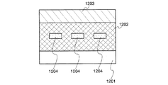
また、本発明の一は、上記キノキサリン誘導体を用いた発光素子である。具体的には、一対の電極間に上述したキノキサリン誘導体を有することを特徴とする発光素子である。 Another embodiment of the present invention is a light-emitting element using the above quinoxaline derivative. Specifically, a light-emitting element having the above-described quinoxaline derivative between a pair of electrodes.
また、本発明の一は、一対の電極間に発光層を有し、発光層は上述したキノキサリン誘導体を有することを特徴とする発光素子である。 Another embodiment of the present invention is a light-emitting element including a light-emitting layer between a pair of electrodes, and the light-emitting layer includes the above-described quinoxaline derivative.
また、本発明の一は、一対の電極間に発光層を有し、発光層は上述したキノキサリン誘導体と蛍光発光性物質を有することを特徴とする発光素子である。 Another embodiment of the present invention is a light-emitting element including a light-emitting layer between a pair of electrodes, and the light-emitting layer includes the above-described quinoxaline derivative and a fluorescent substance.
また、本発明の一は、一対の電極間に発光層を有し、発光層は上述したキノキサリン誘導体と燐光発光性物質を有することを特徴とする発光素子である。 Another embodiment of the present invention is a light-emitting element including a light-emitting layer between a pair of electrodes, and the light-emitting layer includes the above-described quinoxaline derivative and a phosphorescent substance.
また、本発明の発光装置は、一対の電極間にEL層を有し、EL層に、上記のキノキサリン誘導体を含む発光素子と、発光素子の発光を制御する制御手段とを有することを特徴とする。なお、本明細書中における発光装置とは、画像表示デバイス、もしくは光源(照明装置含む)を含む。また、パネルにコネクター、例えばFPC(Flexible printed circuit)もしくはTAB(Tape Automated Bonding)テープもしくはTCP(Tape Carrier Package)が取り付けられたモジュール、TABテープやTCPの先にプリント配線板が設けられたモジュール、または発光素子にCOG(Chip On Glass)方式によりIC(集積回路)が直接実装されたモジュールも全て発光装置に含むものとする。 In addition, a light-emitting device of the present invention includes an EL layer between a pair of electrodes, and the EL layer includes a light-emitting element including the above quinoxaline derivative and a control unit that controls light emission of the light-emitting element. To do. Note that the light-emitting device in this specification includes an image display device or a light source (including a lighting device). In addition, a module in which a connector such as an FPC (Flexible Printed Circuit) or TAB (Tape Automated Bonding) tape or TCP (Tape Carrier Package) is attached to the panel, a TAB tape or a module having a printed wiring board at the end of TCP, Alternatively, a module in which an IC (integrated circuit) is directly mounted on a light emitting element by a COG (Chip On Glass) method is included in the light emitting device.
また、本発明の発光素子を表示部に用いた電子機器も本発明の範疇に含めるものとする。したがって、本発明の電子機器は、表示部を有し、表示部は、上述した発光素子と発光素子の発光を制御する制御手段とを備えたことを特徴とする。 An electronic device using the light-emitting element of the present invention for the display portion is also included in the category of the present invention. Therefore, an electronic device according to the present invention includes a display portion, and the display portion includes the above-described light emitting element and a control unit that controls light emission of the light emitting element.
本発明のキノキサリン誘導体は、バイポーラ性であり、電子輸送性および正孔輸送性の双方に優れている。また、本発明のキノキサリン誘導体は、電気化学的な酸化や還元に対して安定である。 The quinoxaline derivative of the present invention is bipolar and excellent in both electron transport properties and hole transport properties. The quinoxaline derivative of the present invention is stable against electrochemical oxidation and reduction.
さらに、本発明のキノキサリン誘導体はバイポーラ性を有しているため、発光素子に用いることで、駆動電圧が低く、消費電力の小さい発光素子および発光装置を得ることができる。 Further, since the quinoxaline derivative of the present invention has bipolar properties, a light-emitting element and a light-emitting device with low driving voltage and low power consumption can be obtained by using the quinoxaline derivative for a light-emitting element.
また、本発明のキノキサリン誘導体を用いることで、消費電力の小さい電子機器を得ることができる。 In addition, an electronic device with low power consumption can be obtained by using the quinoxaline derivative of the present invention.
以下、本発明の実施の態様について図面を用いて詳細に説明する。但し、本発明は以下の説明に限定されず、本発明の趣旨及びその範囲から逸脱することなくその形態及び詳細を様々に変更し得ることは当業者であれば容易に理解される。従って、本発明は以下に示す実施の形態の記載内容に限定して解釈されるものではない。 Hereinafter, embodiments of the present invention will be described in detail with reference to the drawings. However, the present invention is not limited to the following description, and it is easily understood by those skilled in the art that modes and details can be variously changed without departing from the spirit and scope of the present invention. Therefore, the present invention should not be construed as being limited to the description of the embodiments below.
(実施の形態1)
本発明のキノキサリン誘導体は、下記一般式(1)で表される。
(Embodiment 1)
The quinoxaline derivative of the present invention is represented by the following general formula (1).
(式中、Ar1〜Ar2は、それぞれ同一でも異なっていてもよく、置換もしくは無置換のフェニル基、または置換もしくは無置換のビフェニル基、または置換もしくは無置換のターフェニル基のいずれかを表し、Ar1〜Ar2は、結合していても良い。α1は、炭素数6〜25のアリーレン基を表す。R11〜R15は、それぞれ同一でも異なっていてもよく、水素原子、または炭素数1〜4のアルキル基、または炭素数6〜25の置換もしくは無置換のアリール基のいずれかを表す。) (In the formula, Ar 1 to Ar 2 may be the same or different and each represents a substituted or unsubstituted phenyl group, a substituted or unsubstituted biphenyl group, or a substituted or unsubstituted terphenyl group. Ar 1 to Ar 2 may be bonded to each other, α 1 represents an arylene group having 6 to 25 carbon atoms, R 11 to R 15 may be the same as or different from each other, a hydrogen atom, Or represents an alkyl group having 1 to 4 carbon atoms or a substituted or unsubstituted aryl group having 6 to 25 carbon atoms.)
置換もしくは無置換のフェニル基、または置換もしくは無置換のビフェニル基、または置換もしくは無置換のターフェニル基としては、具体的には、構造式(11−1)〜(11−13)に示す置換基が挙げられる。また、構造式(11−1)〜(11−13)に示す置換基に、さらに炭素数1〜4のアルキル基が置換されていてもよい。炭素数1〜4のアルキル基としては、メチル基、エチル基、イソプロピル基、n−プロピル基、イソブチル基、sec−ブチル基、n−ブチル基、tert−ブチル基などが挙げられる。 Specific examples of the substituted or unsubstituted phenyl group, the substituted or unsubstituted biphenyl group, or the substituted or unsubstituted terphenyl group include substitutions represented by structural formulas (11-1) to (11-13). Groups. Moreover, the C1-C4 alkyl group may be further substituted to the substituent shown to Structural formula (11-1)-(11-13). Examples of the alkyl group having 1 to 4 carbon atoms include methyl group, ethyl group, isopropyl group, n-propyl group, isobutyl group, sec-butyl group, n-butyl group, and tert-butyl group.
また、炭素数6〜25のアリーレン基としては、具体的には、構造式(12−1)〜(12−9)に示す置換基が挙げられる。 Specific examples of the arylene group having 6 to 25 carbon atoms include substituents represented by structural formulas (12-1) to (12-9).
よって、一般式(1)におけるアミン骨格、すなわち一般式(21)で表されるアミン骨格としては、具体的には、構造式(21−1)〜(21−73)に示す構造が挙げられる。 Therefore, specific examples of the amine skeleton in the general formula (1), that is, the amine skeleton represented by the general formula (21) include the structures shown in the structural formulas (21-1) to (21-73). .
また、本発明のキノキサリン誘導体の具体例としては、構造式(101)〜(259)に示されるキノキサリン誘導体を挙げることができる。ただし、本発明はこれらに限定されない。 Specific examples of the quinoxaline derivative of the present invention include quinoxaline derivatives represented by structural formulas (101) to (259). However, the present invention is not limited to these.
本発明のキノキサリン誘導体は、正孔輸送性のアミン骨格と、電子輸送性のキノキサリン骨格とを同一分子内に有するため、バイポーラ性である。また、本発明のキノキサリン誘導体はバイポーラ性なので、発光素子において、発光性物質を分散させる材料として好適に用いることができる。また、本発明のキノキサリン誘導体は、キャリアを輸送することができるため、発光素子において、キャリア輸送層として用いることができる。 The quinoxaline derivative of the present invention is bipolar because it has a hole-transporting amine skeleton and an electron-transporting quinoxaline skeleton in the same molecule. Further, since the quinoxaline derivative of the present invention is bipolar, it can be suitably used as a material for dispersing a light-emitting substance in a light-emitting element. In addition, since the quinoxaline derivative of the present invention can transport carriers, it can be used as a carrier transport layer in a light-emitting element.
また、一般式(1)で表されるキノキサリン誘導体は、Ar1およびAr2が縮合環ではないため、高い一重項励起エネルギーを有する。よって、発光素子において、発光性物質を分散させる材料、または、発光性物質を含む層に接する層に好適に用いることができる。つまり、発光性物質と接するように、本発明のキノキサリン誘導体を用いることができる。特に、上記キノキサリン誘導体は、高い一重項励起エネルギーを有するため、蛍光発光性物質と接するように用いることができる。本発明のキノキサリン誘導体は、高い一重項励起エネルギーを有するため、比較的短波長の蛍光発光性物質に接するように用いた場合でも、蛍光発光性物質からの発光を消光してしまうことを防ぐことができる。 The quinoxaline derivative represented by the general formula (1) has high singlet excitation energy because Ar 1 and Ar 2 are not condensed rings. Therefore, in a light-emitting element, the light-emitting element can be preferably used for a material in which a light-emitting substance is dispersed or a layer in contact with a layer containing the light-emitting substance. That is, the quinoxaline derivative of the present invention can be used so as to be in contact with the light-emitting substance. In particular, since the quinoxaline derivative has high singlet excitation energy, it can be used in contact with a fluorescent substance. Since the quinoxaline derivative of the present invention has high singlet excitation energy, even when used so as to be in contact with a fluorescent substance having a relatively short wavelength, it prevents quenching of the emission from the fluorescent substance. Can do.
また、上記のキノキサリン誘導体において、三重項励起エネルギーの点から、α1およびR11〜R15は、縮合環でないことが好ましい。つまり、上記一般式(1)で表されるキノキサリン誘導体において、α1およびR11〜R15が縮合環でないキノキサリン誘導体であることが好ましい。 In the quinoxaline derivative, α 1 and R 11 to R 15 are preferably not condensed rings from the viewpoint of triplet excitation energy. That is, in the quinoxaline derivative represented by the general formula (1), α 1 and R 11 to R 15 are preferably quinoxaline derivatives that are not condensed rings.
つまり、下記一般式(2)で表されるキノキサリン誘導体であることが好ましい。 That is, a quinoxaline derivative represented by the following general formula (2) is preferable.
(式中、Ar1〜Ar2は、それぞれ同一でも異なっていてもよく、置換もしくは無置換のフェニル基、または置換もしくは無置換のビフェニル基、または置換もしくは無置換のターフェニル基のいずれかを表し、Ar1〜Ar2は、結合していても良い。α2は、炭素数6〜25の縮合環でないアリーレン基を表す。R21〜R25は、それぞれ同一でも異なっていてもよく、水素原子、または炭素数1〜4のアルキル基、または炭素数6〜25の置換もしくは無置換の縮合環でないアリール基のいずれかを表す。) (In the formula, Ar 1 to Ar 2 may be the same or different and each represents a substituted or unsubstituted phenyl group, a substituted or unsubstituted biphenyl group, or a substituted or unsubstituted terphenyl group. Ar 1 to Ar 2 may be bonded to each other, α 2 represents an arylene group that is not a condensed ring having 6 to 25 carbon atoms, and R 21 to R 25 may be the same as or different from each other, It represents either a hydrogen atom, an alkyl group having 1 to 4 carbon atoms, or an aryl group that is not a substituted or unsubstituted condensed ring having 6 to 25 carbon atoms.)
一般式(2)において、α2およびR21〜R25が縮合環でないことにより、高い三重項励起エネルギーを有するキノキサリン誘導体を得ることができる。よって、発光素子において、燐光発光性物質を分散させる材料、または、燐光発光性物質を含む層に接する層に好適に用いることができる。つまり、燐光発光性物質と接するように、本発明のキノキサリン誘導体を用いることができる。本発明のキノキサリン誘導体は、高い三重項励起エネルギーを有するため、比較的短波長の燐光発光性物質に接するように用いた場合でも、燐光発光性物質からの発光を消光してしまうことを防ぐことができる。 In the general formula (2), since α 2 and R 21 to R 25 are not condensed rings, a quinoxaline derivative having high triplet excitation energy can be obtained. Therefore, the light-emitting element can be preferably used for a material in which a phosphorescent substance is dispersed or a layer in contact with a layer containing the phosphorescent substance. That is, the quinoxaline derivative of the present invention can be used so as to be in contact with the phosphorescent substance. Since the quinoxaline derivative of the present invention has a high triplet excitation energy, it prevents the emission of light from the phosphorescent substance from being quenched even when it is used in contact with a phosphorescent substance having a relatively short wavelength. Can do.
縮合環でないアリール基として具体的には、置換もしくは無置換のフェニル基、置換もしくは無置換のビフェニル基、または置換もしくは無置換のフルオレン基などが挙げられる。また、縮合環でないアリーレン基として具体的にはフェニレン基、またはビフェニル−ジイル基、またはフルオレン−ジイル基などが挙げられる。 Specific examples of the aryl group that is not a condensed ring include a substituted or unsubstituted phenyl group, a substituted or unsubstituted biphenyl group, and a substituted or unsubstituted fluorene group. Specific examples of the arylene group that is not a condensed ring include a phenylene group, a biphenyl-diyl group, and a fluorene-diyl group.
つまり、下記一般式(3)で表されるキノキサリン誘導体であることが好ましい。 That is, a quinoxaline derivative represented by the following general formula (3) is preferable.
(式中、Ar1〜Ar2は、それぞれ同一でも異なっていてもよく、置換もしくは無置換のフェニル基、または置換もしくは無置換のビフェニル基、または置換もしくは無置換のターフェニル基のいずれかを表し、Ar1〜Ar2は、結合していても良い。α3は、フェニレン基、またはビフェニル−ジイル基、またはフルオレン−ジイル基のいずれかを表す。R31〜R35は、それぞれ同一でも異なっていてもよく、水素原子、または炭素数1〜4のアルキル基、または置換もしくは無置換のフェニル基、または置換もしくは無置換のビフェニル基、または置換もしくは無置換のフルオレン基のいずれかを表す。) (In the formula, Ar 1 to Ar 2 may be the same or different and each represents a substituted or unsubstituted phenyl group, a substituted or unsubstituted biphenyl group, or a substituted or unsubstituted terphenyl group. Ar 1 to Ar 2 may be bonded to each other, α 3 represents either a phenylene group, a biphenyl-diyl group, or a fluorene-diyl group, and R 31 to R 35 may be the same as each other. Which may be different, each represents a hydrogen atom, an alkyl group having 1 to 4 carbon atoms, a substituted or unsubstituted phenyl group, a substituted or unsubstituted biphenyl group, or a substituted or unsubstituted fluorene group .)
一般式(3)において、合成の点から、α3は、フェニレン基、またはビフェニル−ジイル基であることが好ましい。また、合成の点から、R31〜R35は、水素原子、または炭素数1〜4のアルキル基、または置換もしくは無置換のフェニル基、または置換もしくは無置換のビフェニル基であることが好ましい。これらの置換基は合成ステップ数が少なく、合成が容易である。また、合成に要するコストも少ない。 In general formula (3), from the viewpoint of synthesis, α 3 is preferably a phenylene group or a biphenyl-diyl group. From the viewpoint of synthesis, R 31 to R 35 are preferably a hydrogen atom, an alkyl group having 1 to 4 carbon atoms, a substituted or unsubstituted phenyl group, or a substituted or unsubstituted biphenyl group. These substituents have few synthesis steps and are easy to synthesize. In addition, the cost required for synthesis is low.
よって、下記一般式(4)で表されるキノキサリン誘導体であることが好ましい。 Therefore, a quinoxaline derivative represented by the following general formula (4) is preferable.
(式中、Ar1〜Ar2は、それぞれ同一でも異なっていてもよく、置換もしくは無置換のフェニル基、または置換もしくは無置換のビフェニル基、または置換もしくは無置換のターフェニル基のいずれかを表し、Ar1〜Ar2は、結合していても良い。α4は、フェニレン基、またはビフェニル−ジイル基のいずれかを表す。R41〜R45は、それぞれ同一でも異なっていてもよく、水素原子、または炭素数1〜4のアルキル基、または置換もしくは無置換のフェニル基、または置換もしくは無置換のビフェニル基のいずれかを表す。) (In the formula, Ar 1 to Ar 2 may be the same or different and each represents a substituted or unsubstituted phenyl group, a substituted or unsubstituted biphenyl group, or a substituted or unsubstituted terphenyl group. Ar 1 to Ar 2 may be bonded to each other, α 4 represents either a phenylene group or a biphenyl-diyl group, and R 41 to R 45 may be the same or different, It represents either a hydrogen atom, an alkyl group having 1 to 4 carbon atoms, a substituted or unsubstituted phenyl group, or a substituted or unsubstituted biphenyl group.)
また、本発明の一は、一般式(5)で表されるキノキサリン誘導体である。 Another aspect of the present invention is a quinoxaline derivative represented by the general formula (5).
(式中、AおよびBは、それぞれ同一でも異なっていてもよく、水素またはフェニル基を表し、R1〜R5は、それぞれ同一でも異なっていてもよく、水素原子、または炭素数1〜4のアルキル基、または置換もしくは無置換のフェニル基、または置換もしくは無置換のビフェニル基のいずれかを表す。) (In the formula, A and B may be the same or different and each represents hydrogen or a phenyl group, and R 1 to R 5 may be the same or different, and each represents a hydrogen atom or a carbon number of 1 to 4; Or an alkyl group, a substituted or unsubstituted phenyl group, or a substituted or unsubstituted biphenyl group.)
また、本発明の一は、一般式(6)で表されるキノキサリン誘導体である。 Another aspect of the present invention is a quinoxaline derivative represented by the general formula (6).
(式中、AおよびBは、それぞれ同一でも異なっていてもよく、水素またはフェニル基を表し、R1〜R5は、それぞれ同一でも異なっていてもよく、水素原子、または炭素数1〜4のアルキル基、または置換もしくは無置換のフェニル基、または置換もしくは無置換のビフェニル基のいずれかを表す。) (In the formula, A and B may be the same or different and each represents hydrogen or a phenyl group, and R 1 to R 5 may be the same or different, and each represents a hydrogen atom or a carbon number of 1 to 4; Or an alkyl group, a substituted or unsubstituted phenyl group, or a substituted or unsubstituted biphenyl group.)
また、上記一般式(6)において、合成の点から、R2〜R5は、水素原子であることが好ましい。
In the general formula (6), from the viewpoint of synthesis,
よって、一般式(7)で表されるキノキサリン誘導体であることが好ましい。 Therefore, the quinoxaline derivative represented by the general formula (7) is preferable.
(式中、AおよびBは、それぞれ同一でも異なっていてもよく、水素またはフェニル基を表し、R1は、置換もしくは無置換のフェニル基、または置換もしくは無置換のビフェニル基のいずれかを表す。) (In the formula, A and B may be the same or different and each represents hydrogen or a phenyl group; R 1 represents either a substituted or unsubstituted phenyl group or a substituted or unsubstituted biphenyl group; .)
本発明のキノキサリン誘導体の合成方法としては、種々の反応の適用が可能である。例えば、下記の反応スキーム(A−1)および(A−2)に示す合成反応を行うことによって製造することができる。 As a synthesis method of the quinoxaline derivative of the present invention, various reactions can be applied. For example, it can manufacture by performing the synthesis reaction shown to the following reaction scheme (A-1) and (A-2).
まず、ハロゲン原子X1で置換されたジケトン化合物(化合物B)と1、2−ジアミノベンゼンを骨格に含む化合物(化合物A)との縮合反応によってキノキサリン骨格を形成する。ハロゲン原子X1としては臭素、ヨウ素、塩素が挙げられるが、取扱の容易さ、適度な反応性を考慮すると臭素またはヨウ素が好ましい。 First, a quinoxaline skeleton by condensation reaction of a diketone compound substituted with a halogen atom X 1 (Compound B) with 1,2-diaminobenzene compounds containing the skeleton (Compound A). Examples of the halogen atom X 1 include bromine, iodine, and chlorine, but bromine or iodine is preferable in consideration of ease of handling and appropriate reactivity.
得られるハロゲン化アリールで置換されたキノキサリン化合物(化合物C)に対し、塩基存在下、1当量のジアリールアミン(Ar1−NH−Ar2)(化合物D)をパラジウム触媒、あるいは一価の銅等の金属化合物、あるいは銅等の金属を用いてカップリングすることで、目的とする本発明のキノキサリン誘導体を合成することができる。塩基は炭酸カリウム、炭酸ナトリウムなどの無機塩基や、金属アルコキシドなどの有機塩基などを用いることができる。パラジウム触媒としては酢酸パラジウム(II)、ビス(ジベンジリデンアセトン)パラジウム(0)などを用いることができる。また、溶媒としては、トルエン、キシレン、ベンゼンなどを用いることができる。 In the presence of a base, 1 equivalent of diarylamine (Ar 1 —NH—Ar 2 ) (compound D) is converted into a palladium catalyst, monovalent copper, or the like with respect to the obtained quinoxaline compound (compound C) substituted with an aryl halide. The target quinoxaline derivative of the present invention can be synthesized by coupling using a metal compound such as copper or a metal such as copper. As the base, an inorganic base such as potassium carbonate or sodium carbonate, an organic base such as metal alkoxide, or the like can be used. As the palladium catalyst, palladium (II) acetate, bis (dibenzylideneacetone) palladium (0), or the like can be used. As the solvent, toluene, xylene, benzene, or the like can be used.
なお、上記スキーム中のジアリールアミン(Ar1−NH−Ar2)(化合物D)は、例えば以下のようなスキームで合成することができる。 Incidentally, diaryl amine in the above scheme (Ar 1 -NH-Ar 2) ( Compound D) can be synthesized by the schemes, for example, the following.
アリールアミン化合物(Ar2−NH2)とハロゲン化アリール(Ar1−X2)をパラジウム触媒、あるいは一価の銅等の金属化合物、あるいは銅等の金属を用いてカップリングすることで、ジアリールアミン(Ar1−NH−Ar2)(化合物D)を合成することができる(合成スキーム(A−3))。この反応において、溶媒としては、トルエン、キシレン、ベンゼンなどを用いることができる。 A diaryl is obtained by coupling an arylamine compound (Ar 2 —NH 2 ) and a halogenated aryl (Ar 1 —X 2 ) using a palladium catalyst, a metal compound such as monovalent copper, or a metal such as copper. An amine (Ar 1 —NH—Ar 2 ) (Compound D) can be synthesized (Synthesis scheme (A-3)). In this reaction, toluene, xylene, benzene, or the like can be used as the solvent.
次に、Ar1がビフェニル基の場合、2位または3位または4位がハロゲン(X3)で置換されたハロゲン置換ビフェニルに対し、塩基存在下、1当量のアリールアミン(Ar2−NH2)をパラジウム触媒、あるいは一価の銅等の金属化合物、あるいは銅等の金属を用いてカップリングすることで、目的とするアリールアミン(Ar1−NH−Ar2;Ar1はビフェニル基)を得ることができる(合成スキーム(A−4))。塩基は炭酸カリウム、炭酸ナトリウムなどの無機塩基や、金属アルコキシドなどの有機塩基などを用いることができる。パラジウム触媒としては酢酸パラジウム(II)、ビス(ジベンジリデンアセトン)パラジウム(0)などを用いることができる。また、溶媒としては、トルエン、キシレン、ベンゼンなどを用いることができる。 Next, when Ar 1 is a biphenyl group, 1 equivalent of an arylamine (Ar 2 —NH 2 ) is present in the presence of a base with respect to the halogen-substituted biphenyl substituted at the 2-position, 3-position or 4-position with halogen (X 3 ). ) With a palladium catalyst, a metal compound such as monovalent copper, or a metal such as copper, to thereby produce the target arylamine (Ar 1 —NH—Ar 2 ; Ar 1 is a biphenyl group). (Synthesis scheme (A-4)). As the base, an inorganic base such as potassium carbonate or sodium carbonate, an organic base such as metal alkoxide, or the like can be used. As the palladium catalyst, palladium (II) acetate, bis (dibenzylideneacetone) palladium (0), or the like can be used. As the solvent, toluene, xylene, benzene, or the like can be used.
また、Ar1がビフェニル基で、かつAr2もビフェニル基の場合、二つのフェニル基がいずれもハロゲン(X5およびX4)で置換されたジフェニルアミンに対し、塩基存在下、2当量のフェニルボロン酸またはフェニルホウ素化合物(例えば、2−フェニル−4,4,5,5−テトラメチル−1,3,2−ジオキサボロランなど)をパラジウム触媒を用いてカップリングすることで、目的とするアリールアミン(Ar1−NH−Ar2;Ar1、Ar2共にビフェニル基)を得ることもできる(合成スキーム(A−5))。塩基は炭酸カリウム、炭酸ナトリウムなどの無機塩基や、金属アルコキシドなどの有機塩基などを用いることができる。パラジウム触媒としては酢酸パラジウム(II)、テトラキス(トリフェニルホスフィン)パラジウム(0)などを用いることができる。また、溶媒としては、エタノールなどのアルコール、アルコールとトルエンあるいは、アルコールとキシレン、アルコールとベンゼンなどの混合溶媒、エチレングリコールジエチルエーテル、エチレングリコールジメチルエーテルなどのエーテル溶媒を用いることができる。この方法の場合、人体に有害な物質である4−アミノビフェニルを用いることなく、N,N−ジ(4−ビフェニリル)アミンを合成することができるというメリットがある。 In addition, when Ar 1 is a biphenyl group and Ar 2 is also a biphenyl group, 2 equivalents of phenylboron in the presence of a base with respect to diphenylamine in which both two phenyl groups are substituted with halogens (X 5 and X 4 ) By coupling an acid or a phenylboron compound (for example, 2-phenyl-4,4,5,5-tetramethyl-1,3,2-dioxaborolane etc.) using a palladium catalyst, the desired arylamine ( Ar 1 —NH—Ar 2 ; both Ar 1 and Ar 2 may be a biphenyl group) (synthesis scheme (A-5)). As the base, an inorganic base such as potassium carbonate or sodium carbonate, an organic base such as metal alkoxide, or the like can be used. As the palladium catalyst, palladium (II) acetate, tetrakis (triphenylphosphine) palladium (0), or the like can be used. As the solvent, an alcohol such as ethanol, an alcohol and toluene, a mixed solvent such as alcohol and xylene, an alcohol and benzene, or an ether solvent such as ethylene glycol diethyl ether or ethylene glycol dimethyl ether can be used. In the case of this method, there is an advantage that N, N-di (4-biphenylyl) amine can be synthesized without using 4-aminobiphenyl, which is a harmful substance to the human body.
また、Ar1がターフェニル基であるアリールアミン(Ar1−NH−Ar2)を合成する場合、まず、2位または3位または4位がハロゲン(X5)で置換されたアニリンに対し、塩基存在下、2位または3位または4位がフェニル基で置換された1当量のフェニルボロン酸またはフェニルホウ素化合物をパラジウム触媒を用いてカップリングすることで、置換位置の異なる種々のターフェニルアミンを合成できる(合成スキーム(A−6))。塩基は炭酸カリウム、炭酸ナトリウムなどの無機塩基や、金属アルコキシドなどの有機塩基などを用いることができる。また、パラジウム触媒としては酢酸パラジウム(II)、テトラキス(トリフェニルホスフィン)パラジウム(0)などを用いることができる。また、溶媒としては、エタノールなどのアルコール、アルコールとトルエンあるいは、アルコールとキシレン、アルコールとベンゼンなどの混合溶媒、エチレングリコールジエチルエーテル、エチレングリコールジメチルエーテルなどのエーテル溶媒を用いることができる。 Further, when synthesizing an arylamine (Ar 1 —NH—Ar 2 ) in which Ar 1 is a terphenyl group, first, with respect to aniline substituted at the 2-position, 3-position or 4-position with halogen (X 5 ), In the presence of a base, by coupling 1 equivalent of a phenylboronic acid or phenylboron compound substituted at the 2-position, 3-position or 4-position with a phenyl group using a palladium catalyst, various terphenylamines having different substitution positions can be obtained. Can be synthesized (Synthesis Scheme (A-6)). As the base, an inorganic base such as potassium carbonate or sodium carbonate, an organic base such as metal alkoxide, or the like can be used. Moreover, palladium acetate (II), tetrakis (triphenylphosphine) palladium (0), etc. can be used as a palladium catalyst. As the solvent, an alcohol such as ethanol, an alcohol and toluene, a mixed solvent such as alcohol and xylene, an alcohol and benzene, or an ether solvent such as ethylene glycol diethyl ether or ethylene glycol dimethyl ether can be used.
そして、ハロゲンで置換されたアリール(Ar2−X6)に対し、塩基存在下、上記で得られたターフェニルアミン1当量をパラジウム触媒、あるいは一価の銅等の金属化合物、あるいは銅等の金属を用いてカップリングすることで、目的とするアリールアミン(Ar1−NH−Ar2;Ar1はターフェニル基)を得ることができる(合成スキーム(A−7))。塩基は炭酸カリウム、炭酸ナトリウムなどの無機塩基や、金属アルコキシドなどの有機塩基などを用いることができる。パラジウム触媒としては酢酸パラジウム(II)、ビス(ジベンジリデンアセトン)パラジウム(0)などを用いることができる。また、溶媒としては、トルエン、キシレン、ベンゼンなどを用いることができる。 Then, with respect to aryl substituted with halogen (Ar 2 -X 6 ), in the presence of a base, 1 equivalent of the terphenylamine obtained above is converted into a palladium catalyst, a metal compound such as monovalent copper, or copper. By coupling with a metal, a target arylamine (Ar 1 —NH—Ar 2 ; Ar 1 is a terphenyl group) can be obtained (Synthesis scheme (A-7)). As the base, an inorganic base such as potassium carbonate or sodium carbonate, an organic base such as metal alkoxide, or the like can be used. As the palladium catalyst, palladium (II) acetate, bis (dibenzylideneacetone) palladium (0), or the like can be used. As the solvent, toluene, xylene, benzene, or the like can be used.
また、Ar1がターフェニル基の場合で、かつターフェニル基の中心のベンゼン環がアミノ基で置換されている場合は、まず2箇所がハロゲン(X7)で置換されたアニリンに対し、塩基存在下、2当量のフェニルボロン酸またはフェニルホウ素化合物をパラジウム触媒を用いてカップリングすることで、ターフェニル基の中心のベンゼン環がアミノ基で置換されたターフェニルアミンを合成する(合成スキーム(A−8))。塩基は炭酸カリウム、炭酸ナトリウムなどの無機塩基や、金属アルコキシドなどの有機塩基などを用いることができる。また、パラジウム触媒としては酢酸パラジウム(II)、テトラキス(トリフェニルホスフィン)パラジウム(0)などを用いることができる。また、溶媒としては、エタノールなどのアルコール、アルコールとトルエンあるいは、アルコールとキシレン、アルコールとベンゼンなどの混合溶媒、エチレングリコールジエチルエーテル、エチレングリコールジメチルエーテルなどのエーテル溶媒を用いることができる。 In the case where Ar 1 is a terphenyl group and the benzene ring at the center of the terphenyl group is substituted with an amino group, first, a base with respect to aniline substituted with halogen (X 7 ) at two positions In the presence, 2 equivalents of phenylboronic acid or phenylboron compound are coupled using a palladium catalyst to synthesize terphenylamine in which the benzene ring at the center of the terphenyl group is substituted with an amino group (synthesis scheme ( A-8)). As the base, an inorganic base such as potassium carbonate or sodium carbonate, an organic base such as metal alkoxide, or the like can be used. Moreover, palladium acetate (II), tetrakis (triphenylphosphine) palladium (0), etc. can be used as a palladium catalyst. As the solvent, an alcohol such as ethanol, an alcohol and toluene, a mixed solvent such as alcohol and xylene, an alcohol and benzene, or an ether solvent such as ethylene glycol diethyl ether or ethylene glycol dimethyl ether can be used.
そして、ハロゲン置換されたアリール(Ar2−X8)に対し、塩基存在下、得られたターフェニルアミン1当量をパラジウム触媒、あるいは一価の銅等の金属化合物、あるいは銅等の金属を用いてカップリングすることで、目的とするアリールアミン(Ar1−NH−Ar2;Ar1はターフェニル基)を得ることができる(合成スキーム(A−9))。塩基は炭酸カリウム、炭酸ナトリウムなどの無機塩基や、金属アルコキシドなどの有機塩基などを用いることができる。パラジウム触媒としては酢酸パラジウム(II)、ビス(ジベンジリデンアセトン)パラジウム(0)などを用いることができる。また、溶媒としては、トルエン、キシレン、ベンゼンなどを用いることができる。 Then, with respect to the halogen-substituted aryl (Ar 2 -X 8 ), in the presence of a base, 1 equivalent of the obtained terphenylamine is used with a palladium catalyst, a metal compound such as monovalent copper, or a metal such as copper. To obtain the target arylamine (Ar 1 —NH—Ar 2 ; Ar 1 is a terphenyl group) (Synthesis scheme (A-9)). As the base, an inorganic base such as potassium carbonate or sodium carbonate, an organic base such as metal alkoxide, or the like can be used. As the palladium catalyst, palladium (II) acetate, bis (dibenzylideneacetone) palladium (0), or the like can be used. As the solvent, toluene, xylene, benzene, or the like can be used.
本発明のキノキサリン誘導体は、バイポーラ性であり、電子輸送性および正孔輸送性の双方に優れている。よって、本発明のキノキサリン誘導体をエレクトロニクスデバイスに用いることにより、良好な電気特性を得ることができる。また、本発明のキノキサリン誘導体は電気化学的な酸化や還元に対して安定であるため、本発明のキノキサリン誘導体をエレクトロニクスデバイスに用いることにより、長寿命なエレクトロニクスデバイスを得ることができる。 The quinoxaline derivative of the present invention is bipolar and excellent in both electron transport properties and hole transport properties. Therefore, good electrical characteristics can be obtained by using the quinoxaline derivative of the present invention for an electronic device. In addition, since the quinoxaline derivative of the present invention is stable against electrochemical oxidation and reduction, an electronic device having a long life can be obtained by using the quinoxaline derivative of the present invention for an electronic device.
(実施の形態2)
本発明のキノキサリン誘導体を用いた発光素子の一態様について図1(A)を用いて以下に説明する。
(Embodiment 2)
One mode of a light-emitting element using the quinoxaline derivative of the present invention is described below with reference to FIG.
本発明の発光素子は、一対の電極間に複数の層を有する。本形態において、発光素子は、第1の電極102と、第2の電極104と、第1の電極102と第2の電極との間に設けられたEL層とから構成されている。なお、本形態では第1の電極102は陽極として機能し、第2の電極104は陰極として機能するものとして、以下説明をする。つまり、第1の電極102の方が第2の電極104よりも電位が高くなるように、第1の電極102と第2の電極104に電圧を印加したときに、発光が得られるものとして、以下説明をする。
The light-emitting element of the present invention has a plurality of layers between a pair of electrodes. In this embodiment mode, the light-emitting element includes a
基板101は発光素子の支持体として用いられる。基板101としては、例えばガラス、またはプラスチックなどを用いることができる。なお、発光素子の支持体として機能するものであれば、これら以外のものでもよい。
The
第1の電極102としては、仕事関数の大きい(具体的には4.0eV以上)金属、合金、導電性化合物、およびこれらの混合物などを用いることが好ましい。具体的には、例えば、酸化インジウム−酸化スズ(ITO:Indium Tin Oxide)、珪素若しくは酸化珪素を含有した酸化インジウム−酸化スズ、酸化インジウム−酸化亜鉛(IZO:Indium Zinc Oxide)、酸化タングステン及び酸化亜鉛を含有した酸化インジウム(IWZO)等が挙げられる。これらの導電性金属酸化物膜は、通常スパッタにより成膜されるが、ゾル−ゲル法などを応用して作製しても構わない。例えば、酸化インジウム−酸化亜鉛(IZO)は、酸化インジウムに対し1〜20wt%の酸化亜鉛を加えたターゲットを用いてスパッタリング法により形成することができる。また、酸化タングステン及び酸化亜鉛を含有した酸化インジウム(IWZO)は、酸化インジウムに対し酸化タングステンを0.5〜5wt%、酸化亜鉛を0.1〜1wt%含有したターゲットを用いてスパッタリング法により形成することができる。この他、金(Au)、白金(Pt)、ニッケル(Ni)、タングステン(W)、クロム(Cr)、モリブデン(Mo)、鉄(Fe)、コバルト(Co)、銅(Cu)、パラジウム(Pd)、または金属材料の窒化物(例えば、窒化チタン)等が挙げられる。
As the
EL層103は、層の積層構造については特に限定されず、電子輸送性の高い物質または正孔輸送性の高い物質、電子注入性の高い物質、正孔注入性の高い物質、バイポーラ性(電子及び正孔の輸送性の高い物質)の物質等から成る層と、実施の形態1で示した本発明のキノキサリン誘導体を含む層とを適宜組み合わせて構成すればよい。例えば、正孔注入層、正孔輸送層、発光層、電子輸送層、電子注入層等を適宜組み合わせて構成することができる。本実施の形態では、EL層103は、第1の電極102の上に順に積層した正孔注入層111、正孔輸送層112、発光層113、電子輸送層114を有する構成について説明する。各層を構成する材料について以下に具体的に示す。
The layer structure of the
正孔注入層111は、正孔注入性の高い物質を含む層である。モリブデン酸化物やバナジウム酸化物、ルテニウム酸化物、タングステン酸化物、マンガン酸化物等を用いることができる。この他、フタロシアニン(略称:H2Pc)や銅フタロシアニン(略称:CuPc)等のフタロシアニン系の化合物、4,4’−ビス[N−(4−ジフェニルアミノフェニル)−N−フェニルアミノ]ビフェニル(略称:DPAB)、4,4’−ビス(N−{4−[N−(3−メチルフェニル)−N−フェニルアミノ]フェニル}−N−フェニルアミノ)ビフェニル(略称:DNTPD)等の芳香族アミン化合物、或いはポリ(3,4−エチレンジオキシチオフェン)/ポリ(スチレンスルホン酸)(PEDOT/PSS)等の高分子等によっても正孔注入層111を形成することができる。
The
また、正孔注入層111として、正孔輸送性の高い物質にアクセプター性物質を含有させた複合材料を用いることができる。なお、正孔輸送性の高い物質にアクセプター性物質を含有させたものを用いることにより、電極の仕事関数に依らず電極を形成する材料を選ぶことができる。つまり、第1の電極102として仕事関数の大きい材料だけでなく、仕事関数の小さい材料を用いることができる。アクセプター性物質としては、7,7,8,8−テトラシアノ−2,3,5,6−テトラフルオロキノジメタン(略称:F4−TCNQ)、クロラニル等を挙げることができる。また、遷移金属酸化物を挙げることができる。また元素周期表における第4族乃至第8族に属する金属の酸化物を挙げることができる。具体的には、酸化バナジウム、酸化ニオブ、酸化タンタル、酸化クロム、酸化モリブデン、酸化タングステン、酸化マンガン、酸化レニウムは電子受容性が高いため好ましい。中でも特に、酸化モリブデンは大気中でも安定であり、吸湿性が低く、扱いやすいため好ましい。
For the hole-injecting
複合材料に用いる正孔輸送性の高い物質としては、芳香族アミン化合物、カルバゾール誘導体、芳香族炭化水素、高分子化合物(オリゴマー、デンドリマー、ポリマー等)など、種々の化合物を用いることができる。なお、複合材料に用いる有機化合物としては、正孔輸送性の高い有機化合物であることが好ましい。具体的には、10−6cm2/Vs以上の正孔移動度を有する物質であることが好ましい。但し、電子よりも正孔の輸送性の高い物質であれば、これら以外のものを用いてもよい。以下では、複合材料に用いることのできる有機化合物を具体的に列挙する。 As the substance having a high hole-transport property used for the composite material, various compounds such as an aromatic amine compound, a carbazole derivative, an aromatic hydrocarbon, and a high molecular compound (oligomer, dendrimer, polymer, and the like) can be used. Note that the organic compound used for the composite material is preferably an organic compound having a high hole-transport property. Specifically, a substance having a hole mobility of 10 −6 cm 2 / Vs or higher is preferable. Note that other than these substances, any substance that has a property of transporting more holes than electrons may be used. Below, the organic compound which can be used for a composite material is listed concretely.
例えば、芳香族アミン化合物としては、N,N’−ジ(p−トリル)−N,N’−ジフェニル−p−フェニレンジアミン(略称:DTDPPA)、4,4’−ビス[N−(4−ジフェニルアミノフェニル)−N−フェニルアミノ]ビフェニル(略称:DPAB)、4,4’−ビス(N−{4−[N−(3−メチルフェニル)−N−フェニルアミノ]フェニル}−N−フェニルアミノ)ビフェニル(略称:DNTPD)、1,3,5−トリス[N−(4−ジフェニルアミノフェニル)−N−フェニルアミノ]ベンゼン(略称:DPA3B)等を挙げることができる。 For example, as an aromatic amine compound, N, N′-di (p-tolyl) -N, N′-diphenyl-p-phenylenediamine (abbreviation: DTDPPA), 4,4′-bis [N- (4- Diphenylaminophenyl) -N-phenylamino] biphenyl (abbreviation: DPAB), 4,4′-bis (N- {4- [N- (3-methylphenyl) -N-phenylamino] phenyl} -N-phenyl Amino) biphenyl (abbreviation: DNTPD), 1,3,5-tris [N- (4-diphenylaminophenyl) -N-phenylamino] benzene (abbreviation: DPA3B), and the like can be given.
複合材料に用いることのできるカルバゾール誘導体としては、具体的には、3−[N−(9−フェニルカルバゾール−3−イル)−N−フェニルアミノ]−9−フェニルカルバゾール(略称:PCzPCA1)、3,6−ビス[N−(9−フェニルカルバゾール−3−イル)−N−フェニルアミノ]−9−フェニルカルバゾール(略称:PCzPCA2)、3−[N−(1−ナフチル)−N−(9−フェニルカルバゾール−3−イル)アミノ]−9−フェニルカルバゾール(略称:PCzPCN1)等を挙げることができる。 Specific examples of the carbazole derivative that can be used for the composite material include 3- [N- (9-phenylcarbazol-3-yl) -N-phenylamino] -9-phenylcarbazole (abbreviation: PCzPCA1), 3 , 6-Bis [N- (9-phenylcarbazol-3-yl) -N-phenylamino] -9-phenylcarbazole (abbreviation: PCzPCA2), 3- [N- (1-naphthyl) -N- (9- Phenylcarbazol-3-yl) amino] -9-phenylcarbazole (abbreviation: PCzPCN1) and the like.
また、複合材料に用いることのできるカルバゾール誘導体としては、他に、4,4’−ジ(N−カルバゾリル)ビフェニル(略称:CBP)、1,3,5−トリス[4−(N−カルバゾリル)フェニル]ベンゼン(略称:TCPB)、9−[4−(N−カルバゾリル)]フェニル−10−フェニルアントラセン(略称:CzPA)、1,4−ビス[4−(N−カルバゾリル)フェニル]−2,3,5,6−テトラフェニルベンゼン等を用いることができる。 As other carbazole derivatives that can be used for the composite material, 4,4′-di (N-carbazolyl) biphenyl (abbreviation: CBP), 1,3,5-tris [4- (N-carbazolyl) Phenyl] benzene (abbreviation: TCPB), 9- [4- (N-carbazolyl)] phenyl-10-phenylanthracene (abbreviation: CzPA), 1,4-bis [4- (N-carbazolyl) phenyl] -2, 3,5,6-tetraphenylbenzene or the like can be used.
また、複合材料に用いることのできる芳香族炭化水素としては、例えば、2−tert−ブチル−9,10−ジ(2−ナフチル)アントラセン(略称:t−BuDNA)、2−tert−ブチル−9,10−ジ(1−ナフチル)アントラセン、9,10−ビス(3,5−ジフェニルフェニル)アントラセン(略称:DPPA)、2−tert−ブチル−9,10−ビス(4−フェニルフェニル)アントラセン(略称:t−BuDBA)、9,10−ジ(2−ナフチル)アントラセン(略称:DNA)、9,10−ジフェニルアントラセン(略称:DPAnth)、2−tert−ブチルアントラセン(略称:t−BuAnth)、9,10−ビス(4−メチル−1−ナフチル)アントラセン(略称:DMNA)、2−tert−ブチル−9,10−ビス[2−(1−ナフチル)フェニル]アントラセン、9,10−ビス[2−(1−ナフチル)フェニル]アントラセン、2,3,6,7−テトラメチル−9,10−ジ(1−ナフチル)アントラセン、2,3,6,7−テトラメチル−9,10−ジ(2−ナフチル)アントラセン、9,9’−ビアントリル、10,10’−ジフェニル−9,9’−ビアントリル、10,10’−ビス(2−フェニルフェニル)−9,9’−ビアントリル、10,10’−ビス[(2,3,4,5,6−ペンタフェニル)フェニル]−9,9’−ビアントリル、アントラセン、テトラセン、ルブレン、ペリレン、2,5,8,11−テトラ(tert−ブチル)ペリレン等が挙げられる。また、この他、ペンタセン、コロネン等も用いることができる。このように、1×10−6cm2/Vs以上の正孔移動度を有し、炭素数14〜42である芳香族炭化水素を用いることがより好ましい。 Examples of aromatic hydrocarbons that can be used for the composite material include 2-tert-butyl-9,10-di (2-naphthyl) anthracene (abbreviation: t-BuDNA), 2-tert-butyl-9. , 10-di (1-naphthyl) anthracene, 9,10-bis (3,5-diphenylphenyl) anthracene (abbreviation: DPPA), 2-tert-butyl-9,10-bis (4-phenylphenyl) anthracene ( Abbreviations: t-BuDBA), 9,10-di (2-naphthyl) anthracene (abbreviation: DNA), 9,10-diphenylanthracene (abbreviation: DPAnth), 2-tert-butylanthracene (abbreviation: t-BuAnth), 9,10-bis (4-methyl-1-naphthyl) anthracene (abbreviation: DMNA), 2-tert-butyl-9, 0-bis [2- (1-naphthyl) phenyl] anthracene, 9,10-bis [2- (1-naphthyl) phenyl] anthracene, 2,3,6,7-tetramethyl-9,10-di (1 -Naphthyl) anthracene, 2,3,6,7-tetramethyl-9,10-di (2-naphthyl) anthracene, 9,9'-bianthryl, 10,10'-diphenyl-9,9'-bianthryl, 10 , 10′-bis (2-phenylphenyl) -9,9′-bianthryl, 10,10′-bis [(2,3,4,5,6-pentaphenyl) phenyl] -9,9′-bianthryl, Anthracene, tetracene, rubrene, perylene, 2,5,8,11-tetra (tert-butyl) perylene and the like can be mentioned. In addition, pentacene, coronene, and the like can also be used. Thus, it is more preferable to use an aromatic hydrocarbon having a hole mobility of 1 × 10 −6 cm 2 / Vs or more and having 14 to 42 carbon atoms.
なお、複合材料に用いることのできる芳香族炭化水素は、ビニル骨格を有していてもよい。ビニル基を有している芳香族炭化水素としては、例えば、4,4’−ビス(2,2−ジフェニルビニル)ビフェニル(略称:DPVBi)、9,10−ビス[4−(2,2−ジフェニルビニル)フェニル]アントラセン(略称:DPVPA)等が挙げられる。 Note that the aromatic hydrocarbon that can be used for the composite material may have a vinyl skeleton. As the aromatic hydrocarbon having a vinyl group, for example, 4,4′-bis (2,2-diphenylvinyl) biphenyl (abbreviation: DPVBi), 9,10-bis [4- (2,2- Diphenylvinyl) phenyl] anthracene (abbreviation: DPVPA) and the like.
また、ポリ(N−ビニルカルバゾール)(略称:PVK)やポリ(4−ビニルトリフェニルアミン)(略称:PVTPA)、ポリ[N−(4−{N’−[4−(4−ジフェニルアミノ)フェニル]フェニル−N’−フェニルアミノ}フェニル)メタクリルアミド](略称:PTPDMA)ポリ[N,N’−ビス(4−ブチルフェニル)−N,N’−ビス(フェニル)ベンジジン](略称:Poly−TPD)等の高分子化合物を用いることもできる。 In addition, poly (N-vinylcarbazole) (abbreviation: PVK), poly (4-vinyltriphenylamine) (abbreviation: PVTPA), poly [N- (4- {N ′-[4- (4-diphenylamino)] Phenyl] phenyl-N′-phenylamino} phenyl) methacrylamide] (abbreviation: PTPDMA) poly [N, N′-bis (4-butylphenyl) -N, N′-bis (phenyl) benzidine] (abbreviation: Poly High molecular compounds such as -TPD) can also be used.
正孔輸送層112は、正孔輸送性の高い物質を含む層である。正孔輸送性の高い物質としては、例えば、4,4’−ビス[N−(1−ナフチル)−N−フェニルアミノ]ビフェニル(略称:NPB)やN,N’−ビス(3−メチルフェニル)−N,N’−ジフェニル−[1,1’−ビフェニル]−4,4’−ジアミン(略称:TPD)、4,4’,4’’−トリス(N,N−ジフェニルアミノ)トリフェニルアミン(略称:TDATA)、4,4’,4’’−トリス[N−(3−メチルフェニル)−N−フェニルアミノ]トリフェニルアミン(略称:MTDATA)、4,4’−ビス[N−(スピロ−9,9’−ビフルオレン−2−イル)−N―フェニルアミノ]−1,1’−ビフェニル(略称:BSPB)などの芳香族アミン化合物等を用いることができる。ここに述べた物質は、主に10−6cm2/Vs以上の正孔移動度を有する物質である。但し、電子よりも正孔の輸送性の高い物質であれば、これら以外のものを用いてもよい。なお、正孔輸送性の高い物質を含む層は、単層のものだけでなく、上記物質からなる層が二層以上積層したものとしてもよい。
The
また、正孔輸送層112として、ポリ(N−ビニルカルバゾール)(略称:PVK)やポリ(4−ビニルトリフェニルアミン)(略称:PVTPA)等の高分子化合物を用いることもできる。
For the hole-
発光層113は、発光性の物質を含む層である。本実施の形態では、発光層113は実施の形態1で示した本発明のキノキサリン誘導体を含む。本発明のキノキサリン誘導体は、青〜緑色の発光を示すため、発光性物質として発光素子に好適に用いることができる。
The
電子輸送層114は、電子輸送性の高い物質を含む層である。例えば、トリス(8−キノリノラト)アルミニウム(略称:Alq)、トリス(4−メチル−8−キノリノラト)アルミニウム(略称:Almq3)、ビス(10−ヒドロキシベンゾ[h]キノリナト)ベリリウム(略称:BeBq2)、ビス(2−メチル−8−キノリノラト)(4−フェニルフェノラト)アルミニウム(略称:BAlq)など、キノリン骨格またはベンゾキノリン骨格を有する金属錯体等からなる層である。また、この他ビス[2−(2−ヒドロキシフェニル)ベンズオキサゾラト]亜鉛(略称:Zn(BOX)2)、ビス[2−(2−ヒドロキシフェニル)ベンゾチアゾラト]亜鉛(略称:Zn(BTZ)2)などのオキサゾール系、チアゾール系配位子を有する金属錯体なども用いることができる。さらに、金属錯体以外にも、2−(4−ビフェニリル)−5−(4−tert−ブチルフェニル)−1,3,4−オキサジアゾール(略称:PBD)や、1,3−ビス[5−(p−tert−ブチルフェニル)−1,3,4−オキサジアゾール−2−イル]ベンゼン(略称:OXD−7)、3−(4−ビフェニリル)−4−フェニル−5−(4−tert−ブチルフェニル)−1,2,4−トリアゾール(略称:TAZ)、バソフェナントロリン(略称:BPhen)、バソキュプロイン(略称:BCP)なども用いることができる。ここに述べた物質は、主に10−6cm2/Vs以上の電子移動度を有する物質である。なお、正孔よりも電子の輸送性の高い物質であれば、上記以外の物質を電子輸送層として用いても構わない。また、電子輸送層は、単層のものだけでなく、上記物質からなる層が二層以上積層したものとしてもよい。
The
また、電子注入層を設けてもよい。電子注入層としては、フッ化リチウム(LiF)、フッ化セシウム(CsF)、フッ化カルシウム(CaF2)等のようなアルカリ金属又はアルカリ土類金属又はそれらの化合物を用いることができる。例えば、電子輸送性を有する物質からなる層中にアルカリ金属又はアルカリ土類金属又はそれらの化合物を含有させたもの、例えばAlq中にマグネシウム(Mg)を含有させたもの等を用いることができる。なお、電子注入層として、電子輸送性を有する物質からなる層中にアルカリ金属又はアルカリ土類金属を含有させたものを用いることにより、第2の電極104からの電子注入が効率良く行われるためより好ましい。
Further, an electron injection layer may be provided. As the electron injection layer, an alkali metal or an alkaline earth metal such as lithium fluoride (LiF), cesium fluoride (CsF), calcium fluoride (CaF 2 ), or the like can be used. For example, a layer made of a substance having an electron transporting property containing an alkali metal or an alkaline earth metal or a compound thereof, for example, a layer containing magnesium (Mg) in Alq can be used. Note that by using an electron injection layer containing an alkali metal or an alkaline earth metal in a layer made of a substance having an electron transporting property, electron injection from the
第2の電極104を形成する物質としては、仕事関数の小さい(具体的には3.8eV以下)金属、合金、電気伝導性化合物、およびこれらの混合物などを用いることができる。このような陰極材料の具体例としては、元素周期表の第1族または第2族に属する元素、すなわちリチウム(Li)やセシウム(Cs)等のアルカリ金属、およびマグネシウム(Mg)、カルシウム(Ca)、ストロンチウム(Sr)等のアルカリ土類金属、およびこれらを含む合金(MgAg、AlLi)、ユウロピウム(Eu)、イッテルビウム(Yb)等の希土類金属およびこれらを含む合金等が挙げられる。しかしながら、第2の電極104と電子輸送層との間に、電子注入層を設けることにより、仕事関数の大小に関わらず、Al、Ag、ITO、珪素若しくは酸化珪素を含有した酸化インジウム−酸化スズ等様々な導電性材料を第2の電極104として用いることができる。これら導電性材料は、スパッタリング法やインクジェット法、スピンコート法等を用いて成膜することが可能である。
As a material for forming the
また、EL層103の形成方法としては、乾式法、湿式法を問わず、種々の方法を用いることができる。例えば、真空蒸着法、インクジェット法またはスピンコート法など用いても構わない。また各電極または各層ごとに異なる成膜方法を用いて形成しても構わない。
In addition, as a formation method of the
電極についても、ゾル−ゲル法を用いて湿式法で形成しても良いし、金属材料のペーストを用いて湿式法で形成してもよい。また、スパッタリング法や真空蒸着法などの乾式法を用いて形成しても良い。 The electrode may also be formed by a wet method using a sol-gel method, or may be formed by a wet method using a paste of a metal material. Alternatively, a dry method such as a sputtering method or a vacuum evaporation method may be used.
以上のような構成を有する本発明の発光素子は、第1の電極102と第2の電極104との間に生じた電位差により電流が流れ、発光性の高い物質を含む層である発光層113において正孔と電子とが再結合し、発光するものである。つまり発光層113に発光領域が形成されるような構成となっている。
In the light-emitting element of the present invention having the above structure, a current flows due to a potential difference generated between the
発光は、第1の電極102または第2の電極104のいずれか一方または両方を通って外部に取り出される。従って、第1の電極102または第2の電極104のいずれか一方または両方は、透光性を有する電極で成る。第1の電極102のみが透光性を有する電極である場合、図1(A)に示すように、発光は第1の電極102を通って基板側から取り出される。また、第2の電極104のみが透光性を有する電極である場合、図1(B)に示すように、発光は第2の電極104を通って基板と逆側から取り出される。第1の電極102および第2の電極104がいずれも透光性を有する電極である場合、図1(C)に示すように、発光は第1の電極102および第2の電極104を通って、基板側および基板と逆側の両方から取り出される。
Light emission is extracted outside through one or both of the
なお第1の電極102と第2の電極104との間に設けられる層の構成は、上記のものには限定されない。発光領域と金属とが近接することによって生じる消光が抑制されるように、第1の電極102および第2の電極104から離れた部位に正孔と電子とが再結合する発光領域を設けた構成であれば、上記以外のものでもよい。
Note that the structure of the layers provided between the
つまり、層の積層構造については特に限定されず、電子輸送性の高い物質または正孔輸送性の高い物質、電子注入性の高い物質、正孔注入性の高い物質、バイポーラ性(電子及び正孔の輸送性の高い物質)の物質等から成る層を、本発明のキノキサリン誘導体と自由に組み合わせて構成すればよい。 In other words, the layered structure of the layers is not particularly limited, and a substance having a high electron transporting property or a substance having a high hole transporting property, a substance having a high electron injecting property, a substance having a high hole injecting property, or a bipolar property (electron and hole) The layer made of a substance having a high transportability) may be freely combined with the quinoxaline derivative of the present invention.
図2に示す発光素子は、基板301上に、陰極として機能する第1の電極302、電子輸送層311、発光層312、正孔輸送層313、正孔注入層314、陽極として機能する第2の電極304とが順に積層された構成となっている。
The light-emitting element illustrated in FIG. 2 includes a
本実施の形態においては、ガラス、プラスチックなどからなる基板上に発光素子を作製している。一基板上にこのような発光素子を複数作製することで、パッシブマトリクス型の発光装置を作製することができる。また、ガラス、プラスチックなどからなる基板上に、例えば薄膜トランジスタ(TFT)を形成し、TFTと電気的に接続された電極上に発光素子を作製してもよい。これにより、TFTによって発光素子の駆動を制御するアクティブマトリクス型の発光装置を作製できる。なお、TFTの構造は、特に限定されない。スタガ型のTFTでもよいし逆スタガ型のTFTでもよい。また、TFTに用いる半導体の結晶性についても特に限定されず、非晶質半導体を用いてもよいし、結晶性半導体を用いてもよい。また、TFT基板に形成される駆動用回路についても、N型およびP型のTFTからなるものでもよいし、若しくはN型のTFTまたはP型のTFTのいずれか一方からのみなるものであってもよい。 In this embodiment mode, a light-emitting element is manufactured over a substrate made of glass, plastic, or the like. By manufacturing a plurality of such light-emitting elements over one substrate, a passive matrix light-emitting device can be manufactured. Alternatively, for example, a thin film transistor (TFT) may be formed over a substrate made of glass, plastic, or the like, and a light-emitting element may be formed over an electrode electrically connected to the TFT. Thus, an active matrix light-emitting device in which driving of the light-emitting element is controlled by the TFT can be manufactured. Note that the structure of the TFT is not particularly limited. A staggered TFT or an inverted staggered TFT may be used. Further, there is no particular limitation on the crystallinity of the semiconductor used for the TFT, and an amorphous semiconductor or a crystalline semiconductor may be used. Also, the driving circuit formed on the TFT substrate may be composed of N-type and P-type TFTs, or may be composed of only one of N-type TFTs and P-type TFTs. Good.
本発明のキノキサリン誘導体は、バイポーラ性を有し、また発光性を有する材料であるため、本実施の形態に示すように、他の発光性物質を含有することなく発光層として用いることが可能である。 Since the quinoxaline derivative of the present invention is a bipolar material and a light-emitting material, it can be used as a light-emitting layer without containing other light-emitting substances as shown in this embodiment mode. is there.
また、バイポーラ性であるため、積層した膜の界面に発光領域が偏りにくく、エキサイプレックス等の相互作用に起因した発光スペクトルの変化や、発光効率の低下が少ない良好な特性を有する発光素子を作製できる。また、発光効率の高い発光素子を得ることができる。 In addition, because it is bipolar, the light emitting region is not easily biased at the interface of the stacked films, and a light emitting element having favorable characteristics with little change in the emission spectrum due to interactions such as exciplex and a decrease in light emission efficiency is manufactured. it can. In addition, a light-emitting element with high emission efficiency can be obtained.
また、成膜中に含有される微結晶成分が非常に少なく、成膜した膜に微結晶成分が少なく、アモルファス状態の膜を得ることができる。つまり、膜質がよいため、電界集中による絶縁破壊などの素子不良の少ない良好な発光素子を作製することができる。 Further, the microcrystalline component contained during film formation is very small, and the film formed has a small amount of microcrystalline component, and an amorphous film can be obtained. That is, since the film quality is good, a favorable light-emitting element with few element defects such as dielectric breakdown due to electric field concentration can be manufactured.
また、本発明のキノキサリン誘導体は、バイポーラ性であり、キャリア輸送性(電子輸送性および正孔輸送性)に優れた材料であるため、発光素子に用いることで、発光素子の駆動電圧を低減することができ、消費電力の低減に繋がる。 Further, since the quinoxaline derivative of the present invention is bipolar and has excellent carrier transport properties (electron transport properties and hole transport properties), the use of the quinoxaline derivative for a light-emitting device reduces the driving voltage of the light-emitting device. This leads to a reduction in power consumption.
また、本発明のキノキサリン誘導体は、酸化反応および引き続く還元反応、還元反応および引き続く酸化反応を繰り返しても安定である。つまり、電気化学的に安定である。よって、本発明のキノキサリン誘導体を発光素子に用いることにより、長寿命な発光素子を得ることができる。 In addition, the quinoxaline derivative of the present invention is stable even when the oxidation reaction and the subsequent reduction reaction, the reduction reaction and the subsequent oxidation reaction are repeated. That is, it is electrochemically stable. Therefore, a long-life light-emitting element can be obtained by using the quinoxaline derivative of the present invention for a light-emitting element.
(実施の形態3)
本実施の形態では、実施の形態2で示した構成と異なる構成の発光素子について説明する。
(Embodiment 3)
In this embodiment, a light-emitting element having a structure different from that described in
実施の形態2で示した発光層113を、本発明のキノキサリン誘導体を他の物質に分散させた構成とすることで、本発明のキノキサリン誘導体からの発光を得ることができる。本発明のキノキサリン誘導体は青〜青緑色の発光を示すため、青〜青緑色の発光を示す発光素子を得ることができる。
When the light-emitting
ここで、本発明のキノキサリン誘導体を分散させる物質としては、種々の材料を用いることができ、実施の形態2で述べた正孔輸送の高い物質や電子輸送性の高い物質の他、4,4’−ジ(N−カルバゾリル)−ビフェニル(略称:CBP)や、2,2’,2”−(1,3,5−ベンゼントリイル)−トリス[1−フェニル−1H−ベンゾイミダゾール](略称:TPBI)、9,10−ジ(2−ナフチル)アントラセン(略称:DNA)、2−tert−ブチル−9,10−ジ(2−ナフチル)アントラセン(略称:t−BuDNA)などが挙げられる。
Here, various materials can be used as the material for dispersing the quinoxaline derivative of the present invention. In addition to the material having a high hole transport and the material having a high electron transport property described in
本発明のキノキサリン誘導体は、バイポーラ性であり、キャリア輸送性(電子輸送性および正孔輸送性)に優れた材料であるため、発光素子に用いることで、発光素子の駆動電圧を低減することができ、消費電力の低減に繋がる。 Since the quinoxaline derivative of the present invention is bipolar and has excellent carrier transport properties (electron transport properties and hole transport properties), the use of the quinoxaline derivative for a light-emitting device can reduce the driving voltage of the light-emitting device. This leads to a reduction in power consumption.
また、本発明のキノキサリン誘導体は、酸化反応および引き続く還元反応、還元反応および引き続く酸化反応を繰り返しても安定である。つまり、電気化学的に安定である。よって、本発明のキノキサリン誘導体を発光素子に用いることにより、長寿命な発光素子を得ることができる。 In addition, the quinoxaline derivative of the present invention is stable even when the oxidation reaction and the subsequent reduction reaction, the reduction reaction and the subsequent oxidation reaction are repeated. That is, it is electrochemically stable. Therefore, a long-life light-emitting element can be obtained by using the quinoxaline derivative of the present invention for a light-emitting element.
なお、発光層113以外は、実施の形態2に示した構成を適宜用いることができる。
Note that the structure described in
(実施の形態4)
本実施の形態では、実施の形態2および実施の形態3で示した構成と異なる構成の発光素子について説明する。
(Embodiment 4)
In this embodiment, a light-emitting element having a structure different from those described in
実施の形態2で示した発光層113を、本発明のキノキサリン誘導体に発光性の物質を分散させた構成とすることで、発光性の物質からの発光を得ることができる。
When the light-emitting
本発明のキノキサリン誘導体はバイポーラ性を有し、また成膜中に含有される微結晶成分が非常に少なく膜質がよいため、他の発光性物質を分散させる材料として好適に用いることができる。 The quinoxaline derivative of the present invention has a bipolar property and has a very small amount of microcrystalline components contained in the film formation and good film quality. Therefore, it can be suitably used as a material for dispersing other light-emitting substances.
本発明のキノキサリン誘導体を他の発光性物質を分散させる材料として用いる場合、発光性物質に起因した発光色を得ることができる。また、本発明のキノキサリン誘導体に起因した発光色と、キノキサリン誘導体中に分散されている発光性物質に起因した発光色との混色の発光色を得ることもできる。 When the quinoxaline derivative of the present invention is used as a material for dispersing other light-emitting substances, a light emission color resulting from the light-emitting substance can be obtained. It is also possible to obtain a mixed emission color of the emission color caused by the quinoxaline derivative of the present invention and the emission color caused by the luminescent substance dispersed in the quinoxaline derivative.
ここで、本発明のキノキサリン誘導体に分散させる発光性物質としては、種々の材料を用いることができる。具体的には、4−(ジシアノメチレン)−2−メチル−6−(p−ジメチルアミノスチリル)−4H−ピラン(略称:DCM1)、4−(ジシアノメチレン)−2−メチル−6−(ジュロリジン−4−イル−ビニル)−4H−ピラン(略称:DCM2)、N,N−ジメチルキナクリドン(略称:DMQd)、9,10−ジフェニルアントラセン(略称:DPA)、5,12−ジフェニルテトラセン(略称:DPT)、クマリン6、ペリレン、ルブレンなどの蛍光を発光する蛍光発光性物質を用いることができる。また、ビス(2−フェニルベンゾチアゾラト−N,C2’)イリジウム(III)アセチルアセトナート(略称:Ir(bt)2(acac))、トリス(2−フェニルキノリナト−N,C2’)イリジウム(III)(略称:Ir(pq)3)、ビス(2−フェニルキノリナト−N,C2’)イリジウム(III)アセチルアセトナート(略称:Ir(pq)2(acac))、ビス[2−(2’−ベンゾ[4,5−α]チエニル)ピリジナト−N,C3’]イリジウム(III)アセチルアセトナート(略称:Ir(btp)2(acac))、ビス(1−フェニルイソキノリナト−N,C2’)イリジウム(III)アセチルアセトナート(略称:Ir(piq)2(acac))、(アセチルアセトナト)ビス[2,3−ビス(4−フルオロフェニル)キノキサリナト]イリジウム(III)(略称:Ir(Fdpq)2(acac))、2,3,7,8,12,13,17,18−オクタエチル−21H,23H−ポルフィリン白金(II)(略称:PtOEP)などの燐光を発光する燐光発光性物質を用いることができる。分散させる発光物質として、燐光発光性物質を用いる場合には、燐光性発光物質の発光スペクトルのピークが560nm以上700nm以下であることが好ましい。また、蛍光発光性物質を用いる場合には、発光スペクトルのピークが500nm以上700nm以下であることが好ましい。さらに好ましくは、500nm以上600nm以下であることが好ましい。
Here, various materials can be used as the light-emitting substance dispersed in the quinoxaline derivative of the present invention. Specifically, 4- (dicyanomethylene) -2-methyl-6- (p-dimethylaminostyryl) -4H-pyran (abbreviation: DCM1), 4- (dicyanomethylene) -2-methyl-6- (julolidine) -4-yl-vinyl) -4H-pyran (abbreviation: DCM2), N, N-dimethylquinacridone (abbreviation: DMQd), 9,10-diphenylanthracene (abbreviation: DPA), 5,12-diphenyltetracene (abbreviation: Fluorescent substances that emit fluorescence such as DPT),
本発明のキノキサリン誘導体は、バイポーラ性であり、キャリア輸送性(電子輸送性および正孔輸送性)に優れた材料であるため、本発明のキノキサリン誘導体を用いることで、発光素子の駆動電圧を低減することができる。 Since the quinoxaline derivative of the present invention is a bipolar material and has excellent carrier transport properties (electron transport property and hole transport property), the use of the quinoxaline derivative of the present invention reduces the driving voltage of the light-emitting element. can do.
また、本発明のキノキサリン誘導体は、バイポーラ性であるため、積層した膜の界面に発光領域が偏りにくく、エキサイプレックス等の相互作用に起因した発光スペクトルの変化や、発光効率の低下が少ない良好な特性を有する発光素子を作製できる。 In addition, since the quinoxaline derivative of the present invention is bipolar, the light emitting region is not easily biased to the interface of the stacked films, and the emission spectrum change due to the interaction such as the exciplex and the decrease in the light emission efficiency are small. A light-emitting element having characteristics can be manufactured.
また、本発明のキノキサリン誘導体は、バイポーラ性であるため、積層した膜の界面に発光領域が偏りにくい。そのため、燐光を発光する燐光発光性物質を用いた場合には、T−T消滅(アニヒレイション)を防ぐことができる。よって、発光効率の高い発光素子を得ることができる。 Further, since the quinoxaline derivative of the present invention is bipolar, the light emitting region is not easily biased to the interface of the stacked films. Therefore, when a phosphorescent material that emits phosphorescence is used, TT annihilation can be prevented. Thus, a light-emitting element with high emission efficiency can be obtained.
また、本発明のキノキサリン誘導体は、酸化反応および引き続く還元反応、還元反応および引き続く酸化反応を繰り返しても安定である。つまり、電気化学的に安定である。よって、本発明のキノキサリン誘導体を発光素子に用いることにより、長寿命の発光素子を得ることができる。 In addition, the quinoxaline derivative of the present invention is stable even when the oxidation reaction and the subsequent reduction reaction, the reduction reaction and the subsequent oxidation reaction are repeated. That is, it is electrochemically stable. Therefore, a long-life light-emitting element can be obtained by using the quinoxaline derivative of the present invention for a light-emitting element.
なお、発光層113以外は、実施の形態2に示した構成を適宜用いることができる。
Note that the structure described in
(実施の形態5)
本実施の形態は、本発明に係る複数の発光ユニットを積層した構成の発光素子(以下、積層型素子という)の態様について、図3を参照して説明する。この発光素子は、第1の電極と第2の電極との間に、複数の発光ユニットを有する積層型発光素子である。発光ユニットとしては、実施の形態2で示したEL層103と同様な構成を用いることができる。つまり、実施の形態2で示した発光素子は、1つの発光ユニットを有する発光素子であり、本実施の形態では、複数の発光ユニットを有する発光素子について説明する。
(Embodiment 5)
In this embodiment mode, a mode of a light-emitting element having a structure in which a plurality of light-emitting units according to the present invention is stacked (hereinafter referred to as a stacked element) will be described with reference to FIG. This light-emitting element is a stacked light-emitting element having a plurality of light-emitting units between a first electrode and a second electrode. As the light-emitting unit, a structure similar to that of the
図3において、第1の電極501と第2の電極502との間には、第1の発光ユニット511と第2の発光ユニット512が積層されており、第1の発光ユニット511と第2の発光ユニット512との間には電荷発生層513が設けられている。第1の電極501と第2の電極502は実施の形態2と同様なものを適用することができる。また、第1の発光ユニット511と第2の発光ユニット512は同じ構成であっても異なる構成であってもよく、その構成は実施の形態2〜実施の形態4と同様なものを適用することができる。
In FIG. 3, a first light-emitting
電荷発生層513には、有機化合物と金属酸化物の複合材料が含まれている。この有機化合物と金属酸化物の複合材料は、実施の形態2で示した複合材料であり、有機化合物とバナジウム酸化物やモリブデン酸化物やタングステン酸化物等の金属酸化物を含む。有機化合物としては、芳香族アミン化合物、カルバゾール誘導体、芳香族炭化水素、高分子化合物(オリゴマー、デンドリマー、ポリマー等)など、種々の化合物を用いることができる。なお、有機化合物としては、正孔輸送性有機化合物として正孔移動度が10−6cm2/Vs以上であるものを適用することが好ましい。但し、電子よりも正孔の輸送性の高い物質であれば、これら以外のものを用いてもよい。有機化合物と金属酸化物の複合体は、キャリア注入性、キャリア輸送性に優れているため、低電圧駆動、低電流駆動を実現することができる。
The
なお、電荷発生層513は、有機化合物と金属酸化物の複合材料を含む層と他の材料により構成される層を組み合わせて形成してもよい。例えば、有機化合物と金属酸化物の複合材料を含む層と、電子供与性物質の中から選ばれた一の化合物と電子輸送性の高い化合物とを含む層とを組み合わせて形成してもよい。また、有機化合物と金属酸化物の複合材料を含む層と、透明導電膜とを組み合わせて形成してもよい。
Note that the
いずれにしても、第1の発光ユニット511と第2の発光ユニット512に挟まれる電荷発生層513は、第1の電極501と第2の電極502に電圧を印加したときに、一方の発光ユニットに電子を注入し、他方の発光ユニットに正孔を注入するものであれば良い。例えば、図3において、第1の電極の電位の方が第2の電極の電位よりも高くなるように電圧を印加した場合、電荷発生層513は、第1の発光ユニット511に電子を注入し、第2の発光ユニット512に正孔を注入するものであればよい。
In any case, when the voltage is applied to the
本実施の形態では、2つの発光ユニットを有する発光素子について説明したが、同様に、3つ以上の発光ユニットを積層した発光素子についても、同様に適用することが可能である。本実施の形態に係る発光素子のように、一対の電極間に複数の発光ユニットを電荷発生層で仕切って配置することで、電流密度を低く保ったまま、高輝度領域での発光が可能であり、そのため長寿命素子を実現できる。また、照明を応用例とした場合は、電極材料の抵抗による電圧降下を小さくできるので、大面積での均一発光が可能となる。また、低電圧駆動が可能で消費電力が低くい発光装置を実現することができる。 Although the light-emitting element having two light-emitting units has been described in this embodiment mode, the present invention can be similarly applied to a light-emitting element in which three or more light-emitting units are stacked. Like the light-emitting element according to this embodiment mode, a plurality of light-emitting units are partitioned by a charge generation layer between a pair of electrodes, so that light can be emitted in a high-luminance region while maintaining a low current density. Therefore, a long-life element can be realized. Further, when illumination is used as an application example, the voltage drop due to the resistance of the electrode material can be reduced, so that uniform light emission over a large area is possible. In addition, a light-emitting device that can be driven at a low voltage and has low power consumption can be realized.
また、それぞれの発光ユニットの発光色を異なるものにすることで、発光素子全体として、所望の色の発光を得ることができる。例えば、2つの発光ユニットを有する発光素子において、第1の発光ユニットの発光色と第2の発光ユニットの発光色を補色の関係になるようにすることで、発光素子全体として白色発光する発光素子を得ることも可能である。なお、補色とは、混合すると無彩色になる色同士の関係をいう。つまり、補色の関係にある色を発光する物質から得られた光を混合すると、白色発光を得ることができる。また、3つの発光ユニットを有する発光素子の場合でも同様であり、例えば、第1の発光ユニットの発光色が赤色であり、第2の発光ユニットの発光色が緑色であり、第3の発光ユニットの発光色が青色である場合、発光素子全体としては、白色発光を得ることができる。 Further, by making the light emission colors of the respective light emitting units different, light emission of a desired color can be obtained as the whole light emitting element. For example, in a light-emitting element having two light-emitting units, the light-emitting element that emits white light as a whole by making the light emission color of the first light-emitting unit and the light emission color of the second light-emitting unit complementary colors It is also possible to obtain The complementary color refers to a relationship between colors that become achromatic when mixed. That is, white light emission can be obtained by mixing light obtained from substances that emit light of complementary colors. The same applies to a light-emitting element having three light-emitting units. For example, the first light-emitting unit has a red light emission color, the second light-emitting unit has a green light emission color, and the third light-emitting unit has a third light-emitting unit. When the emission color of is blue, the entire light emitting element can emit white light.
なお、本実施の形態は、他の実施の形態と適宜組み合わせることが可能である。 Note that this embodiment can be combined with any of the other embodiments as appropriate.
(実施の形態6)
本実施の形態では、本発明のキノキサリン誘導体を有機半導体素子の一種である縦型トランジスタ(SIT)の活性層として用いる形態を例示する。
(Embodiment 6)
In this embodiment mode, a mode in which the quinoxaline derivative of the present invention is used as an active layer of a vertical transistor (SIT) which is a kind of organic semiconductor element is illustrated.
素子の構造としては、図4に示すように、本発明のキノキサリン誘導体を含む薄膜状の活性層1202をソース電極1201およびドレイン電極1203で挟み、ゲート電極1204が活性層1202に埋め込まれた構造を有する。ゲート電極1204は、ゲート電圧を印加するための手段に電気的に接続されており、ソース電極1201およびドレイン電極1203は、ソース−ドレイン間の電圧を制御するための手段に電気的に接続されている。
As shown in FIG. 4, the element structure is such that a thin film
このような素子構造において、ゲート電圧を印加しない状態においてソース−ドレイン間に電圧を印加すると、電流が流れる(ON状態となる)。そして、その状態でゲート電圧を印加するとゲート電極1204周辺に空乏層が発生し、電流が流れなくなる(OFF状態となる)。以上の機構により、トランジスタとして動作する。
In such an element structure, when a voltage is applied between the source and the drain without applying a gate voltage, a current flows (becomes ON state). When a gate voltage is applied in this state, a depletion layer is generated around the
縦型トランジスタにおいては、発光素子と同様、キャリア輸送性と良好な膜質を兼ね備えた材料が活性層に求められるが、本発明のキノキサリン誘導体はその条件を十分に満たしており、有用である。 In the vertical transistor, a material having both carrier transportability and good film quality is required for the active layer as in the light-emitting element, but the quinoxaline derivative of the present invention sufficiently satisfies the conditions and is useful.
(実施の形態7)
本実施の形態では、本発明のキノキサリン誘導体を用いて作製された発光装置について説明する。
(Embodiment 7)
In this embodiment mode, a light-emitting device manufactured using the quinoxaline derivative of the present invention will be described.
本実施の形態では、本発明のキノキサリン誘導体を用いて作製された発光装置について図5を用いて説明する。なお、図5(A)は、発光装置を示す上面図、図5(B)は図5(A)をA−A’およびB−B’で切断した断面図である。この発光装置は、発光素子の発光を制御するものとして、点線で示された駆動回路部(ソース側駆動回路)601、画素部602、駆動回路部(ゲート側駆動回路)603を含んでいる。また、604は封止基板、605はシール材であり、シール材605で囲まれた内側は、空間607になっている。 In this embodiment, a light-emitting device manufactured using the quinoxaline derivative of the present invention will be described with reference to FIGS. 5A is a top view illustrating the light-emitting device, and FIG. 5B is a cross-sectional view taken along lines A-A ′ and B-B ′ in FIG. 5A. This light-emitting device includes a drive circuit portion (source side drive circuit) 601, a pixel portion 602, and a drive circuit portion (gate side drive circuit) 603 indicated by dotted lines, for controlling light emission of the light emitting element. Reference numeral 604 denotes a sealing substrate, reference numeral 605 denotes a sealing material, and the inside surrounded by the sealing material 605 is a space 607.
なお、引き回し配線608はソース側駆動回路601及びゲート側駆動回路603に入力される信号を伝送するための配線であり、外部入力端子となるFPC(フレキシブルプリントサーキット)609からビデオ信号、クロック信号、スタート信号、リセット信号等を受け取る。なお、ここではFPCしか図示されていないが、このFPCにはプリント配線基板(PWB)が取り付けられていても良い。本明細書における発光装置には、発光装置本体だけでなく、それにFPCもしくはPWBが取り付けられた状態をも含むものとする。 Note that the routing wiring 608 is a wiring for transmitting a signal input to the source side driving circuit 601 and the gate side driving circuit 603, and a video signal, a clock signal, an FPC (flexible printed circuit) 609 serving as an external input terminal, Receives start signal, reset signal, etc. Although only the FPC is shown here, a printed wiring board (PWB) may be attached to the FPC. The light-emitting device in this specification includes not only a light-emitting device body but also a state in which an FPC or a PWB is attached thereto.
次に、断面構造について図5(B)を用いて説明する。素子基板610上には駆動回路部及び画素部が形成されているが、ここでは、駆動回路部であるソース側駆動回路601と、画素部602中の一つの画素が示されている。
Next, a cross-sectional structure is described with reference to FIG. A driver circuit portion and a pixel portion are formed over the
なお、ソース側駆動回路601はnチャネル型TFT623とpチャネル型TFT624とを組み合わせたCMOS回路が形成される。また、駆動回路は、種々のCMOS回路、PMOS回路もしくはNMOS回路で形成しても良い。また、本実施の形態では、基板上に駆動回路を形成したドライバ一体型を示すが、必ずしもその必要はなく、駆動回路を基板上ではなく外部に形成することもできる。
Note that the source side driver circuit 601 is a CMOS circuit in which an n-
また、画素部602はスイッチング用TFT611と、電流制御用TFT612とそのドレインに電気的に接続された第1の電極613とを含む複数の画素により形成される。なお、第1の電極613の端部を覆って絶縁物614が形成されている。ここでは、ポジ型の感光性アクリル樹脂膜を用いることにより形成する。 The pixel portion 602 is formed by a plurality of pixels including a switching TFT 611, a current control TFT 612, and a first electrode 613 electrically connected to the drain thereof. Note that an insulator 614 is formed so as to cover an end portion of the first electrode 613. Here, a positive photosensitive acrylic resin film is used.
また、被覆性を良好なものとするため、絶縁物614の上端部または下端部に曲率を有する曲面が形成されるようにする。例えば、絶縁物614の材料としてポジ型の感光性アクリルを用いた場合、絶縁物614の上端部のみに曲率半径(0.2μm〜3μm)を有する曲面を持たせることが好ましい。また、絶縁物614として、光の照射によってエッチャントに不溶解性となるネガ型、或いは光の照射によってエッチャントに溶解性となるポジ型のいずれも使用することができる。 In order to improve the coverage, a curved surface having a curvature is formed at the upper end or the lower end of the insulator 614. For example, when positive photosensitive acrylic is used as a material for the insulator 614, it is preferable that only the upper end portion of the insulator 614 has a curved surface with a curvature radius (0.2 μm to 3 μm). As the insulator 614, either a negative type that becomes insoluble in an etchant by light irradiation or a positive type that becomes soluble in an etchant by light irradiation can be used.
第1の電極613上には、EL層616、および第2の電極617がそれぞれ形成されている。ここで、陽極として機能する第1の電極613に用いる材料としては、仕事関数の大きい材料を用いることが望ましい。例えば、ITO膜、または珪素を含有したインジウム錫酸化物膜、2〜20wt%の酸化亜鉛を含む酸化インジウム膜、窒化チタン膜、クロム膜、タングステン膜、Zn膜、Pt膜などの単層膜の他、窒化チタンとアルミニウムを主成分とする膜との積層、窒化チタン膜とアルミニウムを主成分とする膜と窒化チタン膜との3層構造等を用いることができる。なお、積層構造とすると、配線としての抵抗も低く、良好なオーミックコンタクトがとれ、さらに陽極として機能させることができる。 An EL layer 616 and a second electrode 617 are formed over the first electrode 613. Here, as a material used for the first electrode 613 functioning as an anode, a material having a high work function is preferably used. For example, an ITO film or an indium tin oxide film containing silicon, an indium oxide film containing 2 to 20 wt% zinc oxide, a single layer film such as a titanium nitride film, a chromium film, a tungsten film, a Zn film, or a Pt film In addition, a stack of titanium nitride and a film containing aluminum as a main component, a three-layer structure including a titanium nitride film, a film containing aluminum as a main component, and a titanium nitride film can be used. Note that with a stacked structure, resistance as a wiring is low, good ohmic contact can be obtained, and a function as an anode can be obtained.
また、EL層616は、蒸着マスクを用いた蒸着法、インクジェット法、スピンコート法等の種々の方法によって形成される。EL層616は、実施の形態1で示した本発明のキノキサリン誘導体を含んでいる。また、EL層616を構成する他の材料としては、低分子化合物、または高分子化合物(オリゴマー、デンドリマーを含む)であっても良い。
The EL layer 616 is formed by various methods such as an evaporation method using an evaporation mask, an inkjet method, and a spin coating method. The EL layer 616 includes the quinoxaline derivative of the present invention described in
さらに、EL層616上に形成され、陰極として機能する第2の電極617に用いる材料としては、仕事関数の小さい材料(Al、Mg、Li、Ca、またはこれらの合金や化合物、MgAg、MgIn、AlLi、LiF、CaF2等)を用いることが好ましい。なお、EL層616で生じた光が第2の電極617を透過させる場合には、第2の電極617として、膜厚を薄くした金属薄膜と、透明導電膜(ITO、2〜20wt%の酸化亜鉛を含む酸化インジウム、珪素を含有したインジウム錫酸化物、酸化亜鉛(ZnO)等)との積層を用いるのが良い。 Further, as a material used for the second electrode 617 formed over the EL layer 616 and functioning as a cathode, a material having a low work function (Al, Mg, Li, Ca, or an alloy or compound thereof, MgAg, MgIn, AlLi, LiF, CaF 2 or the like is preferably used. Note that in the case where light generated in the EL layer 616 is transmitted through the second electrode 617, a thin metal film and a transparent conductive film (ITO, 2 to 20 wt% oxidation) are used as the second electrode 617. A stack of indium oxide containing zinc, indium tin oxide containing silicon, zinc oxide (ZnO), or the like is preferably used.
さらにシール材605で封止基板604を素子基板610と貼り合わせることにより、素子基板610、封止基板604、およびシール材605で囲まれた空間607に発光素子618が備えられた構造になっている。なお、空間607には、充填材が充填されており、不活性気体(窒素やアルゴン等)が充填される場合の他、シール材605で充填される場合もある。
Further, the sealing substrate 604 is bonded to the
なお、シール材605にはエポキシ系樹脂を用いるのが好ましい。また、これらの材料はできるだけ水分や酸素を透過しない材料であることが望ましい。また、封止基板604に用いる材料としてガラス基板や石英基板の他、FRP(Fiberglass−Reinforced Plastics)、PVF(ポリビニルフロライド)、ポリエステルまたはアクリル等からなるプラスチック基板を用いることができる。 Note that an epoxy-based resin is preferably used for the sealant 605. Moreover, it is desirable that these materials are materials that do not transmit moisture and oxygen as much as possible. In addition to a glass substrate and a quartz substrate, a plastic substrate made of FRP (Fiberglass-Reinforced Plastics), PVF (polyvinyl fluoride), polyester, acrylic, or the like can be used as a material used for the sealing substrate 604.
以上のようにして、本発明のキノキサリン誘導体を用いて作製された発光装置を得ることができる。 As described above, a light-emitting device manufactured using the quinoxaline derivative of the present invention can be obtained.
本発明の発光装置は、実施の形態1で示したキノキサリン誘導体を用いているため、良好な特性を備えた発光装置を得ることができる。具体的には、消費電力の低い発光装置を得ることができる。
Since the quinoxaline derivative described in
本発明のキノキサリン誘導体は、バイポーラ性であり、キャリア輸送性(電子輸送性および正孔輸送性)に優れた材料であるため、本発明のキノキサリン誘導体を用いることで、発光素子の駆動電圧を低減することができ、発光装置の消費電力を低減することができる。特に、発光性物質として燐光発光性物質を用いた場合、発光効率も高く、より消費電力の低減された発光装置を得ることができる。 Since the quinoxaline derivative of the present invention is a bipolar material and has excellent carrier transport properties (electron transport property and hole transport property), the use of the quinoxaline derivative of the present invention reduces the driving voltage of the light-emitting element. And power consumption of the light-emitting device can be reduced. In particular, when a phosphorescent material is used as the light-emitting material, a light-emitting device with high light emission efficiency and lower power consumption can be obtained.
また、本発明のキノキサリン誘導体は、電気化学的に安定であるため、長寿命な発光装置を得ることができる。 In addition, since the quinoxaline derivative of the present invention is electrochemically stable, a long-life light-emitting device can be obtained.
以上のように、本実施の形態では、トランジスタによって発光素子の駆動を制御するアクティブマトリクス型の発光装置について説明したが、この他、パッシブマトリクス型の発光装置であってもよい。図6に本発明を適用して作製したパッシブマトリクス型の発光装置を示す。なお、図6(A)は、発光装置を示す斜視図、図6(B)は図6(A)をX−Yで切断した断面図である。図6において、基板951上には、電極952と電極956との間にはEL層955が設けられている。電極952の端部は絶縁層953で覆われている。そして、絶縁層953上には隔壁層954が設けられている。隔壁層954の側壁は、基板面に近くなるに伴って、一方の側壁と他方の側壁との間隔が狭くなっていくような傾斜を有する。つまり、隔壁層954の短辺方向の断面は、台形状であり、底辺(絶縁層953の面方向と同様の方向を向き、絶縁層953と接する辺)の方が上辺(絶縁層953の面方向と同様の方向を向き、絶縁層953と接しない辺)よりも短い。このように、隔壁層954を設けることで、静電気等に起因した発光素子の不良を防ぐことが出来る。また、パッシブマトリクス型の発光装置においても、低駆動電圧で動作する本発明の発光素子を含むことによって、低消費電力で駆動させることができる。
As described above, although an active matrix light-emitting device in which driving of a light-emitting element is controlled by a transistor has been described in this embodiment, a passive matrix light-emitting device may be used. FIG. 6 shows a passive matrix light-emitting device manufactured by applying the present invention. 6A is a perspective view illustrating the light-emitting device, and FIG. 6B is a cross-sectional view taken along line XY in FIG. 6A. In FIG. 6, an
(実施の形態8)
本実施の形態では、実施の形態7に示す発光装置をその一部に含む本発明の電子機器について説明する。本発明の電子機器は、実施の形態1に示したキノキサリン誘導体を含み、また、消費電力の低減された表示部を有する。また、長寿命の表示部を有する。
(Embodiment 8)
In this embodiment mode, electronic devices of the present invention which include the light-emitting device described in
本発明のキノキサリン誘導体を用いて作製された発光素子を有する電子機器として、ビデオカメラ、デジタルカメラなどのカメラ、ゴーグル型ディスプレイ、ナビゲーションシステム、音響再生装置(カーオーディオ、オーディオコンポ等)、コンピュータ、ゲーム機器、携帯情報端末(モバイルコンピュータ、携帯電話、携帯型ゲーム機または電子書籍等)、記録媒体を備えた画像再生装置(具体的にはDigital Versatile Disc(DVD)等の記録媒体を再生し、その画像を表示しうる表示装置を備えた装置)などが挙げられる。これらの電子機器の具体例を図7に示す。 As an electronic device having a light-emitting element manufactured using the quinoxaline derivative of the present invention, a camera such as a video camera or a digital camera, a goggle-type display, a navigation system, an audio playback device (car audio, audio component, etc.), a computer, a game A device, a portable information terminal (such as a mobile computer, a cellular phone, a portable game machine, or an electronic book), and an image reproducing device (specifically, a digital versatile disc (DVD)) equipped with a recording medium are reproduced. And a device provided with a display device capable of displaying an image). Specific examples of these electronic devices are shown in FIGS.
図7(A)は本発明に係るテレビ装置であり、筐体9101、支持台9102、表示部9103、スピーカー部9104、ビデオ入力端子9105等を含む。このテレビ装置において、表示部9103は、実施の形態2〜5で説明したものと同様の発光素子をマトリクス状に配列して構成されている。当該発光素子は、低電圧駆動が可能であり、長寿命であるという特徴を有している。その発光素子で構成される表示部9103も同様の特徴を有するため、このテレビ装置は画質の劣化が少なく、低消費電力化が図られている。このような特徴により、テレビ装置において、劣化補償機能回路や電源回路を大幅に削減、若しくは縮小することができるので、筐体9101や支持台9102の小型軽量化を図ることが可能である。本発明に係るテレビ装置は、低消費電力、高画質及び小型軽量化が図られているので、それにより住環境に適合した製品を提供することができる。
FIG. 7A illustrates a television device according to the present invention, which includes a
図7(B)は本発明に係るコンピュータであり、本体9201、筐体9202、表示部9203、キーボード9204、外部接続ポート9205、ポインティングデバイス9206等を含む。このコンピュータにおいて、表示部9203は、実施の形態2〜5で説明したものと同様の発光素子をマトリクス状に配列して構成されている。当該発光素子は、低電圧駆動が可能であり、長寿命であるという特徴を有している。その発光素子で構成される表示部9203も同様の特徴を有するため、このコンピュータは画質の劣化が少なく、低消費電力化が図られている。このような特徴により、コンピュータにおいて、劣化補償機能回路や電源回路を大幅に削減、若しくは縮小することができるので、本体9201や筐体9202の小型軽量化を図ることが可能である。本発明に係るコンピュータは、低消費電力、高画質及び小型軽量化が図られているので、環境に適合した製品を提供することができる。
FIG. 7B illustrates a computer according to the present invention, which includes a
図7(C)は本発明に係る携帯電話であり、本体9401、筐体9402、表示部9403、音声入力部9404、音声出力部9405、操作キー9406、外部接続ポート9407、アンテナ9408等を含む。この携帯電話において、表示部9403は、実施の形態2〜5で説明したものと同様の発光素子をマトリクス状に配列して構成されている。当該発光素子は、低電圧駆動が可能であり、長寿命であるという特徴を有している。その発光素子で構成される表示部9403も同様の特徴を有するため、この携帯電話は画質の劣化が少なく、低消費電力化が図られている。このような特徴により、携帯電話において、劣化補償機能回路や電源回路を大幅に削減、若しくは縮小することができるので、本体9401や筐体9402の小型軽量化を図ることが可能である。本発明に係る携帯電話は、低消費電力、高画質及び小型軽量化が図られているので、携帯に適した製品を提供することができる。
FIG. 7C illustrates a cellular phone according to the present invention, which includes a
図7(D)は本発明の係るカメラであり、本体9501、表示部9502、筐体9503、外部接続ポート9504、リモコン受信部9505、受像部9506、バッテリー9507、音声入力部9508、操作キー9509、接眼部9510等を含む。このカメラにおいて、表示部9502は、実施の形態2〜5で説明したものと同様の発光素子をマトリクス状に配列して構成されている。当該発光素子は、低電圧駆動が可能であり、長寿命であるという特徴を有している。その発光素子で構成される表示部9502も同様の特徴を有するため、このカメラは画質の劣化が少なく、低消費電力化が図られている。このような特徴により、カメラにおいて、劣化補償機能回路や電源回路を大幅に削減、若しくは縮小することができるので、本体9501の小型軽量化を図ることが可能である。本発明に係るカメラは、低消費電力、高画質及び小型軽量化が図られているので、携帯に適した製品を提供することができる。
FIG. 7D illustrates a camera according to the present invention, which includes a main body 9501, a display portion 9502, a
以上の様に、本発明の発光装置の適用範囲は極めて広く、この発光装置をあらゆる分野の電子機器に適用することが可能である。本発明のキノキサリン誘導体を用いることにより、低消費電力で、長寿命な表示部を有する電子機器を提供することが可能となる。 As described above, the applicable range of the light-emitting device of the present invention is so wide that the light-emitting device can be applied to electronic devices in various fields. By using the quinoxaline derivative of the present invention, an electronic device having a display portion with low power consumption and a long lifetime can be provided.
また、本発明の発光装置は、照明装置として用いることもできる。本発明の発光装置を照明装置として用いる一態様を、図8を用いて説明する。 The light-emitting device of the present invention can also be used as a lighting device. One mode in which the light-emitting device of the present invention is used as a lighting device will be described with reference to FIGS.
図8は、本発明の発光装置をバックライトとして用いた液晶表示装置の一例である。図8に示した液晶表示装置は、筐体901、液晶層902、バックライト903、筐体904を有し、液晶層902は、ドライバIC905と接続されている。また、バックライト903は、本発明の発光装置が用いられおり、端子906により、電流が供給されている。
FIG. 8 illustrates an example of a liquid crystal display device using the light-emitting device of the present invention as a backlight. The liquid crystal display device illustrated in FIG. 8 includes a
本発明の発光装置を液晶表示装置のバックライトとして用いることにより、消費電力の低減されたバックライトが得られる。また、本発明の発光装置は、面発光の照明装置であり大面積化も可能であるため、バックライトの大面積化が可能であり、液晶表示装置の大面積化も可能になる。さらに、本発明の発光装置は薄型で低消費電力であるため、表示装置の薄型化、低消費電力化も可能となる。また、本発明の発光装置は長寿命であり、本発明の発光装置は液晶表示装置も長寿命である。 By using the light emitting device of the present invention as a backlight of a liquid crystal display device, a backlight with reduced power consumption can be obtained. Further, the light-emitting device of the present invention is a surface-emitting illumination device and can have a large area, so that the backlight can have a large area and a liquid crystal display device can have a large area. Further, since the light-emitting device of the present invention is thin and has low power consumption, the display device can be thinned and the power consumption can be reduced. In addition, the light-emitting device of the present invention has a long lifetime, and the light-emitting device of the present invention also has a long lifetime for a liquid crystal display device.
図9は、本発明を適用した発光装置を、照明装置である電気スタンドとして用いた例である。図9に示す電気スタンドは、筐体2001と、光源2002を有し、光源2002として、本発明の発光装置が用いられている。本発明の発光装置は、高輝度の発光が可能であるため、細かい作業をする場合など、手元を明るく照らすことが可能である。
FIG. 9 illustrates an example in which the light-emitting device to which the present invention is applied is used as a table lamp which is a lighting device. A table lamp illustrated in FIG. 9 includes a
図10は、本発明を適用した発光装置を、室内の照明装置3001として用いた例である。本発明の発光装置は大面積化が可能であるため、大面積の照明装置として用いることができる。また、本発明の発光装置は、薄型で低消費電力であるため、薄型化、低消費電力化の照明装置として用いることが可能となる。このように、本発明を適用した発光装置を、室内の照明装置3001として用いた部屋に、図7(A)で説明したような、本発明に係るテレビ装置を設置して公共放送や映画を鑑賞することができる。このような場合、両装置は低消費電力であるので、電気料金を心配せずに、明るい部屋で迫力のある映像を鑑賞することができる。
FIG. 10 illustrates an example in which the light-emitting device to which the present invention is applied is used as an
本実施例では、下記構造式(102)で表される本発明のキノキサリン誘導体である2−{4−[N−(ビフェニル−4−イル)−N−フェニルアミノ]フェニル}−3−フェニルキノキサリン(略称:BPA1PQ)の合成方法を具体的に説明する。 In this example, 2- {4- [N- (biphenyl-4-yl) -N-phenylamino] phenyl} -3-phenylquinoxaline which is a quinoxaline derivative of the present invention represented by the following structural formula (102) A method for synthesizing (abbreviation: BPA1PQ) will be specifically described.
2−{4−[N−(ビフェニル−4−イル)−N−フェニルアミノ]フェニル}−3−フェニルキノキサリン(略称:BPA1PQ)の合成方法について説明する。2−{4−[N−(ビフェニル−4−イル)−N−フェニルアミノ]フェニル}−3−フェニルキノキサリン(略称:BPA1PQ)の合成スキームを(B−1)に示す。 A method for synthesizing 2- {4- [N- (biphenyl-4-yl) -N-phenylamino] phenyl} -3-phenylquinoxaline (abbreviation: BPA1PQ) is described. A synthesis scheme of 2- {4- [N- (biphenyl-4-yl) -N-phenylamino] phenyl} -3-phenylquinoxaline (abbreviation: BPA1PQ) is shown in (B-1).
2−(4−ブロモフェニル)−3−フェニルキノキサリン1.5g(4.2mmol)、ナトリウム tert−ブトキシド1.0g(10mmol)、4−フェニルジフェニルアミン1.0g(4.2mmol)、ビス(ジベンジリデンアセトン)パラジウム(0)0.10g(0.20mmol)を50mL三口フラスコに入れ、当該フラスコ内を窒素置換した。この混合物にトルエン20mL、トリ(tert−ブチル)ホスフィンの10wt%ヘキサン溶液0.1mLを加えた。この混合物を80℃で5時間加熱攪拌し、反応させた。反応後、反応混合物にトルエンを加え、この懸濁液をフロリジール(和光純薬工業株式会社、カタログ番号:540−00135)、セライト(和光純薬工業株式会社、カタログ番号:531−16855)、アルミナを通して吸引ろ過した。得られたろ液を飽和炭酸水素ナトリウム水溶液、飽和食塩水の順に洗浄した。水層と有機層を分離し、有機層に硫酸マグネシウムを加えて乾燥した。この混合物を吸引ろ過して硫酸マグネシウムを除去した。得られたろ液を濃縮し、固体を得た。この固体をクロロホルムとヘキサンの混合溶媒で再結晶したところ、目的物の粉末状黄色固体を収量1.2g、収率55%で得た。核磁気共鳴法(NMR)によって、この化合物が2−{4−[N−(ビフェニル−4−イル)−N−フェニルアミノ]フェニル}−3−フェニルキノキサリン(略称:BPA1PQ)であることを確認した。 2- (4-Bromophenyl) -3-phenylquinoxaline 1.5 g (4.2 mmol), sodium tert-butoxide 1.0 g (10 mmol), 4-phenyldiphenylamine 1.0 g (4.2 mmol), bis (dibenzylidene) Acetone) palladium (0) 0.10 g (0.20 mmol) was placed in a 50 mL three-necked flask, and the atmosphere in the flask was replaced with nitrogen. To this mixture, 20 mL of toluene and 0.1 mL of a 10 wt% hexane solution of tri (tert-butyl) phosphine were added. This mixture was heated and stirred at 80 ° C. for 5 hours to be reacted. After the reaction, toluene was added to the reaction mixture, and this suspension was treated with Florisil (Wako Pure Chemical Industries, Ltd., catalog number: 540-00135), Celite (Wako Pure Chemical Industries, Ltd., catalog number: 531-16855), alumina. And filtered through suction. The obtained filtrate was washed with a saturated aqueous sodium hydrogen carbonate solution and saturated brine in this order. The aqueous layer and the organic layer were separated, and magnesium sulfate was added to the organic layer and dried. This mixture was suction filtered to remove magnesium sulfate. The obtained filtrate was concentrated to obtain a solid. When this solid was recrystallized with a mixed solvent of chloroform and hexane, 1.2 g of a target powdery yellow solid was obtained in a yield of 55%. Confirmed by nuclear magnetic resonance (NMR) that this compound was 2- {4- [N- (biphenyl-4-yl) -N-phenylamino] phenyl} -3-phenylquinoxaline (abbreviation: BPA1PQ). did.
得られた黄色固体1.2gの昇華精製を、トレインサブリメーション法により行った。昇華精製は7.0Paの減圧下、アルゴンの流量を3mL/minとして233℃で15時間行った。収量0.93gで、回収率78%であった。 Sublimation purification of 1.2 g of the obtained yellow solid was performed by a train sublimation method. The sublimation purification was carried out at 233 ° C. for 15 hours under a reduced pressure of 7.0 Pa with an argon flow rate of 3 mL / min. The yield was 0.93 g and the recovery rate was 78%.
2−{4−[N−(ビフェニル−4−イル)−N−フェニルアミノ]フェニル}−3−フェニルキノキサリン(略称:BPA1PQ)の1H NMRデータを以下に示す。1H NMR(CDCl3,300MHz):δ=6.99−7.47(m,17H),7.49(d,J=8.8Hz,2H),7.55−7.63(m,4H),7.70−7.81(m,2H)8.10−8.20(m,2H)。また、1H NMRチャートを図11(A)、図11(B)に示す。なお、図11(B)は、図11(A)における6.5ppm〜8.5ppmの範囲を拡大して表したチャートである。 1 H NMR data of 2- {4- [N- (biphenyl-4-yl) -N-phenylamino] phenyl} -3-phenylquinoxaline (abbreviation: BPA1PQ) is shown below. 1 H NMR (CDCl 3 , 300 MHz): δ = 6.9-9.47 (m, 17H), 7.49 (d, J = 8.8 Hz, 2H), 7.55-7.63 (m, 4H), 7.70-7.81 (m, 2H) 8.10-8.20 (m, 2H). In addition, 1 H NMR charts are shown in FIGS. Note that FIG. 11B is a chart in which the range of 6.5 ppm to 8.5 ppm in FIG.
また、BPA1PQのトルエン溶液の吸収スペクトルおよび発光スペクトルを図12に示す。測定には紫外可視分光光度計(日本分光株式会社製、V550型)を用いた。溶液は石英セルに入れ、石英の吸収スペクトルを差し引いた吸収スペクトルを図12に示した。図12において横軸は波長(nm)、縦軸は強度(任意単位)を表す。トルエン溶液の場合では324nm、402nm付近に吸収が見られた。また、最大発光波長はトルエン溶液の場合では487nm(励起波長401nm)であった。 In addition, FIG. 12 shows an absorption spectrum and an emission spectrum of a toluene solution of BPA1PQ. An ultraviolet-visible spectrophotometer (manufactured by JASCO Corporation, model V550) was used for the measurement. The solution was put in a quartz cell, and the absorption spectrum obtained by subtracting the absorption spectrum of quartz is shown in FIG. In FIG. 12, the horizontal axis represents wavelength (nm) and the vertical axis represents intensity (arbitrary unit). In the case of the toluene solution, absorption was observed at around 324 nm and 402 nm. The maximum emission wavelength was 487 nm (excitation wavelength 401 nm) in the case of the toluene solution.
また、BPA1PQの薄膜の吸収スペクトルを図13に、BPA1PQの薄膜の発光スペクトルを図14に示す。測定には紫外可視分光光度計(日本分光株式会社製、V550型)を用いた。石英基板に蒸着してサンプルを作製し、石英の吸収スペクトルを差し引いた吸収スペクトルを図13に示した。図13において横軸は波長(nm)、縦軸は吸収強度(任意単位)を表す。また、図14において横軸は波長(nm)、縦軸は発光強度(任意単位)を表す。薄膜の場合では330nm、414nm付近に吸収が見られた。また、最大発光波長は薄膜の場合では513nm(励起波長414nm)であった。 FIG. 13 shows the absorption spectrum of the thin film of BPA1PQ, and FIG. 14 shows the emission spectrum of the thin film of BPA1PQ. An ultraviolet-visible spectrophotometer (manufactured by JASCO Corporation, model V550) was used for the measurement. A sample was prepared by vapor deposition on a quartz substrate, and an absorption spectrum obtained by subtracting the absorption spectrum of quartz is shown in FIG. In FIG. 13, the horizontal axis represents wavelength (nm) and the vertical axis represents absorption intensity (arbitrary unit). In FIG. 14, the horizontal axis represents wavelength (nm) and the vertical axis represents emission intensity (arbitrary unit). In the case of the thin film, absorption was observed at around 330 nm and 414 nm. The maximum emission wavelength was 513 nm (excitation wavelength: 414 nm) in the case of the thin film.
また、BPA1PQの薄膜状態におけるイオン化ポテンシャルを大気中の光電子分光法(理研計器社製、AC−2)で測定した結果、5.45eVであった。その結果、HOMO準位が−5.45eVであることがわかった。さらに、BPA1PQの薄膜の吸収スペクトルのデータを用い、直接遷移を仮定したTaucプロットから吸収端を求め、その吸収端を光学的エネルギーギャップとして見積もったところ、そのエネルギーギャップは2.69eVであった。得られたエネルギーギャップの値とHOMO準位からLUMO準位を求めたところ、−2.76eVであった。 The ionization potential of BPA1PQ in the thin film state was 5.45 eV as a result of measurement by atmospheric photoelectron spectroscopy (manufactured by Riken Keiki Co., Ltd., AC-2). As a result, it was found that the HOMO level was −5.45 eV. Furthermore, using the data of the absorption spectrum of the thin film of BPA1PQ, the absorption edge was obtained from the Tauc plot assuming direct transition, and the absorption edge was estimated as the optical energy gap. The energy gap was 2.69 eV. When the LUMO level was determined from the obtained energy gap value and HOMO level, it was -2.76 eV.
また、BPA1PQの酸化還元反応特性を測定した。酸化還元反応特性は、サイクリックボルタンメトリ(CV)測定によって調べた。なお測定には、電気化学アナライザー(ビー・エー・エス(株)製、型番:ALSモデル600A)を用いた。 Moreover, the oxidation-reduction reaction characteristic of BPA1PQ was measured. The oxidation-reduction characteristics were examined by cyclic voltammetry (CV) measurement. For the measurement, an electrochemical analyzer (manufactured by BAS Co., Ltd., model number: ALS model 600A) was used.
CV測定における溶液は、溶媒として脱水ジメチルホルムアミド(DMF)((株)アルドリッチ製、99.8%、カタログ番号;22705−6)を用い、支持電解質である過塩素酸テトラ−n−ブチルアンモニウム(n−Bu4NClO4)((株)東京化成製、カタログ番号;T0836)を100mmol/Lの濃度となるように溶解させた。さらに測定対象であるBPA1PQを10mmol/Lの濃度となるように溶解させた。また、作用電極としては白金電極(ビー・エー・エス(株)製、PTE白金電極)を、補助電極としては白金電極(ビー・エー・エス(株)製、VC−3用Ptカウンター電極(5cm))を、参照電極としてはAg/Ag+電極(ビー・エー・エス(株)製、RE5非水溶媒系参照電極)をそれぞれ用いた。なお、測定は室温で行った。 As a solution in CV measurement, dehydrated dimethylformamide (DMF) (manufactured by Aldrich, 99.8%, catalog number: 22705-6) was used as a solvent, and tetra-n-butylammonium perchlorate (supporting electrolyte) ( n-Bu 4 NClO 4 ) (manufactured by Tokyo Chemical Industry Co., Ltd., catalog number; T0836) was dissolved to a concentration of 100 mmol / L. Furthermore, BPA1PQ as a measurement target was dissolved so as to have a concentration of 10 mmol / L. In addition, as a working electrode, a platinum electrode (manufactured by BAS Co., Ltd., PTE platinum electrode), and as an auxiliary electrode, a platinum electrode (manufactured by BAS Inc., Pt counter electrode for VC-3 ( 5 cm)), and Ag / Ag + electrode (manufactured by BAS Co., Ltd., RE5 non-aqueous solvent system reference electrode) was used as a reference electrode. The measurement was performed at room temperature.
BPA1PQの酸化反応特性については次のようにして調べた。参照電極に対する作用電極の電位を−0.73Vから1.00Vまで変化させた後、1.00Vから−0.73Vまで変化させる走査を1サイクルとし、100サイクル測定した。また、BPA1PQの還元反応特性については次のようにして調べた。参照電極に対する作用電極の電位を−0.43Vから−2.20Vまで変化させた後、−2.20Vから−0.43Vまで変化させる走査を1サイクルとし、100サイクル測定した。なお、CV測定のスキャン速度は0.1V/sに設定した。 The oxidation reaction characteristics of BPA1PQ were examined as follows. A scan in which the potential of the working electrode with respect to the reference electrode was changed from −0.73 V to 1.00 V and then changed from 1.00 V to −0.73 V was taken as one cycle, and 100 cycles were measured. Further, the reduction reaction characteristics of BPA1PQ were examined as follows. A scan in which the potential of the working electrode with respect to the reference electrode was changed from −0.43 V to −2.20 V and then changed from −2.20 V to −0.43 V was set as one cycle, and 100 cycles were measured. The scan speed for CV measurement was set to 0.1 V / s.
図15にBPA1PQの酸化側のCV測定結果を、図16にBPA1PQの還元側のCV測定結果をそれぞれ示す。図15および図16において、横軸は参照電極に対する作用電極の電位(V)を表し、縦軸は作用電極と補助電極との間に流れた電流値(μA)を表す。図15から、0.69V付近(vs.Ag/Ag+電極)に酸化を示す電流が観測された。また、図16から、−2.04V付近(vs.Ag/Ag+電極)に還元を示す電流が観測された。 FIG. 15 shows the CV measurement result on the oxidation side of BPA1PQ, and FIG. 16 shows the CV measurement result on the reduction side of BPA1PQ. 15 and 16, the horizontal axis represents the potential (V) of the working electrode with respect to the reference electrode, and the vertical axis represents the current value (μA) flowing between the working electrode and the auxiliary electrode. From FIG. 15, a current indicating oxidation was observed around 0.69 V (vs. Ag / Ag + electrode). Further, from FIG. 16, a current indicating reduction was observed around −2.04 V (vs. Ag / Ag + electrode).
100サイクルもの走査を繰り返しているにもかかわらず、酸化反応および還元反応において、CV曲線のピーク位置やピーク強度にあまり変化が見られない。このことから、本発明のキノキサリン誘導体は酸化還元反応の繰り返しに対して極めて安定であることが分かった。 Despite repeating 100 cycles of scanning, there is little change in the peak position and peak intensity of the CV curve in the oxidation and reduction reactions. From this, it was found that the quinoxaline derivative of the present invention is extremely stable against repeated redox reactions.
本実施例では、下記構造式(105)で表される本発明のキノキサリン誘導体である2−{4−[N、N−ジ(ビフェニル−4−イル)アミノ]フェニル}−3−フェニルキノキサリン(略称:BBA1PQ)の合成方法を具体的に説明する。 In this example, 2- {4- [N, N-di (biphenyl-4-yl) amino] phenyl} -3-phenylquinoxaline (a quinoxaline derivative of the present invention represented by the following structural formula (105) ( A method for synthesizing (abbreviation: BBA1PQ) will be specifically described.
2−{4−[N、N−ジ(ビフェニル−4−イル)アミノ]フェニル}−3−フェニルキノキサリン(略称:BBA1PQ)の合成方法について説明する。2−{4−[N、N−ジ(ビフェニル−4−イル)アミノ]フェニル}−3−フェニルキノキサリン(略称:BBA1PQ)の合成スキームを(C−1)に示す。 A method for synthesizing 2- {4- [N, N-di (biphenyl-4-yl) amino] phenyl} -3-phenylquinoxaline (abbreviation: BBA1PQ) is described. A synthesis scheme of 2- {4- [N, N-di (biphenyl-4-yl) amino] phenyl} -3-phenylquinoxaline (abbreviation: BBA1PQ) is shown in (C-1).
2−(4−ブロモフェニル)−3−フェニルキノキサリン2.0g(5.5mmol)、ナトリウム tert−ブトキシド2.0g(21mmol)、ジ(ビフェニル−4−イル)アミン1.8g(5.5mmol)、ビス(ジベンジリデンアセトン)パラジウム(0)0.10g(0.20mmol)を50mL三口フラスコに入れ、当該フラスコ内を窒素置換した。この混合物にトルエン20mL、トリ(tert−ブチル)ホスフィンの10wt%ヘキサン溶液0.1mLを加えた。この混合物を80℃で5時間加熱攪拌し、反応させた。反応後、反応混合物にトルエンを加え、この懸濁液をフロリジール(和光純薬工業株式会社、カタログ番号:540−00135)、セライト(和光純薬工業株式会社、カタログ番号:531−16855)、アルミナを通して吸引ろ過した。得られたろ液を飽和炭酸水素ナトリウム水溶液、飽和食塩水の順に洗浄した。水層と有機層を分離し、有機層に硫酸マグネシウムを加えて乾燥した。この混合物を吸引ろ過して硫酸マグネシウムを除去した。得られたろ液を濃縮し、固体を得た。この固体をクロロホルムとヘキサンの混合溶媒で再結晶したところ、目的物の粉末状黄色固体を収量2.9g、収率87%で得た。核磁気共鳴法(NMR)によって、この化合物が2−{4−[N、N−ジ(ビフェニル−4−イル)アミノ]フェニル}−3−フェニルキノキサリン(略称:BBA1PQ)であることを確認した。 2- (4-Bromophenyl) -3-phenylquinoxaline 2.0 g (5.5 mmol), sodium tert-butoxide 2.0 g (21 mmol), di (biphenyl-4-yl) amine 1.8 g (5.5 mmol) Bis (dibenzylideneacetone) palladium (0) (0.10 g, 0.20 mmol) was placed in a 50 mL three-necked flask, and the atmosphere in the flask was replaced with nitrogen. To this mixture, 20 mL of toluene and 0.1 mL of a 10 wt% hexane solution of tri (tert-butyl) phosphine were added. This mixture was heated and stirred at 80 ° C. for 5 hours to be reacted. After the reaction, toluene was added to the reaction mixture, and this suspension was treated with Florisil (Wako Pure Chemical Industries, Ltd., catalog number: 540-00135), Celite (Wako Pure Chemical Industries, Ltd., catalog number: 531-16855), alumina. And filtered through suction. The obtained filtrate was washed with a saturated aqueous sodium hydrogen carbonate solution and saturated brine in this order. The aqueous layer and the organic layer were separated, and magnesium sulfate was added to the organic layer and dried. This mixture was suction filtered to remove magnesium sulfate. The obtained filtrate was concentrated to obtain a solid. When this solid was recrystallized with a mixed solvent of chloroform and hexane, the target powdery yellow solid was obtained in a yield of 2.9 g and a yield of 87%. This compound was confirmed to be 2- {4- [N, N-di (biphenyl-4-yl) amino] phenyl} -3-phenylquinoxaline (abbreviation: BBA1PQ) by nuclear magnetic resonance (NMR). .
得られた黄色固体2.0gの昇華精製をトレインサブリメーション法により行った。昇華精製は7.0Paの減圧下、アルゴンの流量を3mL/minとして280℃で15時間行った。収量1.9gで、回収率95%であった。 Sublimation purification of 2.0 g of the obtained yellow solid was performed by a train sublimation method. Sublimation purification was performed at 280 ° C. for 15 hours under a reduced pressure of 7.0 Pa with an argon flow rate of 3 mL / min. The yield was 1.9 g and the recovery rate was 95%.
2−{4−[N、N−ジ(ビフェニル−4−イル)アミノ]フェニル}−3−フェニルキノキサリン(略称:BBA1PQ)の1H NMRデータを以下に示す。1H NMR(CDCl3,300MHz):δ=7.10(d,J=8.3Hz,2H),7.19−7.49(m,15H),7.52(d,J=8.3Hz,4H),7.56−7.64(m,6H),7.73−7.79(m,2H),8.12−8.22(m,2H)。また、1H NMRチャートを図17(A)、図17(B)に示す。なお、図17(B)は、図17(A)における6.5ppm〜8.5ppmの範囲を拡大して表したチャートである。 1 H NMR data of 2- {4- [N, N-di (biphenyl-4-yl) amino] phenyl} -3-phenylquinoxaline (abbreviation: BBA1PQ) is shown below. 1 H NMR (CDCl 3 , 300 MHz): δ = 7.10 (d, J = 8.3 Hz, 2H), 7.19-7.49 (m, 15H), 7.52 (d, J = 8. 3Hz, 4H), 7.56-7.64 (m, 6H), 7.73-7.79 (m, 2H), 8.12-8.22 (m, 2H). 1 H NMR charts are shown in FIGS. 17 (A) and 17 (B). Note that FIG. 17B is a chart in which the range of 6.5 ppm to 8.5 ppm in FIG.
また、BBA1PQのトルエン溶液の吸収スペクトルおよび発光スペクトルを図18に示す。測定には紫外可視分光光度計(日本分光株式会社製、V550型)を用いた。溶液は石英セルに入れ、石英の吸収スペクトルを差し引いた吸収スペクトルを図18に示した。図18において横軸は波長(nm)、縦軸は強度(任意単位)を表す。トルエン溶液の場合では342nm、405nm付近に吸収が見られた。また、最大発光波長はトルエン溶液の場合では491nm(励起波長406nm)であった。 Further, FIG. 18 shows an absorption spectrum and an emission spectrum of a toluene solution of BBA1PQ. An ultraviolet-visible spectrophotometer (manufactured by JASCO Corporation, model V550) was used for the measurement. The solution was put in a quartz cell, and the absorption spectrum obtained by subtracting the absorption spectrum of quartz is shown in FIG. In FIG. 18, the horizontal axis represents wavelength (nm) and the vertical axis represents intensity (arbitrary unit). In the case of the toluene solution, absorption was observed at around 342 nm and 405 nm. The maximum emission wavelength was 491 nm (excitation wavelength: 406 nm) in the case of the toluene solution.
また、BBA1PQの薄膜の吸収スペクトルを図19に、BBA1PQの薄膜の発光スペクトルを図20に示す。測定には紫外可視分光光度計(日本分光株式会社製、V550型)を用いた。石英基板に蒸着してサンプルを作製し、石英の吸収スペクトルを差し引いた吸収スペクトルを図19に示した。図19において横軸は波長(nm)、縦軸は吸収強度(任意単位)を表す。また、図20において横軸は波長(nm)、縦軸は発光強度(任意単位)を表す。薄膜の場合では346nm、414nm付近に吸収が見られた。また、最大発光波長は薄膜の場合では518nm(励起波長418nm)であった。 Further, FIG. 19 shows an absorption spectrum of the thin film of BBA1PQ, and FIG. 20 shows an emission spectrum of the thin film of BBA1PQ. An ultraviolet-visible spectrophotometer (manufactured by JASCO Corporation, model V550) was used for the measurement. A sample was prepared by vapor deposition on a quartz substrate, and the absorption spectrum obtained by subtracting the absorption spectrum of quartz is shown in FIG. In FIG. 19, the horizontal axis represents wavelength (nm) and the vertical axis represents absorption intensity (arbitrary unit). In FIG. 20, the horizontal axis represents wavelength (nm) and the vertical axis represents emission intensity (arbitrary unit). In the case of the thin film, absorption was observed at around 346 nm and 414 nm. The maximum emission wavelength was 518 nm (excitation wavelength: 418 nm) in the case of the thin film.
また、BBA1PQの薄膜状態におけるイオン化ポテンシャルを大気中の光電子分光法(理研計器社製、AC−2)で測定した結果、5.43eVであった。その結果、HOMO準位が−5.43eVであることがわかった。さらに、BBA1PQの薄膜の吸収スペクトルのデータを用い、直接遷移を仮定したTaucプロットから吸収端を求め、その吸収端を光学的エネルギーギャップとして見積もったところ、そのエネルギーギャップは2.66eVであった。得られたエネルギーギャップの値とHOMO準位からLUMO準位を求めたところ、−2.77eVであった。 Further, the ionization potential of BBA1PQ in a thin film state was measured by photoelectron spectroscopy in the air (manufactured by Riken Keiki Co., Ltd., AC-2), and was found to be 5.43 eV. As a result, it was found that the HOMO level was −5.43 eV. Furthermore, using the data of the absorption spectrum of the thin film of BBA1PQ, the absorption edge was obtained from the Tauc plot assuming direct transition, and the absorption edge was estimated as the optical energy gap. The energy gap was 2.66 eV. When the LUMO level was determined from the obtained energy gap value and HOMO level, it was -2.77 eV.
また、BBA1PQの酸化還元反応特性を測定した。酸化還元反応特性は、サイクリックボルタンメトリ(CV)測定によって調べた。なお測定には、電気化学アナライザー(ビー・エー・エス(株)製、型番:ALSモデル600A)を用いた。 Moreover, the oxidation-reduction reaction characteristic of BBA1PQ was measured. The oxidation-reduction characteristics were examined by cyclic voltammetry (CV) measurement. For the measurement, an electrochemical analyzer (manufactured by BAS Co., Ltd., model number: ALS model 600A) was used.
CV測定における溶液は、溶媒として脱水ジメチルホルムアミド(DMF)((株)アルドリッチ製、99.8%、カタログ番号;22705−6)を用い、支持電解質である過塩素酸テトラ−n−ブチルアンモニウム(n−Bu4NClO4)((株)東京化成製、カタログ番号;T0836)を100mmol/Lの濃度となるように溶解させた。さらに測定対象であるBBA1PQを10mmol/Lの濃度となるように溶解させた。また、作用電極としては白金電極(ビー・エー・エス(株)製、PTE白金電極)を、補助電極としては白金電極(ビー・エー・エス(株)製、VC−3用Ptカウンター電極(5cm))を、参照電極としてはAg/Ag+電極(ビー・エー・エス(株)製、RE5非水溶媒系参照電極)をそれぞれ用いた。なお、測定は室温で行った。 As a solution in CV measurement, dehydrated dimethylformamide (DMF) (manufactured by Aldrich, 99.8%, catalog number: 22705-6) was used as a solvent, and tetra-n-butylammonium perchlorate (supporting electrolyte) ( n-Bu 4 NClO 4 ) (manufactured by Tokyo Chemical Industry Co., Ltd., catalog number; T0836) was dissolved to a concentration of 100 mmol / L. Furthermore, BBA1PQ which is a measurement object was dissolved so as to have a concentration of 10 mmol / L. In addition, as a working electrode, a platinum electrode (manufactured by BAS Co., Ltd., PTE platinum electrode), and as an auxiliary electrode, a platinum electrode (manufactured by BAS Inc., Pt counter electrode for VC-3 ( 5 cm)), and Ag / Ag + electrode (manufactured by BAS Co., Ltd., RE5 non-aqueous solvent system reference electrode) was used as a reference electrode. The measurement was performed at room temperature.
BBA1PQの酸化反応特性については次のようにして調べた。参照電極に対する作用電極の電位を−0.57Vから1.00Vまで変化させた後、1.00Vから−0.57Vまで変化させる走査を1サイクルとし、100サイクル測定した。また、BBA1PQの還元反応特性については次のようにして調べた。参照電極に対する作用電極の電位を−0.40Vから−2.20Vまで変化させた後、−2.20Vから−0.40Vまで変化させる走査を1サイクルとし、100サイクル測定した。なお、CV測定のスキャン速度は0.1V/sに設定した。 The oxidation reaction characteristics of BBA1PQ were examined as follows. A scan in which the potential of the working electrode with respect to the reference electrode was changed from −0.57 V to 1.00 V and then changed from 1.00 V to −0.57 V was taken as one cycle, and 100 cycles were measured. Further, the reduction reaction characteristics of BBA1PQ were examined as follows. A scan in which the potential of the working electrode with respect to the reference electrode was changed from −0.40 V to −2.20 V and then changed from −2.20 V to −0.40 V was set to one cycle, and 100 cycles were measured. The scan speed for CV measurement was set to 0.1 V / s.
図21にBBA1PQの酸化側のCV測定結果を、図22にBBA1PQの還元側のCV測定結果をそれぞれ示す。図21および図22において、横軸は参照電極に対する作用電極の電位(V)を表し、縦軸は作用電極と補助電極との間に流れた電流値(μA)を表す。図21から、0.65V付近(vs.Ag/Ag+電極)に酸化を示す電流が観測された。また、図22から、−2.04V付近(vs.Ag/Ag+電極)に還元を示す電流が観測された。 FIG. 21 shows the CV measurement result on the oxidation side of BBA1PQ, and FIG. 22 shows the CV measurement result on the reduction side of BBA1PQ. 21 and 22, the horizontal axis represents the potential (V) of the working electrode with respect to the reference electrode, and the vertical axis represents the current value (μA) flowing between the working electrode and the auxiliary electrode. From FIG. 21, a current indicating oxidation was observed around 0.65 V (vs. Ag / Ag + electrode). Further, from FIG. 22, a current indicating reduction was observed around −2.04 V (vs. Ag / Ag + electrode).
100サイクルもの走査を繰り返しているにもかかわらず、酸化反応および還元反応において、CV曲線のピーク位置やピーク強度にあまり変化が見られない。このことから、本発明のキノキサリン誘導体は酸化還元反応の繰り返しに対して極めて安定であることが分かった。 Despite repeating 100 cycles of scanning, there is little change in the peak position and peak intensity of the CV curve in the oxidation and reduction reactions. From this, it was found that the quinoxaline derivative of the present invention is extremely stable against repeated redox reactions.
本実施例では、本発明の発光素子について、図23を用いて説明する。実施例3および実施例4で用いた材料の化学式を以下に示す。なお、すでに構造式を示した材料については省略する。 In this example, a light-emitting element of the present invention will be described with reference to FIG. The chemical formulas of the materials used in Example 3 and Example 4 are shown below. Note that materials that have already shown the structural formula are omitted.
以下に、本実施例の発光素子の作製方法を示す。 A method for manufacturing the light-emitting element of this example is described below.
(発光素子1)
まず、ガラス基板2101上に、酸化珪素を含む酸化インジウム−酸化スズをスパッタリング法にて成膜し、第1の電極2102を形成した。なお、その膜厚は110nmとし、電極面積は2mm×2mmとした。
(Light emitting element 1)
First, indium oxide-tin oxide containing silicon oxide was formed over the
次に、第1の電極が形成された面が下方となるように、第1の電極が形成された基板を真空蒸着装置内に設けられた基板ホルダーに固定した。その後真空装置内を排気し、10−4Pa程度まで減圧した後、第1の電極2102上に、4,4’−ビス[N−(1−ナフチル)−N−フェニルアミノ]ビフェニル(略称:NPB)と酸化モリブデン(VI)とを共蒸着することにより、複合材料を含む層2103を形成した。その膜厚は50nmとし、NPBと酸化モリブデン(VI)との比率は、重量比で4:1(=NPB:酸化モリブデン)となるように調節した。
Next, the substrate on which the first electrode was formed was fixed to a substrate holder provided in the vacuum evaporation apparatus so that the surface on which the first electrode was formed was downward. After that, the inside of the vacuum apparatus is evacuated and the pressure is reduced to about 10 −4 Pa. Then, 4,4′-bis [N- (1-naphthyl) -N-phenylamino] biphenyl (abbreviation: A
次に、抵抗加熱を用いた蒸着法により、複合材料を含む層2103上に4,4’−ビス[N−(1−ナフチル)−N−フェニルアミノ]ビフェニル(略称:NPB)を10nmの膜厚となるように成膜し、正孔輸送層2104を形成した。
Next, a 4 nm film of 4,4′-bis [N- (1-naphthyl) -N-phenylamino] biphenyl (abbreviation: NPB) is formed over the
さらに、構造式(102)で表される本発明のキノキサリン誘導体である2−{4−[N−(ビフェニル−4−イル)−N−フェニルアミノ]フェニル}−3−フェニルキノキサリン(略称:BPA1PQ)と(アセチルアセトナト)ビス[2,3−ビス(4−フルオロフェニル)キノキサリナト]イリジウム(III)(略称:Ir(Fdpq)2(acac))とを共蒸着することにより、正孔輸送層2104上に30nmの膜厚の発光層2105を形成した。BPA1PQとIr(Fdpq)2(acac)との重量比は、1:0.06(=BPA1PQ:Ir(Fdpq)2(acac))となるように調節した。
Further, 2- {4- [N- (biphenyl-4-yl) -N-phenylamino] phenyl} -3-phenylquinoxaline (abbreviation: BPA1PQ) which is the quinoxaline derivative of the present invention represented by the structural formula (102). ) And (acetylacetonato) bis [2,3-bis (4-fluorophenyl) quinoxalinato] iridium (III) (abbreviation: Ir (Fdpq) 2 (acac)) to form a hole transport layer. A
その後抵抗加熱による蒸着法を用いて、発光層2105上にビス(2−メチル−8−キノリノラト)(4−フェニルフェノラト)アルミニウム(略称:BAlq)を10nmの膜厚となるように成膜し、電子輸送層2106を形成した。
Thereafter, bis (2-methyl-8-quinolinolato) (4-phenylphenolato) aluminum (abbreviation: BAlq) is formed to a thickness of 10 nm over the light-emitting
さらに、電子輸送層2106上に、トリス(8−キノリノラト)アルミニウム(略称:Alq)とリチウムを共蒸着することにより、50nmの膜厚で電子注入層2107を形成した。ここで、Alqとリチウムとの重量比は、1:0.01(=Alq:リチウム)となるように調節した。
Further, tris (8-quinolinolato) aluminum (abbreviation: Alq) and lithium were co-evaporated on the
最後に、抵抗加熱による蒸着法を用い、電子注入層2107上にアルミニウムを200nmの膜厚となるように成膜することにより、第2の電極2108を形成することで、発光素子1を作製した。
Finally, a light-emitting
発光素子1の電流密度−輝度特性を図24に、電圧−輝度特性を図25に、輝度−電流効率特性を図26に示す。また、1mAの電流を流したときの発光スペクトルを図27に示す。
FIG. 24 shows current density-luminance characteristics of the light-emitting
発光素子1は、輝度1000cd/m2のときのCIE色度座標は(x=0.71、y=0.29)であり、赤色の発光であった。また、輝度1000cd/m2のときの電流効率は6.1cd/Aであり、外部量子効率は14%であり、高い効率を示した。また、輝度1000cd/m2のときの電圧は6.2V、電流密度は、16.9mA/cm2であり、パワー効率は3.1lm/Wであり、高いパワー効率を示した。
The light-emitting
よって、本発明のキノキサリン誘導体を用いることにより、発光効率が高く、消費電力の低い発光素子を得ることができる。 Therefore, by using the quinoxaline derivative of the present invention, a light-emitting element with high emission efficiency and low power consumption can be obtained.
本実施例では、本発明の発光素子について、図23を用いて説明する。以下に、本実施例の発光素子の作製方法を示す。 In this example, a light-emitting element of the present invention will be described with reference to FIG. A method for manufacturing the light-emitting element of this example is described below.
(発光素子2)
まず、ガラス基板2101上に、酸化珪素を含む酸化インジウム−酸化スズをスパッタリング法にて成膜し、第1の電極2102を形成した。なお、その膜厚は110nmとし、電極面積は2mm×2mmとした。
(Light emitting element 2)
First, indium oxide-tin oxide containing silicon oxide was formed over the
次に、第1の電極が形成された面が下方となるように、第1の電極が形成された基板を真空蒸着装置内に設けられた基板ホルダーに固定した。その後真空装置内を排気し、10−4Pa程度まで減圧した後、第1の電極2102上に、4,4’−ビス[N−(1−ナフチル)−N−フェニルアミノ]ビフェニル(略称:NPB)と酸化モリブデン(VI)とを共蒸着することにより、複合材料を含む層2103を形成した。その膜厚は50nmとし、NPBと酸化モリブデン(VI)との比率は、重量比で4:1(=NPB:酸化モリブデン)となるように調節した。
Next, the substrate on which the first electrode was formed was fixed to a substrate holder provided in the vacuum evaporation apparatus so that the surface on which the first electrode was formed was downward. After that, the inside of the vacuum apparatus is evacuated and the pressure is reduced to about 10 −4 Pa. Then, 4,4′-bis [N- (1-naphthyl) -N-phenylamino] biphenyl (abbreviation: A
次に、抵抗加熱を用いた蒸着法により、複合材料を含む層2103上に4,4’−ビス[N−(1−ナフチル)−N−フェニルアミノ]ビフェニル(略称:NPB)を10nmの膜厚となるように成膜し、正孔輸送層2104を形成した。
Next, a 4 nm film of 4,4′-bis [N- (1-naphthyl) -N-phenylamino] biphenyl (abbreviation: NPB) is formed over the
さらに、構造式(102)で表される本発明のキノキサリン誘導体である2−{4−[N−(ビフェニル−4−イル)−N−フェニルアミノ]フェニル}−3−フェニルキノキサリン(略称:BPA1PQ)と(アセチルアセトナト)ビス(2,3,5−トリフェニルピラジナト)イリジウム(III)(略称:Ir(tppr)2(acac))とを共蒸着することにより、正孔輸送層2104上に30nmの膜厚の発光層2105を形成した。BPA1PQとIr(tppr)2(acac)との重量比は、1:0.06(=BPA1PQ:Ir(tppr)2(acac))となるように調節した。
Further, 2- {4- [N- (biphenyl-4-yl) -N-phenylamino] phenyl} -3-phenylquinoxaline (abbreviation: BPA1PQ) which is the quinoxaline derivative of the present invention represented by the structural formula (102). ) And (acetylacetonato) bis (2,3,5-triphenylpyrazinato) iridium (III) (abbreviation: Ir (tppr) 2 (acac)) are co-evaporated to form a
その後抵抗加熱による蒸着法を用いて、発光層2105上にビス(2−メチル−8−キノリノラト)(4−フェニルフェノラト)アルミニウム(略称:BAlq)を10nmの膜厚となるように成膜し、電子輸送層2106を形成した。
Thereafter, bis (2-methyl-8-quinolinolato) (4-phenylphenolato) aluminum (abbreviation: BAlq) is formed to a thickness of 10 nm over the light-emitting
さらに、電子輸送層2106上に、トリス(8−キノリノラト)アルミニウム(略称:Alq)とリチウムを共蒸着することにより、50nmの膜厚で電子注入層2107を形成した。ここで、Alqとリチウムとの重量比は、1:0.01(=Alq:リチウム)となるように調節した。
Further, tris (8-quinolinolato) aluminum (abbreviation: Alq) and lithium were co-evaporated on the
最後に、抵抗加熱による蒸着法を用い、電子注入層2107上にアルミニウムを200nmの膜厚となるように成膜することにより、第2の電極2108を形成することで、発光素子2を作製した。
Finally, a light-emitting
(発光素子3)
発光層2105を、構造式(105)で表される本発明のキノキサリン誘導体である2−{4−[N、N−ジ(ビフェニル−4−イル)アミノ]フェニル}−3−フェニルキノキサリン(略称:BBA1PQ)と(アセチルアセトナト)ビス(2,3,5−トリフェニルピラジナト)イリジウム(III)(略称:Ir(tppr)2(acac))とを共蒸着することにより形成した。BBA1PQとIr(tppr)2(acac)との重量比は、1:0.06(=BBA1PQ:Ir(tppr)2(acac))となるように調節した。発光層2105以外は、発光素子2と同様に形成し、発光素子3を作製した。
(Light emitting element 3)
The light-emitting
発光素子2および発光素子3の電流密度−輝度特性を図28に、電圧−輝度特性を図29に、輝度−電流効率特性を図30に示す。また、1mAの電流を流したときの発光スペクトルを図31に示す。
28 shows current density-luminance characteristics of the light-emitting
発光素子2は、輝度890cd/m2のときのCIE色度座標は(x=0.64、y=0.36)であり、赤色の発光であった。また、輝度890cd/m2のときの電流効率は6.8cd/Aであり、外部量子効率は4.6%であり、高い効率を示した。また、輝度890cd/m2のときの電圧は4.6V、電流密度は、13.2mA/cm2であり、パワー効率は4.6lm/Wであり、駆動電圧が低く、高いパワー効率を示した。
The
また、発光素子3は、輝度1100cd/m2のときのCIE色度座標は(x=0.64、y=0.35)であり、赤色の発光であった。また、輝度1100cd/m2のときの電流効率は9.5cd/Aであり、外部量子効率は6.8%であり、高い効率を示した。また、輝度1100cd/m2のときの電圧は4.4V、電流密度は、11.8mA/cm2であり、パワー効率は6.8lm/Wであり、駆動電圧が低く、高いパワー効率を示した。
The light-emitting
よって、本発明のキノキサリン誘導体を用いることにより、発光効率が高く、消費電力の低い発光素子を得ることができる。 Therefore, by using the quinoxaline derivative of the present invention, a light-emitting element with high emission efficiency and low power consumption can be obtained.
本実施例では、他の実施例で用いた材料について説明する。 In this example, materials used in other examples will be described.
≪Ir(tppr)2(acac)の合成≫
以下では、構造式(402)で表される(アセチルアセトナト)ビス(2,3,5−トリフェニルピラジナト)イリジウム(III)(略称:Ir(tppr)2(acac))の合成例を具体的に例示する。
<< Synthesis of Ir (tppr) 2 (acac) >>
Hereinafter, a synthesis example of (acetylacetonato) bis (2,3,5-triphenylpyrazinato) iridium (III) (abbreviation: Ir (tppr) 2 (acac)) represented by the structural formula (402) will be described. Is specifically exemplified.
[ステップ1]
2,3,5−トリフェニルピラジン(略称:Htppr)の合成について説明する。
[Step 1]
The synthesis of 2,3,5-triphenylpyrazine (abbreviation: Htppr) will be described.
まず、窒素雰囲気にて、フェニルリチウムのジブチルエーテル溶液((株)和光純薬工業製、2.1mol/L)5.5mLとジエチルエーテル50mLを混合した溶液を調製した。次に、氷冷しながら、この溶液に2、3−ジフェニルピラジン2.43gを滴下し、室温にて24時間撹拌した。撹拌後、その混合物に水を加え、ジエチルエーテルにて有機層を抽出した。抽出した有機層を水で洗浄し、硫酸マグネシウムにて乾燥した。乾燥後、有機層に活性二酸化マンガンを過剰に加え、よくかき混ぜた後ろ過した。ろ液の溶媒を留去した後、得られた残渣をエタノールで再結晶することにより、ピラジン誘導体Htpprを得た(黄色粉末、収率56%)。ステップ1の合成スキームを下記(G−1)に示す。
First, in a nitrogen atmosphere, a solution in which 5.5 mL of phenyllithium dibutyl ether solution (2.1 mol / L, manufactured by Wako Pure Chemical Industries, Ltd.) and 50 mL of diethyl ether were mixed was prepared. Next, 2.43 g of 2,3-diphenylpyrazine was added dropwise to this solution while cooling with ice, followed by stirring at room temperature for 24 hours. After stirring, water was added to the mixture, and the organic layer was extracted with diethyl ether. The extracted organic layer was washed with water and dried over magnesium sulfate. After drying, an excess of active manganese dioxide was added to the organic layer, and the mixture was stirred well and then filtered. After the solvent of the filtrate was distilled off, the obtained residue was recrystallized with ethanol to obtain a pyrazine derivative Htppr (yellow powder, yield 56%). The synthesis scheme of
[ステップ2]
ジ−μ−クロロ−ビス[ビス(2,3,5−トリフェニルピラジナト)イリジウム(III)](略称:[Ir(tppr)2Cl]2)の合成について説明する。
[Step 2]
The synthesis of di-μ-chloro-bis [bis (2,3,5-triphenylpyrazinato) iridium (III)] (abbreviation: [Ir (tppr) 2 Cl] 2 ) will be described.
次に、2−エトキシエタノール30mLと水10mLとの混合溶媒に、上記ステップ1で得たピラジン誘導体Htpprを1.08g、塩化イリジウム水和物(IrCl3・H2O)(Sigma−Aldrich社製)を0.73g混合し、その混合物を窒素雰囲気にて16時間還流した。析出してきた粉末をろ過し、エタノール、エーテル、次いでヘキサンにて洗浄することにより、複核錯体[Ir(tppr)2Cl]2を得た(橙色粉末、収率97%)。ステップ2の合成スキームを下記(G−2)に示す。
Next, in a mixed solvent of 30 mL of 2-ethoxyethanol and 10 mL of water, 1.08 g of the pyrazine derivative Htppr obtained in
[ステップ3]
(アセチルアセトナト)ビス(2,3,5−トリフェニルピラジナト)イリジウム(III)(略称:Ir(tppr)2(acac))の合成について説明する。
[Step 3]
The synthesis of (acetylacetonato) bis (2,3,5-triphenylpyrazinato) iridium (III) (abbreviation: Ir (tppr) 2 (acac)) will be described.
さらに、2−エトキシエタノール40mLを溶媒として、上記ステップ2で得た複核錯体[Ir(tppr)2Cl]2を2.00g、アセチルアセトンを0.37mL、炭酸ナトリウムを1.26g混合し、その混合物を窒素雰囲気下にて18時間還流した。還流後、その混合物をろ過し、ろ液を一週間放置した。その後、析出した結晶をろ過することにより除去し、ろ液の溶媒を留去した。得られた残渣をジクロロメタンとエタノールの混合溶媒で再結晶し、再結晶により得られた粉末をエタノール、次いでエーテルにて洗浄することにより、有機金属錯体[Ir(tppr)2(acac)]を得た(赤色粉末、収率16%)。ステップ3の合成スキームを下記(G−3)に示す。
Furthermore, 2.00 g of the binuclear complex [Ir (tppr) 2 Cl] 2 obtained in
なお、上記ステップ3で得られた赤色粉末の核磁気共鳴分光法(1H−NMR)による分析結果を下記に示す。また、1H−NMRチャートを図32に示す。図32(A)の縦軸を拡大したものを図32(B)に示した。このことから、本合成例1において、上述の構造式(402)で表される有機金属錯体[Ir(tppr)2(acac)]が得られたことがわかった。
In addition, the analysis result by the nuclear magnetic resonance spectroscopy (< 1 > H-NMR) of the red powder obtained at the said
1H NMR(CDCl3,300MHz):δ=1.92(s,6H),5.35(s,1H),6.45−6.54(m,4H),6.67(td,2H),6.91(d,2H),7.41−7.57(m,12H),7.81(m,4H),8.08(dd,4H),8.98(s,2H)。 1 H NMR (CDCl 3 , 300 MHz): δ = 1.92 (s, 6H), 5.35 (s, 1H), 6.45-6.54 (m, 4H), 6.67 (td, 2H) ), 6.91 (d, 2H), 7.41-7.57 (m, 12H), 7.81 (m, 4H), 8.08 (dd, 4H), 8.98 (s, 2H) .
また、得られた有機金属錯体[Ir(tppr)2(acac)]の分解温度Tdを示差熱熱重量同時測定装置((株)セイコー電子製、TG/DTA 320型)により測定したところ、Td=331℃であり、良好な耐熱性を示すことがわかった。 Moreover, when the decomposition temperature Td of the obtained organometallic complex [Ir (tppr) 2 (acac)] was measured with a differential thermothermal gravimetric simultaneous measurement device (manufactured by Seiko Denshi, TG / DTA 320 type), It was found that T d = 331 ° C. and good heat resistance was exhibited.
次に、[Ir(tppr)2(acac)]の吸収スペクトルを測定した。吸収スペクトルの測定は紫外可視分光光度計((株)日本分光製 V550型)を用い、脱気したジクロロメタン溶液(0.10mmol/L)を用いて、室温で測定を行った。また、[Ir(tppr)2(acac)]の発光スペクトルを測定した。発光スペクトルの測定は蛍光光度計((株)浜松ホトニクス製 FS920)を用い、脱気したジクロロメタン溶液(0.35mmol/L)を用いて、室温で測定を行った。測定結果を図33に示す。横軸は波長、縦軸はモル吸光係数および発光強度を表す。 Next, an absorption spectrum of [Ir (tppr) 2 (acac)] was measured. The absorption spectrum was measured at room temperature using a UV-visible spectrophotometer (V550 type manufactured by JASCO Corporation) and a degassed dichloromethane solution (0.10 mmol / L). In addition, an emission spectrum of [Ir (tppr) 2 (acac)] was measured. The emission spectrum was measured at room temperature using a fluorometer (FS920, manufactured by Hamamatsu Photonics) using a degassed dichloromethane solution (0.35 mmol / L). The measurement results are shown in FIG. The horizontal axis represents wavelength, and the vertical axis represents molar extinction coefficient and emission intensity.
図33に示す通り、有機金属錯体[Ir(tppr)2(acac)]は、622nmに発光ピークを有しており、溶液からは赤橙色の発光が観測された。 As shown in FIG. 33, the organometallic complex [Ir (tppr) 2 (acac)] has an emission peak at 622 nm, and red-orange emission was observed from the solution.
なお、有機金属錯体[Ir(tppr)2(acac)]は、可視光領域にいくつもの吸収ピークが観測される。これは、オルトメタル錯体のようないくつかの有機金属錯体に見られる独特の吸収であり、一重項MLCT遷移、三重項π−π*遷移、三重項MLCT遷移などに対応すると類推される。特に、最も長波長側の吸収ピークが可視光領域においてブロードな裾を引いており、三重項MLCT遷移であると考えられる。すなわち、有機金属錯体[Ir(tppr)2(acac)]は、三重項励起状態への直接光励起や項間交差が可能な化合物であることが分かった。したがって、得られた発光も三重項励起状態からの発光、すなわち燐光であると考えられる。 Note that in the organometallic complex [Ir (tppr) 2 (acac)], a number of absorption peaks are observed in the visible light region. This is a unique absorption found in some organometallic complexes such as ortho-metal complexes, and is analogized to correspond to singlet MLCT transitions, triplet π-π * transitions, triplet MLCT transitions, and the like. In particular, the absorption peak on the longest wavelength side has a broad tail in the visible light region, which is considered to be a triplet MLCT transition. That is, it was found that the organometallic complex [Ir (tppr) 2 (acac)] is a compound capable of direct photoexcitation and intersystem crossing to the triplet excited state. Therefore, the obtained light emission is also considered to be light emission from a triplet excited state, that is, phosphorescence.
[ステップ4]
上述したステップ1で合成した2,3,5−トリフェニルピラジン(略称:Htppr)に関し、ステップ1とは異なる合成方法を例示する。
[Step 4]
For 2,3,5-triphenylpyrazine (abbreviation: Htppr) synthesized in
まず、エタノール200mLを溶媒として、フェニルグリオキサール(東京化成工業株式会社製)4.60gとmeso−1,2−ジフェニルエチレンジアミン7.28gを混合し、その混合物を窒素雰囲気にて6時間還流した。還流後、この混合物の溶媒を留去し、得られた残渣をエタノールにて再結晶した。再結晶により得られた黄土色粉末をジクロロメタンに溶解し、この溶液に活性二酸化マンガンを過剰に加え、よくかき混ぜた後ろ過した。ろ液の溶媒を留去した後、得られた残渣をエタノールで再結晶することにより、ピラジン誘導体Htpprを得た(黄色粉末、収率37%)。ステップ4の合成スキームを下記(G−1−2)に示す。
First, using ethanol 200mL as a solvent, 4.60 g of phenylglyoxal (manufactured by Tokyo Chemical Industry Co., Ltd.) and 7.28 g of meso-1,2-diphenylethylenediamine were mixed, and the mixture was refluxed in a nitrogen atmosphere for 6 hours. After refluxing, the solvent of this mixture was distilled off, and the resulting residue was recrystallized from ethanol. The ocherous powder obtained by recrystallization was dissolved in dichloromethane, and activated manganese dioxide was added to this solution in excess, and the mixture was stirred well and then filtered. After the solvent of the filtrate was distilled off, the obtained residue was recrystallized with ethanol to obtain a pyrazine derivative Htppr (yellow powder, yield 37%). The synthesis scheme of
101 基板
102 第1の電極
103 EL層
104 第2の電極
111 正孔注入層
112 正孔輸送層
113 発光層
114 電子輸送層
301 基板
302 第1の電極
304 第2の電極
311 電子輸送層
312 発光層
313 正孔輸送層
314 正孔注入層
501 第1の電極
502 第2の電極
511 第1の発光ユニット
512 第2の発光ユニット
513 電荷発生層
601 駆動回路部(ソース側駆動回路)
602 画素部
603 駆動回路部(ゲート側駆動回路)
604 封止基板
605 シール材
607 空間
608 配線
609 FPC(フレキシブルプリントサーキット)
610 素子基板
611 スイッチング用TFT
612 電流制御用TFT
613 第1の電極
614 絶縁物
616 EL層
617 第2の電極
618 発光素子
623 nチャネル型TFT
624 pチャネル型TFT
901 筐体
902 液晶層
903 バックライト
904 筐体
905 ドライバIC
906 端子
951 基板
952 電極
953 絶縁層
954 隔壁層
955 EL層
956 電極
1201 ソース電極
1202 活性層
1203 ドレイン電極
1204 ゲート電極
2001 筐体
2002 光源
2101 ガラス基板
2102 第1の電極
2103 複合材料を含む層
2104 正孔輸送層
2105 発光層
2106 電子輸送層
2107 電子注入層
2108 第2の電極
3001 照明装置
9101 筐体
9102 支持台
9103 表示部
9104 スピーカー部
9105 ビデオ入力端子
9201 本体
9202 筐体
9203 表示部
9204 キーボード
9205 外部接続ポート
9206 ポインティングデバイス
9401 本体
9402 筐体
9403 表示部
9404 音声入力部
9405 音声出力部
9406 操作キー
9407 外部接続ポート
9408 アンテナ
9501 本体
9502 表示部
9503 筐体
9504 外部接続ポート
9505 リモコン受信部
9506 受像部
9507 バッテリー
9508 音声入力部
9509 操作キー
9510 接眼部
101
602 Pixel portion 603 Drive circuit portion (gate side drive circuit)
604 Sealing substrate 605 Sealing material 607 Space 608
610 Element substrate 611 TFT for switching
612 Current control TFT
613 First electrode 614 Insulator 616 EL layer 617
624 p-channel TFT
901
Claims (15)
前記発光層は請求項1乃至請求項9のいずれか一項に記載のキノキサリン誘導体を有することを特徴とする発光素子。 Having a light emitting layer between a pair of electrodes,
The light emitting layer has the quinoxaline derivative according to any one of claims 1 to 9.
前記発光層は請求項1乃至請求項9のいずれか一項に記載のキノキサリン誘導体と蛍光発光性物質を有することを特徴とする発光素子。 Having a light emitting layer between a pair of electrodes,
10. A light-emitting element, wherein the light-emitting layer includes the quinoxaline derivative according to claim 1 and a fluorescent material.
前記表示部は、請求項10乃至請求項13のいずれか一項に記載の発光素子と前記発光素子の発光を制御する制御手段とを備えたことを特徴とする電子機器。 Having a display,
14. The electronic apparatus comprising: the light emitting element according to claim 10; and a control unit that controls light emission of the light emitting element.
Priority Applications (1)
| Application Number | Priority Date | Filing Date | Title |
|---|---|---|---|
| JP2008043765A JP2008239613A (en) | 2007-02-28 | 2008-02-26 | Quinoxaline derivative, and light-emitting element using quinoxaline derivative, light-emitting device and electronic equipment |
Applications Claiming Priority (2)
| Application Number | Priority Date | Filing Date | Title |
|---|---|---|---|
| JP2007050244 | 2007-02-28 | ||
| JP2008043765A JP2008239613A (en) | 2007-02-28 | 2008-02-26 | Quinoxaline derivative, and light-emitting element using quinoxaline derivative, light-emitting device and electronic equipment |
Publications (2)
| Publication Number | Publication Date |
|---|---|
| JP2008239613A true JP2008239613A (en) | 2008-10-09 |
| JP2008239613A5 JP2008239613A5 (en) | 2011-03-31 |
Family
ID=39911364
Family Applications (1)
| Application Number | Title | Priority Date | Filing Date |
|---|---|---|---|
| JP2008043765A Withdrawn JP2008239613A (en) | 2007-02-28 | 2008-02-26 | Quinoxaline derivative, and light-emitting element using quinoxaline derivative, light-emitting device and electronic equipment |
Country Status (3)
| Country | Link |
|---|---|
| US (1) | US8178216B2 (en) |
| JP (1) | JP2008239613A (en) |
| KR (1) | KR20080080037A (en) |
Cited By (18)
| Publication number | Priority date | Publication date | Assignee | Title |
|---|---|---|---|---|
| JP2012507590A (en) * | 2008-10-30 | 2012-03-29 | グレイセル・ディスプレイ・インコーポレーテッド | Novel organic light emitting compound and organic light emitting device including the same |
| JP2014029973A (en) * | 2011-08-31 | 2014-02-13 | Semiconductor Energy Lab Co Ltd | Light-emitting element, light-emitting device, electronic device, luminaire, and heterocyclic compound |
| JP2015502960A (en) * | 2011-12-12 | 2015-01-29 | メルク パテント ゲーエムベーハー | Compounds for electronic devices |
| US8993125B2 (en) | 2010-05-21 | 2015-03-31 | Semiconductor Energy Laboratory Co., Ltd. | Triazole derivative, and light-emitting element, light-emitting device, electronic device and lighting device using the triazole derivative |
| US9056856B2 (en) | 2011-02-01 | 2015-06-16 | Semiconductor Energy Laboratory Co., Ltd. | Heterocyclic compound |
| US9067916B2 (en) | 2011-02-01 | 2015-06-30 | Semiconductor Energy Laboratory Co., Ltd. | Heterocyclic compound |
| US9079879B2 (en) | 2010-03-01 | 2015-07-14 | Semiconductor Energy Laboratory Co., Ltd. | Heterocyclic compound, light-emitting element, light-emitting device, electronic device, and lighting device |
| US9096578B2 (en) | 2011-11-04 | 2015-08-04 | Semiconductor Energy Laboratory Co., Ltd. | Dibenzol[f,h]quinoxaline compound, light-emitting element, light-emitting device, electronic device, and lighting device |
| US9133169B2 (en) | 2011-08-31 | 2015-09-15 | Semiconductor Energy Laboratory Co., Ltd. | Heterocyclic compound, light-emitting element, light-emitting device, electronic device, and lighting device |
| US9159934B2 (en) | 2012-06-01 | 2015-10-13 | Semiconductor Energy Laboratory Co., Ltd. | Organic material, light-emitting element, light-emitting device, electronic appliance, and lighting device |
| US9162990B2 (en) | 2011-08-31 | 2015-10-20 | Semiconductor Energy Laboratory Co., Ltd. | Heterocyclic compound, light-emitting element, light-emitting device, electronic device, lighting device, and organic compound |
| US9178158B2 (en) | 2011-11-25 | 2015-11-03 | Semiconductor Energy Laboratory Co., Ltd. | Light-emitting element, light-emitting device, electronic device, lighting device and organic compound |
| US9309223B2 (en) | 2011-07-08 | 2016-04-12 | Semiconductor Energy Laboratory Co., Ltd. | Heterocyclic compound, light-emitting element, light-emitting device, electronic device, and lighting device |
| US9368732B2 (en) | 2012-11-02 | 2016-06-14 | Semiconductor Energy Laboratory Co., Ltd. | Heterocyclic compound, light-emitting element, light-emitting device, electronic device, and lighting device |
| JP2016106381A (en) * | 2008-10-28 | 2016-06-16 | ザ・リージェンツ・オブ・ザ・ユニバーシティ・オブ・ミシガン | Stacked white oled having sub-elements of red, green, and blue |
| US9394280B2 (en) | 2011-08-30 | 2016-07-19 | Semiconductor Energy Laboratory Co., Ltd. | Heterocyclic compound, light-emitting element, light-emitting device, electronic device, and lighting device |
| US9825230B2 (en) | 2014-04-25 | 2017-11-21 | Semiconductor Energy Laboratory Co., Ltd. | Heterocyclic compound, light-emitting element, light-emitting device, electronic appliance, and lighting device |
| US9985218B2 (en) | 2012-07-31 | 2018-05-29 | Semiconductor Energy Laboratory Co., Ltd. | Light-emitting element, light-emitting device, electronic device, and lighting device |
Families Citing this family (8)
| Publication number | Priority date | Publication date | Assignee | Title |
|---|---|---|---|---|
| KR100981969B1 (en) * | 2008-08-18 | 2010-09-13 | 삼성모바일디스플레이주식회사 | Organic light emitting diode |
| US8247575B2 (en) | 2009-03-20 | 2012-08-21 | Semiconductor Energy Laboratory Co., Ltd. | Carbazole derivative with heteroaromatic ring, and light-emitting element, light-emitting device, and electronic device using carbazole derivative with heteroaromatic ring |
| US9196844B2 (en) | 2012-06-01 | 2015-11-24 | Semiconductor Energy Laboratory Co., Ltd. | Method of synthesizing pyrazine derivative, and light-emitting element, light-emitting device, electronic device, and lighting device |
| KR101571588B1 (en) * | 2012-09-11 | 2015-11-24 | 주식회사 두산 | Organic light-emitting compound and organic electroluminescent device using the same |
| CN105473577B (en) | 2013-08-29 | 2019-05-14 | 株式会社半导体能源研究所 | Heterocyclic compound, light-emitting component, light emitting device, electronic equipment and lighting device |
| JP6386299B2 (en) | 2013-08-30 | 2018-09-05 | 株式会社半導体エネルギー研究所 | Organic compounds for light emitting devices |
| JP2015227328A (en) | 2014-05-02 | 2015-12-17 | 株式会社半導体エネルギー研究所 | Compound, light-emitting element, light-emitting device, electronic device and lighting device |
| TWI564294B (en) | 2015-08-24 | 2017-01-01 | 國立清華大學 | Carrier generation material and organic light emitting diode |
Citations (9)
| Publication number | Priority date | Publication date | Assignee | Title |
|---|---|---|---|---|
| JPH11144873A (en) * | 1997-11-11 | 1999-05-28 | Mitsui Chem Inc | Organic electroluminescence element |
| JPH11149987A (en) * | 1997-11-18 | 1999-06-02 | Mitsui Chem Inc | Organic electroluminescent element |
| JP2000012229A (en) * | 1998-06-29 | 2000-01-14 | Toyo Ink Mfg Co Ltd | Organic electroluminescent element material and organic electroluminescent element using same |
| JP2001207167A (en) * | 2000-01-24 | 2001-07-31 | Toyo Ink Mfg Co Ltd | Light-emission material for organic electro-luminescent element and organic electro-luminescent element using the same |
| JP2004047443A (en) * | 2002-05-15 | 2004-02-12 | Konica Minolta Holdings Inc | Organic electroluminescent element and color display device |
| WO2004094389A1 (en) * | 2003-04-18 | 2004-11-04 | Semiconductor Energy Laboratory Co. Ltd. | Quinoxaline derivatives, and organic semiconductor devices, electroluminescent devices and electronic appliances, made by using the derivatives |
| JP2006016384A (en) * | 2004-06-03 | 2006-01-19 | Mitsui Chemicals Inc | Amine compound, and organic electroluminescent device containing the same |
| WO2007011170A1 (en) * | 2005-07-22 | 2007-01-25 | Lg Chem. Ltd. | New imidazole derivatives, preparation method thereof and organic electronic device using the same |
| WO2007011163A1 (en) * | 2005-07-22 | 2007-01-25 | Lg Chem. Ltd. | Imidazole derivatives and organic electronic device using the same |
Family Cites Families (35)
| Publication number | Priority date | Publication date | Assignee | Title |
|---|---|---|---|---|
| DE3420039A1 (en) | 1984-05-29 | 1985-12-12 | Hoechst Ag, 6230 Frankfurt | 2,3-BIS (DIALKYLAMINOPHENYL) CHINOXALINE AND THEIR USE IN ELECTROPHOTOGRAPHIC RECORDING MATERIALS |
| JPS6457261A (en) | 1987-08-28 | 1989-03-03 | Alps Electric Co Ltd | Photoconductive film and electrophotographic sensitive body using same |
| JP3076603B2 (en) | 1990-09-20 | 2000-08-14 | 出光興産株式会社 | Organic electroluminescence device |
| JPH0748385A (en) | 1993-06-02 | 1995-02-21 | Idemitsu Kosan Co Ltd | Organic electroluminescent element and compound having aluminum complex structure |
| US5466392A (en) | 1993-06-02 | 1995-11-14 | Idemitsu Kosan Co., Ltd. | Organic electroluminescence device and compound having an aluminum complex structure |
| JPH0753954A (en) | 1993-08-20 | 1995-02-28 | Fuji Electric Co Ltd | Organic thin-film luminescent element |
| JPH07150137A (en) | 1993-11-30 | 1995-06-13 | Idemitsu Kosan Co Ltd | Organic electroluminescent device |
| JPH0873443A (en) | 1994-09-02 | 1996-03-19 | Idemitsu Kosan Co Ltd | Pyrazine derivative, organoelectroluminescence element containing the same and production of the pyrazine derivative |
| US5834327A (en) | 1995-03-18 | 1998-11-10 | Semiconductor Energy Laboratory Co., Ltd. | Method for producing display device |
| JPH1025473A (en) | 1996-05-10 | 1998-01-27 | Toyota Central Res & Dev Lab Inc | Electroluminescent element and its production |
| US6303238B1 (en) | 1997-12-01 | 2001-10-16 | The Trustees Of Princeton University | OLEDs doped with phosphorescent compounds |
| WO2000014174A1 (en) | 1998-09-09 | 2000-03-16 | Idemitsu Kosan Co., Ltd. | Organic electroluminescence device and phenylenediamine derivative |
| JP4542646B2 (en) | 1998-09-09 | 2010-09-15 | 出光興産株式会社 | Organic electroluminescence device and phenylenediamine derivative |
| US6097147A (en) | 1998-09-14 | 2000-08-01 | The Trustees Of Princeton University | Structure for high efficiency electroluminescent device |
| US6830828B2 (en) | 1998-09-14 | 2004-12-14 | The Trustees Of Princeton University | Organometallic complexes as phosphorescent emitters in organic LEDs |
| US7001536B2 (en) | 1999-03-23 | 2006-02-21 | The Trustees Of Princeton University | Organometallic complexes as phosphorescent emitters in organic LEDs |
| EP3379591A1 (en) | 1999-12-01 | 2018-09-26 | The Trustees of Princeton University | Complexes of form l2mx |
| CA2442270C (en) | 2001-04-10 | 2009-09-08 | Merck & Co., Inc. | Inhibitors of akt activity |
| JP2003040873A (en) | 2001-07-25 | 2003-02-13 | Idemitsu Kosan Co Ltd | New quinoxaline derivative and organic electroluminescent element utilizing the same |
| US6723445B2 (en) | 2001-12-31 | 2004-04-20 | Canon Kabushiki Kaisha | Organic light-emitting devices |
| US7074534B2 (en) | 2002-07-10 | 2006-07-11 | E. I. Du Pont De Nemours And Company | Polymeric charge transport compositions and electronic devices made with such compositions |
| CN1829702B (en) | 2003-07-28 | 2010-11-17 | 株式会社半导体能源研究所 | Quinoxaline derivative and luminescent element comprising the same |
| KR101219751B1 (en) | 2003-12-02 | 2013-01-21 | 가부시키가이샤 한도오따이 에네루기 켄큐쇼 | An organometallic complex |
| JP4390592B2 (en) | 2004-02-27 | 2009-12-24 | 三洋電機株式会社 | Organometallic compound containing quinoxaline structure and light emitting device |
| US8084145B2 (en) * | 2004-04-02 | 2011-12-27 | Semiconductor Energy Laboratory Co., Ltd. | Organometallic complex, light emitting element using the complex, light emitting device using the element, and electric apparatus using the device |
| WO2005115061A1 (en) | 2004-05-20 | 2005-12-01 | Semiconductor Energy Laboratory Co., Ltd. | Light emitting element and light emitting device |
| US8202630B2 (en) | 2004-11-05 | 2012-06-19 | Semiconductor Energy Laboratory Co., Ltd. | Light emitting element and light emitting device using the same |
| US8920940B2 (en) | 2005-05-20 | 2014-12-30 | Semiconductor Energy Laboratory Co., Ltd. | Light-emitting element and light-emitting device |
| KR20130121997A (en) | 2005-09-12 | 2013-11-06 | 가부시키가이샤 한도오따이 에네루기 켄큐쇼 | Quinoxaline derivative, and light emitting element, light emitting device, and electronic appliance using the same |
| EP2004616B1 (en) | 2006-03-21 | 2014-05-21 | Semiconductor Energy Laboratory Co., Ltd. | Quinoxaline derivative, and light-emitting element, light-emitting device, electronic device using the quinoxaline derivative |
| TWI481616B (en) * | 2006-03-21 | 2015-04-21 | Semiconductor Energy Lab | Organometallic complex and light emitting element, light emitting device, and electronic device using the organometallic complex |
| EP1876658A3 (en) * | 2006-07-04 | 2014-06-25 | Semiconductor Energy Laboratory Co., Ltd. | Light-emitting element, light-emitting device, and electronic device |
| US20080079354A1 (en) * | 2006-09-29 | 2008-04-03 | Semiconductor Energy Laboratory Co., Ltd. | Quinoxaline Derivative, And Light Emitting Element, Light Emitting Device, And Electronic Device Using the Quinoxaline Derivative |
| JP5135897B2 (en) * | 2007-06-07 | 2013-02-06 | 富士ゼロックス株式会社 | Quinoxaline-containing compound and polymer thereof |
| EP2067778B1 (en) * | 2007-12-03 | 2016-08-17 | Semiconductor Energy Laboratory Co., Ltd. | Quinoxaline derivative, and light emitting element, light emitting device and electronic appliance using the same |
-
2008
- 2008-02-20 US US12/070,650 patent/US8178216B2/en not_active Expired - Fee Related
- 2008-02-26 JP JP2008043765A patent/JP2008239613A/en not_active Withdrawn
- 2008-02-27 KR KR1020080017841A patent/KR20080080037A/en not_active Application Discontinuation
Patent Citations (9)
| Publication number | Priority date | Publication date | Assignee | Title |
|---|---|---|---|---|
| JPH11144873A (en) * | 1997-11-11 | 1999-05-28 | Mitsui Chem Inc | Organic electroluminescence element |
| JPH11149987A (en) * | 1997-11-18 | 1999-06-02 | Mitsui Chem Inc | Organic electroluminescent element |
| JP2000012229A (en) * | 1998-06-29 | 2000-01-14 | Toyo Ink Mfg Co Ltd | Organic electroluminescent element material and organic electroluminescent element using same |
| JP2001207167A (en) * | 2000-01-24 | 2001-07-31 | Toyo Ink Mfg Co Ltd | Light-emission material for organic electro-luminescent element and organic electro-luminescent element using the same |
| JP2004047443A (en) * | 2002-05-15 | 2004-02-12 | Konica Minolta Holdings Inc | Organic electroluminescent element and color display device |
| WO2004094389A1 (en) * | 2003-04-18 | 2004-11-04 | Semiconductor Energy Laboratory Co. Ltd. | Quinoxaline derivatives, and organic semiconductor devices, electroluminescent devices and electronic appliances, made by using the derivatives |
| JP2006016384A (en) * | 2004-06-03 | 2006-01-19 | Mitsui Chemicals Inc | Amine compound, and organic electroluminescent device containing the same |
| WO2007011170A1 (en) * | 2005-07-22 | 2007-01-25 | Lg Chem. Ltd. | New imidazole derivatives, preparation method thereof and organic electronic device using the same |
| WO2007011163A1 (en) * | 2005-07-22 | 2007-01-25 | Lg Chem. Ltd. | Imidazole derivatives and organic electronic device using the same |
Non-Patent Citations (1)
| Title |
|---|
| K. R.JUSTIN THOMAS ET AL., CHEM. MATER., vol. 17, JPN6013006514, 2005, pages 1860 - 1866, ISSN: 0002457925 * |
Cited By (31)
| Publication number | Priority date | Publication date | Assignee | Title |
|---|---|---|---|---|
| KR101841892B1 (en) * | 2008-10-28 | 2018-03-23 | 더 리젠츠 오브 더 유니버시티 오브 미시간 | Stacked white oled having separate red, green and blue sub-elements |
| JP2016106381A (en) * | 2008-10-28 | 2016-06-16 | ザ・リージェンツ・オブ・ザ・ユニバーシティ・オブ・ミシガン | Stacked white oled having sub-elements of red, green, and blue |
| JP2012507590A (en) * | 2008-10-30 | 2012-03-29 | グレイセル・ディスプレイ・インコーポレーテッド | Novel organic light emitting compound and organic light emitting device including the same |
| US9079879B2 (en) | 2010-03-01 | 2015-07-14 | Semiconductor Energy Laboratory Co., Ltd. | Heterocyclic compound, light-emitting element, light-emitting device, electronic device, and lighting device |
| US9899608B2 (en) | 2010-03-01 | 2018-02-20 | Semiconductor Energy Laboratory Co., Ltd. | Heterocyclic compound, light-emitting element, light-emitting device, electronic device, and lighting device |
| US10224490B2 (en) | 2010-03-01 | 2019-03-05 | Semiconductor Energy Laboratory Co., Ltd. | Heterocyclic compound, light-emitting element, light-emitting device, electronic device, and lighting device |
| US8993125B2 (en) | 2010-05-21 | 2015-03-31 | Semiconductor Energy Laboratory Co., Ltd. | Triazole derivative, and light-emitting element, light-emitting device, electronic device and lighting device using the triazole derivative |
| US9359335B2 (en) | 2010-05-21 | 2016-06-07 | Semiconductor Energy Laboratory Co., Ltd. | Triazole derivative, and light-emitting element, light-emitting device, electronic device and lighting device using the triazole derivative |
| US9806268B2 (en) | 2010-05-21 | 2017-10-31 | Semiconductor Energy Laboratory Co., Ltd. | Triazole derivative, and light-emitting element, light-emitting device, electronic device and lighting device using the triazole derivative |
| US9067916B2 (en) | 2011-02-01 | 2015-06-30 | Semiconductor Energy Laboratory Co., Ltd. | Heterocyclic compound |
| US9570690B2 (en) | 2011-02-01 | 2017-02-14 | Semiconductor Energy Laboratory Co., Ltd. | Heterocyclic compound |
| US9960368B2 (en) | 2011-02-01 | 2018-05-01 | Semiconductor Energy Laboratory Co., Ltd. | Heterocyclic compound |
| US9056856B2 (en) | 2011-02-01 | 2015-06-16 | Semiconductor Energy Laboratory Co., Ltd. | Heterocyclic compound |
| US9309223B2 (en) | 2011-07-08 | 2016-04-12 | Semiconductor Energy Laboratory Co., Ltd. | Heterocyclic compound, light-emitting element, light-emitting device, electronic device, and lighting device |
| US9843000B2 (en) | 2011-07-08 | 2017-12-12 | Semiconductor Energy Laboratory Co., Ltd. | Heterocyclic compound, light-emitting element, light-emitting device, electronic device, and lighting device |
| US9394280B2 (en) | 2011-08-30 | 2016-07-19 | Semiconductor Energy Laboratory Co., Ltd. | Heterocyclic compound, light-emitting element, light-emitting device, electronic device, and lighting device |
| US9162990B2 (en) | 2011-08-31 | 2015-10-20 | Semiconductor Energy Laboratory Co., Ltd. | Heterocyclic compound, light-emitting element, light-emitting device, electronic device, lighting device, and organic compound |
| US9133169B2 (en) | 2011-08-31 | 2015-09-15 | Semiconductor Energy Laboratory Co., Ltd. | Heterocyclic compound, light-emitting element, light-emitting device, electronic device, and lighting device |
| JP2014029973A (en) * | 2011-08-31 | 2014-02-13 | Semiconductor Energy Lab Co Ltd | Light-emitting element, light-emitting device, electronic device, luminaire, and heterocyclic compound |
| US9096578B2 (en) | 2011-11-04 | 2015-08-04 | Semiconductor Energy Laboratory Co., Ltd. | Dibenzol[f,h]quinoxaline compound, light-emitting element, light-emitting device, electronic device, and lighting device |
| US9178158B2 (en) | 2011-11-25 | 2015-11-03 | Semiconductor Energy Laboratory Co., Ltd. | Light-emitting element, light-emitting device, electronic device, lighting device and organic compound |
| JP2018035169A (en) * | 2011-12-12 | 2018-03-08 | メルク パテント ゲーエムベーハー | Compounds for electronic devices |
| US10008672B2 (en) | 2011-12-12 | 2018-06-26 | Merck Patent Gmbh | Compounds for electronic devices |
| JP2015502960A (en) * | 2011-12-12 | 2015-01-29 | メルク パテント ゲーエムベーハー | Compounds for electronic devices |
| US10424739B2 (en) | 2011-12-12 | 2019-09-24 | Merck Patent Gmbh | Compounds for electronic devices |
| US10665787B2 (en) | 2011-12-12 | 2020-05-26 | Merck Patent Gmbh | Compounds for electronic devices |
| US9159934B2 (en) | 2012-06-01 | 2015-10-13 | Semiconductor Energy Laboratory Co., Ltd. | Organic material, light-emitting element, light-emitting device, electronic appliance, and lighting device |
| US9985218B2 (en) | 2012-07-31 | 2018-05-29 | Semiconductor Energy Laboratory Co., Ltd. | Light-emitting element, light-emitting device, electronic device, and lighting device |
| US9368732B2 (en) | 2012-11-02 | 2016-06-14 | Semiconductor Energy Laboratory Co., Ltd. | Heterocyclic compound, light-emitting element, light-emitting device, electronic device, and lighting device |
| US9825230B2 (en) | 2014-04-25 | 2017-11-21 | Semiconductor Energy Laboratory Co., Ltd. | Heterocyclic compound, light-emitting element, light-emitting device, electronic appliance, and lighting device |
| US10468602B2 (en) | 2014-04-25 | 2019-11-05 | Semiconductor Energy Laboratory Co., Ltd. | Heterocyclic compound, light-emitting element, light-emitting device, electronic appliance, and lighting device |
Also Published As
| Publication number | Publication date |
|---|---|
| KR20080080037A (en) | 2008-09-02 |
| US8178216B2 (en) | 2012-05-15 |
| US20090072718A1 (en) | 2009-03-19 |
Similar Documents
| Publication | Publication Date | Title |
|---|---|---|
| US8178216B2 (en) | Quinoxaline derivative, and light-emitting element, light-emitting device, and electronic device including quinoxaline derivative | |
| JP5355962B2 (en) | LIGHT EMITTING ELEMENT, LIGHT EMITTING DEVICE, AND ELECTRONIC DEVICE | |
| JP5499070B2 (en) | Aromatic amine compounds | |
| JP5568601B2 (en) | Electronic devices | |
| EP2084123B1 (en) | Anthracene derivative, and light-emitting element, light-emitting device, electronic device using anthracene derivative | |
| JP5411424B2 (en) | Anthracene derivative, and light-emitting element, light-emitting device, and electronic device using anthracene derivative | |
| JP5780664B2 (en) | Anthracene derivatives | |
| JP5577132B2 (en) | Heterocyclic compound and light emitting device | |
| JP4963248B2 (en) | Aromatic amine compounds | |
| JP5252868B2 (en) | Quinoxaline derivative, and light-emitting element, light-emitting device, and electronic device using quinoxaline derivative | |
| JP2008266309A (en) | Organic compound, anthracene derivative and light-emitting element, light-emitting device and electronic device each using the anthracene derivative | |
| JP5574598B2 (en) | Quinoxaline derivative, and light-emitting element, light-emitting device, and electronic device using quinoxaline derivative | |
| JP2009298779A (en) | Aromatic amine compound, and light-emitting element, light-emitting device, illuminating device and electronic equipment using the same | |
| JP5063155B2 (en) | Quinoxaline derivative, and light-emitting element, light-emitting device, and electronic device using quinoxaline derivative | |
| JP5216293B2 (en) | Quinoxaline derivative, and light-emitting element, light-emitting device, and electronic device using quinoxaline derivative | |
| JP5164501B2 (en) | Anthracene derivative, and light-emitting element, light-emitting device, and electronic device using anthracene derivative | |
| JP2008133264A (en) | Stilbene derivative, and light emitting element, light emitting apparatus and electronic equipment each employing the same | |
| JP5203661B2 (en) | Light emitting element material, light emitting element, and light emitting device | |
| JP2008088083A (en) | Carbazole derivative, light emitting element, light emitting device, and electronic device each using carbazole derivative | |
| JP5752720B2 (en) | Stilbene derivative, light emitting element, light emitting device, lighting device, and electronic device |
Legal Events
| Date | Code | Title | Description |
|---|---|---|---|
| A521 | Request for written amendment filed |
Free format text: JAPANESE INTERMEDIATE CODE: A523 Effective date: 20110209 |
|
| A621 | Written request for application examination |
Free format text: JAPANESE INTERMEDIATE CODE: A621 Effective date: 20110209 |
|
| A977 | Report on retrieval |
Free format text: JAPANESE INTERMEDIATE CODE: A971007 Effective date: 20130212 |
|
| A131 | Notification of reasons for refusal |
Free format text: JAPANESE INTERMEDIATE CODE: A131 Effective date: 20130219 |
|
| A521 | Request for written amendment filed |
Free format text: JAPANESE INTERMEDIATE CODE: A523 Effective date: 20130417 |
|
| A02 | Decision of refusal |
Free format text: JAPANESE INTERMEDIATE CODE: A02 Effective date: 20130604 |
|
| A761 | Written withdrawal of application |
Free format text: JAPANESE INTERMEDIATE CODE: A761 Effective date: 20130827 |