JP2008212921A - Coating method, plasma display member manufacturing method and coating machine - Google Patents
Coating method, plasma display member manufacturing method and coating machine Download PDFInfo
- Publication number
- JP2008212921A JP2008212921A JP2008010230A JP2008010230A JP2008212921A JP 2008212921 A JP2008212921 A JP 2008212921A JP 2008010230 A JP2008010230 A JP 2008010230A JP 2008010230 A JP2008010230 A JP 2008010230A JP 2008212921 A JP2008212921 A JP 2008212921A
- Authority
- JP
- Japan
- Prior art keywords
- coating
- substrate
- height
- profile
- base material
- Prior art date
- Legal status (The legal status is an assumption and is not a legal conclusion. Google has not performed a legal analysis and makes no representation as to the accuracy of the status listed.)
- Withdrawn
Links
Images


Abstract
Description
本発明は、たとえば、プラズマディスプレイパネル、液晶ディスプレイ用カラーフィルタ、光学フィルタ、プリント配線用基板、集積回路用基板を製造する場合に好適な塗布方法、および塗布装置に関する。また、特にプラズマディスプレイ用部材の製造方法に関する。 The present invention relates to a coating method and a coating apparatus suitable for manufacturing, for example, a plasma display panel, a color filter for a liquid crystal display, an optical filter, a printed wiring board, and an integrated circuit board. In particular, the present invention relates to a method for manufacturing a plasma display member.
プラズマディスプレイ(以下、PDという)は、ブラウン管にくらべて大型化、薄型化、軽量化が可能であることから、これを用いたテレビ受像機が普及している。PDには様々なものがあるが、隔壁によりストライプ状に形成された赤色用、緑色用、青色用のセルを有するガラス基板(背面板パネル)と、走査電極を形成してなるガラス基板(前面板パネル)とを貼り合わせてなるプラズマディスプレイパネル(以下、PDPという)を用いたものが一般的である。 Since a plasma display (hereinafter referred to as PD) can be made larger, thinner and lighter than a cathode ray tube, a television receiver using the plasma display has been widely used. There are various types of PD, but a glass substrate (back plate panel) having cells for red, green, and blue formed in stripes by partition walls, and a glass substrate formed by forming scanning electrodes (front) In general, a plasma display panel (hereinafter referred to as PDP) formed by bonding a face plate panel) is used.
そのようなPDPの背面板パネルの隔壁を形成する方法として、枚葉のガラス基板に隔壁用ペーストを塗布して塗布膜を形成し、乾燥後、サンドブラスト法やフォトリソグラフィー法等の方法を用いて所定のピッチのストライプ状または格子状のパターンを有する形状とし、焼成する方法がある。塗布膜の厚さは焼成後で100〜200μm程度と比較的厚いが、厚さの均一性はPDPの特性を左右するので、隔壁ペーストを均一に塗布することが重要になる。この塗布方法には各種あるが、その一つにダイコータを用いるダイコート法がある(例えば特許文献1)。このダイコート法では、ダイと基材であるガラス基板との間隙を所定の一定値に保ちつつダイとガラス基板とを相対的に移動させながら、ダイから隔壁ペーストを吐出してガラス基板に塗布する。さらに塗布前のガラス基板の被塗布面の高さと塗布後の塗布膜表面の高さを測定し、塗布前後の高さの差より塗布膜プロファイルを算出して、所定の厚さで塗布できているかどうかを判定するシステムもある(例えば特許文献2)。 As a method for forming the partition walls of the back panel of such a PDP, a coating film is formed by applying a partition paste to a single glass substrate, and after drying, a method such as sandblasting or photolithography is used. There is a method of firing in a shape having a stripe-like or lattice-like pattern with a predetermined pitch. Although the thickness of the coating film is relatively thick after firing, about 100 to 200 μm, the uniformity of the thickness affects the characteristics of the PDP, so it is important to uniformly apply the barrier rib paste. There are various coating methods, and one of them is a die coating method using a die coater (for example, Patent Document 1). In this die coating method, the partition paste is ejected from the die and applied to the glass substrate while the die and the glass substrate are relatively moved while the gap between the die and the glass substrate as the base material is kept at a predetermined constant value. . Furthermore, the height of the coated surface of the glass substrate before coating and the height of the coating film surface after coating are measured, and the coating film profile is calculated from the difference in height before and after coating, so that the coating can be applied at a predetermined thickness. There is also a system for determining whether or not there is (for example, Patent Document 2).
かかるダイコート法において、ダイとガラス基板との間隙よりも大きい形状の異物がガラス基板表面や、ガラス基板とガラス基板の保持手段である載置台との間に付着している場合、塗布中にダイが異物や、異物によって隆起したガラス基板と衝突してダイや基板が損傷し、正常な塗布ができなくなる。さらには衝突してダイが損傷したことに気づかずに塗布を継続して欠陥品を多量に製造してしまったり、損傷したダイを修理することで製造コストが増大する一因にもなる。 In such a die coating method, when a foreign substance having a shape larger than the gap between the die and the glass substrate is adhered between the glass substrate surface and the glass substrate and the mounting table as a holding means for the glass substrate, Collides with foreign matter or a glass substrate raised by the foreign matter, and the die and the substrate are damaged, and normal coating cannot be performed. Furthermore, the coating is continued without knowing that the die has been damaged due to the collision, and a large amount of defective products are manufactured, and repairing the damaged die also contributes to an increase in manufacturing cost.
またダイとガラス基板とが衝突してガラス基板が破損し、その際に発生した破損物が新たな異物となって塗布不良を引き起こすこともある。 In addition, the die and the glass substrate collide and the glass substrate is damaged, and the damaged material generated at that time may become a new foreign substance and cause defective coating.
さらにダイコート法ではダイとガラス基板間の間隙を高精度に維持する必要があり、ダイとガラス基板との間隙より小さく衝突しない程度の大きさの異物であっても、異物の存在する部分では、局部的にダイとガラス基板との間隙が小さくなり、その結果、塗液が他の部分に移動して、塗布膜の厚さは薄くなる。塗布膜が所定の厚さより薄い場合は、不良品となってしまう。 Furthermore, in the die coating method, it is necessary to maintain the gap between the die and the glass substrate with high accuracy, and even if the foreign matter is of a size that does not collide smaller than the gap between the die and the glass substrate, The gap between the die and the glass substrate is locally reduced, and as a result, the coating liquid moves to another part, and the thickness of the coating film is reduced. When the coating film is thinner than a predetermined thickness, it becomes a defective product.
このような問題はPDPの背面板パネルを製造する場合に限らず、液晶ディスプレイ用カラーフィルタ、光学フィルタ、プリント配線用基板、集積回路用基板を製造するような場合にも発生する。 Such a problem occurs not only in the case of manufacturing a back panel of a PDP, but also in the case of manufacturing a color filter for a liquid crystal display, an optical filter, a printed wiring board, and an integrated circuit board.
ダイと異物、またはダイとガラス基板との衝突を防止する方法として、塗布前にレーザ走査式の検知装置により塗布有効面を非接触で走査し、異物にレーザー光が照射されて発生する干渉波形により異物の有無を検知する方法がある(例えば特許文献3)。しかしこの方法では、検知精度を高めるためには走査時間が長くなり、塗布前の異物検知工程にかなりの時間を要する問題があったり、ガラス基板と載置台との間に異物が挟まった状態で、異物によってガラス基板の被塗布面の高さが次第に変化する場合には干渉波形が得られず、異物によるガラス基板の隆起は検知が不可能な場合があった。解決策として衝突検知センサをダイに設けて異物を検知する方法もあるが(例えば特許文献3)、衝突センサーにより製品であるガラス基板を傷つけてしまうという問題があった。 As a method to prevent the collision between the die and foreign matter or between the die and the glass substrate, an interference waveform generated when the effective coating surface is scanned in a non-contact manner by a laser scanning detector before coating and the foreign matter is irradiated with laser light. There is a method of detecting the presence or absence of foreign matter by using (for example, Patent Document 3). However, in this method, in order to increase the detection accuracy, the scanning time becomes long, and there is a problem that a considerable time is required for the foreign matter detection process before coating, or foreign matter is sandwiched between the glass substrate and the mounting table. When the height of the coated surface of the glass substrate gradually changes due to the foreign matter, an interference waveform cannot be obtained, and the protrusion of the glass substrate due to the foreign matter may not be detected. As a solution, there is a method of detecting a foreign object by providing a collision detection sensor on a die (for example, Patent Document 3), but there is a problem that a glass substrate as a product is damaged by the collision sensor.
さらにまたダイに防護手段を設けるもの(例えば特許文献4)があるが、もともと防護手段とガラス基板との衝突を許容して、ダイを防護する手段なので、ガラス基板にダメージを与えてしまう。 Further, there is a device in which a protective means is provided on the die (for example, Patent Document 4). However, since the die is originally protected by allowing collision between the protective means and the glass substrate, the glass substrate is damaged.
ダイの長手方向に設けた異物検知器で異物を検知する方法(例えば特許文献5、6)もあるが、ダイとガラス基板が衝突しない程度の小さな異物や、小さな異物をガラス基板と載置台の間にはさんで生じる小さな隆起部分は安定して検知できないという問題があった。
本発明の目的とするところは、基材や保持手段の状態に影響されることなく、異物や、異物を基材と保持手段の間にはさんで生じる隆起部分を安定して検知し、ダイの衝突を未然に防いで基材を破損させることを防止すると共に、さらにダイと基材の間隙より小さな異物や、小さな異物によって生じる基材の隆起部分をも検知可能にし、検知した異物を取り除くことにより、塗布厚さムラをなくし、不良品発生率を低く抑え、かつ短い生産タクトタイムで高品質の塗布部材を製造する塗布部材の製造方法および塗布装置を提供することにある。 The object of the present invention is to stably detect a foreign material or a raised portion generated by sandwiching the foreign material between the base material and the holding means without being affected by the state of the base material or the holding means. In addition to preventing the substrate from being damaged by preventing collisions, it is also possible to detect foreign objects that are smaller than the gap between the die and the base material and the raised parts of the base material that are caused by small foreign objects, and remove the detected foreign matter. Accordingly, it is an object of the present invention to provide a coating member manufacturing method and a coating apparatus that eliminate unevenness in coating thickness, suppress the occurrence rate of defective products, and manufacture a high-quality coating member with a short production tact time.
上記目的を達成するために、本発明は以下の構成を有する。 In order to achieve the above object, the present invention has the following configuration.
本発明の塗布方法は、保持手段に保持された基材と塗布手段とを相対移動させながら塗液を前記塗布手段より基材の被塗布面に塗布する塗布方法において、前記塗布手段の塗布方向と直交する方向に配置された複数の高さ検出器を有する高さ測定手段を用いて、基材を保持する前の前記保持手段の高さプロファイルの測定と、基材を前記保持手段に保持した状態での基材の被塗布面の高さプロファイルの測定とを行い、さらに前記保持手段の高さプロファイルおよび基材の被塗布面の高さプロファイルから基材の厚さプロファイルを算出し、算出結果から異物の有無を判定して異常があれば異常処理を行うことを特徴とする。 The coating method of the present invention is a coating method in which the coating liquid is applied to the coated surface of the substrate from the coating means while relatively moving the substrate held by the holding means and the coating means. Measurement of the height profile of the holding means before holding the substrate and holding the substrate on the holding means using a height measuring means having a plurality of height detectors arranged in a direction orthogonal to the substrate And measuring the height profile of the coated surface of the substrate in the state, and calculating the thickness profile of the substrate from the height profile of the holding means and the height profile of the coated surface of the substrate, It is characterized by determining the presence or absence of a foreign substance from the calculation result and performing an abnormality process if there is an abnormality.
また、保持手段に被保持面で保持された基材と塗布手段とを相対移動させながら塗液を前記塗布手段より基材の被塗布面に塗布する塗布方法において、前記塗布手段の塗布方向と直交する方向に配置された複数の高さ検出器を有する高さ測定手段を用いて、基材を保持手段に保持した状態で、基材の被保持面の高さプロファイルの測定と、基材の被塗布面の高さプロファイルの測定とを行い、さらに前記基材の被保持面の高さプロファイルおよび基材の被塗布面の高さプロファイルから基材の厚さプロファイルを算出し、算出結果から異物の有無を判定して異常があれば異常処理を行うことも特徴とする。 Further, in the coating method in which the coating liquid is applied to the coated surface of the base material from the coating means while relatively moving the base material and the coating means held by the holding surface on the holding means, the coating direction of the coating means and Using a height measuring means having a plurality of height detectors arranged in orthogonal directions, measuring the height profile of the held surface of the base material while holding the base material on the holding means; The height profile of the coated surface is measured, and the thickness profile of the substrate is calculated from the height profile of the held surface of the substrate and the height profile of the coated surface of the substrate, and the calculation result It is also characterized in that the presence or absence of foreign matter is determined from the above, and abnormality processing is performed if there is an abnormality.
さらに前記塗布手段より前記基材の被塗布面に塗液を塗布して塗布膜を形成した後に、前記高さ測定手段を用いて塗布膜の高さプロファイルを測定し、前記基材の被塗布面の高さプロファイルおよび基材上の塗布膜の高さプロファイルを演算処理して塗布膜の厚さプロファイルを算出し、算出結果から塗布の異常の有無を判定して異常があれば異常処理を行うことが好ましい。 Further, after a coating liquid is applied to the coated surface of the substrate by the coating means to form a coated film, a height profile of the coated film is measured using the height measuring means, and the coated substrate is coated. Calculate the thickness profile of the coating film by calculating the surface height profile and the height profile of the coating film on the substrate, and determine whether there is an abnormality in the coating from the calculation result. Preferably it is done.
また、基材を前記保持手段に保持した状態で前記高さ測定手段を用いて基材の被塗布面の高さプロファイルを測定しながら、前記保持手段の高さプロファイルと基材の被塗布面の高さプロファイルから逐次基材の厚さプロファイルを算出し、算出結果から異物の有無を判定しつつ、同時に前記塗布手段より前記基材の被塗布面に塗液を塗布して塗布膜を形成することが好ましい。 Further, while measuring the height profile of the coated surface of the base material using the height measuring means while the base material is held by the holding means, the height profile of the holding means and the coated surface of the base material The thickness profile of the substrate is calculated sequentially from the height profile of the substrate, and the presence or absence of foreign matter is determined from the calculation result, and at the same time, the coating liquid is applied to the coated surface of the substrate by the coating means to form a coating film It is preferable to do.
また、基材を前記保持手段に保持した状態で前記高さ測定手段を用いて基材の被塗布面の高さプロファイルを測定しながら、前記基材の被保持面の高さプロファイルと基材の被塗布面の高さプロファイルから逐次基材の厚さプロファイルを算出し、算出結果から異物の有無を判定しつつ、同時に前記塗布手段より前記基材の被塗布面に塗液を塗布して塗布膜を形成することも好ましい。 Further, while measuring the height profile of the coated surface of the base material using the height measuring means in a state where the base material is held by the holding means, the height profile of the held surface of the base material and the base material The thickness profile of the base material is sequentially calculated from the height profile of the surface to be coated, and at the same time, a coating liquid is applied to the surface to be coated of the base material by the coating means while determining the presence or absence of foreign matter from the calculation result. It is also preferable to form a coating film.
また、前記塗布手段より前記基材の被塗布面に塗液を塗布して塗布膜を形成しながら、同時に前記高さ測定手段を用いて塗布膜の高さプロファイルを測定することも好ましい。 In addition, it is also preferable to measure the height profile of the coating film using the height measuring unit at the same time while applying the coating liquid to the coated surface of the substrate from the coating unit to form a coating film.
また、前記複数の高さ検出器は40〜60mmの範囲のピッチで配置することが好ましい。 The plurality of height detectors are preferably arranged at a pitch in the range of 40 to 60 mm.
本発明のプラズマディスプレイ用部材の製造方法は、上述の塗布方法を用いてプラズマディスプレイ用部材を製造することを特徴とする。 The manufacturing method of the member for plasma display of this invention manufactures the member for plasma displays using the above-mentioned coating method.
本発明の塗布装置は、基材を保持する保持手段と、前記基材の被塗布面に塗布液を塗布する塗布手段と、前記保持手段と前記塗布手段を相対移動させる移動手段を有する塗布装置において、塗布方向と直交する方向に配置された複数の高さ検出器を有する高さ測定手段と、前記高さ測定手段を用いて測定された前記保持手段の高さプロファイルおよび基材の被塗布面の高さプロファイルを演算処理して基材の厚さプロファイルを算出する第1の演算手段と、算出した基材の厚さプロファイルから異物の有無を判定して異常があれば異常処理を行う第1の異常処理手段とを備えることを特徴とする。 The coating apparatus of the present invention includes a holding unit that holds a substrate, a coating unit that coats a coating liquid on a surface to be coated of the substrate, and a moving unit that relatively moves the holding unit and the coating unit. A height measuring unit having a plurality of height detectors arranged in a direction orthogonal to the coating direction, a height profile of the holding unit measured using the height measuring unit, and a substrate to be coated First processing means for calculating the thickness profile of the base material by calculating the surface height profile and determining the presence or absence of foreign matter from the calculated base material thickness profile and performing abnormality processing if there is an abnormality And a first abnormality processing means.
また、基材を被保持面で保持する保持手段と、前記基材の被塗布面に塗布液を塗布する塗布手段と、前記保持手段と前記塗布手段を相対移動させる移動手段を有する塗布装置において、塗布方向と直交する方向に配置された複数の高さ検出器を有する高さ測定手段と、前記高さ測定手段を用いて測定された基材の被保持面の高さプロファイルおよび基材の被塗布面の高さプロファイルを演算処理して基材の厚さプロファイルを算出する第1の演算手段と、算出した基材の厚さプロファイルから異物の有無を判定して異常があれば異常処理を行う第1の異常処理手段とを備えることも特徴とする。 Further, in a coating apparatus having a holding means for holding the base material on the surface to be held, an application means for applying a coating liquid to the surface to be coated of the base material, and a moving means for relatively moving the holding means and the coating means. A height measuring means having a plurality of height detectors arranged in a direction orthogonal to the coating direction, a height profile of the surface to be held of the base material measured using the height measuring means, and the base material First processing means for calculating the thickness profile of the substrate by calculating the height profile of the surface to be coated, and abnormal processing if there is an abnormality by determining the presence or absence of foreign matter from the calculated thickness profile of the substrate And a first abnormality processing means for performing the above.
さらに前記高さ測定手段を用いて測定された基材上の塗布液の塗布膜の高さプロファイルおよび前記基材の被塗布面の高さプロファイルを演算して塗布膜の厚さプロファイルを算出する第2の演算手段と、算出した塗布膜の厚さプロファイルから塗布の異常の有無を判定して異常があれば異常処理を行う第2の異常処理手段と、を有することが好ましい。 Furthermore, the thickness profile of the coating film is calculated by calculating the height profile of the coating film of the coating liquid on the substrate and the height profile of the coated surface of the substrate measured using the height measuring means. It is preferable to include second calculation means and second abnormality processing means for determining whether or not there is an application abnormality from the calculated coating film thickness profile and performing abnormality processing if there is an abnormality.
前記高さ検出器はレーザ光により非接触で高さを測定するものであることが好ましい。 The height detector preferably measures the height in a non-contact manner with a laser beam.
また、前記高さ検出器は、エアーを用いて検出部を被検出物上で浮上させ、前記検出部の位置変化を検知して高さを測定するものであることも好ましい。 Moreover, it is also preferable that the height detector measures the height by floating the detection unit on the object to be detected using air and detecting a change in the position of the detection unit.
また、前記複数の高さ検出器は40〜60mmの範囲のピッチで配置されているものであることが好ましい。 The plurality of height detectors are preferably arranged at a pitch in the range of 40 to 60 mm.
本発明によれば、保持手段の高さプロファイルと基材の被塗布面の高さプロファイルから厚さ基材の厚さプロファイルを算出することによって、異物、および異物を基材と保持手段との間に挟んで生じる隆起部分を検知して、塗布手段と基材または塗布手段と異物の衝突を未然に回避させるのであるから、破損した基材の取り出し、清掃、ならびにダイ交換により生じる生産稼働時間の低下をなくすことが可能となる。また、破損物飛散による塗布欠点、破損飛散物噛みこみによる新たな基材の隆起等、2次的な不具合も回避することができる。 According to the present invention, by calculating the thickness profile of the thickness base material from the height profile of the holding means and the height profile of the surface to be coated of the base material, Protrusions that occur between them are detected to avoid collision between the coating means and the base material, or the coating means and the foreign matter, so that the production operation time caused by removing the damaged base material, cleaning, and die replacement Can be eliminated. In addition, secondary defects such as a coating defect caused by scattered scattered objects and a new base material raised by biting damaged scattered objects can be avoided.
また基材の被保持面の高さプロファイルと基材の被塗布面の高さプロファイルから基材の厚さプロファイルを算出できるようにもしたので、保持手段の基材保持面状況に影響されずにより安定かつ高い精度で異物の有無を検知することができる。 In addition, since the thickness profile of the base material can be calculated from the height profile of the base surface to be held and the height profile of the base surface to be coated, it is not affected by the base material holding surface condition of the holding means. Therefore, it is possible to detect the presence / absence of a foreign substance with stability and high accuracy.
このようにして、異物の有無を高い精度で検知して異物を排除できるため、基材とダイとの間隙より小さな異物や、小さな異物が基材と保持手段の間に挟み込まれて生じるわずかな基材の隆起が起因となる塗布ムラを無くすことができる。 In this way, the presence or absence of foreign matter can be detected with high accuracy, and foreign matter can be eliminated, so that a foreign matter smaller than the gap between the base material and the die or a small amount of foreign matter that is sandwiched between the base material and the holding means is generated. It is possible to eliminate coating unevenness caused by the protrusion of the substrate.
さらに複数の高さ検出器を適切な間隔で配置することによって、基材の全面において保持手段と基材の間に挟まれた異物の有無を検知することができる。 Furthermore, by arranging a plurality of height detectors at appropriate intervals, it is possible to detect the presence or absence of foreign matter sandwiched between the holding means and the substrate over the entire surface of the substrate.
さらに塗布直前に異物の有無の判定を行いながら塗布を行うことによって、異物の有無を判定する時間を削減できる。また、塗布を行いながら塗布後の塗膜表面の高さを測定することもできるので、塗布後の塗膜表面の高さの測定時間を削減でき、生産タクトタイムを短くすることができる。 Furthermore, by performing application while determining the presence or absence of foreign matter immediately before application, the time for determining the presence or absence of foreign matter can be reduced. Moreover, since the height of the coating film surface after application | coating can also be measured performing application | coating, the measurement time of the coating film surface height after application | coating can be reduced, and production tact time can be shortened.
さらに以上の優れた塗布方法をプラズマディスプレイ用部材の製造に用いるのであるから、多量の高品質のプラズマディスプレイ用部材を安定して、高い生産性で製造することが可能となる。 Furthermore, since the above excellent coating method is used for the production of the plasma display member, a large amount of high-quality plasma display members can be stably produced with high productivity.
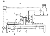
図1は本発明の一実施形態に係る塗布装置であるダイコータ11の概略正面図、図2は高さ測定手段4の概略側面図、図3はダイコータ11の平面図である。
図1に示すように、ダイコータ11は、基材に相当する基板9を保持する保持手段である載置台1、塗布手段2、載置台1と塗布手段2を相対移動させる移動手段3、高さ測定手段4、演算手段であるデータ処理器5、コントローラー7および塗液供給手段8を有している。 図1において、移動手段3は、架台3a、ナット3b、ボールねじ3c、サーボモータ3dおよびガイド3eを有する。架台3a上で枚葉の基板9が、保持手段である載置台1の上面1aに吸着保持される。載置台1は、ガイド3eに支持されていると共にナット3bを介してボールねじ3cに螺合されており、サーボモータ3dの正逆転に伴ってガイド3eに案内されて実線で示す位置Aと、2点鎖線で示す位置Bとの間を往復動することができる。この往復動は、コントローラー7によって制御される。なお、コントローラー7は、上述のように通常の塗布を行うための制御機能だけではなく、後述のように第1の異常処理手段および第2の異常処理手段としての機能を兼ね備えている。 塗液供給手段8は、塗液タンク8aと、塗液タンク8a内の塗液を送出する塗液ポンプ8bと、これら塗液タンク8aと塗液ポンプ8bとを接続する配管8cと、塗液ポンプ8bと塗布手段2を接続する配管8dとを備えている。塗液タンク8aは、好ましくは密閉型のタンクからなり、内部は空気や不活性ガス(たとえば、窒素ガス)によって0.02〜1MPa程度の圧力に加圧されていることが好ましい。また、塗液ポンプ8bは、ピストンでシリンジ内の液を押し出す方式のシリンジポンプであることが好ましいが、ギアポンプやダイアフラムポンプ等の定容量ポンプであってもよく、また、空気圧で圧送してもよい。この塗液ポンプ8bは、コントローラー7からの信号に基づいて作動する。
FIG. 1 is a schematic front view of a
As shown in FIG. 1, the
塗布手段2は、移動手段3の架台3aに取り付けられた支柱2aと、この支柱2aに取り付けられたガイド2bと、このガイド2bに案内されるホルダ2cと、このホルダ2cに装着された、塗液供給手段8の配管8dに接続されたスリットダイ2dとを有する。ホルダ2cには、サーボモータ2eによって駆動されるボールねじ2fが螺合されており、コントローラー7からの信号に基づいてサーボモータ2eが正逆転すると、ホルダ2cがガイド2bに案内されて昇降し、それに伴ってスリットダイ2dが昇降するようになっている。すなわち、スリットダイ2dの昇降に伴ってスリットダイ2dと基板9との間隙を任意に変えることができる。
The application means 2 includes a
本発明の塗布方法においては、保持手段である載置台1に保持された基材である基板9と塗布手段2とを相対移動させながら塗液を塗布手段2より基板9上に押し出すことによって塗布を行う。 In the coating method of the present invention, coating is performed by extruding the coating liquid onto the substrate 9 from the coating means 2 while relatively moving the substrate 9 and the coating means 2 held by the mounting table 1 as the holding means. I do.
なお、図1に示すダイコータ11においては、塗布手段2を固定して基板9を上面1aで保持する載置台1を水平方向に移動することにより両者を相対移動させているが、保持手段である載置台1を固定して塗布手段2を水平方向に移動することによって両者を相対移動させることもできる。また、載置台1と塗布手段2の双方を水平方向に移動しても良い。
In the
高さ測定手段4は、保持手段である載置台1の高さプロファイル、すなわち上面1aの高さプロファイルと、載置台1上の上面1aに被保持面9bで吸着保持された塗布前の基板9の被塗布面9aの高さプロファイルと、および塗布後の基板9上の塗液の塗布膜の高さプロファイルと、を測定する高さ検出器4aが、高さ検出器取り付け支柱4bに取り付けられている。なお基板9の被塗布面9aは、基板9上でダイコータ11によって塗液が塗布されて塗布膜が形成される面、被保持面9bは被塗布面9aの反対側の面で、載置台1の上面1aと密着して対面する面と定義される。
The height measuring unit 4 includes a height profile of the mounting table 1 serving as a holding unit, that is, a height profile of the
さらに、高さ検出器4aで得られる高さプロファイルデータの収集、記憶、演算を行い、後述の第1の演算手段および第2の演算手段として機能するとともに、測定したデータより異物がないかの判別を行うデータ処理器5と、測定した高さプロファイルを表示する表示器6を有している。
Furthermore, the height profile data obtained by the
本発明の塗布方法においては、基材である基板9が載置される前に、まず保持手段である載置台1の高さプロファイルを高さ測定手段4を用いて測定する。次に基板9を載置台1上に搬入、吸着保持する。その後、載置台1上の上面1aに被保持面9bで保持された基板9の被塗布面9aの高さプロファイルを高さ測定手段4を用いて測定し、データ処理器5を用いて、載置台1の高さプロファイルおよび基板9の被塗布面9aの高さプロファイルから基板9の厚さプロファイルを算出し、算出結果から異物の有無を判定する。この際、データ処理器5は上述の第1の演算手段として機能する。このようにして算出した結果から異物の有無を判定して異常があれば異常処理を行う。具体的には、データ処理器5を用いた判定の結果、異物があると判別された場合はコントローラー7に信号が送られ、直ちに塗布動作が停止される。この際、コントローラー7は上述の第1の異常処理手段として機能する。
In the coating method of the present invention, before the substrate 9 as a base material is placed, first, the height profile of the placing table 1 as a holding means is measured using the height measuring means 4. Next, the substrate 9 is carried onto the mounting table 1 and held by suction. Thereafter, the height profile of the
なお、高さ検出器4aは高さ検出器取り付け支柱4bに基板9の塗布幅方向に複数個配置されるが、図2に示すように、高さ検出器4aは基材の塗布幅方向全幅に渡って配置されることが好ましい。
A plurality of
そして載置台1を塗布方向に移動させることにより、高さ検出器4aの直下を通過する載置台1の上面1a、載置台1に吸着保持された基板9の被塗布面9a、および基板9上の塗布膜の各々の高さプロファイルを塗布方向にわたって得ることができる。
Then, by moving the mounting table 1 in the coating direction, the
高さ検出器4aは、レーザ式、静電容量式、超音波式等の非接触式であるのが好ましく、特に、外乱の影響を受けにくいレーザフォーカス式であるのが好ましい。レーザフォーカス式とは、レーザの反射光が通過する対物レンズを高速で往復動させ、反射光をピンポイントで受光したときの対物レンズの位置から被測定物体との距離を知ることができるものである。
The
なお、載置台1の高さプロファイル、すなわち上面1aの高さプロファイルの代わりに、上面1aと密着して対面している基板9の被保持面9bの高さプロファイルを高さ検出器4aで測定して、被保持面9bの高さプロファイルと被塗布面9aの高さプロファイルから基板9の厚さプロファイルを算出し、算出結果から異物の有無を判定するようにしてもよい。載置台1の高さプロファイルを測定する時に、測定ライン上に基板9吸着用の吸着穴や吸着溝があると、
レーザ光の反射光が散乱し、測定が不安定となり、はなはだしい場合は測定不能に陥ってしまう。載置台1の高さプロファイルの代わりに、基板9の被保持面9bの高さプロファイルを測定するようにすると、載置台1の上面1aの状態に影響されないでどの位置でも安定して測定できるので、より好ましい。なお、基板9の被保持面9bの高さプロファイルは、載置台1の高さプロファイルの代わりとなるので、載置台1の上面1aのゴミ等の異物と、基板9の被保持面9bのゴミ等の異物とを完全に取り除いた状態で、載置台1に基板9を吸着保持させた状態で測定したものを、以降の基板9の厚さプロファイルの算出に使用するようにする。これによって、基板9と載置台1の間に異物がある場合に、基板9の厚さプロファイルが異常な値を示すので、異物を検知することができる。
Instead of the height profile of the mounting table 1, that is, the height profile of the
The reflected light of the laser beam is scattered, the measurement becomes unstable, and in the worst case, the measurement becomes impossible. If the height profile of the supported
なお基板9の被保持面9bの高さプロファイルは、高さ検出器4aのレーザ光を基板9の被塗布面9aを通過させて被保持面9bに照射し、その反射光より測定することになるので、基板9は透明か半透明でレーザ光が基板9の被保持面9bに達するとともに被保持面9bでの反射光が高さ検出器4aで受光できるものであることが好ましい。
The height profile of the held
載置台1の傾きやうねり、載置台1を移動させるガイド3eの傾きやうねり、および高さ検出器4aの測定精度に経時変化が無い場合は、得られる高さプロファイルは同じで変化はないので、載置台1の高さプロファイルや基板9の被保持面9bの高さプロファイルの測定は、塗布前の準備作業時に1回だけ実施してもよく、さらには例えば1ヶ月や半年に1回、定期的に測定してもよい。
If there is no change over time in the inclination and undulation of the mounting table 1, the inclination and undulation of the
また、塗布膜の高さプロファイルの測定を行わない場合は、高さ検出器4aは、接触式の変位計の検出部よりエアを吹き出させることによって、被検出物である載置台1上または基板9上で検出部を浮上させ、検出部の位置変化を検知して高さを測定するものを用いてもよい。
When the measurement of the height profile of the coating film is not performed, the
次に、高さ検出器4aを配置するピッチについて説明する。
Next, the pitch at which the
基板9と載置台1の間に異物が挟まれていると、図2で示されるように異物10の球相当径d以上となる基板隆起部長さL2にわたって基板9が隆起する。従って、基板隆起部長さL2未満のピッチで高さ検出器4aを配置すれば、異物による隆起部分が基板9の塗布幅方向のどこにあっても検知できるので、載置台1上の基板を塗布方向に移動させることにより、基板全面にわたって基板9と載置台1の間に挟まれている異物を検知できる。さらに高さ検出器4aの測定範囲長さがL1である場合は高さ検出器4aの配置ピッチは(L2+L1)未満であれば良く、より少ない数の高さ検出器4aで基板全面にわたって、基板9と載置台1の間に挟まれた異物の有無を検知することができる。
When a foreign object is sandwiched between the substrate 9 and the mounting table 1, the substrate 9 rises over the substrate raised portion length L2 that is equal to or larger than the sphere equivalent diameter d of the
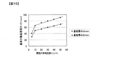
図15は、基板9と載置台1の間にビーズを挟み込んだモデルテストの結果を示したグラフである。図15には、基板9として厚さが2mmと3mmのガラス基板を用いた時の、異物10の球相当径dと、その異物10を基板9と載置台1の間に挟み込んだ場合に隆起する基板隆起部長さL2の関係を実際に測定した結果を示す。
FIG. 15 is a graph showing the results of a model test in which beads are sandwiched between the substrate 9 and the mounting table 1. In FIG. 15, when a glass substrate having a thickness of 2 mm and 3 mm is used as the substrate 9, the sphere equivalent diameter d of the
ここで、異物のモデルとしてには直径が5μm、10μm、20μm、30μm、40μm、50μm径のガラスビーズを用いて、各ガラスビーズを厚さ2mm、3mmの各々のガラス基板と載置台の間に挟んでガラス基板を吸着保持し、その状態でガラスビーズの上部をレーザフォーカス式の高さ検出器を走査させて、0.1mm間隔で隆起部分の高さ変化を実測している。 Here, as a foreign material model, glass beads having diameters of 5 μm, 10 μm, 20 μm, 30 μm, 40 μm, and 50 μm were used, and each glass bead was placed between each glass substrate having a thickness of 2 mm and 3 mm and the mounting table. A glass substrate is adsorbed and held between the glass beads, and the upper portion of the glass beads is scanned by a laser focus type height detector to measure the height change of the raised portions at intervals of 0.1 mm.
なお基板隆起部長さL2とは、図2に示すように、平坦な部分から0.1μm以上連続して高さが盛り上がる山部分の範囲の長さをさす。 As shown in FIG. 2, the substrate raised portion length L2 refers to the length of a range of a mountain portion where the height continuously rises 0.1 μm or more from a flat portion.
図15より、例えばガラス基板の厚さが2mmの時に、ガラス基板と載置台の間に異物の球相当径dが10μmである異物が挟まれていると、基板隆起部長さL2 50mmにわたってガラス基板が隆起するが、基板厚さが3mmの時は同じ異物の球相当径dが10μmの異物でも基板隆起部長さL2 65mmにわたってガラス基板が隆起する。また、異物の球相当径dが5μmから10μmの範囲では、異物の球相当径dが5μm大きくなると、基板隆起部長さL2は20mm大きくなるが、異物の球相当径dが10μmから60μmの範囲では異物の大きさdが50μm大きくなる間に、基板隆起部長さL2は20mm大きくなっている。 From FIG. 15, for example, when a glass substrate has a thickness of 2 mm and a foreign object having a sphere equivalent diameter d of 10 μm is interposed between the glass substrate and the mounting table, the glass substrate extends over a substrate raised portion length L2 of 50 mm. However, when the thickness of the substrate is 3 mm, the glass substrate rises over the substrate raised portion length L2 of 65 mm even if the same foreign matter has a sphere equivalent diameter d of 10 μm. In addition, when the equivalent sphere diameter d of the foreign matter is in the range of 5 μm to 10 μm, when the equivalent sphere diameter d of the foreign matter is increased by 5 μm, the substrate raised portion length L2 is increased by 20 mm, but the equivalent sphere diameter d of the foreign matter is in the range of 10 μm to 60 μm. Then, while the size d of the foreign matter is increased by 50 μm, the substrate raised portion length L2 is increased by 20 mm.
以上の結果より、異物の球相当径dが10μm以上の場合、厚さ2mm以上のガラス基板を用いた場合、積載台とガラス基板の間に異物を挟み込んだ際の基板隆起部長さL2は50mm以上となるので、高さ検出器をこれに応じたピッチで塗布幅方向に配置すれば基板全面に渡って比較的容易に検知できる。 From the above results, when the equivalent spherical diameter d of the foreign material is 10 μm or more, when a glass substrate having a thickness of 2 mm or more is used, the length L2 of the substrate protruding portion when the foreign material is sandwiched between the loading table and the glass substrate is 50 mm. As described above, if the height detectors are arranged in the coating width direction at a pitch corresponding to the height detectors, the entire surface of the substrate can be detected relatively easily.
ガラス基板の全面にわたって隆起部分を検知するための高さ検出器の配置ピッチは前記の通り(L2+L1)未満である。ここで例えばレーザフォーカス式の高さ検出器を用いるのであれば、測定範囲の長さL1は測定スポット径と等しくなるので、数μm程度であり、長さL1はほぼ0とみなすことがきるできる。したがって、レーザフォーカス式の高さ検出器を用いて厚さ2mmのガラス基板と載置台の間に挟まった50μm以上の異物をガラス基板の全面にわたって検知するには、高さ検出器をL2+L1=70+0=70mm未満のピッチで配置すればよい。また、長さが10mmのスリットレーザ光と、これに対応した長さを有する受光素子が備えられた高さ検出器を使う場合は、高さ検出器の測定範囲の長さL1=10mmとなるので、厚さ2mmのガラス基板と載置台の間に挟まった球相当径50μm以上の異物をガラス基板の全面にわたって異物を検知するには、高さ検出器をL2+L1=70+10=80mm未満のピッチで配置すればよい。 The arrangement pitch of the height detectors for detecting the raised portions over the entire surface of the glass substrate is less than (L2 + L1) as described above. Here, for example, if a laser focus type height detector is used, the length L1 of the measurement range is equal to the measurement spot diameter, so it is about several μm, and the length L1 can be regarded as almost zero. . Therefore, in order to detect a foreign matter of 50 μm or more sandwiched between a glass substrate having a thickness of 2 mm and a mounting table using a laser focus type height detector, the height detector is L2 + L1 = 70 + 0. = What is necessary is just to arrange | position with the pitch of less than 70 mm. When a height detector provided with a slit laser beam having a length of 10 mm and a light receiving element having a length corresponding to the slit laser beam is used, the length L1 of the measurement range of the height detector is 10 mm. Therefore, in order to detect foreign matter having a spherical equivalent diameter of 50 μm or more sandwiched between a glass substrate having a thickness of 2 mm and a mounting table over the entire surface of the glass substrate, the height detector is set at a pitch of less than L2 + L1 = 70 + 10 = 80 mm. What is necessary is just to arrange.
プラズマディスプレイ用部材を製造には厚さ2mm程度のガラス基板で10μm〜40μm程度の大きさの異物を検知する必要があるので、高さ検出器を配置するピッチは好ましくは40mm〜50mm程度である。ピッチが50mmより長いと異物の球相当径dが10μm程度の異物を安定してガラス基板の全面にわたって検知することができず、またピッチが40mmより短いと、必要となる高さ検出器の配置数が多くなって設備コストが増大してしまう。 In order to manufacture a plasma display member, it is necessary to detect a foreign substance having a size of about 10 μm to 40 μm with a glass substrate having a thickness of about 2 mm. Therefore, the pitch for arranging the height detector is preferably about 40 mm to 50 mm. . If the pitch is longer than 50 mm, it is impossible to stably detect the foreign matter having a spherical equivalent diameter d of about 10 μm over the entire surface of the glass substrate, and if the pitch is shorter than 40 mm, the required height detector is disposed. The number increases and the equipment cost increases.
厚さが大きく異なるガラス基板や異なる材質の基材を用いる場合は、上記と同様に異物の球相当径と、基材と保持手段との間に異物を挟み込んだ時の基材の隆起部分の長さの関係を測定しておくことが肝要である。これによって高さ検出器を配置するピッチを適切に決めることができる。 When using a glass substrate with a significantly different thickness or a base material of a different material, the sphere equivalent diameter of the foreign material and the raised portion of the base material when the foreign material is sandwiched between the base material and the holding means as described above. It is important to measure the length relationship. This makes it possible to appropriately determine the pitch at which the height detector is disposed.
さて、上述の高さ測定手段4による載置台1の高さプロファイル、載置台1の上面1aに吸着保持された塗布前の基板9の被塗布面9aの高さプロファイル、および塗布後の塗液の塗布膜表面の高さプロファイルの測定は、載置台1を基板9に対して塗布方向(図1の載置台1の移動方向)に移動させることで行うことができるが、高さ測定手段4による測定開始、終了や、データ処理器5によるデータの収集開始、終了等、高さ測定手段4の動作はコントローラー7によって制御される。収集されたデータはデータ処理器5に記憶され、さらに演算処理等が行われ、処理結果が表示器6に表示される。
Now, the height profile of the mounting table 1 by the height measuring means 4 described above, the height profile of the
コントローラー7は前述したとおり、移動手段3における載置台1の往復動の制御と、塗液供給手段8における塗液ポンプ8bの制御と、塗布手段2におけるスリットダイ2dと基板9との間隙の制御と、高さ測定手段4におけるデータ処理器5によるデータの収集開始と終了の制御と、高さ測定手段4における異物を判別して塗布動作続行または停止の制御とを行い、さらに、スリットダイ2dの昇降や塗液供給手段8による塗液の供給開始、終了の制御も行う。
As described above, the
また、本発明の塗布方法においては、塗布手段2より基材9の被塗布面9aに塗液を塗布して塗布膜を形成した後に、高さ測定手段4を用いて塗布膜の高さプロファイルを測定し、基材9の被塗布面9aの高さプロファイルおよび基材上の塗布膜の高さプロファイルを演算処理して塗布膜の厚さプロファイルを算出し、算出結果から塗布の異常の有無を判定して異常があれば異常処理を行うことがこのましい。この際、データ処理器5は第2の演算手段、コントローラー7は第2の異常処理手段として機能する。
In the coating method of the present invention, the coating film is coated on the
さて、上述したダイコータ11を用いた本発明の塗布方法は、載置台1の高さプロファイルを測定する第1の工程(以下、工程1という)、基板9の被塗布面9aの高さプロファイルを測定する第2の工程(以下、工程2という)、基板9に塗液を塗布する第3の工程(以下、工程3という)、必要に応じて基板9の塗液の塗布膜表面の高さプロファイルを測定する第4の工程(以下、工程4という)、塗布した基板9を搬出する第5の工程(以下、工程5という)の4つ(工程1〜3および5)または5つ(工程1〜5)の工程からなる。次に図1〜図13を参照しながら各工程ごとに本発明の塗布方法の好ましい態様を詳細に説明する。
Now, in the coating method of the present invention using the
なお図3において高さプロファイル測定ラインPmi(i=1〜n)で示すそれぞれの線上に高さ検出器4aが配置されており、載置台1の塗布方向の移動により、載置台1、載置台1上の基板9、塗布膜表面の高さを測定することができる。高さプロファイル測定ラインPmi(i=1〜n)で示す複数からなる線は図2のL2+L1で示される距離未満のピッチ間隔で基板9の全面を網羅するように配列され、また各線上での測定位置はあらかじめ設定される。
In addition, the
工程1:載置台1の高さプロファイルの測定
本工程では載置台1の高さプロファイルを測定する。
Step 1: Measurement of Height Profile of Mounting Table 1 In this step, the height profile of the mounting table 1 is measured.
まず、移動手段3のサーボモータ3dを駆動し、ボールネジ3cを回転させて基板9を載置していない載置台1を位置Aから位置Bまで一定速度で塗布方向に移動させる。載置台1が高さ検出器4aの下を通過するとき、それぞれの高さ検出器4aが高さプロファイル測定ラインPmi(i=1〜n)の線上における塗布方向の載置台1の高さプロファイルShm0i(i=1〜n)を測定する。なお、高さを測定する塗布方向の載置台1上の位置や個数はあらかじめ与えられる。
First, the
Pmi(i=1〜n)に示す線上で測定された載置台1の高さプロファイルShm0i(i=1〜n)はデータ処理器5に収集、記憶され、表示器6にグラフ表示される。
The height profile Shm0i (i = 1 to n) of the mounting table 1 measured on the line indicated by Pmi (i = 1 to n) is collected and stored in the
載置台1の高さプロファイルShm0iの一例を図4に示す。高さプロファイルは全体に右上がりで、かつうねりが見られる。これは載置台1の傾きやうねりと、載置台1を移動させるガイド3eの傾きやうねりが、本来の高さプロファイルに重ね合わされた状態で測定されるためである。
An example of the height profile Shm0i of the mounting table 1 is shown in FIG. The height profile rises to the right and has undulations. This is because the inclination and the undulation of the mounting table 1 and the inclination and the undulation of the
基板9を載置台1に吸着保持するための吸着孔が高さプロファイル測定ラインPmi(i=1〜n)のライン上にあった場合、吸着孔の部分では高さ値が大きく乱れたり測定不能となるので、高さプロファイルShm0i(i=1〜n)の中で所定以上に急激に変化するデータや測定不能となる部分があれば、その前後の高さ値に置換する処理を行うことも好ましい。 When the suction hole for sucking and holding the substrate 9 on the mounting table 1 is on the height profile measurement line Pmi (i = 1 to n), the height value is greatly disturbed or cannot be measured at the suction hole portion. Therefore, if there is data that changes abruptly more than a predetermined value in the height profile Shm0i (i = 1 to n) or a portion that cannot be measured, the height profile before and after that may be replaced. preferable.
また、載置台1の上面1aに付着しているゴミと、基板9に付着しているゴミとを完全に取り除いた状態で、載置台1の上面1aに基板9を被保持面9bで吸着保持させて、高さ検出器4aのレーザ光を基板9の被塗布面9aを通過させて被保持面9bに照射し、その反射光より被保持面9bの高さプロファイルを測定し、載置台1の上面1aの高さプロファイルとして用いてもよい。
Further, the substrate 9 is sucked and held by the held
なお工程1では、載置台1の傾きやうねり、載置台1を移動させるガイド3eの傾きやうねり、および高さ検出器4aの測定精度に経時変化が無い場合は、得られる高さプロファイルは同じで変化はないので、載置台1の高さプロファイルや基板9の被保持面9bの高さプロファイルの測定は、塗布前の準備作業時に1回だけ実施してもよく、さらには例えば1ヶ月や半年に1回、定期的に測定してもよい。 工程2:基板9の被塗布面9aの高さプロファイルの測定
本工程では載置台1の所定の位置に吸着保持された基板9の被塗布面9aの高さプロファイルを工程1で測定した同じ位置で測定する。また、載置台1の高さプロファイルおよび基板9の被塗布面9aの高さプロファイルから基板9の厚さプロファイルを算出し、算出結果から異物の有無を判定し、異常があれば異常処理を行う。
In
まず、基板9を載置台1の所定の位置におき、図示しない吸着孔からの吸引により基板9を載置台1に吸着保持させる。 First, the substrate 9 is placed at a predetermined position on the mounting table 1, and the substrate 9 is sucked and held on the mounting table 1 by suction from a suction hole (not shown).
続いて、移動手段3のサーボモータ3dを駆動し、ボールネジ3cを回転させて載置台1を位置Aから位置Bまで一定速度で塗布方向に移動させる。基板9が高さ検出器4aの下を通過するとき、それぞれの高さ検出器4aが高さプロファイル測定ラインPmi(i=1〜n)の線上の工程1で測定した同じ位置で、塗布方向の基板9の被塗布面9aの高さプロファイルShm1i(i=1〜n)を測定する。なお、高さを測定する塗布方向の載置台1上の位置や個数は、工程1で測定した同じ位置と個数があらかじめ与えられる。
Subsequently, the
高さプロファイル測定ラインPmi(i=1〜n)に示す線上の工程1と同じ位置で測定された基板9の被塗布面9aの高さプロファイルShm1i(i=1〜n)は、データ処理器5に収集、記憶され、表示器6にグラフ表示される。
The height profile Shm1i (i = 1 to n) of the
基板9の被塗布面9aの高さプロファイルShm1iの一例を図5に示す。図5に示す基板9の被塗布面9aの高さプロファイルも図4に示した載置台1の高さプロファイルShm0iと同様に、全体に右上がりでかつうねりが見られる。これは載置台1の傾きやうねりと、載置台1を移動させるガイド3eの傾きやうねりが、本来の高さプロファイルに重ね合わされた状態で測定されるためである。
An example of the height profile Shm1i of the
次にデータ処理器5では基板9の被塗布面9aの高さプロファイルShm1i(i=1〜n)から載置台1の高さプロファイルShm0i(i=1〜n)を差し引く演算処理が行われて、基板厚さプロファイルThm1i(i=1〜n)が算出される。
Next, the
それぞれ演算処理された結果は表示器6にグラフ表示される。基板厚さプロファイルThm1iの一例を図6に示す。載置台1と基板9の被塗布面9aの高さの測定に含まれる載置台1の傾きやうねりと、載置台1を移動させるガイド3eの傾きやうねりが引き算によって除外されるので、図6では真の基板厚さプロファイルだけが示される。
The result of each arithmetic processing is displayed as a graph on the display 6. An example of the substrate thickness profile Thm1i is shown in FIG. Since the tilt and undulation of the mounting table 1 included in the measurement of the height of the
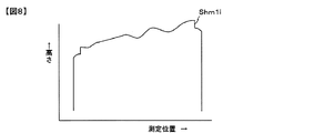
図4,5,6は基板9の表面や裏面に異物がない場合であるが、異物があった場合を図7〜9を参照して説明する。 4, 5, and 6 are cases where there is no foreign matter on the front and back surfaces of the substrate 9, the case where there is a foreign matter will be described with reference to FIGS. 7 to 9.
図7は基板9と載置台1との間に異物10を挟み込んだ状態を示した図である。図7の状態における基板9の被塗布面9aの高さプロファイルShm1iの一例を図8に示す。図8では異物による隆起が含まれているものの、一見して異物によるものなのか載置台1のうねりによるものなのか判別できない。図9は図7の状態における基板9の厚さプロファイルの一例を示したものである。これは図8に示した基板9の被塗布面9aの高さプロファイルShm1iから、図4に示した載置台1の高さプロファイルShm0iを差し引いて求めたものである。
FIG. 7 is a view showing a state in which the
図9では厚さ異常部分a1が存在していることから、異物10が挟み込まれていることにより基板9が隆起していることがわかる。このように、基板9の厚さプロファイルThm1iにより異物の有無を明確に判定できる。データ処理器5では基板の規格厚さに対して図9中の1点鎖線で示すようなスレッシュホールドレベルを設定して、スレッシュホールドレベルを越えたデータがあれば異物ありと判断し、コントローラー7へ異常信号を送る。コントローラー7は異常信号を受けてから異常警報を発して塗布基板の製造工程を停止させる。オペレータは異常警報を確認してから、異物を取り除く。その後にコントローラー7はオペレータからの再スタート指令を受けて製造工程は再開される。
In FIG. 9, since the abnormal thickness portion a <b> 1 exists, it can be seen that the substrate 9 is raised due to the
異物が検知されると自動的に製造工程は停止されるので、スリットダイ2dが異物や異物によって隆起した基板9に衝突することがなくなり、その結果、欠陥品を製造したり、製造工程を止めて予備のスリットダイに交換するなどの作業がなくなり、製造コストを上昇させたり、稼働率を低下させたりすることは無くなる。
Since the manufacturing process is automatically stopped when a foreign object is detected, the
工程3:基板9への塗液の塗布
本発明の塗布方法においては、保持手段である載置台1に保持された基材である基板9と塗布手段2とを相対移動させながら塗液を塗布手段2より基板9上に押し出すことによって塗布を行うが、塗布の際、基板の被塗布面9aの高さプロファイルを元に基板9とスリットダイ2dの間隙を制御しながら塗布を行うことが好ましい。その方法を以下で説明する。
Step 3: Application of coating liquid to substrate 9 In the coating method of the present invention, the coating liquid is applied while relatively moving the substrate 9 and the coating means 2 held by the mounting table 1 as the holding means. The coating is performed by extruding onto the substrate 9 from the means 2, and it is preferable to perform the coating while controlling the gap between the substrate 9 and the slit die 2d based on the height profile of the
先ず、工程2で得られた基板9の被塗布面9aの高さプロファイルShm1iをもとに、塗布手段2のスリットダイ2dと基板9との間隙が所望の一定値になるよう、ダイコータ11のコントローラー7からの指令によりサーボモータ2eを駆動し、スリットダイ2dを下降させる。
First, based on the height profile Shm1i of the
次に、移動手段3の載置台1を、基板9を載置したまま図1の位置Aから位置Bに向かって一定速度で移動させる。コントローラー7が、基板9の塗布開始部位がスリットダイ2dの吐出口の直下に到達したことを検知したときに、塗液供給手段8の塗液ポンプ8bに塗液の供給開始を指令する。これによって、スリットダイ2dから塗液が吐出され、基板9への塗布が開始される。塗液ポンプ8bによるスリットダイ2dへの塗液の供給量は、コントローラー7に設定された目標とする膜厚に応じて定められる。
Next, the mounting table 1 of the moving
基板9の塗布終了部位がスリットダイ2dの吐出口の直下に到達すると、コントローラー7から塗液ポンプ8bに停止指令が送られ、スリットダイ2dからの塗液の吐出が停止されるとともにスリットダイ2dが上昇せしめられる。塗布を開始して終了するまでの間、基板9の被塗布面9aの高さプロファイルShm1iをもとに、塗布手段2のスリットダイ2dと基板9との間隙が常に所望の一定値になるよう、ダイコータ11のコントローラー7からの指令によりサーボモータ2eを駆動し、スリットダイ2dの高さを制御することが好ましい。
When the application end portion of the substrate 9 reaches just below the discharge port of the slit die 2d, a stop command is sent from the
載置台1は、位置Bまで移動した後、位置Aに復動する。 The mounting table 1 moves back to the position A after moving to the position B.
工程4:基板9に塗布された塗液の塗布膜の高さプロファイルの測定
本工程では、塗布された基板9の塗液の塗布膜の高さプロファイルを測定し、塗布膜の厚さプロファイルを算出する。また、算出結果から塗布の異常の有無を判定し、異常があれば異常処理を行う。
Step 4: Measurement of the height profile of the coating film of the coating liquid applied to the substrate 9 In this step, the height profile of the coating film of the coating liquid applied to the substrate 9 is measured, and the thickness profile of the coating film is determined. calculate. Also, the presence or absence of application abnormality is determined from the calculation result.
まず、移動手段3のサーボモータ3dを駆動し、ボールネジ3cを回転させて載置台1を位置Aから位置Bまで一定速度で塗布方向に移動させる。基板9が高さ検出器4aの下を通過するとき、高さ検出器4aが高さプロファイル測定ラインPmi(i=1〜n)の線上の工程1で測定した同じ位置で、塗布方向の基板9の塗布膜表面の高さプロファイルShm2i(i=1〜n)を測定する。なお、高さを測定する塗布方向の載置台1上の位置や個数は、工程1で測定した同じ位置と個数があらかじめ与えられる。
First, the
高さプロファイル測定ラインPmi(i=1〜n)に示す線上の工程1と同じ位置で測定された基板9の塗布膜表面の高さプロファイルShm2i(i=1〜n)は、データ処理器5に収集、記憶される。
The height profile Shm2i (i = 1 to n) of the coating film surface of the substrate 9 measured at the same position as in
次にデータ処理器5では塗布方向の基板9の塗布膜表面の高さプロファイルShm2i(i=1〜n)から基板9の被塗布面9aの高さプロファイルShm1i(i=1〜n)を差し引く演算処理が行われて、塗布膜の厚さプロファイルThm2i(i=1〜n)が算出される。
Next, the
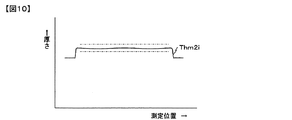
算出された塗布膜の厚さプロファイルThm2i(i=1〜n)は表示器6にグラフ表示される。塗布膜の厚さプロファイルThm2iの一例を図10に示す。 The calculated coating film thickness profile Thm2i (i = 1 to n) is displayed as a graph on the display 6. An example of the thickness profile Thm2i of the coating film is shown in FIG.
図10の1点鎖線で示すような設定された膜厚に対してスレッシュホールドレベルを設定して、スレッシュホールドレベルを越える部分があればデータ処理器5で膜厚異常と判断し、コントローラー7へ異常信号を送る。コントローラー7は異常信号を受けてから異常警報を発して塗布基板の製造工程を停止させる。
A threshold level is set for the set film thickness as shown by the one-dot chain line in FIG. 10, and if there is a portion exceeding the threshold level, the
オペレータは異常警報により膜厚異常を現認してから、次のアクションのために膜厚異常の原因はスリットダイ2dの異常なのか、基板9上または基板9と載置台1との間に異物があるためなのかを究明する。以下、その判断手法の例を説明する。 After the operator recognizes the film thickness abnormality by the abnormality alarm, the cause of the film thickness abnormality is the abnormality of the slit die 2d for the next action, or the foreign matter on the substrate 9 or between the substrate 9 and the mounting table 1 Investigate whether it is because there is. Hereinafter, an example of the determination method will be described.
図11は、塗布膜の厚さプロファイルThm2iの別の例を示した図である。ここでは塗布膜の厚さが厚さ異常部分a2において凹みがあり、スレッシュホールドレベルを下回っているが、凹みはスリットダイ2dの該当部分が詰まって塗液が吐出されなかったことにより生じたものなのか、基板9上の異物、または基板9と載置台1の間に異物が挟まって基板9の当該部分が隆起していることによって生じたものなのかは、これだけでは判断が困難である。 FIG. 11 is a diagram showing another example of the thickness profile Thm2i of the coating film. Here, the thickness of the coating film has a dent in the abnormal thickness portion a2, which is below the threshold level, but the dent was caused by the corresponding portion of the slit die 2d being clogged and the coating liquid not being discharged. It is difficult to determine whether this is caused by foreign matter on the substrate 9 or when the portion of the substrate 9 is raised with the foreign matter sandwiched between the substrate 9 and the mounting table 1.
そこで、同じ高さプロファイル測定ラインPmiにおける基板9の厚さプロファイルを調べる。図12に、図11と同じ高さプロファイル測定ラインPmiにおける基板の厚さプロファイルThm1iの一例を示す。図12には、図11において凹みが存在した厚さ異常部分a2に相当する位置に隆起部分a3が存在する。隆起部分a3の厚さは1点鎖線で示すスレッシュホールドレベル内ではあるが、載置台1と基板9の間に異物があり基板9が隆起しているのが判る。従って、図11のa2の部分の膜厚の凹みは、a2の部分に基板9と載置台1の間に小さな異物を挟み込んだために、基板9がa2の部分で隆起してスリットダイ2dと基板9の間隙が狭くなり、塗液の塗布が妨げられたために生じたことがわかる。オペレータは以上の結果で異物が原因と判別できた場合は異物を取り除いたり、載置台1の清掃を行う。 Therefore, the thickness profile of the substrate 9 in the same height profile measurement line Pmi is examined. FIG. 12 shows an example of the substrate thickness profile Thm1i in the same height profile measurement line Pmi as in FIG. In FIG. 12, a raised portion a3 is present at a position corresponding to the abnormal thickness portion a2 where the dent was present in FIG. Although the thickness of the raised portion a3 is within the threshold level indicated by the one-dot chain line, it can be seen that there is a foreign object between the mounting table 1 and the substrate 9, and the substrate 9 is raised. Accordingly, since the dent in the film thickness at the portion a2 in FIG. 11 has a small foreign object sandwiched between the substrate 9 and the mounting table 1 at the portion a2, the substrate 9 rises at the portion a2 and the slit die 2d. It can be seen that this occurred because the gap between the substrates 9 became narrow and the application of the coating liquid was hindered. If the operator can determine that the cause of the foreign matter is the above result, the operator removes the foreign matter or cleans the mounting table 1.
また、図13は図11と同じ高さプロファイル測定ラインPmiにおける基板9の厚さプロファイルThm1iの別の例を示しているが、このように基板厚さがフラットである場合は、基板9と載置台1の間に挟み込んだ異物が異常部分a2の凹みの原因ではないので、スリットダイ2dのスリット内の汚れや詰まりなどの点検を行う。
FIG. 13 shows another example of the thickness profile Thm1i of the substrate 9 in the same height profile measurement line Pmi as in FIG. 11, but when the substrate thickness is flat as described above, the substrate 9 and the substrate 9 are mounted. Since the foreign matter sandwiched between the
また、図11のa2の部分はスレッシュホールドレベルを越えている例であるが、スレッシュホールドレベルの範囲内であっても膜厚プロファイルに小さなくぼみがある場合に、本発明の方法により膜厚のくぼみの原因を判別し、基板9とスリットダイ2dとの間隙より小さい異物を取り除いたり、スリットダイ2dを清掃することなどによって、塗布ムラを小さくすることが可能になり、品質や収率が向上して高い生産性を実現できる。 11 is an example in which the threshold level is exceeded, but the film thickness can be reduced by the method of the present invention when the film thickness profile has a small depression even within the threshold level range. By identifying the cause of the dent and removing foreign matter smaller than the gap between the substrate 9 and the slit die 2d or cleaning the slit die 2d, it becomes possible to reduce coating unevenness and improve quality and yield. High productivity.
工程5:塗布した基板9の搬出
本工程では塗布膜厚測定後の基板9を次の工程に搬出する。
塗布を行い、データ処理器5にて膜厚に異常がないと判別された場合は、吸着保持された基板9の吸着を解除し、図示しないロボットハンドなどで位置Bにある載置台1より下流工程へ搬出される。データ処理器5にて膜厚に品質限度を超える異常があったと判別された場合は、コントローラー7より図示しないロボットハンドに指令が送られ、ロボットハンドはその基板を不良品として別な場所に搬出する。基板9の搬出が終了すれば載置台1を位置Bから位置Aに復動させる。
Step 5: Unloading the coated substrate 9 In this step, the substrate 9 after the coating film thickness measurement is unloaded to the next step.
When the
本実施の態様では各工程を逐次実施する例が示されているが、図1および図3に示すダイコータ11では、工程2における基板9の被塗布面9aの高さプロファイルの測定と、工程3における基板9への塗液の塗布は、載置台1の位置Aから位置Bへの同じ移動中に行えるので、工程2と工程3を同時に行って生産タクトタイムを短くすることができる。すなわち、載置台1上に載置された基板9が位置Aからスリットダイ2dで塗布されながら位置Bに移動する時に、高さ検出器4aの直下を通る時に塗布される前の基板9の被塗布面9aの高さプロファイルの測定しながら、工程1であらかじめ記憶させておいた同じ測定位置での載置台1の高さプロファイル、または同じ測定位置での基板9の被保持面9bの高さプロファイルを差し引く演算を逐次行い、異物があると判定された場合は即座に塗布動作を停止させればよい。塗布動作に先行して基板9の被塗布面9aの高さプロファイルの測定を行うので、全ての塗布基板の異物検知を行うことができる。また塗布が安定している場合は、工程4である基板9に塗布された塗液の塗布膜表面の高さプロファイルの測定を、何枚かに1回実施するようにすると更に生産タクトタイムは短縮できる。
In the present embodiment, an example is shown in which each step is sequentially performed. However, in the
上述の実施の態様では載置台1が位置Aにある時に基板9を搬入し、各工程を経た後、載置台1が位置Bにある時に基板9を排出する例が示されているが、基板を載置した載置台1が位置Aからスリットダイ2dで塗布されながら位置Bに移動した後、位置Bから位置Aに移動する時に、工程4である基板9に塗布された塗液の塗布膜表面の高さプロファイルの測定を実施し、位置Aにて基板を排出する方法であっても生産タクトタイムを短くすることができる。 In the above-described embodiment, an example is shown in which the substrate 9 is loaded when the mounting table 1 is at the position A, and after passing through each process, the substrate 9 is discharged when the mounting table 1 is at the position B. When the mounting table 1 on which the substrate is mounted is moved from the position A to the position B while being applied by the slit die 2d, and then moved from the position B to the position A, the coating film of the coating liquid applied to the substrate 9 which is step 4 Even when the surface height profile is measured and the substrate is discharged at the position A, the production tact time can be shortened.
また、図1および図3に示すダイコータ11で、載置台1を位置Aから位置Bに移動するときに工程2である基板9の被塗布面9aの高さプロファイルの測定を実施し、つづけて載置台1を位置Bから位置Aに移動させながら工程3である基板9への塗液の塗布と、工程4である基板9に塗布された塗液の塗布膜表面の高さプロファイルの測定を同時に実施しても生産タクトタイムを短くすることができる。この場合は基板は載置台1が位置Aにある状態で搬入および排出すればよい。
Further, with the
また、本実施の態様では同様に異物の検知するために塗布に用いる基板の規格厚さを基準にスレッシュホールドレベルを設定した例を示しているが、基板9の被塗布面9aの高さプロファイルShm1i(i=1〜n)の平均値を基準に設定してもよい。
Further, in the present embodiment, an example is shown in which the threshold level is set based on the standard thickness of the substrate used for coating in order to detect foreign matter, but the height profile of the
また、本実施の態様では膜厚の異常を検知するために設定された膜厚を基準にスレッシュホールドレベルを設定した例を示しているが、膜厚プロファイルThm2i(i=1〜n)の平均値を基準にしてもよい。 In this embodiment, an example in which the threshold level is set based on the film thickness set for detecting an abnormality in the film thickness is shown, but the average of the film thickness profiles Thm2i (i = 1 to n) is shown. The value may be used as a reference.
以上の実施態様では、塗布液の粘度は3000〜30000mPa・secの範囲で、塗布速度は1〜10m/minの範囲であることが好ましい。高さプロファイル測定ラインPmi上での測定ピッチは好ましくは0.05mm〜10mm、より好ましくは0.1mm〜1mmとする。高さプロファイルの測定速度は1m/min〜30m/minの範囲内で行われることが好ましい。測定ピッチを前記範囲より短くしたり、測定速度を前記範囲より遅くしたりすると、測定時間が著しく増加して、1枚の処理時間が増加してしまい、生産効率が著しく低下する。逆に測定ピッチを前記範囲より長くしたり、測定速度を前記範囲より速くしたりすると、小さな異物や塗布ムラを検知できないことがある。 In the above embodiment, the viscosity of the coating solution is preferably in the range of 3000 to 30000 mPa · sec, and the coating speed is preferably in the range of 1 to 10 m / min. The measurement pitch on the height profile measurement line Pmi is preferably 0.05 mm to 10 mm, more preferably 0.1 mm to 1 mm. The measurement speed of the height profile is preferably performed within a range of 1 m / min to 30 m / min. When the measurement pitch is made shorter than the above range or the measurement speed is made slower than the above range, the measurement time is remarkably increased, the processing time for one sheet is increased, and the production efficiency is remarkably lowered. Conversely, if the measurement pitch is made longer than the above range or the measurement speed is made faster than the above range, small foreign matter or coating unevenness may not be detected.
高さ検出器4aを配置する間隔は前述した通り、図15の特性をもとに、例えば厚さ2mmのガラス基板で10μm以上の異物を検知する場合は、50mm間隔で配置すればよい。
As described above, the intervals at which the
また、以上の実施態様ではガラス基板などの枚葉被塗布部材に対する塗布について説明したが、保持手段にロールを用いて、連続部材であるフィルム、金属シートや金属箔などの部材へ塗布する時にも本発明を適用して、ロールの高さプロファイル、フィルムなどの連続基材の高さプロファイル、塗布膜表面高さプロファイルを測定して、異物や、異物による塗布厚さムラを検知することもできる。 In the above embodiment, the application to the single-wafer coated member such as the glass substrate has been described. However, when applying to a member such as a film, a metal sheet or a metal foil which is a continuous member using a roll as a holding means. By applying the present invention, the height profile of a roll, the height profile of a continuous substrate such as a film, and the coating film surface height profile can be measured to detect foreign matter and coating thickness unevenness due to the foreign matter. .
先ず前工程として、幅(基板幅方向)570mm×長さ(塗布方向)970mm×厚さ2mmのソーダガラス基板上の全面に感光性銀ペーストを5μmの厚さにスクリーン印刷した後で、フォトマスクを用いて露光し、現像および焼成の各工程を経て、ピッチ300μmでストライプ状の3072本の銀電極を形成した。その電極上にガラスとバインダーからなるガラスペーストをスクリーン印刷した後に、焼成して10μm厚さの誘電体層を形成した。 First, as a pre-process, a photosensitive silver paste is screen-printed to a thickness of 5 μm on a soda glass substrate having a width (substrate width direction) of 570 mm × length (application direction) of 970 mm × thickness of 2 mm, and then a photomask The film was exposed to light and subjected to development and baking steps to form 3072 silver electrodes in a stripe shape with a pitch of 300 μm. A glass paste made of glass and a binder was screen-printed on the electrode and then fired to form a dielectric layer having a thickness of 10 μm.
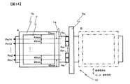
次に図1のダイコータ11で隔壁用のガラスペーストを塗布する基板9の載置台1には幅(基板幅方向)600mm×長さ(塗布方向)1000mmの大きさの物を用いた。図14は実施例における高さ検出手段4aの配置を示した平面図である。高さプロファイルを測定するため、図14に示すように高さプロファイル測定ラインPm1を載置台1端から55mm(=基板端部より40mm)の位置で塗布方向に伸びる線とし、10μm以上の異物を検知できるように40mm間隔の位置で塗布方向に延びる線を高さプロファイル測定ラインPm2、Pm3・・・、Pm14とした。すなわち高さプロファイル測定ラインPm14は高さプロファイル測定ラインPm1と反対側の載置台端から55mm(=高さプロファイル測定ラインPm1と反対側の基板端部より40mm)の位置で塗布方向に延びる線である。それぞれの高さプロファイル測定ラインPmi(i=1〜14)の線の中心に高さ検出器4aとしてスポット径が約2μmのレーザフォーカス式変位計を配置した。すなわち、レーザフォーカス式変位計14台を40mmピッチで基板幅方向に配置した。
Next, an article having a width (substrate width direction) of 600 mm × length (application direction) of 1000 mm was used for the mounting table 1 of the substrate 9 on which the partition wall glass paste was applied by the
それぞれの高さプロファイル測定ラインPmi(i=1〜14)上の測定位置は載置台1の右端部から左端部までの総距離1000mmを0.5mmピッチで分割した2001点で与えた。 The measurement position on each height profile measurement line Pmi (i = 1 to 14) was given by 2001 points obtained by dividing a total distance of 1000 mm from the right end portion to the left end portion of the mounting table 1 at a pitch of 0.5 mm.
高さプロファイルの測定速度となる載置台1と高さ検出器4aの移動速度はともに10m/minとした。
Both the moving speed of the mounting table 1 and the
以上の条件で、先ず第1工程で、高さプロファイル測定ラインPmi(i=1〜14)上の載置台1の高さプロファイルShm10i(i=1〜14)を測定し、記憶させた。 Under the above conditions, first, in the first step, the height profile Shm10i (i = 1 to 14) of the mounting table 1 on the height profile measurement line Pmi (i = 1 to 14) was measured and stored.
次に第2工程では、高さプロファイル測定ラインPmi(i=1〜14)上の基板9の被塗布面9aの高さプロファイルShm1i(i=1〜14)を測定し、記憶させた。
Next, in the second step, the height profile Shm1i (i = 1 to 14) of the
ついで記憶させておいた高さプロファイルShm1i(i=1〜14)とShm0i(i=1〜14)との差分をぞれぞれとって、基板高さを算出し、基板9の表裏に異物がないことを確認した。 Next, the difference between the stored height profiles Shm1i (i = 1 to 14) and Shm0i (i = 1 to 14) is calculated to calculate the substrate height, and foreign matter is placed on the front and back of the substrate 9. Confirmed that there is no.
次に第3工程として、図1の塗布手段2のスリットダイ2dとして基板幅方向の吐出幅550mm、リップ間隙(シム厚さ)500μmのサイズのものを用い、スリットダイ2dの下面とガラス基板上の誘電体層との隙間が350μmになるようにスリットダイ2dを下降させた後に、ガラス粉末と感光性有機成分からなる粘度20000mPa・secの感光性ガラスペーストを塗布厚さ300μmで塗布速度3m/分にて塗布し、隔壁層を形成した。
Next, as a third step, a
次に第4工程では、高さプロファイル測定ラインPmi(i=1〜14)上の基板9の塗布膜表面の高さプロファイルShm2i(i=1〜14)を測定し、記憶させた。 Next, in the fourth step, the height profile Shm2i (i = 1 to 14) of the coating film surface of the substrate 9 on the height profile measurement line Pmi (i = 1 to 14) was measured and stored.
ついで記憶させておいた塗布前後の高さプロファイルShm1i(i=1〜14)とShm2i(i=1〜14)との差分をとって膜厚プロファイルを算出し、異常がないことを確認した。 Then, the film thickness profile was calculated by taking the difference between the height profiles Shm1i (i = 1 to 14) and Shm2i (i = 1 to 14) stored before and after the application, and it was confirmed that there was no abnormality.
次に第5工程として、吸着保持された基板9の吸着を解除し、ロボットハンドで載置台1より下流工程へ搬出した。 Next, as a fifth step, the suction of the substrate 9 held by suction was released, and it was carried out from the mounting table 1 to the downstream step by the robot hand.
後工程として、塗布した基板9を輻射ヒータを用いた乾燥炉で、100℃で20分間乾燥した。乾燥後の隔壁塗布膜厚さ分布を基板9の全面にわたって塗布方向に測定したところ、140μm±3μmの許容範囲以下となった。ついで隣にあった電極間に隔壁が形成されるように設計されたフォトマスクを用いて隔壁層を形成した基板9を露光し、現像と焼成を行ってストライプ状の隔壁を形成した。隔壁の形状はピッチ300μm、線幅50μm、高さ140μmであり、隔壁本数は3073本であった。以上のようにして所定形状の隔壁が形成されたプラズマディスプレイ背面板を得た。 As a post-process, the coated substrate 9 was dried at 100 ° C. for 20 minutes in a drying furnace using a radiation heater. When the partition wall coating film thickness distribution after drying was measured in the coating direction over the entire surface of the substrate 9, it was below the allowable range of 140 μm ± 3 μm. Next, the substrate 9 on which the partition layer was formed was exposed using a photomask designed to form a partition between adjacent electrodes, and development and baking were performed to form a striped partition. The partition walls had a pitch of 300 μm, a line width of 50 μm, a height of 140 μm, and the number of partition walls was 3073. In this way, a plasma display back plate having a predetermined shape of partition walls was obtained.
第1工程は最初の1回のみ実施し、その後、前工程、第2工程〜第5工程、後工程を1000回繰り返したところ、第2工程において100枚目でShm18とShm08の差分の結果に異物による350μm程度の隆起が見られたので、隆起している位置を現物で確認したところ、基板9と載置台1の吸着面との間に異物が挟まっていることが解った。この異物を取り除いて、再度、基板9の被塗布面9aの高さプロファイルを測定して同様に差分をとって見た結果、基板9の表裏に異物がないことを確認し、以降の工程を継続して実施した。
The first step is performed only once for the first time, and then the previous step, the second step to the fifth step, and the subsequent step are repeated 1000 times. In the second step, the difference between Shm18 and Shm08 is obtained at the 100th sheet. Since the uplift of about 350 μm due to the foreign matter was observed, the raised position was confirmed with the actual product, and it was found that the foreign matter was sandwiched between the substrate 9 and the suction surface of the mounting table 1. After removing this foreign matter, again measuring the height profile of the
また、第4工程において200枚目に異常警報が出て、Shm112とShm212との差分の結果に300±5μmに対して300μmより15μm程度薄くなっている箇所が見つかった。膜厚が薄くなっている位置を含むShm112とShm012との差分を見たが異常がみられないので、塗布手段2に異常があると推定し、スリットダイ2dの吐出口をチェックしたところ汚れが見られたため汚れを拭き取るとともに、この基板9は廃棄した。 In the fourth step, an abnormality alarm was issued on the 200th sheet, and a difference between Shm112 and Shm212 was found to be about 15 μm thinner than 300 μm with respect to 300 ± 5 μm. When the difference between Shm112 and Shm012 including the position where the film thickness is thin was observed, no abnormality was found, so it was estimated that there was an abnormality in the coating means 2, and when the discharge port of the slit die 2d was checked, dirt was found. Since it was seen, the dirt was wiped off and the substrate 9 was discarded.
以上のようにして1000枚のうち、999枚の良好な良好な隔壁が形成されたプラズマディスプレイ背面板を得て、さらに、R、G、Bの蛍光体ペーストを順次スクリーン印刷によって塗布して、80℃15分で乾燥後、最後に460℃15分で焼成し、欠陥のないプラズマディスプレイの背面板を作成できた。得られたプラズマディスプレイ背面板の表面品位は申し分ないものであった。次にこのプラズマディスプレイ背面板と前面板を合わせ、封着後、Xe5%、Ne95%の混合ガスを封入し、駆動回路を接続して、プラズマディスプレイパネルを得た。
(比較例)
工程1と、Shm0i(i=1〜14)を用いた演算処理(基板厚さの算出)を省略した他は、実施例と全く同じようにしてプラズマディスプレイ背面板を製造した。
As described above, among the 1000 sheets, 999 sheets of the plasma display back plate on which good partition walls were formed were obtained, and further, R, G, and B phosphor pastes were sequentially applied by screen printing, After drying at 80 ° C. for 15 minutes and finally baking at 460 ° C. for 15 minutes, a back plate of a plasma display without defects could be produced. The surface quality of the obtained plasma display back plate was satisfactory. Next, the plasma display back plate and the front plate were put together, sealed, sealed with a mixed gas of 5% Xe and 95% Ne, and connected to a drive circuit to obtain a plasma display panel.
(Comparative example)
A plasma display back plate was manufactured in exactly the same manner as in Example except that
その結果、異物を全く検知することができず、スリットダイ2dは異物によって隆起した基板9と衝突して吐出口にキズがつき、また基板9は割れてしまった。そこで予備のスリットダイに交換してスリットダイに塗布液を充填して塗布できるように準備し、さらに割れた基板9を取り出して清掃した。このような原因で1000枚のうち50枚もの基板が割れて廃棄した。またスリットダイの交換のために、2時間かかり、その分、稼働率が低下した。 As a result, foreign matter could not be detected at all, and the slit die 2d collided with the substrate 9 raised by the foreign matter, scratching the discharge port, and the substrate 9 was cracked. Therefore, it was replaced with a spare slit die and prepared so that the slit die could be filled with a coating solution and applied, and the broken substrate 9 was taken out and cleaned. For this reason, 50 of the 1000 substrates were broken and discarded. In addition, it took 2 hours to replace the slit die, and the operating rate was reduced accordingly.
1:載置台
1a:上面
2:塗布手段
2a:支柱
2b:ガイド
2c:ホルダ
2d:スリットダイ
2e:サーボモータ
2f:ボールねじ
3:移動手段
3a:架台
3b:ナット
3c:ボールねじ
3d:サーボモータ
3e:ガイド
4:高さ測定手段
4a:高さ検出器
4b:高さ検出器取り付け支柱
5:データ処理器
6:表示器
7:コントローラー
8:塗液供給手段
8a:塗液タンク
8b:塗液ポンプ
8c:配管
8d:配管
9:基板
9a:被塗布面
9b:被保持面
10:異物
11:ダイコータ
a1、a2:厚さ異常部分
a3:隆起部分
d:異物10の球相当径
L1:高さ検出器4aの測定範囲長さ
L2:基板隆起部長さ
Pmi:高さプロファイル測定ライン
Shm0i:載置台1の高さプロファイル
Shm1i:基板9の被塗布面9aの高さプロファイル
Thm1i:基板9の厚さプロファイル
Thm2i:塗布膜の厚さプロファイル
1: mounting table 1a: upper surface 2: coating means 2a:
8b: Coating
9:
Claims (14)
Priority Applications (1)
| Application Number | Priority Date | Filing Date | Title |
|---|---|---|---|
| JP2008010230A JP2008212921A (en) | 2007-02-08 | 2008-01-21 | Coating method, plasma display member manufacturing method and coating machine |
Applications Claiming Priority (2)
| Application Number | Priority Date | Filing Date | Title |
|---|---|---|---|
| JP2007028804 | 2007-02-08 | ||
| JP2008010230A JP2008212921A (en) | 2007-02-08 | 2008-01-21 | Coating method, plasma display member manufacturing method and coating machine |
Publications (2)
| Publication Number | Publication Date |
|---|---|
| JP2008212921A true JP2008212921A (en) | 2008-09-18 |
| JP2008212921A5 JP2008212921A5 (en) | 2011-03-03 |
Family
ID=39833597
Family Applications (1)
| Application Number | Title | Priority Date | Filing Date |
|---|---|---|---|
| JP2008010230A Withdrawn JP2008212921A (en) | 2007-02-08 | 2008-01-21 | Coating method, plasma display member manufacturing method and coating machine |
Country Status (1)
| Country | Link |
|---|---|
| JP (1) | JP2008212921A (en) |
Cited By (5)
| Publication number | Priority date | Publication date | Assignee | Title |
|---|---|---|---|---|
| CN102192915A (en) * | 2010-03-12 | 2011-09-21 | 东京毅力科创株式会社 | Back impurity inspection method, back impurity inspection device and coating device |
| JP2014139964A (en) * | 2013-01-21 | 2014-07-31 | Disco Abrasive Syst Ltd | Method for processing wafer |
| CN104353585A (en) * | 2014-12-02 | 2015-02-18 | 天津航空机电有限公司 | Gluing device and method of special glue body for terminal lug of aerial circuit breaker |
| KR101740383B1 (en) * | 2014-11-26 | 2017-06-09 | (주)서우케이엔제이 | Equal spread equipments for embrocation |
| CN108372081A (en) * | 2017-01-31 | 2018-08-07 | 阿尔法设计株式会社 | Apparatus for coating, coating method, program |
-
2008
- 2008-01-21 JP JP2008010230A patent/JP2008212921A/en not_active Withdrawn
Cited By (9)
| Publication number | Priority date | Publication date | Assignee | Title |
|---|---|---|---|---|
| CN102192915A (en) * | 2010-03-12 | 2011-09-21 | 东京毅力科创株式会社 | Back impurity inspection method, back impurity inspection device and coating device |
| JP2011192697A (en) * | 2010-03-12 | 2011-09-29 | Tokyo Electron Ltd | Method of detecting back surface foreign matter, back surface foreign matter detecting apparatus, and applying apparatus |
| KR101738690B1 (en) | 2010-03-12 | 2017-05-22 | 도쿄엘렉트론가부시키가이샤 | The sensing method of the alien substance of the back side and the sensing apparatus of the alien substance of the back side and coating apparatus |
| JP2014139964A (en) * | 2013-01-21 | 2014-07-31 | Disco Abrasive Syst Ltd | Method for processing wafer |
| TWI602229B (en) * | 2013-01-21 | 2017-10-11 | Disco Corp | Wafer processing methods |
| KR101740383B1 (en) * | 2014-11-26 | 2017-06-09 | (주)서우케이엔제이 | Equal spread equipments for embrocation |
| CN104353585A (en) * | 2014-12-02 | 2015-02-18 | 天津航空机电有限公司 | Gluing device and method of special glue body for terminal lug of aerial circuit breaker |
| CN108372081A (en) * | 2017-01-31 | 2018-08-07 | 阿尔法设计株式会社 | Apparatus for coating, coating method, program |
| JP2018122227A (en) * | 2017-01-31 | 2018-08-09 | アルファーデザイン株式会社 | Coating device, coating method, and program |
Similar Documents
| Publication | Publication Date | Title |
|---|---|---|
| JP4325084B2 (en) | Coating method and color filter manufacturing method using the same | |
| JP2009175708A (en) | Liquid crystal dripping device | |
| JP2008212921A (en) | Coating method, plasma display member manufacturing method and coating machine | |
| US20050239365A1 (en) | Method and apparatus for repairing plasma display electrode | |
| JP4841459B2 (en) | Paste pattern inspection method | |
| JPH11165111A (en) | Method for forming coating film and applicator | |
| JP4010188B2 (en) | Method for measuring thickness of coating film and measuring apparatus and method for manufacturing coating film forming member | |
| JPWO2006013915A1 (en) | Display panel inspection method, inspection apparatus, and manufacturing method | |
| JP5953759B2 (en) | Gap measuring method, gap device, coating method and coating device. | |
| JP4105613B2 (en) | Substrate processing equipment | |
| JP7097666B2 (en) | Film manufacturing method and vacuum film forming equipment | |
| JP2009101345A (en) | Coating method and coating machine, method for manufacturing plasma display member and manufacturing equipment therefor | |
| JP2011082230A (en) | Substrate coating device | |
| JP6333065B2 (en) | Coating device | |
| KR101346782B1 (en) | Method for determining the amount of liquid crystal based on the state of dispensed sealant | |
| JP5050398B2 (en) | Display panel inspection method, inspection apparatus, and manufacturing method | |
| KR101089747B1 (en) | Method for drawing apparatus | |
| JP2010042393A (en) | Method for designating repair section on substrate | |
| JP2006071625A (en) | Method and device for inspecting display panel, and method for manufacturing the display panel | |
| JP2010058097A (en) | Coating method and device, and method and device for manufacturing member of plasma display | |
| JP2011255260A (en) | Coating method, coating apparatus, production method of member for plasma display, and production apparatus of member for plasma display | |
| JP4952320B2 (en) | Coating liquid application equipment | |
| JP2004081983A (en) | Substrate processing apparatus | |
| JP2004303549A (en) | Manufacturing method and manufacturing device of substrate for plasma display | |
| KR101331909B1 (en) | Apparatus and method of etching substratee |
Legal Events
| Date | Code | Title | Description |
|---|---|---|---|
| A711 | Notification of change in applicant |
Free format text: JAPANESE INTERMEDIATE CODE: A711 Effective date: 20100319 |
|
| RD03 | Notification of appointment of power of attorney |
Free format text: JAPANESE INTERMEDIATE CODE: A7423 Effective date: 20100827 |
|
| RD04 | Notification of resignation of power of attorney |
Free format text: JAPANESE INTERMEDIATE CODE: A7424 Effective date: 20100906 |
|
| A521 | Written amendment |
Free format text: JAPANESE INTERMEDIATE CODE: A523 Effective date: 20110113 |
|
| A621 | Written request for application examination |
Free format text: JAPANESE INTERMEDIATE CODE: A621 Effective date: 20110113 |
|
| A761 | Written withdrawal of application |
Free format text: JAPANESE INTERMEDIATE CODE: A761 Effective date: 20120111 |