JP2008166317A - Mounting holder, board fixture, and board fixture mounting method - Google Patents
Mounting holder, board fixture, and board fixture mounting method Download PDFInfo
- Publication number
- JP2008166317A JP2008166317A JP2006350757A JP2006350757A JP2008166317A JP 2008166317 A JP2008166317 A JP 2008166317A JP 2006350757 A JP2006350757 A JP 2006350757A JP 2006350757 A JP2006350757 A JP 2006350757A JP 2008166317 A JP2008166317 A JP 2008166317A
- Authority
- JP
- Japan
- Prior art keywords
- substrate
- mounting
- fixture
- mounting holder
- board
- Prior art date
- Legal status (The legal status is an assumption and is not a legal conclusion. Google has not performed a legal analysis and makes no representation as to the accuracy of the status listed.)
- Pending
Links
Images
Landscapes
- Supply And Installment Of Electrical Components (AREA)
Abstract
【課題】従来技術で必要とした吸着テープを用いることなく基板に基板固定具を実装可能な実装ホルダー、基板固定具及び基板固定具の実装方法を提供する。
【解決手段】少なくともその上部に第1筒状突起を備える基板固定具1を第1基板P1上にロボットアーム等により実装する際に用いられる耐熱性部材からなる実装ホルダー5であって、基板固定具1を保持する1乃至複数の保持部と、ロボットアーム等へ吸着される吸着面を有する吸着部と、保持部と吸着部とを連結する1乃至複数本のアームと、からなり、保持部には基板固定具1の第1筒状突起が圧入されて保持する装着穴が設けられている。
【選択図】図8A mounting holder capable of mounting a substrate fixture on a substrate without using a suction tape required in the prior art, a substrate fixture, and a method for mounting the substrate fixture.
The invention relates to a mounting holder 5 made of a heat-resistant member used in mounting by a robot arm or the like of the substrate fixture 1 on the first substrate P 1 comprising a first cylindrical projection at least in its upper portion, a substrate 1 to a plurality of holding parts for holding the fixture 1, an adsorption part having an adsorption surface to be adsorbed to a robot arm, and one or more arms for connecting the holding part and the adsorption part. The part is provided with a mounting hole in which the first cylindrical protrusion of the substrate fixture 1 is press-fitted and held.
[Selection] Figure 8
Description
本発明は、実装ホルダー、基板固定具及び基板固定具の実装方法に係り、特にプリント配線基板を固定する基板固定具を保持して実装する実装ホルダーと、この実装ホルダーにより実装がなされる基板固定具と、この実装ホルダーを用いた基板固定具の実装方法に関するものである。 The present invention relates to a mounting holder, a board fixing tool, and a mounting method for the board fixing tool, and in particular, a mounting holder for holding and mounting a board fixing tool for fixing a printed wiring board, and a board fixing for mounting by the mounting holder. The present invention relates to a tool and a mounting method of a substrate fixture using the mounting holder.
例えば、パーソナルコンピュータ(PC)や携帯用電子機器等の電子機器には、複数枚の制御回路基板が収納されている。この制御回路基板は、その表面に半導体素子及びその他の各種部品等が搭載されるとともにこれらの部品等がプリント配線によって接続されたプリント配線基板(以下、単に基板という)から形成されている。
最近の電子機器は、高性能及び多機能化され、これに伴って多くの制御回路を必要とし、使用される基板の枚数も多くなって、機器内にはこれらの基板が例えば積層されて収納されている。これらの基板の積層には、ネジ部材或いは弾性留め(バネ)部材からなる固定具が使用されている(例えば、下記特許文献1参照)。
For example, a plurality of control circuit boards are housed in electronic devices such as personal computers (PCs) and portable electronic devices. The control circuit board is formed of a printed wiring board (hereinafter simply referred to as a board) on which a semiconductor element and other various parts are mounted on the surface and these parts are connected by printed wiring.
Recent electronic devices have become high performance and multifunctional, and accordingly, many control circuits are required, and the number of substrates used is increased, and these substrates are stacked and stored in the devices, for example. Has been. For the lamination of these substrates, a fixture made of a screw member or an elastic (spring) member is used (for example, see
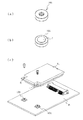
これらの固定具のうち、ネジ部材はバネ部材に比べて機械的強度が強いことから、持運びが自在で振動を多く受ける携帯用の電子機器内の基板を積層するのに多く使用されている。例えば、図9はネジ部材からなる公知の基板固定具を示したものであり、図9(a)は基板固定具の斜視図、図9(b)は図9(a)の基板固定具に吸着テープを取り付けた状態を示す斜視図、図9(c)は基板固定具が実装された親基板を示す外観斜視図、図10はネジ部材からなる他の公知の基板固定具を示したものであり、図10(a)は基板固定具の斜視図、図10(b)は図10(a)の基板固定具に吸着テープを取り付けた状態を示す斜視図、図10(c)は基板固定具が実装された親基板を示す外観斜視図である。 Among these fixtures, the screw member has a higher mechanical strength than the spring member, so it is often used to stack substrates in portable electronic devices that are portable and receive a lot of vibration. . For example, FIG. 9 shows a known substrate fixture made of a screw member. FIG. 9A is a perspective view of the substrate fixture, and FIG. 9B is a diagram of the substrate fixture of FIG. FIG. 9C is an external perspective view showing a parent board on which a board fixture is mounted, and FIG. 10 shows another known board fixture made of screw members. 10 (a) is a perspective view of the substrate fixture, FIG. 10 (b) is a perspective view showing a state where the suction tape is attached to the substrate fixture of FIG. 10 (a), and FIG. 10 (c) is the substrate. It is an external appearance perspective view which shows the parent board | substrate with which the fixing tool was mounted.
基板固定具10Aは、図9に示すように、所定の直径及び厚みを有し中央部に雌ネジが刻設された貫通孔を有する円盤状のナットからなる。また、基板固定具10Bは、図10に示すように、上下に所定の径を有する筒状突起が形成され、この筒状突起内に雌ネジが刻設された貫通孔が形成されたナットからなる。この基板固定具10Bは上方に向かって外径が異なる2段の筒状突起が塔状に形成されたピラミッド型をしている。これらの基板固定具10A、10Bは、大型サイズのマザーボード(以下、親基板という)P1上に小型サイズの子プリント配線基板(以下、子基板という)P2を積層するのに使用されている。すなわち、親基板P1は、比較的大判サイズの基板からなり、その表面に複数個の基板固定具10A又は10Bが固定される。また、子基板P2は、例えばPCIexpressと呼ばれるものであって、親基板P1より若干小型サイズの基板からなり、基板固定具10A、10Bの貫通孔に連通するネジ穴が形成されている。この子基板P2は、2枚の基板間に各種の半導体素子等が設けられた所定の機能を有するカード状のモジュール基板である。
As shown in FIG. 9, the board fixture 10 </ b> A is formed of a disk-shaped nut having a predetermined diameter and thickness and having a through hole in which a female screw is engraved at the center. Further, as shown in FIG. 10, the
親基板P1への基板固定具10Aの実装は、例えば2つの基板固定具10A、10Aを親基板P1上の取付け箇所にクリーム半田等を使用して仮止めし、その後、半田槽(リフロー槽)へ搬送して半田付けされる。この親基板P1への子基板P2の取付けは、子基板P2を各基板固定具10A、10A上に載置して、貫通孔Hにボルトを挿入して固定される。なお、他の基板固定具10Bの親基板P1への実装も同様の方法で行われる。
このような基板固定具10A、10Bは、別工程で作成されて、親基板P1へ実装されるが、この実装に際しては自動実装機構、例えばロボットアームによる自動実装が一般的に行われる。また、この基板固定具10A、10Bの実装に用いられるロボットアームは、基板固定具10A、10Bを吸引することで掴持し、親基板P1の実装位置まで持ち運びがなされるものが一般的に使用されている。しかしながら、基板固定具10A、10Bは、図9(a)及び図10(a)に示すように、それぞれの頂部に吸着面がないので、実装の際は通常、図9(b)及び図10(b)に示すように、各基板固定具10A、10Bの頂部に円形の吸着テープTを貼付して、この吸着テープTを吸着面に利用して、アームロボットで吸着し持ち運びを行って実装されている。この実装は、通常、以下の工程で行われている。
Such a
先ず、一方の面が吸着面となり、他方の面には保護シートが貼付された耐熱性を有する比較的長尺の吸着テープが準備される。この長尺な吸着テープと保護シートとの間には粘着層が形成され、保護シートは剥離自在となっている。そして、
(a)基板固定具10A、10Bの頂部の大きさに合わせて長尺な吸着テープをカットする吸着テープ定寸カット工程、
(b)カットされた吸着テープTから保護シートを剥がす保護シート剥がし工程、
(c)各基板固定具10A、10Bの頂部の面に吸着テープTを貼付する吸着テープ貼付工程、
(d)不図示のロボットアームで吸着テープの吸着面を吸着し、掴持する吸着工程、
(e)親基板P1の取付け箇所へ搬送し、実装する実装工程、
(f)親基板P1の表面或いは各基板固定具10A、10Bの底面にクリーム半田等を塗布し、このクリーム半田で基板固定具10A、10Bを親基板P1に仮止めし、各基板固定具10A、10Bが仮止めされた親基板P1を不図示のリフロー槽へ搬送して半田付けする半田付け工程、
(g)半田付けされた親基板P1から不要となった吸着テープTを各基板固定具10A、10Bの頂部から剥がし取る吸着テープ剥がし工程、
(h)剥がした吸着テープを廃棄物として処理する吸着テープ廃棄工程、
を順次行うことにより実装が行われる。そして、これらの工程のうち、(a)、(b)、(c)、(g)に示す各工程は、一部自動機を用いて行われることがあるものの、費用面からほとんどはそれぞれ人の手作業によって行われている。
First, a relatively long adsorbing tape having heat resistance with one surface serving as an adsorbing surface and a protective sheet attached to the other surface is prepared. An adhesive layer is formed between the long suction tape and the protective sheet, and the protective sheet can be peeled off. And
(A) a suction tape fixed-size cutting step for cutting a long suction tape according to the size of the top of the
(B) a protective sheet peeling step of peeling the protective sheet from the cut adhesive tape T;
(C) Adsorption tape application process of applying the adsorption tape T to the top surfaces of the
(D) A suction process for sucking and gripping the suction surface of the suction tape with a robot arm (not shown);
(E) a mounting process in which the substrate is transported to and mounted on the parent substrate P 1 ;
(F) Cream solder or the like is applied to the surface of the parent substrate P 1 or the bottom surfaces of the
(G) a suction tape peeling step of peeling off the unnecessary suction tape T from the soldered parent substrate P 1 from the top of each of the
(H) Adhesive tape disposal process for treating the peeled adhesive tape as waste,
Implementation is performed by sequentially performing the above. Of these processes, each of the processes shown in (a), (b), (c), and (g) may be performed by using some automatic machines, but most of them are human. Is done by hand.
このようにロボットアーム等を使用した自動実装は、それぞれのナット頂部に吸着面が無いため、頂部に吸着テープを貼付して、前記の工程、すなわち(a)吸着テープの定寸カット、(b)保護シート剥がし、(c)吸着テープ貼り付け、(d)吸着、(e)基板への実装、(f)半田付け、(g)吸着テープ剥がし、及び(h)吸着テープ廃棄、の各工程を経て基板へ実装されている。しかしながら、これらの工程のうち、(b)保護シート剥がし、及び(c)吸着テープ貼り付け工程はそれぞれ人の手作業で行わなければならないので作業性が悪く、また(c)吸着テープ貼り付け工程の際に位置ズレの恐れあり、このような位置ズレが発生すると後の(d)〜(f)工程において不都合が生じてしまう。 In this way, automatic mounting using a robot arm or the like has no suction surface at the top of each nut. Steps of peeling off the protective sheet, (c) adhering the adhering tape, (d) adsorbing, (e) mounting on the substrate, (f) soldering, (g) removing the adsorbing tape, and (h) discarding the adsorbing tape It is mounted on the board through. However, among these processes, (b) peeling of the protective sheet and (c) the adhering tape attaching process must be performed manually by humans, so the workability is poor, and (c) the adsorbing tape attaching process. In such a case, there is a risk of positional deviation. If such positional deviation occurs, inconveniences occur in the following steps (d) to (f).
また、(d)吸着、及び(e)基板への実装工程において、親基板P1に複数個基板固定具10A、10Bを取り付けなければいけない場合であっても1個ずつ吸着して実装しなければならないので作業効率が悪く、さらに、(f)半田付け工程では、吸着テープが高温(例えば240〜250℃)に晒されるので、溶融等して他に付着しないように耐熱性を有するものを使用しなければならず一般に高価となる。さらにまた、(g)吸着テープ剥がし工程は手作業によるので作業性が悪く、(h)吸着テープ廃棄工程では剥がした吸着テープTは廃棄するのみでリサイクルができない。したがって、この吸着テープTを貼付して実装する方法は、作業性および作業効率が悪く、実装コストが高くなる恐れがあり、また、使用後の吸着テープは廃棄処分となり省資源化ができない等の課題が潜在している。
Also, be implemented by adsorption (d) adsorption, and in (e) mounting step to the substrate, the main board P 1
本発明は、このような従来技術の課題を解決するためになされたもので、本発明の目的は、従来技術で必要とした吸着テープを用いることなく基板に基板固定具を実装可能な実装ホルダー及びこの実装ホルダーにより実装可能な基板固定具を提供することにある。 The present invention has been made to solve such problems of the prior art, and an object of the present invention is to provide a mounting holder capable of mounting a substrate fixture on a substrate without using the suction tape required in the prior art. Another object of the present invention is to provide a substrate fixture that can be mounted by the mounting holder.
また、本発明の他の目的は、上記の実装ホルダーを使用して基板へ基板固定具を実装できる基板固定具の実装方法を提供することにある。 Another object of the present invention is to provide a mounting method for a substrate fixture that can mount the substrate fixture on the substrate using the mounting holder.
上記目的を達成するために、請求項1に記載の実装ホルダーは、少なくともその上部に筒状突起を備える基板固定具をプリント基板上に実装機構により実装する際に用いられる耐熱性部材からなる実装ホルダーであって、
前記基板固定具を保持する1乃至複数の保持部と、前記実装機構へ吸着される吸着面を有する吸着部と、前記保持部と前記吸着部とを連結する1乃至複数本のアームと、からなり、前記保持部には前記基板固定具の筒状突起が圧入されて保持する装着穴が設けられていることを特徴とする。
In order to achieve the above object, the mounting holder according to
One or more holding parts for holding the substrate fixture, an adsorption part having an adsorption surface to be adsorbed to the mounting mechanism, and one or more arms for connecting the holding part and the adsorption part. Thus, the holding portion is provided with a mounting hole in which the cylindrical protrusion of the substrate fixture is press-fitted and held.
また、請求項2に記載の発明は、請求項1に記載の実装ホルダーにおいて、前記実装ホルダーは所定の肉厚を有する板状体から形成されていることを特徴とする。 According to a second aspect of the present invention, in the mounting holder according to the first aspect, the mounting holder is formed of a plate-like body having a predetermined thickness.
また、請求項3に記載の発明は、請求項2に記載の実装ホルダーにおいて、前記装着穴は前記保持部を上下に貫通した貫通穴で形成されていることを特徴とする。 According to a third aspect of the present invention, in the mounting holder according to the second aspect, the mounting hole is formed as a through hole that vertically penetrates the holding portion.
また、請求項4に記載の発明は、請求項1に記載の実装ホルダーにおいて、前記基板固定具の対向する側端には垂直に立設された一対の側壁が設けられており、前記保持部は前記一対の側壁間に挿入されたときに該一対の側壁の内壁面にその両側面が当接して該一対の側壁に挟持されることを特徴とする。 According to a fourth aspect of the present invention, in the mounting holder according to the first aspect of the present invention, a pair of side walls erected vertically are provided at opposing side ends of the substrate fixture, and the holding portion Is characterized in that when inserted between the pair of side walls, both side surfaces abut against the inner wall surfaces of the pair of side walls and are sandwiched between the pair of side walls.
また、請求項5に記載の発明は、請求項4に記載の実装ホルダーにおいて、前記基板固定具の一対の側壁の内壁面には係合溝が設けられており、前記保持部の両側面には、前記係合溝に係合する突起が設けられていることを特徴とする。 According to a fifth aspect of the present invention, in the mounting holder according to the fourth aspect, an engagement groove is provided on an inner wall surface of the pair of side walls of the substrate fixture, and both side surfaces of the holding portion are provided. Is provided with a protrusion for engaging with the engaging groove.
また、請求項6に記載の発明は、請求項1〜5の何れかに記載の実装ホルダーにおいて、前記アームは前記吸着部を中心にして複数本、所定長さ延設されており、該複数本のアームの少なくとも先端部には前記保持部が設けられていることを特徴とする。
The invention according to
請求項7に記載の基板固定具の発明は、第1基板上の所定位置に実装されて該第1基板に第2基板を固定する基板固定具であって、金属板材からなり、その上面には前記請求項1〜6の何れかに記載の実装ホルダーの保持部の装着穴に圧入される第1筒状突起を備え、該第1筒状突起には第1中空穴が設けられているとともに該第1中空穴の内壁面には取付けネジが刻設されていることを特徴とする。
The substrate fixing tool according to
また、請求項8に記載の発明は、請求項7に記載の基板固定具において、前記金属板材の対向する側端部には上面方向に立設した一対の側壁が設けられ、該一対の側壁間の長さは、前記実装ホルダーの保持部の両側面に当接する長さとなっていることを特徴とする。
The invention according to
また、請求項9に記載の発明は、請求項8に記載の基板固定具において、前記基板固定具は、前記一対の側壁が設けられた前記第1基板上に固定される下板部と、前記第1筒状突起が設けられた前記第2基板が固定される上板部と、前記下板部と上板部とを連結する結合部と、から形成され、前記上板部が前記結合部から前記下板部の前記一対の側壁間に位置するように2つ折りに折畳まれていることを特徴とする。
The invention according to
また、請求項10に記載の発明は、請求項8に記載の基板固定具において、前記一対の側壁は、その対向する側壁面に前記実装ホルダーの保持部に設けられた突起に係合される係合溝が形成されていることを特徴とする。 According to a tenth aspect of the present invention, in the substrate fixture according to the eighth aspect, the pair of side walls are engaged with protrusions provided on the holding portion of the mounting holder on the opposing side wall surfaces. An engagement groove is formed.
また、請求項11に記載の発明は、請求項7〜10の何れかに記載の基板固定具において、前記下板部には前記上板部の第1筒状突起の第1中空穴に対応する箇所に下方へ向けて第2中空穴を有する第2筒状突起が形成され、該第2中空穴の内壁面には前記第1中空穴に刻設された取付けネジに連通した取付けネジが刻設されていることを特徴とする。
The invention according to claim 11 is the substrate fixture according to any of
また、請求項12に記載の発明は、請求項11に記載の基板固定具において、前記第2筒状突起の外径は前記第1筒状突起の外径とは異なる外径を備えていることを特徴とする。 According to a twelfth aspect of the present invention, in the substrate fixture according to the eleventh aspect, the outer diameter of the second cylindrical protrusion is different from the outer diameter of the first cylindrical protrusion. It is characterized by that.
また、請求項13に記載の発明は、請求項11に記載の基板固定具において、前記第1及び第2筒状突起は、いずれもバーリング加工によって形成されていることを特徴とする。 The invention according to claim 13 is the substrate fixture according to claim 11, wherein each of the first and second cylindrical protrusions is formed by burring.
請求項14に記載の基板固定具の実装方法の発明は、前記請求項1〜6のいずれかに記載の実装ホルダーを用いて下記(1)〜(5)に示す工程を実行することにより、基板固定具を基板に実装することを特徴とする。
(1)前記実装ホルダーに前記基板固定具に組み付ける工程。
(2)実装機構により前記実装ホルダーの吸着部を吸着して該実装ホルダーを搬送し、前記基板へ実装する工程。
(3)前記実装ホルダーに装着された前記基板固定具を基板表面に仮止めする工程。
(4)仮止めされた前記基板固定具を前記実装ホルダーとともに半田槽へ搬送して半田付けする工程。
(5)半田付け終了後、前記実装ホルダーを前記基板から取外す前記実装ホルダー取外し工程。
Invention of the mounting method of the board | substrate fixture of Claim 14 performs the process shown to following (1)-(5) using the mounting holder in any one of the said Claims 1-6, A board fixture is mounted on the board.
(1) A process of assembling the mounting holder to the board fixture.
(2) A step of sucking the suction portion of the mounting holder by the mounting mechanism, transporting the mounting holder, and mounting on the substrate.
(3) A step of temporarily fixing the substrate fixture mounted on the mounting holder to the substrate surface.
(4) A step of transporting and soldering the temporarily fixed substrate fixture together with the mounting holder to a solder bath.
(5) The mounting holder removing step of removing the mounting holder from the substrate after completion of soldering.
本発明は、上記構成を備えることにより、以下に示す優れた効果を奏する。すなわち、請求項1の発明によれば、実装ホルダーに基板固定具を保持する保持部及び実装機構により吸着される吸着部を設け、この実装ホルダーを用いて基板固定具を基板に実装することにより、実装機構、例えばロボットアームで基板固定具を掴持するための吸着テープが不要となり、実装工程が簡略化できる。また保持部の装着穴に基板固定具の筒状突起を圧入して保持することにより、保持部の形成が容易になる。また、この実装ホルダーを耐熱性部材で形成したことにより、基板固定具の半田付けの際、一緒に半田槽に搬入することが可能となるとともに、半田付けの後回収すれば再利用が可能となるので省エネ効果が得られる。 By providing the above configuration, the present invention has the following excellent effects. That is, according to the first aspect of the present invention, the mounting holder is provided with the holding portion for holding the substrate fixture and the suction portion that is attracted by the mounting mechanism, and the substrate holder is mounted on the substrate using the mounting holder. In addition, a mounting mechanism, for example, a suction tape for gripping the substrate fixture by a robot arm is not required, and the mounting process can be simplified. Further, the cylindrical protrusion of the substrate fixture is press-fitted and held in the mounting hole of the holding part, thereby facilitating the formation of the holding part. In addition, by forming this mounting holder with a heat-resistant member, when soldering the board fixture, it can be carried into the solder bath together and can be reused if recovered after soldering Therefore, energy saving effect is obtained.
また、請求項2及び3の発明によれば、実装ホルダーを板状態とし、保持部に設けられる装着穴を貫通穴で形成したことで、装着穴の上下何れの方向からも基板固定具を圧入・保持させることができるので、実装ホルダーへ基板固定具を装着する作業性が向上する。 According to the second and third aspects of the invention, the mounting holder is in a plate state, and the mounting hole provided in the holding portion is formed as a through hole, so that the board fixture can be press-fitted in any direction above and below the mounting hole. -Since it can be held, the workability of mounting the substrate fixture on the mounting holder is improved.
また、請求項4の発明によれば、基板固定具に設けられた一対の側壁間に保持部が挟持されるようにしたので、基板固定具を実装ホルダーに取り付けた状態がより安定するとともに、基板固定具の位置決めが容易になる。
According to the invention of
また、請求項5の発明によれば、一対の側壁に係合溝が形成されている場合には、この係合溝に係合する突起を保持部の側面に形成することで、実装ホルダーに取り付けた基板固定具が更に安定する。
According to the invention of
また、請求項6の発明によれば、例えば吸着部から基板に実装したい数のアームを延設し、その先端部に保持部を設けることで、基板への基板固定具の実装が一度に実行できるので、実装時間が大幅に短縮できる。 According to the sixth aspect of the present invention, for example, the number of arms desired to be mounted on the substrate is extended from the suction portion, and the holding portion is provided at the distal end portion thereof, so that the substrate fixture can be mounted on the substrate at one time. As a result, implementation time can be greatly reduced.
また、請求項7の発明によれば、基板固定具に上述の実装ホルダーに保持可能なように第1筒状突起を設けることで、実装ホルダーに取り付けが可能となり、基板への実装が容易に行えるようになるとともに、粘着テープ等の部材が不要となり、省エネ効果が得られる。
According to the invention of
また、請求項8の発明によれば、一対の側壁が実装ホルダーの保持部の両側面に当接する距離に設けられていることで、実装ホルダーに基板固定具を取り付けたときにこの側壁が保持部を両側面から挟持するようになるので、基板固定具の実装ホルダーへの取り付け状態が安定する。
According to the invention of
また、請求項9の発明によれば、基板固定具を下板部と上板部で形成し、折畳むようにして形成されているので、プレス加工が容易な厚さの金属板材から形成したとしても、基板固定具の厚さを確保でき、強度に優れた基板固定具を提供することができるようになる。 According to the ninth aspect of the present invention, since the substrate fixture is formed by the lower plate portion and the upper plate portion and folded, even if formed from a metal plate material having a thickness that is easy to press. The thickness of the substrate fixture can be ensured, and a substrate fixture excellent in strength can be provided.
また、請求項10の発明によれば、側壁の内壁面に係合溝を設けることで、この係合溝を実装ホルダーの両側面に形成された突起に係合させることができるので、基板固定具の実装ホルダーへの固定がより安定する。 According to the invention of claim 10, by providing the engagement groove on the inner wall surface of the side wall, the engagement groove can be engaged with the protrusions formed on both side surfaces of the mounting holder. Fixation of the tool to the mounting holder is more stable.
また、請求項11の発明によれば、下板部に第1筒状突起の第1中空穴に連通する第2中空穴を有する第2筒状突起を形成することにより、第1基板の基板固定具実装位置にこの第2筒状突起が嵌合される窪み又は穴を形成すれば、第1基板への基板固定具の位置決めがより簡単に行えるようになる。また、第1中空穴と第2中空穴とに刻設された取り付けネジ(雌ネジ)が連続的に設けられていることで、ボルトによる両基板の固定時にボルトの螺合強度がより高くなる。 According to the invention of claim 11, the substrate of the first substrate is formed by forming the second cylindrical protrusion having the second hollow hole communicating with the first hollow hole of the first cylindrical protrusion in the lower plate portion. If a recess or a hole into which the second cylindrical protrusion is fitted is formed at the fixture mounting position, the substrate fixture can be positioned on the first substrate more easily. Further, since the mounting screws (female screws) engraved in the first hollow hole and the second hollow hole are continuously provided, the screwing strength of the bolts becomes higher when the two substrates are fixed with the bolts. .
また、請求項12の発明によれば、第2筒状突起と第1筒状突起の外径を異なるものとしたので、実装ホルダーへの取り付け方向を誤る恐れがなくなる。 According to the twelfth aspect of the present invention, since the outer diameters of the second cylindrical protrusion and the first cylindrical protrusion are different, there is no possibility that the mounting direction to the mounting holder is wrong.
また、請求項13の発明によれば、第1、第2筒状突起をプレス加工の一種であるバーリング加工で形成することができるので、旋盤加工などの比較的ロスの多い加工法に比べ、安価に、且つ簡単に形成することが可能となる。 Further, according to the invention of claim 13, since the first and second cylindrical protrusions can be formed by burring which is a kind of press working, compared with a relatively lossy machining method such as lathe machining, It can be formed inexpensively and easily.
請求項14の発明によれば、従来技術で述べた基板固定具実装工程に比べて格段に少ない工数で基板固定具の実装を行うことが可能となる。また、(5)に示す工程で取り外された実装ホルダーは再度の使用が可能であり、従来のようにその都度粘着テープを破棄するような無駄がなく、省エネ効果が得られる。 According to the invention of claim 14, it is possible to mount the substrate fixture with much fewer man-hours than the substrate fixture mounting step described in the prior art. Further, the mounting holder removed in the step shown in (5) can be used again, and there is no waste of discarding the adhesive tape each time as in the prior art, and an energy saving effect is obtained.
以下、図面を参照して本発明の最良の実施形態を説明する。但し、以下に示す実施形態は、本発明の技術思想を具体化するための実装ホルダー、基板固定具及び基板固定具の実装方法を例示するものであって、本発明をこれらに特定することを意図するものではなく、特許請求の範囲に含まれるその他の実施形態のものも等しく適応し得るものである。 Hereinafter, the best embodiment of the present invention will be described with reference to the drawings. However, the embodiment described below exemplifies a mounting holder, a substrate fixture, and a method for mounting the substrate fixture for embodying the technical idea of the present invention, and the present invention is specified to these. It is not intended and other embodiments within the scope of the claims are equally applicable.
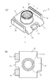
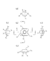
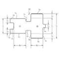
図1は本発明の実施例1に係る基板固定具を示したもので、図1(a)は基板固定具の外観斜視図、図1(b)は図1(a)のX方向からみた背面図、図2は図1の基板固定具を所定の角度からみたもので、図2(a)は平面図、図2(b)及び図2(c)は左右の側面図、図2(d)及び図2(e)は上下の側面図、図3は図1の基板固定具の断面図を示すものであり、図3(a)は図2(a)のA−A線の断面図、図3(b)は図2(a)のB−B線の断面図、図3(c)は図2(a)のC−C線の断面図である。 1A and 1B show a substrate fixture according to a first embodiment of the present invention. FIG. 1A is an external perspective view of the substrate fixture, and FIG. 1B is a view from the X direction of FIG. FIG. 2 is a rear view, and FIG. 2 is a plan view of the substrate fixture of FIG. 1, FIG. 2 (a) is a plan view, FIGS. 2 (b) and 2 (c) are left and right side views, FIG. d) and FIG. 2 (e) are upper and lower side views, FIG. 3 is a sectional view of the substrate fixture of FIG. 1, and FIG. 3 (a) is a sectional view taken along line AA of FIG. 2 (a). FIG. 3B is a sectional view taken along line BB in FIG. 2A, and FIG. 3C is a sectional view taken along line CC in FIG.
実施例1に係る基板固定具1は、図1〜図3に示すように、両側端部をそれぞれ折曲起立させて対向する一対の側壁2BR、2BLを設けた下板部2Bと、この下板部2Bに結合部2Cで連結された上板部2Aとを有し、上板部2Aは結合部2Cで折り返されることにより両側壁2BR、2BL間に積層されている。上板部2Aには、その表面から第1中空穴31を有する第1筒状突起3Aが突出され、この第1筒状突起3Aの第1中空穴内31の内壁面には雌ネジ4Aが刻設されている。また、第1筒状突起3Aの外径は子基板(第2基板)P2に設けられた貫通孔の内径とほぼ同一であり、両基板P1、P2の取付けの際には第1筒状突起3Aの先端部は子基板P2の貫通孔内に入り込むようになっている。加えて、下板部2Bの両側壁2BR、2BLの高さは、この側壁2BR、2BLの頂壁で子基板P2を支持するので両基板P1、P2の基板間距離と等しいことになる。よってこの高さは使用する子基板P2、または両基板P1、P2の基板間距離に合わせて適宜設定するとよい。ただし、第1筒状突起3Aを子基板P2の貫通孔内に挿入できるように、第1筒状突起3Aよりも背低にすると子基板P2の位置決めが容易にできるので好ましい。また、上板部2Aは、その先端の一部が下方へ折曲されて、半田付け足部となる小突出部2AR、2ALが形成されている。下板部2Bからも各小突出部2AR、2ALの間から、下板部の小突出部2BCが突出されている。これらの小突出部2AR、2AL及び2BCはクリーム半田による親基板(第1基板)P1への位置決め固定をより容易にするために設けられたものである。また、この基板固定具1が結合部2Cで2つ折りにされて形成されているので、例えば横方向から外力が生じた際に上板部2Aと下板部2Bとが離反することがある。しかし、小突出部2AR、2ALにより上板部2Aが結合部2Cと対向する位置で親基板P1に半田付けされるので、外力による上板部2Aと下板部2Bとの離反を防止することができる。
As shown in FIGS. 1 to 3, the
また、下板部2Bは、下板部2Bと上板部2Aとが結合部2Cで折り曲げられた状態において、上板部2Aの第1筒状突起3Aの第1中空穴31に対応する箇所に、下方へ向けてこの第1中空穴31に連通した第2中空穴32を有する第2筒状突起3Bが形成され、この第2中空穴32の内壁面に雌ネジ4Bが刻設されている。なお、第1、第2筒状突起3A、3Bは、その外径が異なっているが、その点については後述する。そして、この下板部2Bの対向するそれぞれの側壁2BR、2BLは、その対向する側壁面に係止部2B0、2B0が形成されている。これらの係止部2B0、2B0は係止溝で形成されており、これらの係止溝は後述する実装ホルダー5に係合される。
Further, the
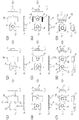
この基板固定具1は、図4に示すプロセスで作成される。なお、図4は図1の基板固定具のプレス加工のプロセスを示し、図4(1)〜図4(9)の各図(a1)〜(a9)は各プロセスにおける平面図、各図(b1)〜(b9)は図4(1)の(a1)に示したZ1方向からみた側面図、各図(c1)〜(c9)は図4(1)の(a1)に示したZ2方向からみた側面図、図5は図4(1)の素材板を拡大した平面図である。基板固定具1は、不図示の比較的大判の平板の金属板から所定形状の素材板を打ち抜き、この素材板2Xをプレス加工して作成されるので、先ず、この素材板2Xの形状を図5を参照して説明する。
This
打ち抜かれる素材板2Xは、図5に示すように、矩形状の下板部2Bと、この下板部2Bの上面に折畳み積層される上板部2Aと、これらの下板部2Bと上板部2Aとを連結する結合部2Cとを有している。下板部2Bは、比較的長い長さL1の対向する一対の長尺辺2B1、2B2及び幅長W1の短辺2B3、2B4を有し、外側の長尺辺2B1の略中央部には外側へ突出した小突出部2BCが設けられ、他の長尺辺2B2の中央部には結合部2Cが連結されている。この小突出部2BCの長さはL4となっている。この下板部2Bの両側は、端部から距離L2だけ離れた箇所から折り曲げられて一対の対向する側壁2BL、2BRが形成される。
As shown in FIG. 5, the
上板部2Aは、長さL3より若干短い長さL5の対向する一対の短辺2A1、2A2及び幅長W2(W2=W1)の対向する一対の短辺2A3、2A4を有し、外側の短辺2A2には、その両端に外側へ略同じ長さL6で突出した小突出部2AL、2ARが設けられている。一方の短辺2A1の中央部は結合部2Cに結合されている。長さL4、L6の関係は、上板部2Aが折畳まれたときに、小突出部2A1、2A2間に小突出部2BCが重なることなく位置する長さになっている。
このような形状に打ち抜かれた素材板2Xは、図4に示すプロセスでプレス加工される。素材板2Xは、先ず、上板部2Aの中央部に、表面から裏面に向けて所定径の第1中空穴31を有する第1筒状突起3Aが形成される(図4(1)、図4(2)参照)。この第1筒状突起3Aの外径は、後述する実装ホルダー5の装着穴7に圧入される長さになっている。また、この第1筒状突起3Aはプレス加工の一種であるバーリング(burring)加工により形成される。そして、この第1中空穴31の内壁面に雌ネジ4Aが刻設される(図4(3)参照)。
The
次いで、下板部2Bの中央部に、表面から裏面に向けて所定径の第2中空穴32を有する第2筒状突起3Bが形成される(図4(4)参照)。第2筒状突起3Bの外径は、基板固定具1の上下を誤って反対にすることを防止するため、第1筒状突起3Aの外径とは異なる径に形成されると好ましい。この第2筒状突起3Bもバーリング(burring)加工により形成される。その後、この第2中空穴32の内壁面に雌ネジ4Bが刻設される(図4(5)参照)。この雌ネジ4Bは、雌ネジ4Aに対して連続的に刻設される。
Then, the central portion of the
さらに、下板部2Bの両側部分に係止溝2B0、2B0を形成し(図4(6)参照)、この両側部分を折り曲げて対向する一対の側壁2BL、2BRが形成される(図4(7)参照)。この折り曲げにより、両側壁2BL、2BRは弾性片となり、この側壁2BL、2BR間に後述する実装ホルダー5が挿入されたとき、この弾性片が実装ホルダー5を挟持する。その後、上板部2Aの小突出部2AR、2ALが上方へ折り曲げられる(図4(8)参照)。最後に、下板部2Bの一対の側壁2BL、2BR間に上板部2Aを積層するように、結合部2Cで2つに折り曲げる。なお、下板部2Bの側壁2BL、2BRがこの折り曲げの際の位置決め機能をも備えているので、簡単に正確な折り曲げ加工を行うことができる。以上の工程により、基板固定具1が完成する(図4(9)参照)。
Further, locking
このようにして形成された基板固定具1は、下板部2Bの両側部に一対の側壁2BL、2BRが設けられ、これらが弾性力を有することになるので、これらの側壁を利用して実装ホルダー5に挟持・保持させることができる。したがって、実装ホルダー5への保持が簡単になり、従来技術で必要としていた吸着テープTの貼付が不要となる。
The thus formed
さらに、第1、第2筒状突起3A、3Bは、一方の外径を他のそれと異ならせ、後述する実装ホルダーの保持部を第1筒状突起3Aの外径に合わせることにより、基板固定具1が上下逆に保持されることがなくなる。また、下板部2Bに第2筒状突起3Bを設けることにより、この第2筒状突起3Bを利用して親基板P1への位置決め固定が簡単になる。さらにまた、第1、第2中空穴31、32を連通させて、両中空穴31、32の内壁に取付け用の雌ネジを刻設することにより、従来技術の図9(c)及び図10(c)に示すものと同様に、第1筒状突起3Aを子基板P2の貫通孔Hに挿入した状態でこの中空穴31、32にボルトを締結すれば親子基板P1、P2の固定がより堅固に行えるようになる。
Further, the first and second
さらにまた、この基板固定具1は、所定の形状に打ち抜いた素材板をプレス加工(詳しくはバーリング加工)することにより形成されるので、材料費が安くかつ加工が簡単になり安価に作製できる。
Furthermore, since the
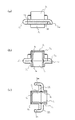
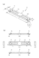
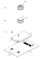
次に、本発明の実施例1に係る実装ホルダー5を図6を参照して説明する。なお、以下に示す実装ホルダー5は、基板上に設けられた基板固定具1の実装位置が2箇所所定距離離れた位置に設けられている親基板P1に対して基板固定具1を実装するのに適したものである。図6は実装ホルダーを示したものであり、図6(a)は外観斜視図、図6(b)の(1)は平面図、図6(b)の(2)及び(3)は左右の側面図、図6(b)の(4)及び(5)は上下の側面図である。
Next, the mounting
この実装ホルダー5は、図6に示すように、所定の厚さD、幅長W及び長さLを有する細長の板状体からなり、長手方向の両端部に基板固定具1を保持する保持部6、6が設けられ、中央部に不図示のロボットアームに吸着される吸着部9が設けられ、吸着部9と保持部6、6との間がアーム6A、6Aで連結されている。耐熱性の合成樹脂材で形成されている。このうち、吸着部9はその表裏面が平坦面となっており、この中央部のみ円形になるよう、その幅が一部拡径されている。そして、この吸着部9の表裏面は、ロボットアームにより吸着・保持される際に隙間が形成されないように所定の加工がなされていると好ましい。
As shown in FIG. 6, the mounting
一対の保持部6、6の間隔は、親基板P1上に2つ設けられている基板固定具1の実装位置間の長さに対応する長さとなっている。また、その幅長Wは基板固定具1の一対の対向する側壁2BR、2BL間に弾性圧接する長さに設定されている。さらに、その厚さDは各側壁2BR、2BLの高さより若干長くなっている。このような構成を備える一対の保持部6、6は、それぞれ同じ構造を有しており、図6(a)に示すように、その中央部には基板固定具1の第1筒状突起3Aが挿入される装着穴7が設けられ、その両側面には基板固定具1の両側壁2BL、2BRに設けられた係止溝2B0、2B0に係合される一対の線状突起8A、8Bが設けられている。
The distance between the pair of holding
装着穴7は、第1筒状突起3Aの外径より僅かに大きな直径を有し、板状体からなる実装ホルダー5の表面から裏面へ貫通している。また、この装着穴7の内壁面には、図6(b)に示すように、中心に向けて突出した複数本(なお、図6(b)では等間隔で3本)の係止突起71〜73が形成されている。これらの係止突起71〜73は、装着穴7に基板固定具1の第1筒状突起3Aが圧入されたときに、この第1筒状突起3Aの外周壁面に当接されて基板固定具1を保持するとともに、位置決め機能も果たすものである。このように装着穴7を貫通穴にすると、実装ホルダー5の上下何れの面からも基板固定具1を圧入固定することができるので、基板固定具1の取り付けが簡単になる。また、保持部6の両側壁面には、線状突起8A、8Bが実装ホルダー5の表裏いずれの方向から圧入された場合においても基板固定具1の係止溝2B0、2B0に係合するように多段的に、つまりは上下にずらした位置に設けられている。これらの線状突起8A、8Bを2段にすることにより、基板固定具1が実装ホルダー5の表裏のどちらから圧入されても、確実に係止溝2B0、2B0と線状突起8A、8Bとを係合させることが可能になる。
Mounting
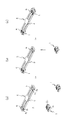
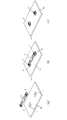
この実装ホルダー5を用いた基板固定具1の親基板P1への実装は、以下の工程で行われる。なお、図7は実装ホルダーへの基板固定具の組み付け工程を示した斜視図、図8は基板固定具が組み付けられた実装ホルダーにより基板へ実装する実装工程を示した斜視図である。
Implementation of the main board P 1 substrate fixture 1 using the mounting
(a)基板固定具の組み付け工程
この工程では、図7(a)〜図7(c)に示すように、基板固定具1の両側壁2BL、2BR間に実装ホルダー5の両側面を当接させて押し込み、同時に第1筒状突起3Aを保持部6の装着穴7に圧入して実装ホルダー5に基板固定具1を保持させる。この際、両側壁2BL、2BRは弾性力を有するので、実装ホルダー5の両側面に設けられた線状突起8A、8Bを弾性変形しながら乗り越えこの線状突起8A、8Bが係止溝2B0、2B0に係合し、基板固定具1の両側壁2BL、2BRによって実装ホルダー5を挟持した状態になる。このように線状突起8A、8Bと係止溝2B0、2B0とが係合するので基板固定具1が実装途中で脱落することがない。このとき、係止溝2B0、2B0が実装ホルダー5のいずれか一方の線状突起8A、8Bに係合されて確実に保持されるので、実装ホルダー5は天地を逆にしても同様に基板固定具1を装着でき、表裏面を確かめることなく作業ができるので作業性がよく作業効率が向上する。さらにまた、この状態においては基板固定具1の第1筒状突起3Aの外周壁面が装着穴7内の係止突起71〜73に当接されているので、基板固定具1が正確に位置決めされた状態で圧接保持される。
(A) Assembling process of board fixing tool In this process, as shown in FIGS. 7 (a) to 7 (c), both side surfaces of the mounting
(b)吸着工程
この工程では、不図示のロボットアームで実装ホルダー5の吸着部9に吸着させて、親基板P1へ搬送される(図7(c)参照)。
(B) an adsorption step in this process, is adsorbed to the
(c)実装工程
この工程では、親基板P1の実装位置a、bには予めクリーム半田等を塗布しておき、この実装位置a、bへ実装ホルダー5に保持された基板固定具1を載置することで仮止めを行う。なお、親基板P1の実装位置には基板固定部の第2筒状突起3Bが嵌合される窪み又は穴が形成されており、第2筒状突起3Bはこの窪み又は穴に嵌合されて位置決めがなされる。
(C) mounting step In this step, the mounting position a parent substrate P 1, b leave applied in advance cream solder or the like, this mounting position a, the
(d)半田付け工程
次いで、実装ホルダー5とともに親基板P1へ実装された基板固定具1を半田槽へ送り、高温でリフローすることで親基板P1と基板固定具1を半田付けする。なお、基板固定具1を保持している実装ホルダー5は耐熱性を備えているので、半田槽内で溶解することはない。
(D) Soldering Step Next, the
(e)ホルダー取外し工程
半田槽から搬出された親基板P1を冷却して半田付けがなされると、親基板P1から実装ホルダー5を取外す。この取外しは、実装ホルダー5は基板固定具1に圧接保持されているだけなので上方へ引っ張ることにより簡単に取り外せる。
(E) When soldering the main board P 1 taken out from the holder removal step solder bath and cooling is made, remove the mounting
この実装方法によれば、実装ホルダー5を用いることにより、工程が簡略化され、各工程でも作業性が向上する。よって、実装コストの低減、省資源化が可能である。例えば、従来技術で必要としていた吸着テープが不要になる。また、一度に複数個の基板固定具を実装できるので、実装の作業性及び作業効率が大幅に向上する。さらに、実装ホルダーの再使用が可能になり資源の無駄がなくなる。
According to this mounting method, the use of the mounting
本発明を前記の実施形態のものに限定されるものでなく、種々変更してもよい。例えば、実施形態では、上下板部2A、2Bにそれぞれ第1、第2筒状突起3A、3Bを設けたが、下板部2Bの第2筒状突起3Aを省いてもよい。また、実装ホルダー5は、長尺板状体の両端に保持部6、6を設けたが、それらの間に更なる保持部を設けてもよく、または、吸着部9を中心にして、この吸着部9から放射状に複数本のアーム6Aを突出させて各アーム6Aの先端にそれぞれ保持部6を設けるようにしてもよい。この構成により、複数個の実装位置が設けられた親基板P1であっても複数の基板固定具1を一度に実装することが可能になる。
The present invention is not limited to the embodiment described above, and various modifications may be made. For example, in the embodiment, the upper and
1 基板固定具
2A 上板部
2B 下板部
2C 結合部
2BR、2BL 側壁
2B0 係止部(係止溝)
3A 第1筒状突起
31 第1中空穴
3B 第2筒状突起
32 第2中空穴
4A 第1取付けネジ(雌ネジ)
4B 第2取付けネジ(雌ネジ)
5 実装ホルダー
6 保持部
6A アーム
7 装着穴
71〜73 係止突起
8A、8B 線状突起
9 吸着部
DESCRIPTION OF
3 A 1st
4 B Second mounting screw (female screw)
5 mounting
Claims (14)
前記基板固定具を保持する1乃至複数の保持部と、前記実装機構へ吸着される吸着面を有する吸着部と、前記保持部と前記吸着部とを連結する1乃至複数本のアームと、からなり、前記保持部には前記基板固定具の筒状突起が圧入されて保持する装着穴が設けられていることを特徴とする実装ホルダー。 A mounting holder made of a heat-resistant member used when mounting a board fixture having a cylindrical protrusion on at least an upper part thereof on a printed board by a mounting mechanism,
One or more holding parts for holding the substrate fixture, an adsorption part having an adsorption surface to be adsorbed to the mounting mechanism, and one or more arms for connecting the holding part and the adsorption part. The mounting holder is provided with a mounting hole in which the cylindrical projection of the substrate fixture is press-fitted and held.
(1)前記実装ホルダーに前記基板固定具に組み付ける工程。
(2)実装機構により前記実装ホルダーの吸着部を吸着して該実装ホルダーを搬送し、前記基板へ実装する工程。
(3)前記実装ホルダーに装着された前記基板固定具を基板表面に仮止めする工程。
(4)仮止めされた前記基板固定具を前記実装ホルダーとともに半田槽へ搬送して半田付けする工程。
(5)半田付け終了後、前記実装ホルダーを前記基板から取外す前記実装ホルダー取外し工程。 The board fixture is mounted on a board by performing the steps shown in the following (1) to (5) using the mounting holder according to any one of claims 1 to 6. How to implement
(1) A process of assembling the mounting holder to the board fixture.
(2) A step of sucking the suction portion of the mounting holder by the mounting mechanism, transporting the mounting holder, and mounting on the substrate.
(3) A step of temporarily fixing the substrate fixture mounted on the mounting holder to the substrate surface.
(4) A step of transporting and soldering the temporarily fixed substrate fixture together with the mounting holder to a solder bath.
(5) The mounting holder removing step of removing the mounting holder from the substrate after completion of soldering.
Priority Applications (1)
| Application Number | Priority Date | Filing Date | Title |
|---|---|---|---|
| JP2006350757A JP2008166317A (en) | 2006-12-27 | 2006-12-27 | Mounting holder, board fixture, and board fixture mounting method |
Applications Claiming Priority (1)
| Application Number | Priority Date | Filing Date | Title |
|---|---|---|---|
| JP2006350757A JP2008166317A (en) | 2006-12-27 | 2006-12-27 | Mounting holder, board fixture, and board fixture mounting method |
Publications (1)
| Publication Number | Publication Date |
|---|---|
| JP2008166317A true JP2008166317A (en) | 2008-07-17 |
Family
ID=39695454
Family Applications (1)
| Application Number | Title | Priority Date | Filing Date |
|---|---|---|---|
| JP2006350757A Pending JP2008166317A (en) | 2006-12-27 | 2006-12-27 | Mounting holder, board fixture, and board fixture mounting method |
Country Status (1)
| Country | Link |
|---|---|
| JP (1) | JP2008166317A (en) |
Citations (7)
| Publication number | Priority date | Publication date | Assignee | Title |
|---|---|---|---|---|
| JPS5937415A (en) * | 1982-08-26 | 1984-02-29 | Mitsubishi Electric Corp | Analyzer for sideslipping speed of ship |
| JPS5978656A (en) * | 1982-10-26 | 1984-05-07 | Nippon Sanso Kk | Method for treating rice |
| JPH0393040U (en) * | 1990-01-16 | 1991-09-24 | ||
| JPH09214151A (en) * | 1996-01-31 | 1997-08-15 | Matsukueito:Kk | Fixture for printed wiring board |
| JP2002217569A (en) * | 2001-01-18 | 2002-08-02 | Matsushita Electric Ind Co Ltd | Circuit board fixture and electronic equipment provided with the fixture |
| JP2003123871A (en) * | 2001-10-05 | 2003-04-25 | Mac Eight Co Ltd | Mounting device for printed circuit board |
| JP2004327646A (en) * | 2003-04-24 | 2004-11-18 | D D K Ltd | Fixing member and its fixing method |
-
2006
- 2006-12-27 JP JP2006350757A patent/JP2008166317A/en active Pending
Patent Citations (7)
| Publication number | Priority date | Publication date | Assignee | Title |
|---|---|---|---|---|
| JPS5937415A (en) * | 1982-08-26 | 1984-02-29 | Mitsubishi Electric Corp | Analyzer for sideslipping speed of ship |
| JPS5978656A (en) * | 1982-10-26 | 1984-05-07 | Nippon Sanso Kk | Method for treating rice |
| JPH0393040U (en) * | 1990-01-16 | 1991-09-24 | ||
| JPH09214151A (en) * | 1996-01-31 | 1997-08-15 | Matsukueito:Kk | Fixture for printed wiring board |
| JP2002217569A (en) * | 2001-01-18 | 2002-08-02 | Matsushita Electric Ind Co Ltd | Circuit board fixture and electronic equipment provided with the fixture |
| JP2003123871A (en) * | 2001-10-05 | 2003-04-25 | Mac Eight Co Ltd | Mounting device for printed circuit board |
| JP2004327646A (en) * | 2003-04-24 | 2004-11-18 | D D K Ltd | Fixing member and its fixing method |
Similar Documents
| Publication | Publication Date | Title |
|---|---|---|
| US5742484A (en) | Flexible connector for circuit boards | |
| KR101402925B1 (en) | Vaccum Zig System For Flexible Printed Circuit Board | |
| JP5576429B2 (en) | Connection method to printed circuit without using soldering of electric drive unit | |
| JPH10209594A (en) | Connection structure of flexible printed circuit board and rigid printed circuit board | |
| JP2008166317A (en) | Mounting holder, board fixture, and board fixture mounting method | |
| JP4952869B1 (en) | Solder piece, chip solder, and method of manufacturing solder piece | |
| JP4805683B2 (en) | Fixing member and fixing structure | |
| JP4111796B2 (en) | Press-fit terminal press-fitting method | |
| JP2013161541A (en) | Connection terminal | |
| JPH0317240B2 (en) | ||
| JP2008192805A (en) | Board fixture | |
| JP2004228276A (en) | Method of connecting connector to substrate | |
| CN110480117A (en) | Tool for stitching and reflow soldering tool component for circuit board solder reflow | |
| CN110480118A (en) | Tool for stitching and reflow soldering tool component for circuit board solder reflow | |
| JP4384316B2 (en) | Electronic component module | |
| CN115134998A (en) | PCB and manufacturing method thereof | |
| JP2001313496A (en) | Method and device for mounting hybrid integrated circuit in electronic circuit unit | |
| JP5601828B2 (en) | Printed wiring board laminate and manufacturing method thereof | |
| JPH1174631A (en) | Electronic circuit board | |
| JP2003187890A (en) | Electrical connection terminal | |
| JP4600141B2 (en) | Method for manufacturing FPC with connector | |
| JP2008021911A (en) | Board jig for substrate dividing apparatus and substrate dividing apparatus provided with the same | |
| JP2003123871A (en) | Mounting device for printed circuit board | |
| JP2011204960A (en) | Electronic apparatus | |
| JP2008171631A (en) | Connection terminal |
Legal Events
| Date | Code | Title | Description |
|---|---|---|---|
| A621 | Written request for application examination |
Free format text: JAPANESE INTERMEDIATE CODE: A621 Effective date: 20091113 |
|
| A977 | Report on retrieval |
Free format text: JAPANESE INTERMEDIATE CODE: A971007 Effective date: 20110722 |
|
| A131 | Notification of reasons for refusal |
Free format text: JAPANESE INTERMEDIATE CODE: A131 Effective date: 20110726 |
|
| A02 | Decision of refusal |
Free format text: JAPANESE INTERMEDIATE CODE: A02 Effective date: 20111124 |