JP2008137559A - On-vehicle electronic system, on-vehicle electronic apparatus, and power supply control method of portable electronic apparatus - Google Patents
On-vehicle electronic system, on-vehicle electronic apparatus, and power supply control method of portable electronic apparatus Download PDFInfo
- Publication number
- JP2008137559A JP2008137559A JP2006327663A JP2006327663A JP2008137559A JP 2008137559 A JP2008137559 A JP 2008137559A JP 2006327663 A JP2006327663 A JP 2006327663A JP 2006327663 A JP2006327663 A JP 2006327663A JP 2008137559 A JP2008137559 A JP 2008137559A
- Authority
- JP
- Japan
- Prior art keywords
- electronic device
- vehicle
- portable electronic
- audio
- power
- Prior art date
- Legal status (The legal status is an assumption and is not a legal conclusion. Google has not performed a legal analysis and makes no representation as to the accuracy of the status listed.)
- Pending
Links
Images


Classifications
-
- B—PERFORMING OPERATIONS; TRANSPORTING
- B60—VEHICLES IN GENERAL
- B60R—VEHICLES, VEHICLE FITTINGS, OR VEHICLE PARTS, NOT OTHERWISE PROVIDED FOR
- B60R11/00—Arrangements for holding or mounting articles, not otherwise provided for
- B60R11/02—Arrangements for holding or mounting articles, not otherwise provided for for radio sets, television sets, telephones, or the like; Arrangement of controls thereof
-
- H—ELECTRICITY
- H02—GENERATION; CONVERSION OR DISTRIBUTION OF ELECTRIC POWER
- H02J—CIRCUIT ARRANGEMENTS OR SYSTEMS FOR SUPPLYING OR DISTRIBUTING ELECTRIC POWER; SYSTEMS FOR STORING ELECTRIC ENERGY
- H02J7/00—Circuit arrangements for charging or depolarising batteries or for supplying loads from batteries
- H02J7/0068—Battery or charger load switching, e.g. concurrent charging and load supply
-
- B—PERFORMING OPERATIONS; TRANSPORTING
- B60—VEHICLES IN GENERAL
- B60R—VEHICLES, VEHICLE FITTINGS, OR VEHICLE PARTS, NOT OTHERWISE PROVIDED FOR
- B60R16/00—Electric or fluid circuits specially adapted for vehicles and not otherwise provided for; Arrangement of elements of electric or fluid circuits specially adapted for vehicles and not otherwise provided for
- B60R16/02—Electric or fluid circuits specially adapted for vehicles and not otherwise provided for; Arrangement of elements of electric or fluid circuits specially adapted for vehicles and not otherwise provided for electric constitutive elements
- B60R16/03—Electric or fluid circuits specially adapted for vehicles and not otherwise provided for; Arrangement of elements of electric or fluid circuits specially adapted for vehicles and not otherwise provided for electric constitutive elements for supply of electrical power to vehicle subsystems or for
-
- B—PERFORMING OPERATIONS; TRANSPORTING
- B60—VEHICLES IN GENERAL
- B60R—VEHICLES, VEHICLE FITTINGS, OR VEHICLE PARTS, NOT OTHERWISE PROVIDED FOR
- B60R11/00—Arrangements for holding or mounting articles, not otherwise provided for
- B60R2011/0042—Arrangements for holding or mounting articles, not otherwise provided for characterised by mounting means
- B60R2011/0049—Arrangements for holding or mounting articles, not otherwise provided for characterised by mounting means for non integrated articles
- B60R2011/0064—Connection with the article
- B60R2011/0075—Connection with the article using a containment or docking space
-
- H—ELECTRICITY
- H02—GENERATION; CONVERSION OR DISTRIBUTION OF ELECTRIC POWER
- H02J—CIRCUIT ARRANGEMENTS OR SYSTEMS FOR SUPPLYING OR DISTRIBUTING ELECTRIC POWER; SYSTEMS FOR STORING ELECTRIC ENERGY
- H02J2310/00—The network for supplying or distributing electric power characterised by its spatial reach or by the load
- H02J2310/40—The network being an on-board power network, i.e. within a vehicle
- H02J2310/46—The network being an on-board power network, i.e. within a vehicle for ICE-powered road vehicles
Abstract
Description
本発明は、携帯電子装置が車載電子装置に対して着脱可能な車載用電子システムに関する。 The present invention relates to an in-vehicle electronic system in which a portable electronic device is detachable from an in-vehicle electronic device.
従来、携帯電子装置、例えばナビゲーション装置は、パーソナルナビゲーションデバイス(以下、PNDと表記する)と呼ばれる、簡易的ではあるが可搬性を持った小型のナビゲーション装置と、車両のダッシュボードに形成された凹部(DIN開口)内に収容されて固定される車載用のナビゲーション装置とが広く一般的に知られている。車載用のナビゲーション装置は、車両からの車速等の情報により高精度な案内が可能であり、さらにはオーディオ装置を備えたものも提案されている。 2. Description of the Related Art Conventionally, a portable electronic device, for example, a navigation device, is called a personal navigation device (hereinafter referred to as PND), a simple but portable small navigation device, and a recess formed in a dashboard of a vehicle. A vehicle-mounted navigation device that is housed and fixed in a (DIN opening) is widely known. A vehicle-mounted navigation device can provide highly accurate guidance based on information such as a vehicle speed from a vehicle, and a device equipped with an audio device has also been proposed.
近年、PND型ナビゲーション装置の可搬性と、車載用ナビゲーション装置の高精度な案内性能とを兼ね備えたオーディオ・ナビゲーションシステムが提案されている。このオーディオ・ナビゲーションシステムは、オーディオ部とナビ部とを備え、装置本体は、車両のDIN開口部に収容、固定されているが、ナビ部はオーディオ部から取り外すことができる。取り外されたナビ部は、電源を単独で備え、取り外した状態でナビゲーションが可能に構成されている。
そのため、取り外し可能なナビ部を備えたオーディオ・ナビゲーションシステムにおいて、ユーザの使い勝手をいかに向上させるかが課題となっている。
In recent years, an audio navigation system that combines the portability of a PND type navigation device and the highly accurate guidance performance of an in-vehicle navigation device has been proposed. This audio navigation system includes an audio unit and a navigation unit, and the apparatus main body is housed and fixed in a DIN opening of the vehicle, but the navigation unit can be removed from the audio unit. The removed navigation unit has a power source alone and is configured such that navigation is possible in the removed state.
Therefore, how to improve the usability of the user is an issue in an audio navigation system having a removable navigation unit.
特許文献1は、カーオーディオのパネルがカーオーディオの本体から取り外されたことを検出すると、カーオーディオ本体の電源をオフする技術を開示している。 Patent Document 1 discloses a technique for turning off the power of the car audio body when it is detected that the car audio panel is detached from the car audio body.
特許文献2に開示のナビゲーション装置は、車両に固定的に搭載されるメインナビゲーション装置と、車両に着脱可能に装着されたサブナビゲーション装置とを有しており、サブナビゲーション装置は、操作スイッチの操作によってオン状態となり、ナビゲーションを行う。 The navigation device disclosed in Patent Document 2 includes a main navigation device that is fixedly mounted on a vehicle, and a sub-navigation device that is detachably mounted on the vehicle. The sub-navigation device operates an operation switch. To turn on and perform navigation.
しかしながら、特許文献1の開示技術は、パネルがカーオーディオ本体から取り外されると、カーオーディオ本体の電源消し忘れを防止するためにカーオーディオ本体の電源をオフするものであって、本体から取り外された装置側の電源オンとオフとの切り替えをどのようなタイミングで行えば、ユーザの使い勝手を向上させることができるかといった技術課題には着目していない。
特許文献2も、操作スイッチの操作によってサブナビゲーション装置の電源オン、オフを切り替えるものであって、上述した課題を解決するものではない。
However, the technology disclosed in Patent Document 1 is to turn off the power of the car audio main body to prevent the car audio main body from being forgotten to be turned off when the panel is removed from the car audio main body. It does not pay attention to the technical problem of how the user-friendliness can be improved by switching the power on and off on the apparatus side.
Patent Document 2 also switches the power of the sub-navigation device on and off by operating the operation switch, and does not solve the above-described problem.
本発明は上記事情に鑑みてなされたものであり、装置本体から取り外し可能なナビゲーション装置の電源切り替えを、ユーザにとって有効なタイミングで行うことができる車載用電子システム、車載電子装置及び携帯電子装置の電源制御方法を提供することを目的とする。 The present invention has been made in view of the above circumstances, and includes a vehicle-mounted electronic system, a vehicle-mounted electronic device, and a portable electronic device that can perform power source switching of a navigation device that is removable from the device body at a timing that is effective for the user. An object is to provide a power supply control method.
かかる目的を達成するために本発明は、車両に搭載された車載電子装置と、前記車載電子装置に対して着脱自在に装着される携帯電子装置とを有し、前記車載電子装置は、自装置が動作可能な状態であるときに前記携帯電子装置の装着を検出すると、前記携帯電子装置を動作可能な状態にさせる構成を備えている。
本発明は、携帯電子装置を車載電子装置に装着すれば、携帯電子装置が動作可能な状態になるので、携帯電子装置を車両に持ち込んだ時に、すぐに使用可能な状態にすることができる。従って、ユーザの使い勝手を向上させることができる。
In order to achieve this object, the present invention has an in-vehicle electronic device mounted on a vehicle and a portable electronic device that is detachably attached to the in-vehicle electronic device, and the in-vehicle electronic device When the mounting of the portable electronic device is detected when the portable electronic device is in an operable state, the portable electronic device is configured to be in an operable state.
According to the present invention, when the portable electronic device is attached to the on-vehicle electronic device, the portable electronic device becomes operable. Therefore, when the portable electronic device is brought into the vehicle, it can be immediately used. Therefore, user convenience can be improved.
上記構成において、前記車載電子装置は、前記車両本体からの電源供給を受けて動作可能であるときに、前記携帯電子装置の装着を検出すると、前記携帯電子装置に前記車両本体からの電源を供給するとよい。
従って、装着された携帯電子装置を動作させるための電源を供給することができる。
In the above configuration, when the in-vehicle electronic device is operable by receiving power supply from the vehicle main body, the vehicle-mounted electronic device supplies power from the vehicle main body to the portable electronic device when the mounting of the portable electronic device is detected. Good.
Accordingly, it is possible to supply power for operating the mounted portable electronic device.
上記構成において、前記携帯電子装置は、バッテリを備え、前記車載電子装置から取り外された後も、前記バッテリからの電源供給によって動作するとよい。
従って、車載電子装置から取り外された後も、携帯電子装置単体で動作せることができる。
The said structure WHEREIN: The said portable electronic apparatus is good to operate | move by the power supply from the said battery, even after removing from the said vehicle-mounted electronic apparatus with a battery.
Therefore, the portable electronic device can be operated alone after being removed from the on-vehicle electronic device.
上記構成において、前記携帯電子装置は、前記車載電子装置に装着されると、前記車両本体から供給される電源で前記バッテリを充電するとよい。
従って、携帯電子装置単体で動作するときの電源を充電することができる。
The said structure WHEREIN: The said portable electronic device is good to charge the said battery with the power supply supplied from the said vehicle main body, when the said vehicle-mounted electronic device is mounted | worn.
Therefore, it is possible to charge the power source when operating the portable electronic device alone.
上記構成において、前記携帯電子装置は、前記車載電子装置から取り外されたときに操作可能となる位置に電源スイッチを有し、前記車載電子装置から取り外されているときには、前記電源スイッチの操作状態によって電源のオンと、オフとを切り替えるとよい。
従って、操作装置が集中する携帯電子装置の前面側に電源スイッチを設ける必要がなくなり、電源スイッチ設置の自由度を上げ、デザイン性を向上させることができる。
The said structure WHEREIN: The said portable electronic device has a power switch in the position which can be operated when it removes from the said vehicle-mounted electronic device, and when it removes from the said vehicle-mounted electronic device, according to the operation state of the said power switch It is better to switch the power on and off.
Therefore, it is not necessary to provide a power switch on the front side of the portable electronic device where the operation devices are concentrated, and the degree of freedom in installing the power switch can be increased and the design can be improved.
また本発明は、車両に搭載され、携帯電子装置を着脱自在に装着可能な車載電子装置であって、前記携帯電子装置の装着を検出する検出手段と、前記携帯電子装置の装着を検出すると、前記携帯電子装置の電源をオンさせる制御手段とを有している。
本発明は、携帯電子装置を車載電子装置に装着すれば、携帯電子装置が動作可能な状態になるので、携帯電子装置を車両に持ち込んだ時に、すぐに使用可能な状態にすることができる。従って、ユーザの使い勝手を向上させることができる。
Further, the present invention is an in-vehicle electronic device that is mounted on a vehicle and can be detachably mounted with a portable electronic device, and detecting means for detecting the mounting of the portable electronic device, and detecting the mounting of the portable electronic device, Control means for turning on the power of the portable electronic device.
According to the present invention, when the portable electronic device is attached to the on-vehicle electronic device, the portable electronic device becomes operable. Therefore, when the portable electronic device is brought into the vehicle, it can be immediately used. Therefore, user convenience can be improved.
上記構成において、前記車載電子装置は、前記車両本体からの電源供給を受けて動作し、前記制御手段は、前記携帯電子装置の装着を検出すると、前記携帯電子装置に前記車両本体からの電源を供給するとよい。
従って、装着された携帯電子装置を動作させるための電源を供給することができる。
In the above-described configuration, the in-vehicle electronic device operates upon receiving power supply from the vehicle main body, and when the control unit detects attachment of the portable electronic device, the portable electronic device is supplied with power from the vehicle main body. It is good to supply.
Accordingly, it is possible to supply power for operating the mounted portable electronic device.
本発明によれば、携帯電子装置が車載電子装置から着脱可能なシステムにおけるユーザの使い勝手を向上させることができる。 ADVANTAGE OF THE INVENTION According to this invention, the user's usability in the system which a portable electronic device can be attached or detached from a vehicle-mounted electronic device can be improved.
添付図面を参照しながら本実施例の最良の実施例を説明する。 The best embodiment of the present embodiment will be described with reference to the accompanying drawings.
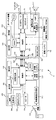
図1に、本実施例のオーディオ・ナビゲーションシステム1の構成を示す。
本実施例のオーディオ・ナビゲーションシステム1は、車両に搭載されたオーディオ装置100と、オーディオ装置100に着脱可能に取り付けられたナビゲーション装置200とを備え、ナビゲーション装置200は、オーディオ装置100にコネクタ部300で接続されている。
FIG. 1 shows a configuration of an audio navigation system 1 according to the present embodiment.
The audio navigation system 1 according to the present embodiment includes an
図2(A)に、オーディオ・ナビゲーションシステム1の外観形状を示す。ナビゲーション装置200は、オーディオ装置100の前面パネル150に嵌め込まれている。また、ナビゲーション装置200は、図2(B)に示すようにオーディオ装置100から取り外して単独で使用することも可能である。オーディオ装置100の前面パネル150には、ナビゲーション装置200の他に、表示部101や、オーディオ装置100を操作可能な操作部102が設けられている。
FIG. 2A shows the external shape of the audio navigation system 1. The
図2(A)に示すオーディオ・ナビゲーションシステム1は、図3に示すように車両の2DIN開口部に収容され、固定される。 The audio navigation system 1 shown in FIG. 2A is housed and fixed in a 2DIN opening of a vehicle as shown in FIG.
図1に戻って、各装置の構成について説明する。オーディオ装置100は、表示部101、操作部102、マイク103、ラジオチューナ104、CDデッキ105、制御部106、RAM(Random Access Memory)107、音声出力部110などを備えている。
Returning to FIG. 1, the configuration of each apparatus will be described. The
オーディオ装置100側の表示部101は、音楽情報、再生時間などを表示させることができる。操作部102はオーディオ装置100で再生する曲を選曲したり、受信する放送番組を選択する等、CDデッキ105やラジオチューナ104を操作することができる。
The
ラジオチューナ104とCDデッキ105とは音源であり、この他にMDデッキやカセットテープレコーダを備えることもできる。ラジオチューナ104とCDデッキ105とのいずれかが操作対象として操作部102で選択されると、制御部106は、選択された音源からの信号を音声出力部110に出力する。
音声出力部110には、制御部106から送られた信号を処理する信号処理部111と、信号を増幅するアンプ112とを備えている。アンプ112で増幅された信号が接続されるスピーカ113から出力される。
The
The
制御部106は、RAM107に格納されたプログラム等を読み込んで、オーディオ装置100の各部を制御する。
マイクはハンズフリーのため、オーディオ装置100側に設けられる。制御部106は、マイクから入力される音声をコネクタ310を介してナビゲーション装置200の無線通信送受信部212に出力する。無線通信送受信部212に出力された音声は、通信先の通信機に送出される。
また、制御部106は、車両に搭載された車載バッテリ10から供給される電源をナビゲーション装置200側に供給する制御を行う。
さらに制御部106は、車両から車速パルス、イルミネーション電源信号、ACC(アクセサリ電源)信号等を入力して、信号に従った処理を行う。車速パルスは、制御部106からナビゲーション装置200側の制御部208に出力される。
The
Since the microphone is hands-free, it is provided on the
Moreover, the
Further, the
ナビゲーション装置200は、表示部201と、操作部202と、地図記憶部203と、電源スイッチ204と、GPSアンテナ205と、スピーカ206と、制御部208と、RAM209と、充電回路210と、内蔵バッテリ211と、無線通信送受信部212と、無線アンテナ213とを有している。
The
GPSアンテナ205は、衛星からのGPS信号を受信するものであり、GPSアンテナ205で受信したGPS信号は、制御部208に出力される。制御部208は、衛星からのGPS信号に基づいて自車位置を割り出す(GPS航法)。
The
地図記憶部203には、地図データが記録されており、地図記憶部203から読み出された地図データは、デコーダ(不図示)で解読される。デコーダは制御部208に接続されており、制御部208は、割り出した自車位置と地図データとを合わせる、いわゆるマップマッチング処理を行う。マップマッチング処理によって、自車位置が正確に示された地図画像データを作成するようになっている。作成した地図画像データは、制御部208の制御によって表示部(メインディスプレイ)201に表示される。
Map data is recorded in the
また、操作部202からの操作信号は、制御部208に入力され、操作信号に応じた処理が制御部208で行われる。例えば、制御部208は、操作部202からの操作指示に基づいて、目的地が設定されると、自車位置から目的地までの最適ルートを探索し、これを誘導ルートとして地図と共に表示部201へ表示する。また、ナビゲーションの音声案内は、制御部208の制御によってスピーカ206から出力される。なお、ナビゲーション装置200がオーディオ装置100に装着されると、ナビゲーション装置200の音声案内は、オーディオ装置100に接続されるスピーカ103から出力される。
この他に制御部208は、操作部202又は102の操作によって、オーディオ装置100側からの音楽情報を表示部(メインディスプレイ)201に表示させることもできる。
An operation signal from the
In addition, the
さらに、ナビゲーション装置200は、オーディオ装置100の制御部106の制御によって供給される電源を内蔵バッテリ211に充電する充電回路210と、ナビゲーション装置200がオーディオ装置100から取り外されたときや、車載バッテリ10からの電源供給がないときに、ナビゲーション装置200に電源を供給する内蔵バッテリ211とを有している。
Furthermore, the
また、ナビゲーション装置200は、無線アンテナ213と、無線通信送受信部212とを備えており、不図示のセンタから渋滞予測データ等の交通情報を取得することができるようになっている。交通情報は、ナビゲーション時の経路選択に利用される。
また、通信先の電話機からの通話音声を受信し、オーディオ装置100に接続されるスピーカ103から通話音声を出力させることで、ハンズフリー機能として利用することができる。
In addition, the
Further, by receiving the call voice from the communication destination telephone and outputting the call voice from the
オーディオ装置100とナビゲーション装置200とは、制御線や、電源線等の複数本の信号線で接続されている。コネクタ部300は、オーディオ装置側のコネクタ310と、ナビゲーション装置側のコネクタ320とを有し、これらが接続されることで、前述した複数本の信号線が接続される。
The
また、コネクタ部300には、コネクタ部300にナビゲーション装置200が接続されているか否か検出する検出回路370が設けられている。検出回路370の構成を図4に示す。
図4に示すトランジスタ350は、ナビゲーション装置200が、ナビゲーション装置200に電源を供給する電源線360に接続されていないときにオフする。このため、オーディオ装置100の制御部106に供給される電圧は0Vになる。電源線360にナビゲーション装置200が接続されると、トランジスタ350がオンされるので、オーディオ装置100の制御部106には、電源からの3.3Vの電圧が供給される。
制御部106は、トランジスタ350と制御部106とを接続するナビゲーション装置検出端子の出力電圧が3.3Vであれば、未接続状態とし、0Vであれば接続状態であると検知する。
In addition, the
The
If the output voltage of the navigation device detection terminal connecting the
さらに、図2に示すようにオーディオ装置100には、取り外しスイッチ(SW)301が設けられており、この取り外しスイッチ301を押下することで、ナビゲーション装置200がオーディオ装置100の前面パネル150から取り外せるような構造となっている。
Further, as shown in FIG. 2, the
本実施例のナビゲーション装置200は、ナビゲーション装置200のオン、オフを切り替えることができる電源スイッチ204を図2(B)に示すように筐体の上面に設けており、オーディオ装置100に取り付けられた状態では電源スイッチ204を操作することができないようになっている。
そこで、車両本体側から供給されるACC電源のオン、オフの切替タイミングと、ナビゲーション装置200のオーディオ装置100への取り付けと、取り外しのタイミングで、ナビゲーション装置200の電源のオンとオフとを切り替える。
なお、以下で説明する電源オンとは、オーディオ装置100、ナビゲーション装置200がいつでも動作可能な状態であることをいい、スタンバイ状態を含むものとする。
The
Therefore, the power of the
The power-on described below means that the
表1には、オーディオ装置100にナビゲーション装置200を取り付けたときのナビゲーション装置200の電源状態を示す。
Table 1 shows a power state of the

まず、ACC電源がオン(オーディオ装置100がオン)で、ナビゲーション装置200が電源オンの状態でオーディオ装置100に取り付けられた場合、ナビゲーション装置200は電源オンの状態を継続したまま、電源の供給源を内蔵バッテリ211から車載バッテリ10に切り替える。また、ナビゲーション装置200は、車載バッテリ10から供給される電源を内蔵バッテリ211に充電する。
次に、ACC電源がオン(オーディオ装置100がオン)で、ナビゲーション装置200が電源オフの状態で取り付けられた場合、オーディオ装置100の制御部106は、車載バッテリ10からの電源を供給して、ナビゲーション装置200の電源をオンさせる。また、ナビゲーション装置200の内蔵バッテリ211への充電も行う。
次に、ACC電源がオフ(オーディオ装置100がオフ)で、ナビゲーション装置200が電源オンの状態で取り付けられた場合、ナビゲーション装置200は、内蔵バッテリ211の電源で駆動させる。
また、ACC電源がオフ(オーディオ装置100がオフ)で、ナビゲーション装置200が電源オフの状態で取り付けられた場合には、オーディオ装置100、ナビゲーション装置200とも電源オフを継続する。
First, when the ACC power source is on (the
Next, when the ACC power source is on (the
Next, when the ACC power source is off (the
When the ACC power is off (the
表2には、オーディオ装置100からナビゲーション装置200を取り外すときのナビゲーション装置200の電源状態を示す。
Table 2 shows the power state of the
まず、ACC電源がオン(オーディオ装置100がオン)で、ナビゲーション装置200が電源オンの状態でオーディオ装置100から取り外された場合、車載バッテリ10からナビゲーション装置200への電源供給を停止し、ナビゲーション装置200を内蔵バッテリ211で駆動させる。
また、ACC電源がオン(オーディオ装置100がオン)で、ナビゲーション装置200が電源オフの状態でオーディオ装置100から取り外された場合、ナビゲーション装置200は電源オフのままで、内蔵バッテリ211への充電を中止する。
次に、ACC電源がオフ(オーディオ装置100がオフ)で、ナビゲーション装置200が電源オンの状態でオーディオ装置100から取り外された場合、ナビゲーション装置200をそのまま内蔵バッテリ211で駆動させる。
次に、ACC電源がオフ(オーディオ装置100がオン)で、ナビゲーション装置200も電源オフの状態でオーディオ装置100から取り外された場合、ナビゲーション装置200は電源オフを継続する。
First, when the ACC power is on (the
Further, when the ACC power is on (the
Next, when the ACC power source is off (the
Next, when the ACC power is off (the
表3には、ナビゲーション装置200がオーディオ装置100に取り付けられている状態で、ACC電源の状態が切り替わったときのナビゲーション装置200の電源状態の変化を示す。
Table 3 shows a change in the power state of the
まず、ナビゲーション装置200の電源がオンで、ACC電源がオフからオン(オーディオ装置100がオフからオン)に切り替わった場合、内蔵バッテリ211で動作させていたナビゲーション装置200を車載バッテリ10からの電源供給で動作させる。同時に車載バッテリ10からの電源で内蔵バッテリ211の充電を行う。
次に、ナビゲーション装置200の電源がオフで、ACC電源がオフからオン(オーディオ装置100がオフからオン)に切り替わった場合、ナビゲーション装置200に車載バッテリ10からの電源を供給してナビゲーション装置200を起動させる。同時に車載バッテリ10からの電源で内蔵バッテリ211の充電を行う。
次に、ナビゲーション装置200の電源がオンで、ACC電源がオンからオフ(オーディオ装置100がオンからオフ)に切り替わった場合、車載バッテリ10からナビゲーション装置200への電源供給を停止し、内蔵バッテリ211の電源でナビゲーション装置200を動作させる。
次に、ナビゲーション装置200の電源がオフで、ACC電源がオンからオフ(オーディオ装置100がオンからオフ)に切り替わった場合、ナビゲーション装置200の電源オフを継続させ、内蔵バッテリ211の充電を停止させる。
First, when the
Next, when the
Next, when the
Next, when the
次に、上述した動作を実現するためのオーディオ装置100の制御部106と、ナビゲーション装置200の制御部208の処理手順を説明する。
Next, processing procedures of the
まず、図5に示すフローチャートを参照しながら、ナビゲーション装置200の接続を検知したオーディオ装置100の制御部106の処理手順を説明する。なお、本フローは、オーディオ装置100に電源が供給され、動作可能な状態である場合に実行される。
オーディオ装置100の制御部106は、ナビゲーション装置200の接続を検知すると(ステップS1)、ナビゲーション装置200の電源がオンされているか否かを判定する(ステップS2)。オーディオ装置100の制御部106は、ナビゲーション装置200の制御部208との通信が可能であるか否かを判定して、ナビゲーション装置200の電源がオンされているか否かを判定する。
ナビゲーション装置200の電源がオンされている場合には(ステップS2/YES)、制御部106は、駆動電源を内蔵バッテリ211から車載バッテリ10に切り替える要求信号をナビゲーション装置200の制御部208に出力する(ステップS3)。制御部106は、ナビゲーション装置200の制御部208との通信が完了すると、車載バッテリ10の電源をナビゲーション装置200に供給する(ステップS4)。
First, the processing procedure of the
When detecting the connection of the navigation device 200 (step S1), the
When the
また、ナビゲーション装置200の電源がオンされていない場合(ステップS2/NO)、制御部106は、ナビゲーション装置200に起動信号を出力してナビゲーション装置200を起動させ(ステップS5)、車載バッテリ10の電源をナビゲーション装置200に供給する(ステップS6)。
When the
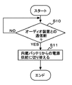
次に、ナビゲーション装置200がオーディオ装置100から切り離された時のナビゲーション装置200の制御部208の処理手順を図6に示すフローチャートを参照しながら説明する。
ナビゲーション装置200の制御部208は、オーディオ装置100との通信が断たれると、オーディオ装置100からナビゲーション装置200が切り離されたことを検知する(ステップS1)。オーディオ装置100からの切り離しを検出すると、ナビゲーション装置200の制御部208は、電源供給を内蔵バッテリ211からの電源に切り替える(ステップS11)。つまり、ナビゲーション装置200は、オーディオ装置100から取り外されると、電源スイッチ204のオン、オフ状態に基づいて、内蔵バッテリ211からの電源供給により動作する。
Next, the processing procedure of the
When communication with the
次に、ナビゲーション装置200がオーディオ装置100に取り付けられた状態で、車両のACC電源がオフからオンに切り替わったときのオーディオ装置100の制御部106の処理手順を図7に示すフローチャートを参照しながら説明する。
車両のACC電源がオフからオンに切り替わり(ステップS21/YES)、オーディオ装置100の電源スイッチがオンされると(ステップS22/YES)、オーディオ装置100の制御部106は、ナビゲーション装置200の電源がオンされているか否かを判定する(ステップS23)。ナビゲーション装置200の電源がオンされている場合には(ステップS23/YES)、制御部106は、駆動電源を内蔵バッテリ211から車載バッテリ10に切り替える要求信号をナビゲーション装置200の制御部208に出力する(ステップS24)。制御部106は、ナビゲーション装置200の制御部208との通信が完了すると、車載バッテリ10の電源をナビゲーション装置200に供給する(ステップS25)。
Next, the processing procedure of the
When the ACC power supply of the vehicle is switched from OFF to ON (step S21 / YES) and the power switch of the
また、ナビゲーション装置200の電源がオンされていない場合(ステップS23/NO)、制御部106は、ナビゲーション装置200に起動信号を出力してナビゲーション装置200を起動させ(ステップS26)、車載バッテリ10の電源をナビゲーション装置200に供給する(ステップS27)。
If the
以上のように本実施例は、オーディオ装置100から取り外して使用されていたナビゲーション装置200が、オーディオ装置100に取り付けられると、ナビゲーション装置の電源をオンするようにした。このため、ユーザは、目的地等を入力したナビゲーション装置を車両に持ち込んでオーディオ装置に搭載すれば、ナビゲーション装置の電源が自動的にオンされるので、ナビゲーション装置をすぐに使うことができ、ユーザの利便性を向上させることができる。
As described above, in this embodiment, when the
また、ナビゲーション装置200の電源をオンした状態で、ナビゲーション装置200をオーディオ装置100から取り外すと、ナビゲーション装置200の電源オンが継続されるので、ユーザはナビゲーション装置200をオーディオ装置100から取り外した後もそのままナビゲーション装置100を使用することができる。
Further, if the
また、ナビゲーション装置200が車載バッテリ10からの電源供給を受けている時には、ナビゲーション装置200の内蔵バッテリ211への充電が行われるので、面倒な操作を伴わずに内蔵バッテリ211の充電を行うことができる。
Further, when the
また、オーディオ装置100の電源(車両のACC電源がオン)されていれば、ナビゲーション装置200は、オーディオ装置100に取り付けた時に電源が入るため、ナビゲーション装置200の電源スイッチをナビの前面に設ける必要がない。このため、ナビゲーション装置200のデザイン性を向上させることができる。また、電源スイッチ204の基板上への配置位置の自由度を上げることができる。
In addition, if the
上述した実施例は本発明の好適な実施の一例である。但し、これに限定されるものではなく、本発明の要旨を逸脱しない範囲内において種々変形実施可能である。
例えば、図5、7に示す動作手順の変形例として、オーディオ装置100側からの要求信号によらず、ナビゲーション装置200側が接続したバッテリの供給状態から起動状態(ON/OFF)を切り替えるようにしてもよい。すなわち、電源の供給を開始すると、ナビゲーション装置200側で自動的に充電を開始する。
また、上述したオーディオ・ナビゲーションシステム1では、オーディオ装置100側の制御部106がメイン制御装置として動作していたが、ナビゲーション装置200側の制御部208をメイン制御装置として動作させることも可能である。
また、本実施例では車載電子装置をオーディオ装置とし、携帯電子装置をナビゲーション装置として説明したが、車載電子装置をナビゲーション装置とし、オーディオ装置を装着するようにしてもよい。
The above-described embodiment is an example of a preferred embodiment of the present invention. However, the present invention is not limited to this, and various modifications can be made without departing from the scope of the present invention.
For example, as a modification of the operation procedure shown in FIGS. 5 and 7, the activation state (ON / OFF) is switched from the battery supply state connected to the
In the audio navigation system 1 described above, the
In this embodiment, the in-vehicle electronic device is described as an audio device and the portable electronic device is described as a navigation device. However, the in-vehicle electronic device may be used as a navigation device and the audio device may be attached.
1 オーディオ・ナビゲーションシステム
10 車載バッテリ
100 オーディオ装置
101、201 表示部
102、202 操作部
103、207 マイク
104 ラジオチューナ
105 CDデッキ
106、208 制御部
107、209 RAM
110 音声出力部
111 信号処理部
112 AMP
113、206 スピーカ
200 ナビゲーション装置
204 電源SW
205 GPSアンテナ
210 充電回路
211 内蔵バッテリ
212 無線通信送受信部
213 無線アンテナ
300 コネクタ部
301 取り外しSW
DESCRIPTION OF SYMBOLS 1
110
113, 206
205
Claims (9)
前記車載電子装置に対して着脱自在に装着される携帯電子装置とを有し、
前記車載電子装置は、自装置が動作可能な状態であるときに前記携帯電子装置の装着を検出すると、前記携帯電子装置を動作可能な状態にさせることを特徴とする車載用電子システム。 An in-vehicle electronic device mounted on the vehicle;
A portable electronic device that is detachably attached to the on-vehicle electronic device;
The in-vehicle electronic system is characterized in that when the in-vehicle electronic device detects that the portable electronic device is attached when the own device is operable, the in-vehicle electronic device makes the portable electronic device operable.
前記車載電子装置から取り外されているときには、前記電源スイッチの操作状態によって電源のオンと、オフとを切り替えることを特徴とする請求項1から4のいずれか一項記載の車載用電子システム。 The portable electronic device has a power switch at a position where it can be operated when it is removed from the on-vehicle electronic device,
5. The vehicle-mounted electronic system according to claim 1, wherein when the power supply switch is detached from the vehicle-mounted electronic device, the power supply is switched on and off according to the operation state of the power switch.
前記携帯電子装置の装着を検出する検出手段と、
前記携帯電子装置の装着を検出すると、前記携帯電子装置の電源をオンさせる制御手段と、
を有することを特徴とする車載電子装置。 An in-vehicle electronic device mounted on a vehicle and capable of detachably mounting a portable electronic device,
Detecting means for detecting attachment of the portable electronic device;
When detecting the mounting of the portable electronic device, control means for turning on the power of the portable electronic device;
An on-vehicle electronic device comprising:
前記制御手段は、前記携帯電子装置の装着を検出すると、前記携帯電子装置に前記車両本体からの電源を供給することを特徴とする請求項6記載の車載電子装置。 The in-vehicle electronic device operates by receiving power supply from the vehicle body,
The on-vehicle electronic device according to claim 6, wherein the control unit supplies power from the vehicle body to the portable electronic device when detecting the mounting of the portable electronic device.
前記携帯電子装置の装着を検出するステップと、
前記携帯電子装置の装着を検出すると、前記携帯電子装置の電源をオンさせるステップと、
を有することを特徴とする携帯電子装置の電源制御方法。 A power control method for a portable electronic device that is detachably attached to an in-vehicle electronic device,
Detecting the mounting of the portable electronic device;
Detecting the mounting of the portable electronic device, turning on the portable electronic device; and
A power supply control method for a portable electronic device.
Priority Applications (18)
| Application Number | Priority Date | Filing Date | Title |
|---|---|---|---|
| JP2006327663A JP2008137559A (en) | 2006-12-04 | 2006-12-04 | On-vehicle electronic system, on-vehicle electronic apparatus, and power supply control method of portable electronic apparatus |
| US11/645,629 US7638896B2 (en) | 2006-12-04 | 2006-12-27 | In-vehicle electronic system, in-vehicle electronic apparatus and method of controlling power supply of portable electronic device |
| TW96144756A TWI338641B (en) | 2006-12-04 | 2007-11-26 | In-vehicle electronic system, in-vehicle electronic apparatus and method of controlling power supply of portable electronic device |
| KR1020070124480A KR20080051090A (en) | 2006-12-04 | 2007-12-03 | In-vehicle electronic system, in-vehicle electronic apparatus and method of controlling power supply of portable electronic device |
| EP07122203.8A EP1931047B1 (en) | 2006-12-04 | 2007-12-04 | Electronic system and electronic apparatus |
| EP07122200.4A EP1931044B1 (en) | 2006-12-04 | 2007-12-04 | Electronic apparatus and electronic system |
| EP20070122204 EP1931048B1 (en) | 2006-12-04 | 2007-12-04 | Electronic apparatus, electronic system and method of controlling audio output |
| EP07122196.4A EP1931040B1 (en) | 2006-12-04 | 2007-12-04 | Electronic apparatus and electronic system |
| EP20070122197 EP1931041B1 (en) | 2006-12-04 | 2007-12-04 | Electronic apparatus and electronic system |
| EP07122206.1A EP1931050B1 (en) | 2006-12-04 | 2007-12-04 | In-vehicle electronic system and in-vehicle electronic apparatus |
| EP20070122201 EP1931045B1 (en) | 2006-12-04 | 2007-12-04 | In-vehicle electronic apparatus and in-vehicle electronic system |
| EP07122202A EP1931046A3 (en) | 2006-12-04 | 2007-12-04 | In-vehicle electronic apparatus and in-vehicle electronic system |
| EP20070122194 EP1931038B1 (en) | 2006-12-04 | 2007-12-04 | Electronic system, electronic apparatus and method of operating audio unit |
| EP20070122195 EP1931039B1 (en) | 2006-12-04 | 2007-12-04 | Electronic apparatus, electronic system and method of controlling sound output |
| CN2007101971050A CN101198245B (en) | 2006-12-04 | 2007-12-04 | In-vehicle electronic system and in-vehicle electronic apparatus, method for controlling power of portable electronic device |
| EP07122199A EP1931043A3 (en) | 2006-12-04 | 2007-12-04 | Attachment and detachment mechanism for portable electronic device |
| EP07122205.3A EP1931049B1 (en) | 2006-12-04 | 2007-12-04 | In-vehicle electronic system, in-vehicle electronic apparatus and method of controlling power supply of portable electronic device |
| EP07122198.0A EP1931042B1 (en) | 2006-12-04 | 2007-12-04 | Electronic apparatus and electronic system |
Applications Claiming Priority (1)
| Application Number | Priority Date | Filing Date | Title |
|---|---|---|---|
| JP2006327663A JP2008137559A (en) | 2006-12-04 | 2006-12-04 | On-vehicle electronic system, on-vehicle electronic apparatus, and power supply control method of portable electronic apparatus |
Publications (2)
| Publication Number | Publication Date |
|---|---|
| JP2008137559A true JP2008137559A (en) | 2008-06-19 |
| JP2008137559A5 JP2008137559A5 (en) | 2010-09-09 |
Family
ID=39474877
Family Applications (1)
| Application Number | Title | Priority Date | Filing Date |
|---|---|---|---|
| JP2006327663A Pending JP2008137559A (en) | 2006-12-04 | 2006-12-04 | On-vehicle electronic system, on-vehicle electronic apparatus, and power supply control method of portable electronic apparatus |
Country Status (5)
| Country | Link |
|---|---|
| US (1) | US7638896B2 (en) |
| JP (1) | JP2008137559A (en) |
| KR (1) | KR20080051090A (en) |
| CN (1) | CN101198245B (en) |
| TW (1) | TWI338641B (en) |
Cited By (2)
| Publication number | Priority date | Publication date | Assignee | Title |
|---|---|---|---|---|
| WO2008146782A1 (en) * | 2007-05-29 | 2008-12-04 | Sanyo Electric Co., Ltd. | On-vehicle system, navigation device, and reproduction device |
| JP2012018183A (en) * | 2011-10-05 | 2012-01-26 | Sanyo Electric Co Ltd | On-vehicle system, navigation device, and playback device |
Families Citing this family (11)
| Publication number | Priority date | Publication date | Assignee | Title |
|---|---|---|---|---|
| JP2008141076A (en) * | 2006-12-04 | 2008-06-19 | Fujitsu Ten Ltd | Attaching/detaching device of mobile electronic equipment |
| JP4961264B2 (en) * | 2007-05-29 | 2012-06-27 | 三洋電機株式会社 | In-vehicle system, navigation device, and playback device |
| JP2009248935A (en) * | 2008-04-10 | 2009-10-29 | Fujitsu Ten Ltd | Vehicle-mounted device |
| US9231438B2 (en) | 2008-10-01 | 2016-01-05 | Aspen Avionics, Inc. | Airborne power system disconnect system and method |
| TWI365572B (en) * | 2008-12-31 | 2012-06-01 | Remote controllable power outlet apparatus with grouping capability and grouping remote control method | |
| US9146900B2 (en) * | 2012-02-21 | 2015-09-29 | Htc Corporation | Method for activating application, handheld electronic apparatus and car system |
| US9862049B2 (en) * | 2014-06-27 | 2018-01-09 | Illinois Tool Works Inc. | System and method of welding system operator identification |
| JP2016179801A (en) * | 2015-03-25 | 2016-10-13 | 株式会社デンソー | On-board system |
| US9731600B1 (en) * | 2016-04-11 | 2017-08-15 | John White | Vehicle picture frame |
| US10880023B2 (en) * | 2018-08-03 | 2020-12-29 | Gracenote, Inc. | Vehicle-based media system with audio advertisement and external-device action synchronization feature |
| JP7298520B2 (en) * | 2020-03-10 | 2023-06-27 | トヨタ自動車株式会社 | Getting off assistance device |
Citations (9)
| Publication number | Priority date | Publication date | Assignee | Title |
|---|---|---|---|---|
| JPH01300775A (en) * | 1988-05-30 | 1989-12-05 | Matsushita Electric Ind Co Ltd | On-vehicle video acoustic device |
| JPH04239251A (en) * | 1991-01-11 | 1992-08-27 | Toshiba Corp | Radio telephony equipment adaptor |
| JPH0646000A (en) * | 1992-05-25 | 1994-02-18 | Pioneer Electron Corp | Car stereo |
| JPH06164468A (en) * | 1992-11-25 | 1994-06-10 | Mitsubishi Electric Corp | Adaptor unit for cordless telephone set |
| JP3050447U (en) * | 1997-11-18 | 1998-07-14 | 相鎬 崔 | Car audio with hands-free function |
| JP2000207670A (en) * | 1999-01-08 | 2000-07-28 | Nec Mobile Commun Ltd | House-to-house receiver |
| JP2001264075A (en) * | 2000-03-14 | 2001-09-26 | Alpine Electronics Inc | Navigation system |
| JP2002293165A (en) * | 2000-06-29 | 2002-10-09 | Denso Corp | Vehicle information display method and device therefor |
| JP2005173653A (en) * | 2003-12-05 | 2005-06-30 | Sony Corp | Electronic equipment |
Family Cites Families (82)
| Publication number | Priority date | Publication date | Assignee | Title |
|---|---|---|---|---|
| US650925A (en) * | 1900-03-16 | 1900-06-05 | Martin Bruner | Combined corn-harvester and farm-wagon. |
| JPS6034094Y2 (en) | 1979-03-26 | 1985-10-11 | オリンパス光学工業株式会社 | Muting circuit |
| JPS626764Y2 (en) | 1981-06-23 | 1987-02-17 | ||
| DE3445668C1 (en) | 1984-12-14 | 1986-01-02 | Daimler-Benz Ag, 7000 Stuttgart | Control device for a vehicle guidance system |
| JPS6318184A (en) | 1986-07-09 | 1988-01-26 | Shigeru Matsumori | Automatic starter for automobile engine |
| US5592389A (en) | 1990-12-03 | 1997-01-07 | Ans, Llp | Navigation system utilizing audio CD player for data storage |
| JP2697961B2 (en) | 1991-01-21 | 1998-01-19 | 富士通テン株式会社 | Portable navigation system |
| JP2547786Y2 (en) | 1991-04-12 | 1997-09-17 | パイオニア株式会社 | Grill attachment / detachment device |
| JP2635504B2 (en) | 1993-09-03 | 1997-07-30 | 富士通テン株式会社 | Front detachable structure |
| JP3268476B2 (en) | 1993-11-05 | 2002-03-25 | クラリオン株式会社 | Panel attachment / detachment mechanism |
| JP3225718B2 (en) | 1993-12-06 | 2001-11-05 | ソニー株式会社 | Electronic equipment and detachable devices |
| JPH07304396A (en) | 1994-03-14 | 1995-11-21 | Alpine Electron Inc | Demountable type electronic equipment |
| JP3305104B2 (en) | 1994-03-14 | 2002-07-22 | アルパイン株式会社 | Operating devices for electronic equipment |
| JPH087977A (en) | 1994-06-17 | 1996-01-12 | Fujitsu Ten Ltd | Electronic apparatus furnished with detachable controlling element |
| JP3376813B2 (en) | 1995-03-20 | 2003-02-10 | アイシン・エィ・ダブリュ株式会社 | Navigation device and detachable unit for detachable unit |
| JP2002328026A (en) | 1995-03-20 | 2002-11-15 | Aisin Aw Co Ltd | Navigation system |
| US5705975A (en) | 1995-03-24 | 1998-01-06 | Clarion Co., Ltd. | Anti-theft device for electronic apparatuses |
| JP3537531B2 (en) | 1995-03-24 | 2004-06-14 | クラリオン株式会社 | Detachable mechanism to prevent theft of in-vehicle electronic devices |
| US5627547A (en) | 1995-04-07 | 1997-05-06 | Delco Electronics Corporation | Mapless GPS navigation system in vehicle entertainment system |
| US5774828A (en) | 1995-04-07 | 1998-06-30 | Delco Electronics Corporation | Mapless GPS navigation system with user modifiable data base |
| US5964821A (en) | 1995-04-07 | 1999-10-12 | Delco Electronics Corporation | Mapless GPS navigation system with sortable destinations and zone preference |
| JPH08297030A (en) | 1995-04-25 | 1996-11-12 | Sony Corp | Display device and av navigation system |
| US5845282A (en) * | 1995-08-07 | 1998-12-01 | Apple Computer, Inc. | Method and apparatus for remotely accessing files from a desktop computer using a personal digital assistant |
| CN1086865C (en) | 1995-10-04 | 2002-06-26 | 大发工业株式会社 | Information transmitting and receiving apparatus |
| US5794164A (en) | 1995-11-29 | 1998-08-11 | Microsoft Corporation | Vehicle computer system |
| US6519463B2 (en) | 1996-02-28 | 2003-02-11 | Tendler Cellular, Inc. | Location based service request system |
| JPH102001A (en) | 1996-06-15 | 1998-01-06 | Okajima Kogyo Kk | Grating |
| KR980004919A (en) | 1996-06-21 | 1998-03-30 | 배순훈 | Front panel loading device for car audio |
| JPH1047982A (en) | 1996-08-06 | 1998-02-20 | Sony Corp | Instrument and method for measuring location, device and method for navigation, information service method, and automobile |
| JP3893647B2 (en) | 1996-09-30 | 2007-03-14 | マツダ株式会社 | Navigation device |
| US6208932B1 (en) | 1996-09-30 | 2001-03-27 | Mazda Motor Corporation | Navigation apparatus |
| JPH10135669A (en) | 1996-10-31 | 1998-05-22 | Fujitsu Ten Ltd | Electronic apparatus |
| JPH10199220A (en) | 1997-01-16 | 1998-07-31 | Clarion Co Ltd | Recording medium reproducing apparatus and method of controlling the same |
| US6009355A (en) | 1997-01-28 | 1999-12-28 | American Calcar Inc. | Multimedia information and control system for automobiles |
| US6119060A (en) | 1997-03-31 | 2000-09-12 | Mazda Motor Corporation | Electronic equipment apparatus and electronic equipment assembly |
| US6091956A (en) | 1997-06-12 | 2000-07-18 | Hollenberg; Dennis D. | Situation information system |
| US6093977A (en) | 1997-06-17 | 2000-07-25 | Mazda Motor Corporation | Vehicle electronic equipment apparatus and its assembling method |
| JPH1142986A (en) | 1997-07-29 | 1999-02-16 | Harness Sogo Gijutsu Kenkyusho:Kk | Vehicular electrical equipment structure |
| US6405049B2 (en) | 1997-08-05 | 2002-06-11 | Symbol Technologies, Inc. | Portable data terminal and cradle |
| US6055478A (en) | 1997-10-30 | 2000-04-25 | Sony Corporation | Integrated vehicle navigation, communications and entertainment system |
| US6243645B1 (en) | 1997-11-04 | 2001-06-05 | Seiko Epson Corporation | Audio-video output device and car navigation system |
| DE19803178A1 (en) | 1998-01-28 | 1999-07-29 | Bosch Gmbh Robert | Car radio with removable operating control device |
| JPH11289173A (en) | 1998-04-02 | 1999-10-19 | Fujitsu Ten Ltd | Enclosure structure |
| GB2336489A (en) | 1998-04-14 | 1999-10-20 | Ford Motor Co | Latch for removable front portion of vehicle cassette radio |
| JP3889510B2 (en) | 1998-05-21 | 2007-03-07 | アルパイン株式会社 | In-vehicle device control system |
| US6150925A (en) | 1998-06-03 | 2000-11-21 | Intel Corporation | Connecting devices to in-car personal computers |
| US6417786B2 (en) | 1998-11-23 | 2002-07-09 | Lear Automotive Dearborn, Inc. | Vehicle navigation system with removable positioning receiver |
| JP3566879B2 (en) | 1999-04-27 | 2004-09-15 | アルパイン株式会社 | Handheld PC and in-vehicle equipment to which it is mounted |
| US7346374B2 (en) | 1999-05-26 | 2008-03-18 | Johnson Controls Technology Company | Wireless communications system and method |
| JP2001015936A (en) | 1999-07-02 | 2001-01-19 | Alpine Electronics Inc | Detaching/attaching apparatus for electronic device |
| JP3647325B2 (en) | 1999-08-06 | 2005-05-11 | アルパイン株式会社 | Operation member attaching / detaching device |
| JP2001141471A (en) | 1999-11-18 | 2001-05-25 | Toyota Motor Corp | Route guide system for vehicle |
| EP1077362B1 (en) | 1999-08-17 | 2004-05-26 | Toyota Jidosha Kabushiki Kaisha | Route guiding apparatus |
| DE19939631A1 (en) | 1999-08-20 | 2001-02-22 | Nokia Mobile Phones Ltd | Multimedia unit with removable operator control for installation in vehicle, uses operator-control surface as touch-sensitive display operating together with processor system |
| WO2001065720A2 (en) | 2000-02-29 | 2001-09-07 | Kabushiki Kaisha Kenwood | Data distribution system and method, and electric equipment to be used therefor |
| JP2001239895A (en) | 2000-02-29 | 2001-09-04 | Kenwood Corp | Electronic instrument and panel |
| KR100727904B1 (en) * | 2000-06-09 | 2007-06-13 | 삼성전자주식회사 | Chip enbedded trading card, recording/reproducing apparatus therefor, and communication realizing method therefor |
| JP2003037514A (en) | 2001-07-25 | 2003-02-07 | Fujitsu Ten Ltd | Digital broadcast receiver |
| JP2002074922A (en) | 2000-08-28 | 2002-03-15 | Pioneer Electronic Corp | On-vehicle audio and/or video apparatus |
| JP3846189B2 (en) | 2000-12-14 | 2006-11-15 | 松下電器産業株式会社 | Navigation device |
| JP2002267461A (en) | 2001-03-12 | 2002-09-18 | Kenwood Corp | Navigation system, navigation method, and on-vehicle navigation system utilizing portable terminal |
| US7216242B2 (en) | 2001-03-16 | 2007-05-08 | Dualcor Technologies, Inc. | Personal electronics device with appliance drive features |
| US7184003B2 (en) | 2001-03-16 | 2007-02-27 | Dualcor Technologies, Inc. | Personal electronics device with display switching |
| US6785531B2 (en) | 2001-03-22 | 2004-08-31 | Visteon Global Technologies, Inc. | Dual-function removable reversable unit for radio and telephone |
| WO2002082405A1 (en) | 2001-04-03 | 2002-10-17 | Magellan Dis, Inc. | Vehicle navigation system with portable personal computer |
| JP4346831B2 (en) | 2001-04-20 | 2009-10-21 | パイオニア株式会社 | Detaching mechanism and information recording / reproducing apparatus using the same |
| DE10134717C2 (en) | 2001-07-17 | 2003-05-28 | Daimler Chrysler Ag | Method for configuring an information system |
| JP3680773B2 (en) | 2001-07-25 | 2005-08-10 | 松下電器産業株式会社 | Navigation device |
| JP3989712B2 (en) | 2001-11-20 | 2007-10-10 | アルパイン株式会社 | In-vehicle acoustic system |
| JP3594011B2 (en) | 2001-11-30 | 2004-11-24 | 株式会社デンソー | Navigation device |
| US6545637B1 (en) | 2001-12-20 | 2003-04-08 | Garmin, Ltd. | Systems and methods for a navigational device with improved route calculation capabilities |
| US7215950B2 (en) | 2002-01-23 | 2007-05-08 | General Motors Corporation | Method of telematics unit configuration and activation using vehicle control buttons |
| EP1342620A3 (en) | 2002-02-26 | 2003-12-17 | Lg Electronics Inc. | Front panel operating apparatus and method for an audio device |
| US7006845B2 (en) | 2002-04-03 | 2006-02-28 | General Motors Corporation | Method and system for interfacing a portable transceiver in a telematics system |
| JP3986869B2 (en) | 2002-04-11 | 2007-10-03 | パイオニア株式会社 | Electronics |
| JP2003315065A (en) | 2002-04-26 | 2003-11-06 | Denso Corp | Navigation apparatus |
| US6681176B2 (en) | 2002-05-02 | 2004-01-20 | Robert Bosch Gmbh | Method and device for a detachable navigation system |
| US7418276B2 (en) | 2002-06-26 | 2008-08-26 | Motorola, Inc. | Activation system and method for establishing a cellular voice communication through a radio system |
| US6993615B2 (en) | 2002-11-15 | 2006-01-31 | Microsoft Corporation | Portable computing device-integrated appliance |
| JP2004234794A (en) | 2003-01-31 | 2004-08-19 | Toshiba Corp | Reproducing device and reproducing method, recording device and recording method, av system |
| EP1727019A1 (en) | 2005-05-27 | 2006-11-29 | Mitac Technology Corp. | In-car video/audio computer module |
| JP2008141076A (en) | 2006-12-04 | 2008-06-19 | Fujitsu Ten Ltd | Attaching/detaching device of mobile electronic equipment |
-
2006
- 2006-12-04 JP JP2006327663A patent/JP2008137559A/en active Pending
- 2006-12-27 US US11/645,629 patent/US7638896B2/en active Active
-
2007
- 2007-11-26 TW TW96144756A patent/TWI338641B/en not_active IP Right Cessation
- 2007-12-03 KR KR1020070124480A patent/KR20080051090A/en not_active Application Discontinuation
- 2007-12-04 CN CN2007101971050A patent/CN101198245B/en not_active Expired - Fee Related
Patent Citations (9)
| Publication number | Priority date | Publication date | Assignee | Title |
|---|---|---|---|---|
| JPH01300775A (en) * | 1988-05-30 | 1989-12-05 | Matsushita Electric Ind Co Ltd | On-vehicle video acoustic device |
| JPH04239251A (en) * | 1991-01-11 | 1992-08-27 | Toshiba Corp | Radio telephony equipment adaptor |
| JPH0646000A (en) * | 1992-05-25 | 1994-02-18 | Pioneer Electron Corp | Car stereo |
| JPH06164468A (en) * | 1992-11-25 | 1994-06-10 | Mitsubishi Electric Corp | Adaptor unit for cordless telephone set |
| JP3050447U (en) * | 1997-11-18 | 1998-07-14 | 相鎬 崔 | Car audio with hands-free function |
| JP2000207670A (en) * | 1999-01-08 | 2000-07-28 | Nec Mobile Commun Ltd | House-to-house receiver |
| JP2001264075A (en) * | 2000-03-14 | 2001-09-26 | Alpine Electronics Inc | Navigation system |
| JP2002293165A (en) * | 2000-06-29 | 2002-10-09 | Denso Corp | Vehicle information display method and device therefor |
| JP2005173653A (en) * | 2003-12-05 | 2005-06-30 | Sony Corp | Electronic equipment |
Cited By (3)
| Publication number | Priority date | Publication date | Assignee | Title |
|---|---|---|---|---|
| WO2008146782A1 (en) * | 2007-05-29 | 2008-12-04 | Sanyo Electric Co., Ltd. | On-vehicle system, navigation device, and reproduction device |
| JP2008296598A (en) * | 2007-05-29 | 2008-12-11 | Sanyo Electric Co Ltd | On-vehicle system, navigation system, and reproduction device |
| JP2012018183A (en) * | 2011-10-05 | 2012-01-26 | Sanyo Electric Co Ltd | On-vehicle system, navigation device, and playback device |
Also Published As
| Publication number | Publication date |
|---|---|
| KR20080051090A (en) | 2008-06-10 |
| CN101198245B (en) | 2012-02-29 |
| TW200902352A (en) | 2009-01-16 |
| US7638896B2 (en) | 2009-12-29 |
| US20080129114A1 (en) | 2008-06-05 |
| CN101198245A (en) | 2008-06-11 |
| TWI338641B (en) | 2011-03-11 |
Similar Documents
| Publication | Publication Date | Title |
|---|---|---|
| JP2008137559A (en) | On-vehicle electronic system, on-vehicle electronic apparatus, and power supply control method of portable electronic apparatus | |
| JP4842785B2 (en) | In-vehicle electronic system and in-vehicle electronic device | |
| US7765046B2 (en) | In-vehicle electronic apparatus and in-vehicle electronic system | |
| JP5113602B2 (en) | Electronic equipment and electronic system | |
| TW200902937A (en) | In-vehicle electronic apparatus and in-vehicle electronic system | |
| JP5141361B2 (en) | Vehicle system and program | |
| US20060212213A1 (en) | Navigation System | |
| EP1931049B1 (en) | In-vehicle electronic system, in-vehicle electronic apparatus and method of controlling power supply of portable electronic device | |
| KR100911677B1 (en) | Electronic apparatus, electronic system and method of controlling audio output | |
| KR100906134B1 (en) | Electronic apparatus, electronic system and method of controlling sound output | |
| JP2008171542A (en) | Electronic system, electronic apparatus and method of operating audio unit | |
| JP2009248936A (en) | Electronic device | |
| JP2009248935A (en) | Vehicle-mounted device | |
| KR100740199B1 (en) | Car A/V apparatus and portable multimedia apparatus connectable to car A/V apparatus | |
| JP2009035025A (en) | Electronic device and system | |
| JP2009035026A (en) | Electronic device and system | |
| JP2009202762A (en) | In-vehicle device | |
| JP2009023531A (en) | Electronic device and electronic system | |
| JP2008235996A (en) | Onboard-portable electronic apparatus |
Legal Events
| Date | Code | Title | Description |
|---|---|---|---|
| A621 | Written request for application examination |
Free format text: JAPANESE INTERMEDIATE CODE: A621 Effective date: 20091120 |
|
| A521 | Written amendment |
Free format text: JAPANESE INTERMEDIATE CODE: A523 Effective date: 20100722 |
|
| A977 | Report on retrieval |
Free format text: JAPANESE INTERMEDIATE CODE: A971007 Effective date: 20110922 |
|
| A131 | Notification of reasons for refusal |
Free format text: JAPANESE INTERMEDIATE CODE: A131 Effective date: 20111004 |
|
| A521 | Written amendment |
Free format text: JAPANESE INTERMEDIATE CODE: A523 Effective date: 20111130 |
|
| A131 | Notification of reasons for refusal |
Free format text: JAPANESE INTERMEDIATE CODE: A131 Effective date: 20120508 |
|
| A02 | Decision of refusal |
Free format text: JAPANESE INTERMEDIATE CODE: A02 Effective date: 20130402 |