JP2007533973A - Balance wheel, balance spring, other components and assemblies for mechanical vibration system and manufacturing method - Google Patents
Balance wheel, balance spring, other components and assemblies for mechanical vibration system and manufacturing method Download PDFInfo
- Publication number
- JP2007533973A JP2007533973A JP2006534811A JP2006534811A JP2007533973A JP 2007533973 A JP2007533973 A JP 2007533973A JP 2006534811 A JP2006534811 A JP 2006534811A JP 2006534811 A JP2006534811 A JP 2006534811A JP 2007533973 A JP2007533973 A JP 2007533973A
- Authority
- JP
- Japan
- Prior art keywords
- balance
- balance wheel
- thermal expansion
- coefficient
- rim
- Prior art date
- Legal status (The legal status is an assumption and is not a legal conclusion. Google has not performed a legal analysis and makes no representation as to the accuracy of the status listed.)
- Pending
Links
Images


Classifications
-
- B—PERFORMING OPERATIONS; TRANSPORTING
- B21—MECHANICAL METAL-WORKING WITHOUT ESSENTIALLY REMOVING MATERIAL; PUNCHING METAL
- B21F—WORKING OR PROCESSING OF METAL WIRE
- B21F35/00—Making springs from wire
- B21F35/04—Making flat springs, e.g. sinus springs
-
- F—MECHANICAL ENGINEERING; LIGHTING; HEATING; WEAPONS; BLASTING
- F16—ENGINEERING ELEMENTS AND UNITS; GENERAL MEASURES FOR PRODUCING AND MAINTAINING EFFECTIVE FUNCTIONING OF MACHINES OR INSTALLATIONS; THERMAL INSULATION IN GENERAL
- F16F—SPRINGS; SHOCK-ABSORBERS; MEANS FOR DAMPING VIBRATION
- F16F1/00—Springs
- F16F1/36—Springs made of rubber or other material having high internal friction, e.g. thermoplastic elastomers
- F16F1/366—Springs made of rubber or other material having high internal friction, e.g. thermoplastic elastomers made of fibre-reinforced plastics, i.e. characterised by their special construction from such materials
- F16F1/3665—Wound springs
-
- G—PHYSICS
- G04—HOROLOGY
- G04B—MECHANICALLY-DRIVEN CLOCKS OR WATCHES; MECHANICAL PARTS OF CLOCKS OR WATCHES IN GENERAL; TIME PIECES USING THE POSITION OF THE SUN, MOON OR STARS
- G04B17/00—Mechanisms for stabilising frequency
- G04B17/04—Oscillators acting by spring tension
- G04B17/06—Oscillators with hairsprings, e.g. balance
- G04B17/066—Manufacture of the spiral spring
Abstract
本出願は、リリースエージェント(110)を用いて空間が設けられ、連続繊維又はセラミックから形成されるバランススプリング(100)を円柱状のフォーマ(90)のまわりに巻くことにより前記バランススプリングを作る方法を開示する。セラミック材料を回転するフォーマ、マンドレル又はプレートに適用し、その後に熱処理することにより、好ましくはセラミック材料のバランススプリングを作る方法がまた開示される。異なる熱膨張係数を有する構成要素の特有の配置により、温度の上昇とともに減少する慣性モーメントを有するバランスホイールがまた開示される。非磁性セラミック又は連続繊維製のバランススプリングと、6×10⁻⁶K−1より小さい熱膨張係数を有する材料から形成され、複数の非磁性の平衡又は計時用の付属物とを有する非磁性バランスホイールとを備えた機械式振動システムがまた開示される。The present application provides a method for making a balance spring by wrapping a balance spring (100) formed of continuous fibers or ceramic around a cylindrical former (90) provided with a space using a release agent (110). Is disclosed. Also disclosed is a method of making a balance spring, preferably of ceramic material, by applying the ceramic material to a rotating former, mandrel or plate followed by heat treatment. Also disclosed is a balance wheel having a moment of inertia that decreases with increasing temperature due to the unique arrangement of components having different coefficients of thermal expansion. Non-magnetic balance comprising a non-magnetic ceramic or continuous fiber balance spring and a plurality of non-magnetic balance or timekeeping appendages formed from a material having a coefficient of thermal expansion less than 6 × 10 −6 K −1 A mechanical vibration system comprising a wheel is also disclosed.
Description
(技術分野)
本発明は、精密な時計学上の時間を計測する機械式振動システム又は他の精密器械に使用するためのバランスホイール(balance wheel)に関する。本発明は、特に機械式時計の振動システムに適用されるが、これに限定されるものではない。
(Technical field)
The present invention relates to a balance wheel for use in a mechanical vibration system or other precision instrument that measures precise horological time. The present invention is applied particularly to a vibration system of a mechanical timepiece, but is not limited thereto.
(背景技術)
時計用のバランスホイールは、従来、主として金属から作られていた。バランススプリング(balance spring)は、バランスホイールを振動させるとともに等時性の振動周期で振動させるために配設される。
(Background technology)
Conventionally, a balance wheel for a watch has been mainly made of metal. The balance spring is arranged to vibrate the balance wheel and vibrate with an isochronous vibration cycle.
使用される金属は、たいていのセラミックに比べて高い線膨張係数を一般に有する。これは、例えば、金属(Fe−Ni、Cu−Be、Cu−Zn、Cu−Au、Ni又はこれらの組み合わせ)から作られるバランスホイールと、Fe−Ni合金、Fe−Mn−C又は他の鋼派生合金(steel derivative alloy)から作られるバランススプリングとを有する前記システムにおいて標準であった。2003年7月10日に出願され、2004年1月22に公開され、引用することによりここに組み入れられる本出願人による先願PCT/GB03/003000は、熱と磁気の影響をこの関係において改良する又は解決することができ、それにより高精度を達成することができる新しいバランススプリング材料を開示している。 The metal used generally has a higher coefficient of linear expansion than most ceramics. This includes, for example, balance wheels made of metal (Fe—Ni, Cu—Be, Cu—Zn, Cu—Au, Ni or combinations thereof) and Fe—Ni alloys, Fe—Mn—C or other steels. Standard in the system with a balance spring made from a steel derivative alloy. Applicant's earlier application PCT / GB03 / 003000, filed July 10, 2003, published January 22, 2004 and incorporated herein by reference, improves the effects of heat and magnetism in this regard. Disclosed is a new balance spring material that can be made or solved, thereby achieving high accuracy.
バランスホイールとバランススプリングに対する熱の影響の作用は、同じではない。バランスホイールとバランススプリングとの関係において熱及び熱弾性の特性は、等しい態様で変化しない。 The effect of thermal effects on the balance wheel and balance spring is not the same. In the relationship between the balance wheel and the balance spring, the thermal and thermoelastic properties do not change in an equal manner.
関連する関係にある項(term)を不変にするための最も成功した以前の試み(1912年にシー・イー・ギヨーム(C.E.Guillaume)により発明されたバイメタル式補正バランスホイールと鋼製バランススプリングシステム、1943年にハミルトン(Hamilton)により発明された鋼と結合した高精度ニッケル鉄ベース合金のスプリングと不変鋼(invar)製の楕円形バランスホイール)は、有効な熱特性(ニッケル鉄合金が、異常なヤング率の変化を有する)にもかかわらず、磁気に敏感な材料の使用を必要としていた。この後者の影響は、ヤング率の安定性を妨げ、計時の精度(等時性)に悪影響をもたらす。 The most successful previous attempt to make the relevant terms invariant (bimetallic corrected balance wheel and steel balance spring system, invented by CEGuillaume in 1912, High precision nickel iron base alloy spring combined with steel invented by Hamilton in 1943 and elliptical balance wheel made of invariant steel (invar) has effective thermal properties (nickel iron alloy is unusual Despite the change in Young's modulus, it required the use of magnetically sensitive materials. This latter effect hinders the stability of Young's modulus and adversely affects the accuracy of timekeeping (isochronism).
振動周期Tのための式は、以下に表される:

T:振動周期、I:バランスホイールの慣性モーメント、G:バランススプリングのトルク
The equation for the vibration period T is expressed as follows:
T: Vibration period, I: Moment of inertia of balance wheel, G: Torque of balance spring
前記振動システムは、磁気及び熱の性質の変動に左右される。バランスホイールが金属から作られる場合、バランスホイールは温度の増加とともに膨張する。ニッケル鉄合金から最も一般的に作られるバランススプリングもまた、温度の増加とともに膨張する。 The vibration system is sensitive to variations in magnetic and thermal properties. When the balance wheel is made of metal, the balance wheel expands with increasing temperature. Balance springs, most commonly made from nickel iron alloys, also expand with increasing temperature.
線膨張率は、ミリメートル/度ケルビンについて1/1000の単位で測定され、例えば、銅、Cuの場合には+17×10−6K−1と表され、α係数として知られている。 The linear expansion coefficient is measured in units of 1/1000 for millimeter / degree Kelvin, and is expressed as + 17 × 10 −6 K −1 in the case of copper and Cu, for example, and is known as an α coefficient.
熱弾性係数は、温度の上昇に対する材料の弾性の変化の傾向を表す。 The thermoelastic coefficient represents the tendency of the elasticity of a material to change with increasing temperature.
ニッケル鉄合金は、十分に消磁される場合には40℃まで‘異常’といわれる正の熱弾性係数を有する。しかしながら、磁気蓄積(magnetic accumulation)は、温度に対するr(バランスホイールの回転半径)及び√E(バランススプリングの弾性率の平方根)の変化を表す図1のグラフに示すように、低温においてEとrの項の発散を引き起こす、この閾値を低くする。これは、振動システムの等時性における合成誤差の原因である。 Nickel-iron alloys have a positive thermoelastic coefficient that is said to be 'abnormal' up to 40 ° C when fully demagnetized. However, the magnetic accumulation is such that E and r at low temperatures, as shown in the graph in FIG. This threshold is lowered to cause divergence of the term. This is a source of synthesis errors in isochronism of the vibration system.
バランスホイールは、物理的寸法に影響を及ぼす熱変動によってのみ一般に影響を及ぼされるのに対し、バランススプリングは、物理的寸法及び弾性(ヤング率)の両方に影響を及ぼす熱及び磁気の両方の変動によって影響を及ぼされる。 Balance wheels are generally only affected by thermal variations that affect physical dimensions, whereas balance springs are both thermal and magnetic variations that affect both physical dimensions and elasticity (Young's modulus). Is influenced by.
(発明の概要)
計時についての改良した性能のために、これらの負の作用がなくなる又は最小限まで低減される。本発明者は、バランススプリング、特にFe−Ni製バランススプリングのヤング率が温度及び磁気により影響を及ぼされることと、バランススプリングの磁気蓄積が計時に悪影響を有することに注目した。本発明者は、前記スプリングにおけるこれらの変化が、振動システムの誤差の大部分(75%)を占めることに注目した。その残りの誤差のほとんどは、バランスホイール内の熱誘導変化(thermally induced change)によるものである。
(Summary of Invention)
Due to the improved performance with respect to timing, these negative effects are eliminated or reduced to a minimum. The present inventor has noted that the Young's modulus of balance springs, particularly Fe-Ni balance springs, is affected by temperature and magnetism, and that the magnetic accumulation of balance springs has an adverse effect on timekeeping. The inventors have noted that these changes in the spring account for the majority (75%) of the vibration system error. Most of the remaining errors are due to thermally induced changes in the balance wheel.
本発明の態様は、添付する特許請求の範囲に規定される。本発明、好ましい特徴及び本発明の別の態様の背後にある理論の考察が、以下に記述される。 Aspects of the invention are defined in the appended claims. A discussion of the theory behind the invention, preferred features, and other aspects of the invention is described below.
関係[1]内に含まれる変数は、以下に表される:
温度及び磁気の変動は、バランススプリング及びバランスホイールの膨張及び収縮の作用並びにバランススプリングの弾性の変化から得られるT(振動周期)に影響を与える。
The variables included in relation [1] are represented as follows:
Variations in temperature and magnetism affect the T (vibration period) resulting from the effects of expansion and contraction of the balance spring and balance wheel and the elasticity of the balance spring.
バランススプリングのトルクは、以下の寸法、すなわち、長さl、高さh、厚さe及びヤング率Eの関数である。 The torque of the balance spring is a function of the following dimensions: length l, height h, thickness e and Young's modulus E.
バランスホイールの慣性モーメントIは、半径rと(一定のままである)質量Mの関数であり、以下に表される:
![]()
![]()
ヤング率係数Eは、温度及び磁気の作用の変動とともに変化する。 The Young's modulus coefficient E changes with variations in temperature and magnetic action.
例えば本発明者によるPCT/GB03/003000に開示されるもののように、動作温度範囲(0−40℃)において線形の熱弾性変化を備えた非磁気感受性(non-magnetically sentive)及び熱安定性(thermically stable)を有するバランススプリングが選択される場合には、まだ解決されるべき熱誘導変化が、バランスホイールに存在する。 For example, non-magnetically sentive and thermal stability with linear thermoelastic change in the operating temperature range (0-40 ° C.) as disclosed in PCT / GB03 / 003000 by the present inventor ( If a balance spring with thermically stable is selected, there is a heat-induced change in the balance wheel that still has to be resolved.
これは、バランスホイールにおいて正しい材料選択が行われる場合にのみ起こり得るものであり、その運動性能とその静的及び動的な平衡及び調整についての正しい知識が理解され、その製造と時計において一度調節することを可能とする。 This can only happen if the correct material selection is made on the balance wheel, the correct knowledge about its kinematic performance and its static and dynamic balance and adjustment is understood and adjusted once in its manufacture and watch It is possible to do.
温度変化により影響を及ぼされる前記等式内の変数は、一定の関係にさせる必要があり、簡略化して以下の式で表すことができる。
![]()
rは前記バランスホイールの回転半径であり、Eは前記スプリングのヤング率である。
The variables in the equation that are affected by temperature changes need to be in a fixed relationship and can be simplified and represented by the following equations.
![]()
r is the rotation radius of the balance wheel, and E is the Young's modulus of the spring.
前記ホイールの回転半径とこれまで機械式振動システムに使用された材料からなるスプリングのヤング率との関係式は、[4]で表される通りである。 The relational expression between the radius of rotation of the wheel and the Young's modulus of the spring made of the material used so far in the mechanical vibration system is as shown in [4].
これらの項は線形の関係にはないが、この関係は、(振動周期Tの等時性を保つために)一定である必要がある。 Although these terms are not in a linear relationship, this relationship needs to be constant (in order to maintain isochronism of the vibration period T).
質量が温度の変化により影響を受けず、また、慣性モーメントは[3]で表されるMr2の結果(product)であるので、バランス体(balance)が達成しなければならない残りの補正は、熱により膨張又は収縮するrの関数として計算される。 Since the mass is not affected by changes in temperature and the moment of inertia is the product of Mr 2 expressed in [3], the remaining correction that the balance must achieve is: Calculated as a function of r that expands or contracts due to heat.
従来、金属合金製のバランススプリングは、熱弾性率の非線形調整を有していた(温度変化に対するヤング率の変化は、√E曲線により表される)。単一金属から作られるバランスホイールは、温度の上昇に対するr値の線形増加を有しているが、同一のグラフにプロットされた温度に対するr及び√Eの変化についての重ね合わせられた曲線は、δEの値がδrの値の解を与える、あるいは図示された√Eの値の曲線が直線rと交差する、2点での交わりを示す。最も幅広く離れている2つの曲線間の不一致は、図1のグラフに示すように中間温度誤差2として知られている。 Conventionally, a balance spring made of a metal alloy has nonlinear adjustment of thermoelastic modulus (change in Young's modulus with respect to temperature change is represented by a √E curve). A balance wheel made from a single metal has a linear increase in r-value with increasing temperature, but the superimposed curves for changes in r and √E with respect to temperature plotted in the same graph are: It shows the intersection at two points where the value of δE gives a solution of the value of δr, or the curve of the value of √E shown intersects the straight line r. The discrepancy between the two most widely separated curves is known as the intermediate temperature error 2 as shown in the graph of FIG.
従来、この問題を解決することができるバランスホイール及びバランススプリングは、磁気感受性材料から作られており、現在の磁気汚染のレベルにより決して適していない。 Traditionally, balance wheels and balance springs that can solve this problem are made from magnetically sensitive materials and are by no means more suitable for current levels of magnetic contamination.
前記関係r/√Eに対する解を与えるために、先ず、線形の熱弾性変化を有するスプリングが必要であり、前記スプリングの特性は、前記関係がr/Eの方へ向かうような一定の変化を可能とし、また、温度の上昇に対する前記スプリングの軸方向の膨張係数αが負である。 In order to give a solution for the relationship r / √E, first a spring with a linear thermoelastic change is required, and the characteristics of the spring have a constant change so that the relationship is towards r / E. The expansion coefficient α in the axial direction of the spring with respect to the temperature rise is negative.
本発明者が発明したように(また、その製造方法が特許請求の範囲及び後の説明にて記載されるように)、スプリングについて正しい選択をした前記システムの性能を改良するために、バランススプリングのための材料選択が、磁気の影響を受けない材料、最も好ましくは低いα係数を有する材料からである必要があり、前記スプリング材料の軸方向のα係数と反対の符号を有する同一の符号ではない非常に低いα係数である場合には、温度をX軸にとり、名目上の単位(nominal unit)の長さ及び弾性率をY軸にとり、実線が温度に対するrの変化を表し、破線が温度に対するEの変化を表す図2のグラフの上部3に示すように、好ましくは線形であるとともに0℃から80℃において1%より小さい低い熱弾性率の傾向を有する。最も好ましくは、バランススプリング材料は、前記スプリングの熱弾性率傾向と同一符号を有するα係数からなる。
In order to improve the performance of the system with the right choice for the spring, as invented by the inventor (and as its manufacturing method is described in the claims and in the following description), the balance spring The material selection for the material must be from a material that is not magnetically affected, most preferably a material having a low alpha coefficient, and with the same sign having a sign opposite to the axial alpha coefficient of the spring material. In the case of a very low α coefficient, the temperature is taken on the X axis, the nominal unit length and elastic modulus are taken on the Y axis, the solid line represents the change in r with respect to the temperature, and the broken line represents the temperature. As shown in the
等方性であるか異方性であるかにかかわらないα係数及び膨張特性とヤング率はすべて、関係[2]で計算され慎重に検討される。あらゆる変数を無視する場合、すなわち、それらが運転中に前記システムに関係している態様が、その他の変数及びそれらの相互関係を引用することなく、また理解することなく無視される場合、改良された性能を得られないであろう。 All α coefficients, expansion properties and Young's modulus, whether isotropic or anisotropic, are all calculated and carefully considered in relation [2]. Improved if all variables are ignored, i.e. the manner in which they relate to the system during operation is ignored without quoting and understanding other variables and their interrelationships. You will not get the performance you want.
一般に、温度が1℃上昇した場合の計時変化(U)を示す式は、
![]()
である。
従って、適切な材料を慎重に選択して、バランスホイールの熱膨張係数α1とバランススプリングの熱膨張係数α2と熱弾性係数Eの適正値を選択することで、Uをゼロに向かわせることができる。
In general, the equation showing the time change (U) when the temperature rises by 1 ° C
![]()
It is.
Therefore, by choosing appropriate materials carefully, by selecting the proper value of the thermal expansion coefficient of the balance wheel alpha 1 and the thermal expansion coefficient of the balance spring alpha 2 and thermoelastic coefficient E, to direct the U to zero Can do.
熱弾性率が周囲範囲(ambient range)において線形の態様で変化するとともに最小限であり、また、前記スプリングがバランス体の一部に正又は負の向きにある残りの態様(residual manner)にて補償するように求める選択されたバランススプリング材料において、以下の解決法が提案される。 Thermoelastic modulus varies and is minimal in a linear manner in the ambient range, and in a residual manner where the spring is in a positive or negative orientation on a part of the balance body In the selected balance spring material that is sought to compensate, the following solutions are proposed.
本発明の第1の態様は、時計又は他の精密器械に使用するためのバランススプリングを作る方法であって、連続繊維又はセラミックから形成される、ある長さの非磁性バランススプリング材料を円柱状のフォーマのまわりに巻くステップと、その巻いたものの隣接する層が互いに付着することを抑制するように又は前記隣接する層が付着している互いからの解放を容易にするようにリリースエージェントを使用するステップと、巻かれた前記バランススプリング材料を熱処理するステップとを備えているバランススプリングを作る方法を提供する。 A first aspect of the invention is a method of making a balance spring for use in a watch or other precision instrument, wherein a length of non-magnetic balance spring material formed from continuous fiber or ceramic is cylindrical. Use a release agent to wrap around the former and to prevent the adjacent layers of the roll from sticking to each other or to facilitate release from each other to which the adjacent layers are attached And a method of making a balance spring comprising the steps of: heat treating the wound balance spring material.
本発明の第2の態様は、時計又は他の精密器械に使用するためのバランススプリングを作る方法であって、受容プレート、フォーマ又はマンドレルのまわりに、又はその内部に、あるいはその上に、ある長さの非磁性バランススプリング材料を配置するステップと、前記バランススプリング材料を熱処理するステップと、前記フォーマ、受容プレート又はマンドレルから前記バランススプリング材料を取り除き、平らなアルキメデスのバランススプリングを形成するステップとを備えているバランススプリングを作る方法を提供する。 A second aspect of the present invention is a method of making a balance spring for use in a watch or other precision instrument, around, within or on a receiving plate, former or mandrel. Placing a length of non-magnetic balance spring material; heat treating the balance spring material; removing the balance spring material from the former, receiving plate or mandrel to form a flat Archimedes balance spring; A method of making a balance spring comprising:
本発明の第3の態様は、時計又は他の精密器械用の機械式振動システムに使用するための非磁性バランスホイールであって、前記バランスホイールの慣性モーメントが温度の増加とともに減少するように調整された、異なる熱膨張係数を有する2つの異なる材料の構成要素を備えている非磁性バランスホイールを提供する。 A third aspect of the present invention is a non-magnetic balance wheel for use in a mechanical vibration system for a watch or other precision instrument, wherein the moment of inertia of the balance wheel is adjusted to decrease with increasing temperature. A non-magnetic balance wheel comprising two different material components having different coefficients of thermal expansion.
前記第3の態様は、時計又は他の精密器械に使用するためのバランスホイールであって、正である第1の熱膨張係数を有する第1の非磁性材料から形成される1つ若しくはそれ以上のクロスメンバを有するバランスホイールアームと、前記バランスホイールアームに取り付けられ、第2の熱膨張係数を有する第2の非磁性材料から形成されるリムと、を備え、前記第2の熱膨張係数が、前記第1の熱膨張係数より小さく、それにより、温度の増加が、前記1つ若しくはそれ以上のクロスメンバの長さの増加と、前記バランスホイールの慣性モーメントの減少をもたらす前記リムの半径方向内方へのたわみとを引き起こすバランスホイールを提供する本発明の第4の態様の形態をとってもよい。 The third aspect is a balance wheel for use in a watch or other precision instrument, one or more formed from a first non-magnetic material having a first coefficient of thermal expansion that is positive. A balance wheel arm having a cross member, and a rim attached to the balance wheel arm and formed of a second nonmagnetic material having a second coefficient of thermal expansion, wherein the second coefficient of thermal expansion is A radial direction of the rim that is less than the first coefficient of thermal expansion, whereby an increase in temperature results in an increase in the length of the one or more cross members and a decrease in the moment of inertia of the balance wheel It may take the form of the fourth aspect of the invention to provide a balance wheel that causes inward deflection.
本発明の第3の態様は、時計又は他の精密器械に使用するためのバランスホイールであって、第1の熱膨張係数を有する第1の非磁気感受性材料から形成される1つ若しくはそれ以上のクロスメンバを有するバランスホイールアームと、正である第2の熱膨張係数を有する第2の非磁気感受性材料から形成される複数の凹状セグメントと、を備え、前記第2の熱膨張係数が、前記第1の熱膨張係数より小さく、それにより、前記凹状セグメントが、温度の増加とともに前記バランスホイールの慣性モーメントの減少を引き起こすように半径方向内方へ更に延びるバランスホイールを提供する本発明の第5の形態をとってもよい。 A third aspect of the invention is a balance wheel for use in a watch or other precision instrument, one or more formed from a first non-magnetically sensitive material having a first coefficient of thermal expansion. A balance wheel arm having a plurality of cross members and a plurality of concave segments formed from a second non-magnetically sensitive material having a second coefficient of thermal expansion that is positive, wherein the second coefficient of thermal expansion is: A first aspect of the invention that provides a balance wheel that is less than the first coefficient of thermal expansion so that the concave segment extends further radially inward to cause a decrease in the moment of inertia of the balance wheel with increasing temperature. It may take the form of 5.
本発明の第6の態様は、時計装置又は他の精密器械に使用するための機械式振動システムであって、平らな渦巻状又は螺旋状の形態の非磁性バランススプリングと、非磁性バランスホイールと、を備え、前記バランススプリングが、セラミック材料又は連続繊維を有する材料から形成され、前記バランスホイールが、6×10⁻⁶K−1より小さい熱膨張係数を有する材料から形成され、前記バランスホイールが、前記バランスホイールの慣性モーメントに対する調整を行うための複数の非磁性の平衡又は計時付属物を更に備えている機械式振動システムを提供する。 A sixth aspect of the present invention is a mechanical vibration system for use in a timepiece or other precision instrument, comprising a non-magnetic balance spring in the form of a flat spiral or spiral, a non-magnetic balance wheel, Wherein the balance spring is formed from a ceramic material or a material having continuous fibers, the balance wheel is formed from a material having a thermal expansion coefficient less than 6 × 10 −6 K −1 , and the balance wheel is A mechanical vibration system further comprising a plurality of non-magnetic balanced or timed accessories for adjusting the moment of inertia of the balance wheel.
本発明の第7の態様は、時計又は他の精密器械用の機械式振動システムに使用するためのバランスホイールアッセンブリ(balance wheel assembly)であって、6×10⁻⁶K−1より小さい熱膨張係数を有する等方性非磁性材料から一体的に形成される一体化したバランススタッフとバランスホイールとを備えているバランスホイールアッセンブリを提供する。 A seventh aspect of the invention is a balance wheel assembly for use in a mechanical vibration system for a watch or other precision instrument having a thermal expansion of less than 6 × 10 −6 K −1. Provided is a balance wheel assembly including an integrated balance staff and a balance wheel integrally formed from an isotropic nonmagnetic material having a coefficient.
本発明の第8に態様は、時計又は他の精密器械用の機械式振動システムに使用するためのアッセンブリ(assembly)であって、バランススタッフと、前記バランススタッフと一体的に形成され、バランスホイールリムを支持するための1つ若しくはそれ以上のクロスメンバと、を備え、前記クロスメンバとバランススタッフとが、6×10⁻⁶K−1より小さい熱膨張係数を有する非磁性材料から一体的に形成されるアッセンブリを提供する。 An eighth aspect of the present invention is an assembly for use in a mechanical vibration system for a watch or other precision instrument, the balance staff being formed integrally with the balance staff, and a balance wheel. One or more cross members for supporting the rim, wherein the cross member and the balance stuff are integrally made of a non-magnetic material having a thermal expansion coefficient smaller than 6 × 10 −6 K −1. An assembly to be formed is provided.
本発明の第9の態様は、前記バランスリムと前記1つ若しくはそれ以上のクロスメンバとがともにグリーン状態にある場合に、結合又は熱処理によって前記バランスリムを前記1つ若しくはそれ以上のクロスメンバに取り付けることにより、本発明の第8の態様に記載のアッセンブリを形成する方法を提供する。 According to a ninth aspect of the present invention, when the balance rim and the one or more cross members are both in a green state, the balance rim is joined to the one or more cross members by bonding or heat treatment. By attaching, a method of forming an assembly according to the eighth aspect of the invention is provided.
本発明の第10の態様は、時計又は他の精密装置に使用するためのバランスホイールアッセンブリを形成する方法であって、セラミック製のスタッフとバランスホイールとがグリーン状態にある場合に、別々のセラミック製のスタッフとバランスホイールとをともに取り付けるステップと、結合又は熱処理プロセスを用いて、前記セラミック製のスタッフとバランスホイールとをともに固定するステップと、を備え、前記バランスホイールとバランススタッフとが、非磁性であり、6×10⁻⁶K−1より小さい熱膨張係数を有するバランスホイールアッセンブリを形成する方法を提供する。 A tenth aspect of the present invention is a method of forming a balance wheel assembly for use in a watch or other precision device, wherein the ceramic stuff and balance wheel are in a green state and separate ceramics. Attaching the ceramic staff and the balance wheel together, and fixing the ceramic staff and the balance wheel together using a bonding or heat treatment process, the balance wheel and the balance staff being non- A method is provided for forming a balance wheel assembly that is magnetic and has a coefficient of thermal expansion less than 6 × 10 −6 K −1 .
本発明の更なる態様及び好ましい特徴が、以下の説明と特許請求の範囲に見られる。 Additional aspects and preferred features of the present invention are found in the following description and claims.
本発明の実施形態及び実施例が、ほんの一例として添付図面を参照して以下に説明される。 Embodiments and examples of the present invention will now be described, by way of example only, with reference to the accompanying drawings.
(詳細な説明)
本発明の種々の実施形態は、バランスホイールとバランススプリングとから構成される機械式振動システムのバランスホイールに関し、前記バランスホイール及び/又はバランススプリングは、好ましくは、非磁気感受性を有し、決してそればかりではないが、好ましくは、以下の群、すなわち、窒化アルミニウム、アルミノケイ酸ガラス、アルミナシリカボリア(alumina silica boria)、炭化ホウ素、窒化ホウ素、シリカ、ケイ素、二酸化ケイ素、窒化ケイ素、(安定化)ジルコニア、カリウム・アルミナ・モスコバイト(potassium alumina muscovite)、(ルビー及びサファイアを含む)酸化アルミニウム、ダイヤモンド又は人工的に生成されたダイヤモンド、押出成形又は静水圧成形グラファイト、熱硬化性又は熱可塑性ポリマーあるいはモノマー、ガラス、カーボン、又はガラス状炭素からのセラミック材料を有する、好ましくは低い(+6×10⁻⁶K−1より小さい)α係数を有する材料から全体として又は組み合わせとして構成されている。また、前記材料は、非磁気感受性金属間化合物からなる群から選択されてもよい。選択された材料は、熱硬化性又は熱可塑性ポリマー、セラミック、ガラス、カーボン、あるいはガラス状炭素のマトリクス内の連続する又は分散した繊維あるいはナノ粒子の形態であってもよい。更に、前記材料は、揮発性、水性又はポリマーの物質から作られる結合剤の中にある、好ましくはセラミックである加熱プレス又は反応結合した(reaction bonded)粉末、微小粉末又は微小球体あるいはテープキャスティング材料(tape casting meterial)の形態であってもよい。更に、前記材料は、熱硬化性又は熱可塑性ポリマー、セラミック、ガラス、カーボン、又はガラス状炭素のマトリクス内の黒鉛連続炭素繊維(graphitic continuous carbon fibre)又は非連続炭素繊維、カーボンナノファイバー又はチューブ、ポリマー又はセラミック繊維から構成される複合材料であってもよい。
(Detailed explanation)
Various embodiments of the present invention relate to a balance wheel of a mechanical vibration system comprising a balance wheel and a balance spring, said balance wheel and / or balance spring preferably having non-magnetic sensitivity and never Preferably, but not limited to, the following groups: aluminum nitride, aluminosilicate glass, alumina silica boria, boron carbide, boron nitride, silica, silicon, silicon dioxide, silicon nitride, (stabilized) Zirconia, potassium alumina muscovite, aluminum oxide (including ruby and sapphire), diamond or artificially produced diamond, extruded or isostatically formed graphite, thermoset or thermoplastic polymer or monomer Glass, carbon, or with a ceramic material from glassy carbon, which is preferably constructed as a whole or a combination of a material having a low (+ 6 × 10 -6 K -1 smaller) alpha factor. The material may be selected from the group consisting of non-magnetically sensitive intermetallic compounds. The selected material may be in the form of continuous or dispersed fibers or nanoparticles in a matrix of thermosetting or thermoplastic polymer, ceramic, glass, carbon, or glassy carbon. Furthermore, the material is in a binder made from a volatile, aqueous or polymeric substance, preferably a hot press or reaction bonded powder, fine powder or microsphere or tape casting material, preferably ceramic. (Tape casting meterial) may be used. Further, the material may be a graphitic continuous carbon fiber or non-continuous carbon fiber, carbon nanofiber or tube in a matrix of thermosetting or thermoplastic polymer, ceramic, glass, carbon, or glassy carbon, It may be a composite material composed of polymer or ceramic fibers.
バランスホイールに対して熱影響により与えられる変化を最小限にさせる必要がある。 Changes to the balance wheel due to thermal effects need to be minimized.
まず第1に、バランスホイールの材料選択は、好ましくは、+1.0×10⁻⁶K−1より小さいα係数を有する単相結晶体又は混合相結晶体及び残留ガラス成分からなる低いα係数を有する等方性セラミック材料、例えば石英ガラス(二酸化ケイ素96−99%)であることが提案される。これは、温度に対するrの限られた変化を確保する。 First of all, the material selection of the balance wheel is preferably a low α coefficient consisting of a single phase crystal or mixed phase crystal having an α coefficient smaller than + 1.0 × 10 −6 K −1 and a residual glass component. It is proposed to have an isotropic ceramic material, for example quartz glass (silicon dioxide 96-99%). This ensures a limited change of r with temperature.
バランスホイールは、好ましくは円形及びディスク状であるが、円形であるものに限定するものではない。バランスホイールは、その周縁部に垂直に突出する浅いリム(rim)からなる付加質量(additional mass)を備えてあるいは備えていないで形成され得る。好ましくは円形である上側表面と好ましくは円形である下側表面とは、平行である。図4は、回転軸に沿うバランススタッフ(balance staff)を受容するための開口部35を有する平面ディスク状のバランスホイール30の実施例を示す。また、バランスホイールは、バランススタッフと一体的であってもよい。
The balance wheel is preferably circular and disc-shaped, but is not limited to a circular one. The balance wheel can be formed with or without an additional mass consisting of a shallow rim projecting perpendicularly to its periphery. The upper surface, preferably circular, and the lower surface, preferably circular, are parallel. FIG. 4 shows an embodiment of a planar disc-shaped
本発明の1つの態様は、低いα係数を有し、バランスウェイト(balance weight)と一体化され組み込まれる平衡及び計時付属物(poising and timing appendages)を備えた平らなバランスホイール、又は、好ましくは1つの等方性材料組成から一体的に作られるバランスホイールとバランススタッフに関する。 One aspect of the present invention is a flat balance wheel with a low alpha coefficient and with balancing and timing appendages integrated into and incorporated with a balance weight, or preferably The present invention relates to a balance wheel and a balance staff which are integrally formed from one isotropic material composition.
バランスホイールには、好ましくは、バランスホイール30の回転中心軸35から同一半径の円周上に等しい距離離れて取り付けられる同一の付属物5が配設されており、前記付属物5は2つ以上であり、最大ではバランスホイールの縁部近くに等しい間隔で配置された前記付属物からなる連続的なリングを形成してもよい。各付属物5は、温度の増加とともに、中心点から等しい質量分布、最も好ましくはバランスホイールの回転平面と平行である前記付属物の円形平面内において等しい質量分布を可能とするように配置され、形作られる。
Preferably, the balance wheel is provided with the
前記付属物5は、バランスホイールと同一若しくはそれ以上の密度を有する材料から構成され、Mrにより表されるバランスホイール30の慣性モーメントを決めることができ、また、精密時計及び他の器械の調整において知られているようにバランスホイールの静的及び動的平衡を決めることができる。
The
かかる付属物5は、精密時計の調整技術において知られているように、バランスホイールの静的平衡のために、前記材料のごく一部を通常規則的に移動させることができる金属又は非金属の非磁気感受性材料から作られてもよい。
Such an
図3及び5は、図4の付属物と類似する付属物を有しているが、特有の少し異なる付属物15、16及び5a、6を(付加的に又は代替的に)有するバランスホイールの別の形態の実施例を示している。これらのバランスホイールは、以下にさらに詳しく説明する。
3 and 5 have an attachment similar to that of FIG. 4 but with (in addition or alternatively) a unique slightly
また、前記付属物5、5aは、バランスホイール30の回転中心軸35に対する付属物の一部又は全部の質量中心の有効半径を減少又は増加させることにより、Mrの結果を増加又は減少させることができる。この特徴は、‘バネのない(フリースプラング:free-sprung)’振動システム(スプリングの長さ、ひいてはバランスホイールの振動周期を制御するためにカーブピン(curb pin)を必要としないシステム)において前記バランス体の振動数を調整するのに必要である。
Further, the
これは、バランスリム(balance rim)に半径方向に取り付けられたタイミングスクリュ(timing screw)6、7によって行うことができる。タイミングスクリュ6、タイミングウェイト(timing weight)及び/又はスクリュアッセンブリあるいは偏心ウェイト又はスクリュ7は、好ましくは個々の付属物アッセンブリに組み込まれる。これらは、バランススタッフ軸に平行に(図4aの場合のように)、あるいは垂直に(図3aの場合のように)、あるいは平行且つ垂直に(図5の場合のように)位置付けることができ、平らなバランスホイールの端部近くに、又はバランスホイールのリム上に、あるいはあらゆる形状のクロスメンバ及びリム上に取り付けられる。バランスホイールの回転軸に平行に回転可能なタイミングスクリュ又は調整部材(adjusting member)を備えた付属物5は、回転可能な軸状部(stem)26上に偏心ヘッド25を有する。前記回転軸に垂直な調整部材(例えばタイミングスクリュ)6は、偏心していない。
This can be done by means of timing
前記付属物及びタイミングスクリュヘッドは、抵抗係数を低減するために空気力学的外形であるように形成される。 The appendages and timing screw heads are formed to have an aerodynamic profile to reduce the coefficient of resistance.
図4aに示されるようなバランスホイールは、熱弾性率(E)の低い正の線形変化の影響を補償することができる。 A balance wheel as shown in FIG. 4a can compensate for the effects of positive linear changes in low thermoelastic modulus (E).
バランススプリングが、温度誤差を解決するために、線形である‘標準の’負の熱弾性傾向(−E)を有する第2の場合には、温度の上昇とともに減少するMrの結果を有するのがよい。バランススプリングの低減される弾性作用は、慣性モーメントの減少により補償され、(バランスホイールの振動周期)Tは、影響を受けないままである。 In the second case, where the balance spring has a 'standard' negative thermoelastic tendency (-E) that is linear to resolve the temperature error, it has a Mr result that decreases with increasing temperature. Good. The reduced elastic action of the balance spring is compensated by a reduction of the moment of inertia and (balance wheel vibration period) T remains unaffected.
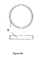
これは、好ましくは2つの方法で達成することができる。これらの第1は、バランスホイールについて組み合わせ材料を使用するものであり、単一又は多数の部分からなる十分に剛性のあるバランスホイールアーム(balance wheel arm)が、前述した適切な材料から得られる+αの熱係数を有する非磁性材料から作られ、(バランスホイールアームにある)1つの若しくは複数のクロスメンバ8は、温度の増加に対して伸びる。クロスメンバの長さが増加すると、あまり剛性のないバランスリム9を内方へたわませる。参照数字は、かかるバランスホイールの実施例を示す図3aを引用する。図8の実施例にはただ1つのクロスメンバがあるが、原則的にはもっと多数であってもよい。
This can preferably be achieved in two ways. The first of these is to use a combination material for the balance wheel, where a sufficiently rigid balance wheel arm consisting of a single or multiple parts is obtained from the appropriate material described above + α One or more crossmembers 8 (in the balance wheel arm) are made from a non-magnetic material having a thermal coefficient of When the length of the cross member increases, the
バランスホイールリム9は、1つのクロスメンバ又は等間隔に配置される複数のクロスメンバ8に取り付けられ、好ましくは、低い線形熱係数を有する十分に可撓性のある非磁性材料から構成される。好ましくは、この低い線形熱係数は負であり、最も好ましくは、1つ若しくは複数のクロスメンバの正の線形熱係数(+α)より大きい大きさであり、前述した材料及び連続炭素繊維、ポリアラミド繊維及び液晶ポリエステル又はポリエステル/アミド共重合体を含む材料において使用することができる。従って、温度の増加に対してバランスホイールリム9の円周が減少し、十分に可撓性を有することが、クロスメンバ8の取付部の間の中間点12において前記バランスホイールリムの内方へのたわみ(deflection)を可能にする。この実施例では、付属物5a、15、16は、中間点12にあるが、平衡(equipoise)が達せられるならば前記リムのその他の位置にあってもよい。
The
図5は、好ましくは負の線形熱係数(−α)を有する1つ若しくは複数のバランスホイールクロスメンバ8と、45度−180度の円弧からなる凹状のバランスホイールリムセグメント10から構成され、好ましくはより大きい正の線形熱係数(+α)を有するバランスホイールリムを使用することにより、同じ作用がどのように達せられるかについての実施例を示す。前記リムの凹状セグメント(concave segment)10の端部は、位置11において、1つ若しくは複数のクロスメンバ8に回転中心35から等しい半径で取り付けられる。温度の上昇に対するリムセグメント10の正の線形膨張は、図5の矢印12に示すように、前記円弧の中心を回転中心35の方へ移動させる。従って、逆円弧(inverted arc)リムセグメント10の中心12に取り付けられた主要付属物(mass appendage)15、16は、回転中心35の方へ運ばれる。1つ若しくは複数のクロスメンバが負の線形熱膨張係数(−α)を有する場合には、前記クロスメンバは、温度の上昇とともに収縮する。また、クロスメンバは、凹状のリムセグメントの熱係数より小さい低い正の熱係数(+α)を有することができ、かかる場合には、クロスメンバは膨張するが、前記リムセグメントより小さいことにより、結果として前記のように半径方向内方へ移動する。更に、凹状セグメントがリムを形成することは本質的ではなく、凹状セグメントは、別の挿入物として設けてもよい。例えば、1つ若しくは複数のクロスメンバと、クロスメンバに取り付けられクロスメンバより大きい熱膨張係数を有する前記リムの内部にある2つ若しくはそれ以上の別の凹状セグメントとに対して同じ−又は異なる−材料からなる円形のリムを有することが可能である。例えば、プラスティック材料製の凹状の挿入物が、従来の真鍮製バランスホイールのリムの内部に取り付けられ、プラスティック材料製の挿入物は、好ましくはそれに取り付けられる非磁性タイミングウェイトを有する。
FIG. 5 is comprised of one or more balance
この最後の2つの構成(図3a及び5に示す実施例)の結果として、有効半径rが減少し、従ってMrの結果が減少する。温度X度で所定のMrの結果を有するバランスリムに平衡して配置される平衡及び計時主要付属物が、温度の上昇とともに同時に回転中心の方へ移動することにより、その結果は、X+n度においてM(r−n)になる。 As a result of this last two configurations (the embodiment shown in FIGS. 3a and 5), the effective radius r is reduced and thus the Mr result is reduced. The balance and timekeeping main appendages placed in balance on a balance rim with a given Mr result at temperature X degrees are moved towards the center of rotation at the same time as the temperature rises, so that the result is X + n degrees M (r−n).
前記半径の変化率は、バランスホイールクロスメンバに取り付けられる位置の間にあるバランスホイールリムの円弧又は逆円弧上のすべての位置において同じではないので、バランスホイールリム上の前記付属物の相対位置及び大きさ並びに数を調整することにより、Mrの結果の変化を正確に決定することができる。 The rate of change of the radius is not the same at every position on the balance wheel rim arc or reverse arc between the positions attached to the balance wheel cross member, so the relative position of the appendages on the balance wheel rim and By adjusting the size as well as the number, changes in the Mr result can be accurately determined.
選択される材料を好適に選択して、また組み合わせて、所定の温度上昇に対する負の変化率δr又は逆に湾曲したリムの場合には正の変化率δrにより増えた質量Mが、バランススプリングの負の熱弾性率傾向の作用を無効にし、図2のグラフの下側部分のライン4に示すように残りの温度誤差が解決される。破線は、温度の変化に対するEの変化を示し、実線はrの変化を示す。 The selected material is preferably selected and combined so that the mass M increased by the negative rate of change δr for a given temperature rise or, in the case of a curved rim, positive rate of change δr, The effect of the negative thermoelasticity trend is negated and the remaining temperature error is resolved as shown in line 4 in the lower portion of the graph of FIG. A broken line indicates a change in E with respect to a change in temperature, and a solid line indicates a change in r.
半径(ラジアル:radial)方向(回転軸に垂直)に向きを合わせられたタイミングスクリュは、Mrの結果を精密に調整するために特別に形作られた工具の係合及び解放を容易にするように成形されてもよい。特に、図7a及び7bに示すようなタイミングスクリュは、軸状部26とヘッド28とを備えている。前記軸状部とともに図7bの側面図において、また(軸状部が視界から隠れた)図7aの平面図において示すようなヘッド28は、(前記軸状部から離れた)先端に向かって先細になり、スパナ型の回転工具と係合する複数のスプライン(spline)13を有する。好ましくは、タイミングスクリュのヘッドは、円錐形状であり、先端まで先細であってもなくてもよい。この技術はまた、平行なタイミングスクリュ7に適用されてもよい。
A timing screw oriented in the radial direction (perpendicular to the axis of rotation) to facilitate the engagement and release of specially shaped tools to finely adjust the Mr result It may be molded. In particular, the timing screw as shown in FIGS. 7 a and 7 b includes a shaft-
タイミングスクリュの付属物5には、タイミングスクリュ7の相対位置を精密に決定することができるように目盛り14を配置するようにしてもよい。
A
異なる材料(マテリアル:material)から作られるバランスリムと1つ若しくは複数のバランスホイールクロスメンバとをともに取り付けることは、好ましくは、計時及び平衡用の付属物と、結合されるべき2つの材料要素を締結する媒介物(agent)との両方の役割をすることができる付属物アッセンブリ(appendage assembly)5を使用することにより、一体的に成し遂げることができる。前記付属物5のいくつかがリムセグメント10をクロスメンバ8と結合する位置11に存在する1つの実施例が、図5に示されているが、それは、図3のバランスホイールに適用されてもよい。
Attaching a balance rim made of different materials and one or more balance wheel cross members together preferably includes a timekeeping and balancing appendage and two material elements to be combined. This can be accomplished in one piece by using an
バランスホイールリムは、主要付属物5、あるいは前記主要付属物を挿入するための座(seating)又は台座(setting)15と完全に一体化して成形されてもよく、かかる場合には、放射状のタイミングスクリュ6を前記座又は台座の壁部を通じて導入することにより主要付属物16に拘束させる。
The balance wheel rim may be molded in one piece with the
バランスホイールアッセンブリの形態に関して、図8aから図8dに実施例が示されている。 With respect to the configuration of the balance wheel assembly, examples are shown in FIGS. 8a to 8d.
バランスホイール8、9は、図8aから図8cのように、バランススタッフ17と別体で作ることができる。また、バランスホイールが、図8dのようにインパルスピン(impulse pin)19と一体的に形成され得るバランススタッフ20と1つの部品として一体的に作られてもよい。その全体が、そっくりそのまま作られてもよく、あるいは、前記バランス体の旋回軸と同様の直径を有する(図8cに示すような)異なる材料のコア(core)18が、回転の中心軸を通過するとともに固定される、あるいは、鋼、タングステン、セラミック、複合材料、特に鋼、タングステン、セラミック、ダイヤモンド、テフロン(登録商標)又は複合材料から作られる最も適切に選ばれた摩擦を軽減するベアリング表面とともに使用される場合にはダイヤモンド、から作られる高性能の摩擦を軽減する旋回軸としての役割をするバランススタッフの上側及び最も下側の端部内に一体化して固定されることが可能であるバランススタッフ17と一体的に作られてもよい。
The
前記バランス体は、好ましくは、成形される好適な複合材料、セラミック、セラミック原料材料、セラミックテープキャスティング材料又はセラミック粉末あるいは微小粉末から作られ、それらは、グリーン状態(green state)(塑性的に変形可能であり十分に固化していない非溶融状態)では別の材料18からなる別体のバランススタッフと一体化し固定することができる。あるいは、前記バランス体は、バランスホイールとクロスメンバとバランススタッフ20とがともに1つの部品の成形から作られる、又は、別の材料あるいは異なる層又は組織(texture)が同じ材料からなるバランスリムが固定されるバランスホイールクロスメンバ及びスタッフの一体成形から作られる。
Said balance body is preferably made from a suitable composite material to be molded, ceramic, ceramic raw material, ceramic tape casting material or ceramic powder or micropowder, which is in a green state (plastically deformed) In a non-molten state that is possible and not sufficiently solidified, it can be integrated and fixed with a separate balance staff made of another
当技術分野で周知のように、好ましくは一体的な終端曲線(terminal curve)を形成する平らなアルキメデス(Archimedes)の形態又は螺旋状(helicoid)の形態のバランススプリングは、好ましくはセラミック又はセラミック複合材料から作ることができる。 As is well known in the art, a balance spring in the form of a flat Archimedes or a helicoid, preferably forming an integral terminal curve, is preferably a ceramic or ceramic composite. Can be made from materials.
バランススタッフとバランススプリングとが、同一又は異なる材料の場合には、バランスホイールに備えられる前に制御された態様にて、一体的に成形して熱分解される(pyrolised)、焼結される又は部分的に焼結される、炭化される、あるいは硬化されるのがよい。更に、好ましくは構成要素のアッセンブリの一方又は両方のために、熱、電子、X線、紫外線、マイクロ波又はレーザビームによる熱処理又は硬化を行うことができる、すなわち、熱及び/又は弾性の特性の調整が行われる。図9は、上からの平面図にて、一体的に形成されるバランススプリング50とバランススタッフ17とを有するアッセンブリを示している。
If the balance staff and the balance spring are of the same or different materials, they are integrally molded and pyrolized, sintered, or controlled in a controlled manner before being provided to the balance wheel, or It may be partially sintered, carbonized or hardened. Furthermore, heat treatment or curing with heat, electrons, X-rays, ultraviolet rays, microwaves or laser beams can be performed, preferably for one or both of the component assemblies, i.e. of thermal and / or elastic properties. Adjustments are made. FIG. 9 shows an assembly having a
セラミック製のバランススタッフ、スプリング及びクロスメンバが一体となって作られる場合には、バランスホイールリムが、その後に適合する手段により所定の位置に取り付けられる。 If the ceramic balance staff, spring and cross member are made in one piece, the balance wheel rim is then mounted in place by means that fits.
2つの異なるセラミックが使用される場合には、それらは、好ましくは‘大量セラミック(high volume ceramic)’調製から精密成形され、熱分解により熱処理され、焼結され、炭化され、あるいはこれらが組み合わせられ、更なる熱処理のために組み立てられる、あるいは、2つの要素がグリーン状態で結合され、好ましくは、組み立てられた状態においてともに全部又は一部の熱処理を受ける。セラミック調製の精密成形は、好ましくは、高圧インジェクション及び/又は圧縮、及び/又は、熱、すなわち反応結合の有無に関わらず単軸、静水圧又は液圧プレスを必要とする。 If two different ceramics are used, they are preferably precision molded from a 'high volume ceramic' preparation, heat treated by pyrolysis, sintered, carbonized, or a combination thereof , Assembled for further heat treatment, or the two elements are combined in a green state, preferably undergoing all or part of the heat treatment together in the assembled state. Precision forming of ceramic preparations preferably requires high pressure injection and / or compression and / or uniaxial, hydrostatic or hydraulic press with or without heat, ie reactive bonding.
同一のセラミック材料、あるいは好ましくは異なるセラミック材料から作られるバランスホイール、バランススタッフ及びバランススプリングから構成される前記振動システムは、好ましくは、別々の要素が、選ばれる熱処理プロセスを用いて正しい相対関係にて結合されるような熱処理の前に、揮発性結合剤が周囲温度により固化した後に組み立てるようにしてもよい。このように、セラミック製のバランススタッフは、適切な結合手段により、この段階で、セラミック製のバランススプリング又は他の材料製のバランススプリングに固定されてもよい。 Said vibration system consisting of balance wheels, balance staff and balance springs, preferably made of the same ceramic material or preferably different ceramic materials, preferably the separate elements are in the correct relative relationship using the chosen heat treatment process. Prior to heat treatment such as bonding, the volatile binder may be assembled after it has solidified at ambient temperature. Thus, the ceramic balance stuff may be fixed at this stage to a ceramic balance spring or other material balance spring by suitable coupling means.
図10は、バランススタッフ17とバランススプリング50とともに、図4に示すものと類似するバランスホイール30を有する機械式振動システムの実施例を示している。
FIG. 10 shows an embodiment of a mechanical vibration system having a
セラミック製バランススプリングが精密押出成形により別に作られる場合には、1つ若しくは複数のクロスヘッド、及び、これに限定するものではないが、好ましくは、押出材料の断面を円形、正方形、矩形又は楕円形とすることができる押出ノズル又はダイは、好ましくは渦巻状(spiral)で終端曲線形態と記述できる受容プレート(receiving plate)、ダイ又はフォーマ(former)あるいはマンドレル上で前記材料が垂直方向に下方へ流れるのがよく、それにより、押し出された材料は、受容プレート、フォーマ又はマンドレルの上に又はその中に位置し、前記形態を取らざるを得ない。図11aは、渦巻状のものを形成するために、回転する円錐形のマンドレル80へのノズル70からのスプリング材料60の押し出しを示している。
If the ceramic balance spring is made separately by precision extrusion, one or more crossheads and preferably, but not limited to, the cross-section of the extruded material is circular, square, rectangular or oval. The extrusion nozzle or die, which can be shaped, is preferably vertically downward on the receiving plate, die or former or mandrel where the material can be described as a spiral and terminal curve configuration. The extruded material is located on or in the receiving plate, former or mandrel and must take the form. FIG. 11a shows the extrusion of the
押し出された材料が、円錐形の溝部のある又は溝部のない加熱されたマンドレル上に巻かれる場合、その解放及び要求されるような終端曲線の形成の前に、前記材料の部分的な硬化(curing)又は固化(hardening)が行われるのがよい。 If the extruded material is wound on a heated mandrel with or without a conical groove, partial curing of the material (prior to its release and formation of the end curve as required) Curing or hardening should be performed.
バランススプリングが、マイクロテープキャスティングプロセス(micro tape-casting process)により作られる場合、前記セラミック材料は、好ましくは、固定又は回転マンドレル、フォーマあるいはダイの中へ置かれ又はその上に巻かれ、好ましくは部分的に硬化され又は熱処理され、その後に更にその最終形態を得るように形作られ、その後に十分に硬化される又は熱処理される。 Where the balance spring is made by a micro tape-casting process, the ceramic material is preferably placed in or wound on a fixed or rotating mandrel, former or die, preferably Partially cured or heat treated, then shaped to obtain its final form, and then fully cured or heat treated.
前記バランスリム又は前記スプリングが連続繊維から作られる場合、好ましい製造方法は、マンドレルが巻かれるあるいはフォーマの中へ置かれる又はその上に巻かれる前に、あらゆる断面の加熱されたダイを通過する際に、好ましくは部分的に硬化される‘プリプレグ’(マトリックス相と予め含浸させた連続繊維材料)のロービング又はトウの引抜成形である。 When the balance rim or the spring is made from continuous fibers, the preferred manufacturing method is to pass through a heated die of any cross section before the mandrel is wound or placed in or on the former. Furthermore, roving or tow pultrusion of “prepreg” (continuous fiber material pre-impregnated with matrix phase), which is preferably partially cured.
固形物又は蒸発粒子の形態にある、例えばPTFE(ポリテトラフルオロエチレン)、FEP(フッ化エチレンプロピレン共重合体)又はETFE(エチレン−テトラフルオロエチレン共重合体)などの必要なリリースエージェント(releasing agent)が、製造プロセス中に構成要素又は一部の構成要素の良好な解放又は分離のために前記マンドレル又はフォーマに適用されることが好ましい。 Required release agent in the form of solid or evaporative particles, such as PTFE (polytetrafluoroethylene), FEP (fluorinated ethylene propylene copolymer) or ETFE (ethylene-tetrafluoroethylene copolymer) ) Is preferably applied to the mandrel or former for good release or separation of components or some components during the manufacturing process.
連続繊維製のバランスリム、連続繊維製のバランススプリング、セラミック繊維又は普通の(plain)セラミック製のリムあるいはセラミック製のスプリングの製造が、好ましくは、層間リリースエージェントスペーサシート(interlayer releasing agent spacing sheet)の使用の有無に関わらず、円柱状のフォーマのまわりに好ましくは‘プリプレグ’又はテープキャスティング材料シートを巻くことにより達せられる場合、全部又は一部の硬化又は熱処理の後に、円柱状のマンドレルのまわりに選ばれた材料からなる連続したシートを巻くことによって必要なだけ連続的に巻いた層から構成される、このように形成される円柱状に形作られるロール(roll)は、その次に円柱の回転軸に垂直な軸に間隔を置いて薄く切られることにより、リム又は渦巻状のものを作り出すことが好ましい。図11bは、ある長さのスプリング材料100とスペーサ材料シート110とを前記マンドレルのまわりに巻く前のプロセスの初めの円柱状のマンドレル90を示す。図11bでは、2つのスペーサ材料シート110と2つのスプリング材料シート100が存在するが、それぞれが1つだけであっても、あるいはそれぞれが3つ若しくはそれ以上であってもよい。
The production of continuous fiber balance rims, continuous fiber balance springs, ceramic fibers or plain ceramic rims or ceramic springs, preferably an interlayer releasing agent spacing sheet With or without the use of, preferably around a cylindrical mandrel, after complete or partial curing or heat treatment, if achieved by wrapping a 'prepreg' or tape casting material sheet around a cylindrical former. A cylindrically shaped roll formed in this way, consisting of continuously wound layers as necessary by winding a continuous sheet of material selected from A rim or spiral shape is cut by being thinly cut at an interval perpendicular to the axis of rotation. It is preferable to create things. FIG. 11b shows the
前記切断方法は、好ましくは機械的、電気的又は化学的手段によるものであっても、あるいは冷却されたCO2でないレーザを用いた切断技術及び方法を含む、あらゆる波長のスペクトルを有するビーム処理手段によるものであってもよい。 Said cutting method is preferably by mechanical, electrical or chemical means, or a beam processing means having a spectrum of any wavelength, including cutting techniques and methods using a cooled non-CO 2 laser It may be due to.
図12は、スペーサ材料(spacing material)100と、前記スペーサ材料とともにあるバランススプリングシート110とからなる巻回物アッセンブリ(wound assembly)130を示しており、前記バランススプリングシートは、破線として表されている。前記マンドレルの回転軸と切断方向もまた、示されている。
FIG. 12 shows a
図13は、巻回物アッセンブリ130が複数のバランススプリング140を与えることができる切断方法を示している。鋸が、名目上の機械切断装置150として示されているが、前記のような別の方法を使用してもよい。
FIG. 13 illustrates a cutting method in which the
多層ロールの連続する層を分離するのに用いられる空間を設ける材料(interspacing material)は、好ましくは、熱、機械的、電気的又は化学的処理、あるいはあらゆる波長のスペクトルを有するビーム処理手段により取り除くことができる。 The interspacing material used to separate successive layers of the multi-layer roll is preferably removed by thermal, mechanical, electrical or chemical processing, or beam processing means having a spectrum of any wavelength. be able to.
Claims (66)
Applications Claiming Priority (2)
| Application Number | Priority Date | Filing Date | Title |
|---|---|---|---|
| GBGB0324439.9A GB0324439D0 (en) | 2003-10-20 | 2003-10-20 | Minimal thermal variation and temperature compensating non-magnetic balance wheels and methods of production of these and their associated balance springs |
| PCT/GB2004/004012 WO2005040943A2 (en) | 2003-10-20 | 2004-09-17 | Balance wheel, balance spring and other components and assemblies for a mechanical oscillator system and methods of manufacture |
Publications (2)
| Publication Number | Publication Date |
|---|---|
| JP2007533973A true JP2007533973A (en) | 2007-11-22 |
| JP2007533973A5 JP2007533973A5 (en) | 2008-01-10 |
Family
ID=29559552
Family Applications (1)
| Application Number | Title | Priority Date | Filing Date |
|---|---|---|---|
| JP2006534811A Pending JP2007533973A (en) | 2003-10-20 | 2004-09-17 | Balance wheel, balance spring, other components and assemblies for mechanical vibration system and manufacturing method |
Country Status (7)
| Country | Link |
|---|---|
| US (1) | US7726872B2 (en) |
| EP (1) | EP1678562A2 (en) |
| JP (1) | JP2007533973A (en) |
| CN (2) | CN101692162A (en) |
| GB (2) | GB0324439D0 (en) |
| SG (3) | SG145730A1 (en) |
| WO (1) | WO2005040943A2 (en) |
Cited By (19)
| Publication number | Priority date | Publication date | Assignee | Title |
|---|---|---|---|---|
| JP2010513886A (en) * | 2006-12-21 | 2010-04-30 | コンプリタイム エスアー | Mechanical vibrator for watches |
| JP2011515690A (en) * | 2008-03-27 | 2011-05-19 | ソーウインド エス・エー | Escapement mechanism |
| JP2011525614A (en) * | 2008-03-20 | 2011-09-22 | ニヴァロックス−ファー ソシエテ アノニム | Composite balance wheel and method of manufacturing the same |
| JP2012242382A (en) * | 2011-05-13 | 2012-12-10 | Bucherer Montres Sa | Balance wheel for timepiece and mechanical timepiece |
| JP2013170940A (en) * | 2012-02-21 | 2013-09-02 | Seiko Instruments Inc | Temperature compensated balance, timepiece movement and mechanical timepiece |
| JP2013185982A (en) * | 2012-03-08 | 2013-09-19 | Seiko Instruments Inc | Temperature compensation type spring balance, watch movement, and watch |
| JP2014106155A (en) * | 2012-11-28 | 2014-06-09 | Seiko Instruments Inc | Adjustment weight, movement, and timepiece |
| JP2014137377A (en) * | 2013-01-17 | 2014-07-28 | Omega Sa | Component for timepiece movement |
| JP2014163784A (en) * | 2013-02-25 | 2014-09-08 | Seiko Instruments Inc | Temperature-compensated balance, timepiece movement, and mechanical timepiece |
| JP2016164544A (en) * | 2015-02-27 | 2016-09-08 | シチズンホールディングス株式会社 | Watch speed governor |
| JP2017519227A (en) * | 2014-06-03 | 2017-07-13 | ニヴァロックス−ファー ソシエテ アノニム | Timepiece parts made of welding material |
| JP2017215235A (en) * | 2016-06-01 | 2017-12-07 | シチズン時計株式会社 | Balance wheel and speed governor for timepiece |
| JP2017223566A (en) * | 2016-06-16 | 2017-12-21 | シチズン時計株式会社 | Manufacturing method of balance wheel |
| WO2019202967A1 (en) * | 2018-04-19 | 2019-10-24 | シチズン時計株式会社 | Hairspring and speed regulator |
| JP2020016661A (en) * | 2019-10-01 | 2020-01-30 | シチズン時計株式会社 | Balance wheel and speed governor for clock |
| JP2021505876A (en) * | 2017-12-22 | 2021-02-18 | ザ・スウォッチ・グループ・リサーチ・アンド・ディベロップメント・リミテッド | Temp wheels for watches and methods of manufacturing such balance wheels |
| JP2021099325A (en) * | 2019-12-20 | 2021-07-01 | ニヴァロックス−ファー ソシエテ アノニム | Flexible horological component, particularly for oscillator mechanism, and horological movement including such component |
| JP2021099324A (en) * | 2019-12-20 | 2021-07-01 | ニヴァロックス−ファー ソシエテ アノニム | Rigid horological component for oscillator mechanism or for escapement mechanism, and horological movement including such component |
| JP2021099317A (en) * | 2019-12-20 | 2021-07-01 | ザ・スウォッチ・グループ・リサーチ・アンド・ディベロップメント・リミテッド | Flexible timekeeper component and movement for timekeeper equipped with such component |
Families Citing this family (38)
| Publication number | Priority date | Publication date | Assignee | Title |
|---|---|---|---|---|
| GB0324439D0 (en) | 2003-10-20 | 2003-11-19 | Levingston Gideon R | Minimal thermal variation and temperature compensating non-magnetic balance wheels and methods of production of these and their associated balance springs |
| EP1886194A2 (en) * | 2005-05-14 | 2008-02-13 | Gideon Levingston | Balance spring, regulated balance wheel assembly and methods of manufacture thereof |
| EP1791039A1 (en) * | 2005-11-25 | 2007-05-30 | The Swatch Group Research and Development Ltd. | Hairspring made from athermic glass for a timepiece movement and its method of manufacture |
| US8475034B2 (en) * | 2006-04-12 | 2013-07-02 | The Long Now Foundation | Enhanced compound pendulums and systems |
| WO2008029158A2 (en) | 2006-09-08 | 2008-03-13 | Gideon Levingston | Thermally compensating balance wheel |
| CH701155B1 (en) * | 2006-12-27 | 2010-12-15 | Complitime Sa | Balance spiral type mechanical oscillator for e.g. wrist watch, has balance and spiral, which are made of non-magnetic material such as diamond, where material possesses very low thermal expansion coefficient |
| CH714952B1 (en) | 2007-05-08 | 2019-10-31 | Patek Philippe Sa Geneve | Watchmaking component, its method of manufacture and application of this method. |
| EP2104008A1 (en) * | 2008-03-20 | 2009-09-23 | Nivarox-FAR S.A. | Single-body regulating organ and method for manufacturing same |
| JP5526870B2 (en) * | 2009-04-06 | 2014-06-18 | セイコーエプソン株式会社 | Clock train and clock |
| EP2264553B1 (en) * | 2009-06-19 | 2016-10-26 | Nivarox-FAR S.A. | Thermocompensated spring and manufacturing method thereof |
| GB201001897D0 (en) * | 2010-02-05 | 2010-03-24 | Levingston Gideon | Non magnetic mateial additives and processes for controling the thermoelastic modulus and spring stiffness within springs for precision instruments |
| EP2410387B1 (en) * | 2010-07-19 | 2016-07-06 | Nivarox-FAR S.A. | balance wheel with inertia adjustment without insert |
| EP2410386B1 (en) * | 2010-07-19 | 2018-10-03 | Nivarox-FAR S.A. | balance wheel with inertia adjustment with insert |
| EP2450758B1 (en) | 2010-11-09 | 2017-01-04 | Montres Breguet SA | Magnetic pivot and electrostatic pivot |
| EP2455825B1 (en) * | 2010-11-18 | 2016-08-17 | Nivarox-FAR S.A. | Method for matching and adjusting a timepiece subassembly |
| EP2482142B1 (en) * | 2011-01-27 | 2013-08-28 | ETA SA Manufacture Horlogère Suisse | Oscillating mass |
| EP2570864B1 (en) * | 2011-09-15 | 2018-11-14 | Blancpain S.A. | Clock barrel with reduced core diameter |
| EP2590325A1 (en) * | 2011-11-04 | 2013-05-08 | The Swatch Group Research and Development Ltd. | Thermally compensated ceramic resonator |
| EP2592498A1 (en) * | 2011-11-08 | 2013-05-15 | ETA SA Manufacture Horlogère Suisse | Oscillating mass |
| EP2597536A1 (en) * | 2011-11-25 | 2013-05-29 | CSEM Centre Suisse d'Electronique et de Microtechnique SA - Recherche et Développement | Improved spiral spring and method for manufacturing said spiral spring |
| GB201120588D0 (en) * | 2011-11-30 | 2012-01-11 | Levingston Gideon R | A modifying treatment applied onto or into the material of oscillating spring elements of precision instruments, oscillators, micro electromechancial |
| USD700535S1 (en) * | 2011-12-28 | 2014-03-04 | Nivarox-Far S.A. | Balance wheel with control knobs |
| CN102681417B (en) * | 2012-05-30 | 2014-03-12 | 苏州松桂电器有限公司 | Forming balance wheel for timer and processing technology thereof |
| FR2992744B1 (en) * | 2012-06-28 | 2015-03-27 | Philippe Rhul | METHOD FOR MANUFACTURING A SPIRAL OF A WATCHING MOVEMENT |
| EP2690507B1 (en) * | 2012-07-26 | 2014-12-31 | Nivarox-FAR S.A. | Holorological hairspring |
| CN107505826B (en) * | 2013-02-25 | 2020-06-30 | 精工电子有限公司 | Temperature compensation type balance wheel and manufacturing method thereof, clock movement and mechanical clock |
| JP6296491B2 (en) * | 2013-03-14 | 2018-03-20 | セイコーインスツル株式会社 | Metal structure, method for manufacturing metal structure, spring component, start / stop lever for watch, and watch |
| EP2781969B1 (en) * | 2013-03-19 | 2017-05-03 | Nivarox-FAR S.A. | Non-removable one-piece timepiece component |
| EP2781967B1 (en) * | 2013-03-19 | 2018-07-04 | Nivarox-FAR S.A. | Timepiece hairspring |
| EP2784601B1 (en) * | 2013-03-26 | 2017-09-13 | Montres Breguet SA | Arbor of a pivotable clock mobile |
| FR3010804B1 (en) * | 2013-09-17 | 2015-10-09 | Mahytec | MECHANICAL OSCILLATOR FOR WATCHMAKING MOVEMENT AND METHOD FOR MANUFACTURING THE SAME |
| CN104808471B (en) * | 2015-05-20 | 2016-03-16 | 天王电子(深圳)有限公司 | Abnormity swing wheel structure, clock and watch |
| EP3217228B1 (en) * | 2016-03-07 | 2019-08-28 | Montres Breguet S.A. | Bimetal device sensitive to temperature changes |
| EP3273303A1 (en) * | 2016-07-19 | 2018-01-24 | Nivarox-FAR S.A. | Part for clock movement |
| US10730203B2 (en) * | 2017-09-22 | 2020-08-04 | Goodman Technologies LLC | 3D printing of silicon carbide structures |
| US11274066B1 (en) | 2017-11-30 | 2022-03-15 | Goodman Technologies LLC | Ceramic armor and other structures manufactured using ceramic nano-pastes |
| EP3608728B1 (en) | 2018-08-08 | 2022-02-16 | Nivarox-FAR S.A. | Coloured thermocompensated spring and method for manufacturing same |
| US11167375B2 (en) | 2018-08-10 | 2021-11-09 | The Research Foundation For The State University Of New York | Additive manufacturing processes and additively manufactured products |
Citations (3)
| Publication number | Priority date | Publication date | Assignee | Title |
|---|---|---|---|---|
| US3187416A (en) * | 1961-02-14 | 1965-06-08 | Tuetey Paul | Method for manufacturing spiral springs, particularly for watchmaking |
| JPH1171625A (en) * | 1997-06-20 | 1999-03-16 | Montres Rolex Sa | Self-compensated hair spring and its production |
| JP2002341054A (en) * | 2001-05-11 | 2002-11-27 | Seiko Instruments Inc | Hair spring, its structural body, and speed governing mechanism and timepiece using it |
Family Cites Families (53)
| Publication number | Priority date | Publication date | Assignee | Title |
|---|---|---|---|---|
| US209642A (en) * | 1878-11-05 | Improvement in balance-springs for time-keepers | ||
| US455787A (en) * | 1890-05-24 | 1891-07-14 | Balance-wheel for time-pieces | |
| CH34141A (en) | 1905-06-28 | 1906-03-15 | Favre Dubuisson Edouard | Advanced compensated balance |
| US2184668A (en) * | 1930-11-03 | 1939-12-26 | Hansen Mfg Company Inc | Synchronized clock escapement |
| US1974695A (en) * | 1931-04-18 | 1934-09-25 | Straumann Reinhard | Spring of nickel-iron alloy |
| CH289106A (en) * | 1949-06-20 | 1953-02-28 | Dubois Ernest | Compensating hairspring. |
| US2936572A (en) * | 1957-08-12 | 1960-05-17 | Hamilton Watch Co | Balance wheel for electric watch |
| US3028511A (en) * | 1958-05-14 | 1962-04-03 | Ebauches Sa | Method for correcting the anisochronism of a timepiece, and the timepiece obtained by the application of this method |
| CH557557A (en) * | 1966-04-22 | 1974-12-31 | ||
| FR1493730A (en) | 1966-07-21 | 1967-09-01 | Soc Metallurgique Imphy | Non-magnetic alloys and watch springs obtained with these alloys |
| CH461815A (en) * | 1966-08-29 | 1968-08-31 | Straumann Inst Ag | Object with a strongly negative temperature coefficient of elasticity |
| CH680267A4 (en) * | 1967-05-13 | 1969-11-14 | Straumann Inst Ag | Component with a temperature coefficient only slightly deviating from zero for a timing device |
| CH506109A (en) * | 1968-02-08 | 1970-12-15 | Fabriques De Spiraux Reunies S | Method for manufacturing and fixing a hairspring, operating device and hairspring obtained by applying this method |
| CH1246668A4 (en) * | 1968-08-19 | 1972-11-30 | ||
| US3548586A (en) * | 1968-10-01 | 1970-12-22 | Hamilton Watch Co | Composite balance wheel construction for electric timekeeping devices |
| GB1366156A (en) * | 1970-12-04 | 1974-09-11 | Suwa Seikosha Kk | Timepiece movements |
| DE2116174A1 (en) | 1971-04-02 | 1972-10-12 | Haas Fa Carl | Method of manufacturing coil springs |
| IT965204B (en) * | 1971-11-26 | 1974-01-31 | Seiko Instr & Electronics | IMPROVEMENT IN THE ROCKERS FOR ELECTRIC WATCHES |
| CH621577A5 (en) * | 1976-07-15 | 1981-02-13 | Straumann Inst Ag | |
| US4260143A (en) * | 1979-01-15 | 1981-04-07 | Celanese Corporation | Carbon fiber reinforced composite coil spring |
| US4765602A (en) * | 1980-12-28 | 1988-08-23 | The Boeing Company | Composite coil spring |
| JPH07113388B2 (en) | 1987-06-27 | 1995-12-06 | イビデン株式会社 | Manufacturing method of ceramic spring |
| JP2507761B2 (en) * | 1987-10-26 | 1996-06-19 | 日本発条株式会社 | Ceramics molding method |
| JP2558748B2 (en) | 1987-10-26 | 1996-11-27 | 日本発条株式会社 | Method for forming ceramic coil spring |
| JP2558747B2 (en) | 1987-10-26 | 1996-11-27 | 日本発条株式会社 | Method for forming ceramic coil spring |
| JP2597371B2 (en) | 1987-10-26 | 1997-04-02 | 日本発条株式会社 | Ceramic coil spring forming equipment |
| JPH0832410B2 (en) | 1987-10-26 | 1996-03-29 | 日本発条株式会社 | Method for forming ceramic coil spring |
| DE68908162T2 (en) | 1989-04-21 | 1993-12-16 | Nhk Spring Co Ltd | Process for the production of ceramic products, in particular ceramic springs. |
| JP2813132B2 (en) | 1993-09-27 | 1998-10-22 | 日本発条株式会社 | Ceramic spring |
| US5678809A (en) * | 1994-06-01 | 1997-10-21 | Across Co., Ltd. | Spring members |
| US5603490A (en) | 1994-11-07 | 1997-02-18 | Folsom; Mark F. | Fiber-reinforced plastic springs with helical fiber wind |
| FR2731715B1 (en) | 1995-03-17 | 1997-05-16 | Suisse Electronique Microtech | MICRO-MECHANICAL PART AND METHOD FOR PRODUCING THE SAME |
| JP3017673B2 (en) | 1996-03-21 | 2000-03-13 | 日機装株式会社 | Spiral spring and energy storage / discharge device using the same |
| DE19651322C2 (en) | 1996-12-11 | 2002-11-07 | Lothar Schmidt | oscillating system |
| DE19651320B4 (en) | 1996-12-11 | 2004-06-03 | Schmidt, Lothar | oscillating system |
| DE19651321C2 (en) * | 1996-12-11 | 2002-08-14 | Lothar Schmidt | balance |
| CH692532A5 (en) * | 1997-10-21 | 2002-07-15 | Ebauchesfabrik Eta Ag | A method of making a balance spring for a horological movement. |
| DE19747650C2 (en) * | 1997-10-29 | 2003-04-17 | Astrium Gmbh | Elastic spring element |
| JPH11147769A (en) | 1997-11-14 | 1999-06-02 | Nhk Spring Co Ltd | Silicon nitride ceramic material and its production |
| US6329066B1 (en) * | 2000-03-24 | 2001-12-11 | Montres Rolex S.A. | Self-compensating spiral for a spiral balance-wheel in watchwork and process for treating this spiral |
| EP1039352B1 (en) | 1999-03-26 | 2003-10-08 | Rolex Sa | Self-compensating spring for clockwork movement spring balance and method for treating the same |
| CN1348555A (en) | 1999-06-29 | 2002-05-08 | 精工电子有限公司 | Mechanical timepiece having train wheel operation controller |
| TW497015B (en) * | 2000-12-07 | 2002-08-01 | Ebauchesfabrik Eta Ag | Method for adjusting the oscillation frequency of a sprung balance for a mechanical timepiece |
| EP1258786B1 (en) * | 2001-05-18 | 2008-02-20 | Rolex Sa | Self-compensating spring for a mechanical oscillator of balance-spring type |
| EP1302821A3 (en) | 2001-10-10 | 2010-05-05 | Franck Muller-Watchland SA | Balance-spring for time measuring apparatus |
| DE60227912D1 (en) | 2002-03-21 | 2008-09-11 | Chopard Manufacture Sa | Balance with adjusting mechanism |
| FR2842313B1 (en) * | 2002-07-12 | 2004-10-22 | Gideon Levingston | MECHANICAL OSCILLATOR (BALANCING SYSTEM AND SPIRAL SPRING) IN MATERIALS FOR REACHING A HIGHER LEVEL OF PRECISION, APPLIED TO A WATCHMAKING MOVEMENT OR OTHER PRECISION INSTRUMENT |
| EP1422436B1 (en) | 2002-11-25 | 2005-10-26 | CSEM Centre Suisse d'Electronique et de Microtechnique SA | Spiral watch spring and its method of production |
| EP1445670A1 (en) | 2003-02-06 | 2004-08-11 | ETA SA Manufacture Horlogère Suisse | Balance-spring resonator spiral and its method of fabrication |
| ATE448509T1 (en) | 2003-08-13 | 2009-11-15 | Fore Eagle Co Ltd | BALANCE ROLL WITH THERMAL COMPENSATION |
| EP1515200A1 (en) | 2003-09-10 | 2005-03-16 | Patek Philippe S.A. | Hairspring for timepiece |
| GB2416408B (en) | 2003-10-20 | 2006-06-07 | Gideon Levingston | Balance wheel, balance spring and other components and assemblies for a mechanical oscillator system and method of manufacture |
| GB0324439D0 (en) | 2003-10-20 | 2003-11-19 | Levingston Gideon R | Minimal thermal variation and temperature compensating non-magnetic balance wheels and methods of production of these and their associated balance springs |
-
2003
- 2003-10-20 GB GBGB0324439.9A patent/GB0324439D0/en not_active Ceased
-
2004
- 2004-09-17 GB GB0420764A patent/GB2407402B/en not_active Expired - Fee Related
- 2004-09-17 SG SG200805905-7A patent/SG145730A1/en unknown
- 2004-09-17 SG SG200805904-0A patent/SG145729A1/en unknown
- 2004-09-17 US US10/576,572 patent/US7726872B2/en not_active Expired - Fee Related
- 2004-09-17 CN CN200910207732A patent/CN101692162A/en active Pending
- 2004-09-17 WO PCT/GB2004/004012 patent/WO2005040943A2/en active Application Filing
- 2004-09-17 EP EP04768558A patent/EP1678562A2/en not_active Withdrawn
- 2004-09-17 CN CNB2004800382250A patent/CN100570512C/en not_active Expired - Fee Related
- 2004-09-17 JP JP2006534811A patent/JP2007533973A/en active Pending
- 2004-09-17 SG SG200807755-4A patent/SG147447A1/en unknown
Patent Citations (3)
| Publication number | Priority date | Publication date | Assignee | Title |
|---|---|---|---|---|
| US3187416A (en) * | 1961-02-14 | 1965-06-08 | Tuetey Paul | Method for manufacturing spiral springs, particularly for watchmaking |
| JPH1171625A (en) * | 1997-06-20 | 1999-03-16 | Montres Rolex Sa | Self-compensated hair spring and its production |
| JP2002341054A (en) * | 2001-05-11 | 2002-11-27 | Seiko Instruments Inc | Hair spring, its structural body, and speed governing mechanism and timepiece using it |
Cited By (26)
| Publication number | Priority date | Publication date | Assignee | Title |
|---|---|---|---|---|
| JP2010513886A (en) * | 2006-12-21 | 2010-04-30 | コンプリタイム エスアー | Mechanical vibrator for watches |
| JP2011525614A (en) * | 2008-03-20 | 2011-09-22 | ニヴァロックス−ファー ソシエテ アノニム | Composite balance wheel and method of manufacturing the same |
| JP2013068638A (en) * | 2008-03-20 | 2013-04-18 | Nivarox-Far Sa | Method for manufacturing complex balance |
| JP2013231732A (en) * | 2008-03-20 | 2013-11-14 | Nivarox-Far Sa | Composite balance |
| JP2011515690A (en) * | 2008-03-27 | 2011-05-19 | ソーウインド エス・エー | Escapement mechanism |
| JP2012242382A (en) * | 2011-05-13 | 2012-12-10 | Bucherer Montres Sa | Balance wheel for timepiece and mechanical timepiece |
| JP2013170940A (en) * | 2012-02-21 | 2013-09-02 | Seiko Instruments Inc | Temperature compensated balance, timepiece movement and mechanical timepiece |
| JP2013185982A (en) * | 2012-03-08 | 2013-09-19 | Seiko Instruments Inc | Temperature compensation type spring balance, watch movement, and watch |
| JP2014106155A (en) * | 2012-11-28 | 2014-06-09 | Seiko Instruments Inc | Adjustment weight, movement, and timepiece |
| JP2014137377A (en) * | 2013-01-17 | 2014-07-28 | Omega Sa | Component for timepiece movement |
| JP2014163784A (en) * | 2013-02-25 | 2014-09-08 | Seiko Instruments Inc | Temperature-compensated balance, timepiece movement, and mechanical timepiece |
| JP2017519227A (en) * | 2014-06-03 | 2017-07-13 | ニヴァロックス−ファー ソシエテ アノニム | Timepiece parts made of welding material |
| JP2016164544A (en) * | 2015-02-27 | 2016-09-08 | シチズンホールディングス株式会社 | Watch speed governor |
| JP2017215235A (en) * | 2016-06-01 | 2017-12-07 | シチズン時計株式会社 | Balance wheel and speed governor for timepiece |
| JP2017223566A (en) * | 2016-06-16 | 2017-12-21 | シチズン時計株式会社 | Manufacturing method of balance wheel |
| JP2021505876A (en) * | 2017-12-22 | 2021-02-18 | ザ・スウォッチ・グループ・リサーチ・アンド・ディベロップメント・リミテッド | Temp wheels for watches and methods of manufacturing such balance wheels |
| US11809137B2 (en) | 2017-12-22 | 2023-11-07 | The Swatch Group Research And Development Ltd | Balance for timepieces and method for manufacturing the same |
| JPWO2019202967A1 (en) * | 2018-04-19 | 2021-05-13 | シチズン時計株式会社 | Hairspring and governor |
| JP7182616B2 (en) | 2018-04-19 | 2022-12-02 | シチズン時計株式会社 | hairspring and governor |
| WO2019202967A1 (en) * | 2018-04-19 | 2019-10-24 | シチズン時計株式会社 | Hairspring and speed regulator |
| JP2020016661A (en) * | 2019-10-01 | 2020-01-30 | シチズン時計株式会社 | Balance wheel and speed governor for clock |
| JP2021099325A (en) * | 2019-12-20 | 2021-07-01 | ニヴァロックス−ファー ソシエテ アノニム | Flexible horological component, particularly for oscillator mechanism, and horological movement including such component |
| JP2021099324A (en) * | 2019-12-20 | 2021-07-01 | ニヴァロックス−ファー ソシエテ アノニム | Rigid horological component for oscillator mechanism or for escapement mechanism, and horological movement including such component |
| JP2021099317A (en) * | 2019-12-20 | 2021-07-01 | ザ・スウォッチ・グループ・リサーチ・アンド・ディベロップメント・リミテッド | Flexible timekeeper component and movement for timekeeper equipped with such component |
| JP7196147B2 (en) | 2019-12-20 | 2022-12-26 | ザ・スウォッチ・グループ・リサーチ・アンド・ディベロップメント・リミテッド | Flexible timepiece components and timepiece movements comprising such components |
| JP7317792B2 (en) | 2019-12-20 | 2023-07-31 | ニヴァロックス-ファー ソシエテ アノニム | Flexible timepiece components, especially for oscillating mechanisms, and timepiece movements containing such components |
Also Published As
| Publication number | Publication date |
|---|---|
| CN101692162A (en) | 2010-04-07 |
| SG145729A1 (en) | 2008-09-29 |
| CN1898614A (en) | 2007-01-17 |
| US20070140065A1 (en) | 2007-06-21 |
| SG147447A1 (en) | 2008-11-28 |
| SG145730A1 (en) | 2008-09-29 |
| EP1678562A2 (en) | 2006-07-12 |
| GB0420764D0 (en) | 2004-10-20 |
| GB2407402A (en) | 2005-04-27 |
| WO2005040943A2 (en) | 2005-05-06 |
| GB0324439D0 (en) | 2003-11-19 |
| US7726872B2 (en) | 2010-06-01 |
| GB2407402B (en) | 2006-02-01 |
| WO2005040943A3 (en) | 2005-06-23 |
| CN100570512C (en) | 2009-12-16 |
Similar Documents
| Publication | Publication Date | Title |
|---|---|---|
| JP2007533973A (en) | Balance wheel, balance spring, other components and assemblies for mechanical vibration system and manufacturing method | |
| US8333501B2 (en) | Balance spring, regulated balance wheel assembly and methods of manufacture thereof | |
| US20020167865A1 (en) | Hairspring, hairspring structure and speed control mechanism and timepiece using the same | |
| GB2416408A (en) | Balance Wheel, Balance Spring and Other Components and Assemblies for a Mechanical Oscillator System and Methods of Manufacture | |
| US8550699B2 (en) | Composite balance and method of manufacturing the same | |
| JP5243324B2 (en) | Monolithic hairspring and manufacturing method thereof | |
| JP4468809B2 (en) | Mechanical vibration device | |
| US8322914B2 (en) | Silicon overcoil balance spring | |
| US9128465B2 (en) | Balance with hairspring, movement, and timepiece | |
| JP5977495B2 (en) | Device for measuring the torque of a hairspring | |
| CN1717552A (en) | Watch hairspring and method for making same | |
| US20100054090A1 (en) | Mechanical oscillator for timepiece | |
| KR20100135735A (en) | Integral adjusting member and method for making same | |
| KR20060050308A (en) | Manufacturing method of forming mold for optical element, forming mold for optical element and optical element | |
| US20190212702A1 (en) | Part For Timepiece Movement, Timepiece Movement, Timepiece, And Method For Manufacturing Such A Part For Timepiece Movement | |
| JP2005014278A (en) | Optical disk manufacturing mold having stamper holding surface to which heat insulating layer and diamond-like carbon film are applied and molding method using it | |
| JP2013519081A (en) | Oscillator spring and method for assembling the oscillator spring | |
| RU2289790C1 (en) | Method of making rotor of ball gyroscope | |
| JP2005319778A (en) | Mold for molding optical element, method for molding optical element and optical element | |
| US20060232880A1 (en) | Mounting system for a storage media disc | |
| JP6808805B2 (en) | Clock governor | |
| KR100198149B1 (en) | Ring-shaped bonded magnet production method and its apparatus | |
| JPH0421373A (en) | Oscillation wave motor |
Legal Events
| Date | Code | Title | Description |
|---|---|---|---|
| A521 | Written amendment |
Free format text: JAPANESE INTERMEDIATE CODE: A523 Effective date: 20070914 |
|
| A621 | Written request for application examination |
Free format text: JAPANESE INTERMEDIATE CODE: A621 Effective date: 20070914 |
|
| RD03 | Notification of appointment of power of attorney |
Free format text: JAPANESE INTERMEDIATE CODE: A7423 Effective date: 20070914 |
|
| A131 | Notification of reasons for refusal |
Free format text: JAPANESE INTERMEDIATE CODE: A131 Effective date: 20100907 |
|
| A601 | Written request for extension of time |
Free format text: JAPANESE INTERMEDIATE CODE: A601 Effective date: 20101129 |
|
| A602 | Written permission of extension of time |
Free format text: JAPANESE INTERMEDIATE CODE: A602 Effective date: 20101206 |
|
| A521 | Written amendment |
Free format text: JAPANESE INTERMEDIATE CODE: A523 Effective date: 20110307 |
|
| A131 | Notification of reasons for refusal |
Free format text: JAPANESE INTERMEDIATE CODE: A131 Effective date: 20110426 |
|
| A02 | Decision of refusal |
Free format text: JAPANESE INTERMEDIATE CODE: A02 Effective date: 20111004 |