JP2007529894A - Reconfigurable processor module with stacked die elements - Google Patents
Reconfigurable processor module with stacked die elements Download PDFInfo
- Publication number
- JP2007529894A JP2007529894A JP2007503893A JP2007503893A JP2007529894A JP 2007529894 A JP2007529894 A JP 2007529894A JP 2007503893 A JP2007503893 A JP 2007503893A JP 2007503893 A JP2007503893 A JP 2007503893A JP 2007529894 A JP2007529894 A JP 2007529894A
- Authority
- JP
- Japan
- Prior art keywords
- integrated circuit
- functional element
- circuit functional
- processor
- memory
- Prior art date
- Legal status (The legal status is an assumption and is not a legal conclusion. Google has not performed a legal analysis and makes no representation as to the accuracy of the status listed.)
- Pending
Links
Images


Classifications
-
- H—ELECTRICITY
- H01—ELECTRIC ELEMENTS
- H01L—SEMICONDUCTOR DEVICES NOT COVERED BY CLASS H10
- H01L25/00—Assemblies consisting of a plurality of individual semiconductor or other solid state devices ; Multistep manufacturing processes thereof
- H01L25/03—Assemblies consisting of a plurality of individual semiconductor or other solid state devices ; Multistep manufacturing processes thereof all the devices being of a type provided for in the same subgroup of groups H01L27/00 - H01L33/00, or in a single subclass of H10K, H10N, e.g. assemblies of rectifier diodes
- H01L25/04—Assemblies consisting of a plurality of individual semiconductor or other solid state devices ; Multistep manufacturing processes thereof all the devices being of a type provided for in the same subgroup of groups H01L27/00 - H01L33/00, or in a single subclass of H10K, H10N, e.g. assemblies of rectifier diodes the devices not having separate containers
- H01L25/065—Assemblies consisting of a plurality of individual semiconductor or other solid state devices ; Multistep manufacturing processes thereof all the devices being of a type provided for in the same subgroup of groups H01L27/00 - H01L33/00, or in a single subclass of H10K, H10N, e.g. assemblies of rectifier diodes the devices not having separate containers the devices being of a type provided for in group H01L27/00
- H01L25/0657—Stacked arrangements of devices
-
- G—PHYSICS
- G06—COMPUTING; CALCULATING OR COUNTING
- G06F—ELECTRIC DIGITAL DATA PROCESSING
- G06F15/00—Digital computers in general; Data processing equipment in general
- G06F15/76—Architectures of general purpose stored program computers
- G06F15/78—Architectures of general purpose stored program computers comprising a single central processing unit
- G06F15/7867—Architectures of general purpose stored program computers comprising a single central processing unit with reconfigurable architecture
-
- H—ELECTRICITY
- H01—ELECTRIC ELEMENTS
- H01L—SEMICONDUCTOR DEVICES NOT COVERED BY CLASS H10
- H01L25/00—Assemblies consisting of a plurality of individual semiconductor or other solid state devices ; Multistep manufacturing processes thereof
- H01L25/18—Assemblies consisting of a plurality of individual semiconductor or other solid state devices ; Multistep manufacturing processes thereof the devices being of types provided for in two or more different subgroups of the same main group of groups H01L27/00 - H01L33/00, or in a single subclass of H10K, H10N
-
- H—ELECTRICITY
- H01—ELECTRIC ELEMENTS
- H01L—SEMICONDUCTOR DEVICES NOT COVERED BY CLASS H10
- H01L25/00—Assemblies consisting of a plurality of individual semiconductor or other solid state devices ; Multistep manufacturing processes thereof
- H01L25/50—Multistep manufacturing processes of assemblies consisting of devices, each device being of a type provided for in group H01L27/00 or H01L29/00
-
- H—ELECTRICITY
- H01—ELECTRIC ELEMENTS
- H01L—SEMICONDUCTOR DEVICES NOT COVERED BY CLASS H10
- H01L2224/00—Indexing scheme for arrangements for connecting or disconnecting semiconductor or solid-state bodies and methods related thereto as covered by H01L24/00
- H01L2224/01—Means for bonding being attached to, or being formed on, the surface to be connected, e.g. chip-to-package, die-attach, "first-level" interconnects; Manufacturing methods related thereto
- H01L2224/02—Bonding areas; Manufacturing methods related thereto
- H01L2224/04—Structure, shape, material or disposition of the bonding areas prior to the connecting process
- H01L2224/0401—Bonding areas specifically adapted for bump connectors, e.g. under bump metallisation [UBM]
-
- H—ELECTRICITY
- H01—ELECTRIC ELEMENTS
- H01L—SEMICONDUCTOR DEVICES NOT COVERED BY CLASS H10
- H01L2224/00—Indexing scheme for arrangements for connecting or disconnecting semiconductor or solid-state bodies and methods related thereto as covered by H01L24/00
- H01L2224/01—Means for bonding being attached to, or being formed on, the surface to be connected, e.g. chip-to-package, die-attach, "first-level" interconnects; Manufacturing methods related thereto
- H01L2224/02—Bonding areas; Manufacturing methods related thereto
- H01L2224/04—Structure, shape, material or disposition of the bonding areas prior to the connecting process
- H01L2224/04042—Bonding areas specifically adapted for wire connectors, e.g. wirebond pads
-
- H—ELECTRICITY
- H01—ELECTRIC ELEMENTS
- H01L—SEMICONDUCTOR DEVICES NOT COVERED BY CLASS H10
- H01L2224/00—Indexing scheme for arrangements for connecting or disconnecting semiconductor or solid-state bodies and methods related thereto as covered by H01L24/00
- H01L2224/01—Means for bonding being attached to, or being formed on, the surface to be connected, e.g. chip-to-package, die-attach, "first-level" interconnects; Manufacturing methods related thereto
- H01L2224/02—Bonding areas; Manufacturing methods related thereto
- H01L2224/04—Structure, shape, material or disposition of the bonding areas prior to the connecting process
- H01L2224/05—Structure, shape, material or disposition of the bonding areas prior to the connecting process of an individual bonding area
-
- H—ELECTRICITY
- H01—ELECTRIC ELEMENTS
- H01L—SEMICONDUCTOR DEVICES NOT COVERED BY CLASS H10
- H01L2225/00—Details relating to assemblies covered by the group H01L25/00 but not provided for in its subgroups
- H01L2225/03—All the devices being of a type provided for in the same subgroup of groups H01L27/00 - H01L33/648 and H10K99/00
- H01L2225/04—All the devices being of a type provided for in the same subgroup of groups H01L27/00 - H01L33/648 and H10K99/00 the devices not having separate containers
- H01L2225/065—All the devices being of a type provided for in the same subgroup of groups H01L27/00 - H01L33/648 and H10K99/00 the devices not having separate containers the devices being of a type provided for in group H01L27/00
- H01L2225/06503—Stacked arrangements of devices
- H01L2225/06513—Bump or bump-like direct electrical connections between devices, e.g. flip-chip connection, solder bumps
-
- H—ELECTRICITY
- H01—ELECTRIC ELEMENTS
- H01L—SEMICONDUCTOR DEVICES NOT COVERED BY CLASS H10
- H01L2225/00—Details relating to assemblies covered by the group H01L25/00 but not provided for in its subgroups
- H01L2225/03—All the devices being of a type provided for in the same subgroup of groups H01L27/00 - H01L33/648 and H10K99/00
- H01L2225/04—All the devices being of a type provided for in the same subgroup of groups H01L27/00 - H01L33/648 and H10K99/00 the devices not having separate containers
- H01L2225/065—All the devices being of a type provided for in the same subgroup of groups H01L27/00 - H01L33/648 and H10K99/00 the devices not having separate containers the devices being of a type provided for in group H01L27/00
- H01L2225/06503—Stacked arrangements of devices
- H01L2225/06517—Bump or bump-like direct electrical connections from device to substrate
-
- H—ELECTRICITY
- H01—ELECTRIC ELEMENTS
- H01L—SEMICONDUCTOR DEVICES NOT COVERED BY CLASS H10
- H01L2225/00—Details relating to assemblies covered by the group H01L25/00 but not provided for in its subgroups
- H01L2225/03—All the devices being of a type provided for in the same subgroup of groups H01L27/00 - H01L33/648 and H10K99/00
- H01L2225/04—All the devices being of a type provided for in the same subgroup of groups H01L27/00 - H01L33/648 and H10K99/00 the devices not having separate containers
- H01L2225/065—All the devices being of a type provided for in the same subgroup of groups H01L27/00 - H01L33/648 and H10K99/00 the devices not having separate containers the devices being of a type provided for in group H01L27/00
- H01L2225/06503—Stacked arrangements of devices
- H01L2225/06524—Electrical connections formed on device or on substrate, e.g. a deposited or grown layer
-
- H—ELECTRICITY
- H01—ELECTRIC ELEMENTS
- H01L—SEMICONDUCTOR DEVICES NOT COVERED BY CLASS H10
- H01L23/00—Details of semiconductor or other solid state devices
- H01L23/48—Arrangements for conducting electric current to or from the solid state body in operation, e.g. leads, terminal arrangements ; Selection of materials therefor
- H01L23/481—Internal lead connections, e.g. via connections, feedthrough structures
-
- Y—GENERAL TAGGING OF NEW TECHNOLOGICAL DEVELOPMENTS; GENERAL TAGGING OF CROSS-SECTIONAL TECHNOLOGIES SPANNING OVER SEVERAL SECTIONS OF THE IPC; TECHNICAL SUBJECTS COVERED BY FORMER USPC CROSS-REFERENCE ART COLLECTIONS [XRACs] AND DIGESTS
- Y02—TECHNOLOGIES OR APPLICATIONS FOR MITIGATION OR ADAPTATION AGAINST CLIMATE CHANGE
- Y02D—CLIMATE CHANGE MITIGATION TECHNOLOGIES IN INFORMATION AND COMMUNICATION TECHNOLOGIES [ICT], I.E. INFORMATION AND COMMUNICATION TECHNOLOGIES AIMING AT THE REDUCTION OF THEIR OWN ENERGY USE
- Y02D10/00—Energy efficient computing, e.g. low power processors, power management or thermal management
Abstract
【課題】 集積回路(IC)ダイ素子が積層されたハイブリッド型の再構成可能なプロセッサモジュールを提供する。
【解決手段】 本明細書に開示する一実施形態に係る再構成可能なプロセッサモジュールは、薄いマイクロプロセッサダイ素子、メモリダイ素子および/またはFPGAダイ素子が積層され、ダイの厚み方向に貫通しているコンタクトによりこれらのダイ素子が相互接続される構造を持つとしてもよい。このようなプロセッサモジュールは、マイクロプロセッサとFPGA間でのデータ共有化速度を大幅に上げることができ、完成アセンブリの歩留まりを改善すると同時に完成アセンブリの製造コストを削減するという効果を奏する。
【選択図】図4PROBLEM TO BE SOLVED: To provide a hybrid reconfigurable processor module in which integrated circuit (IC) die elements are stacked.
A reconfigurable processor module according to an embodiment disclosed in the present specification is formed by stacking thin microprocessor die elements, memory die elements and / or FPGA die elements and penetrating in the thickness direction of the die. It may have a structure in which these die elements are interconnected by a contact. Such a processor module can greatly increase the data sharing speed between the microprocessor and the FPGA, and has the effect of improving the yield of the finished assembly and at the same time reducing the manufacturing cost of the finished assembly.
[Selection] Figure 4
Description
本発明は、再構成または適応可能なデータ処理用システムおよび方法に関する。本発明は特に、集積回路(IC)ダイ素子が積層された、ハイブリッド型の非常にコンパクトで再構成可能なプロセッサモジュールに関する。また、本出願は米国特許出願第10/802,067号(出願日:2004年3月16日)に基づき優先権を主張する。当該米国出願は、米国特許出願第10/452,113号(出願日:2003年6月2日)の一部継続出願である。当該米国出願(第10/452,113号)は、現在米国特許第6,627,985号となっている、米国特許出願第10/012,057号(出願日:2001年12月5日)の継続出願である。上記出願に記載された内容はすべて参照により本出願に組み込んで本出願の記載の一部とするとともに、本出願の譲渡人に譲渡される。 The present invention relates to a system and method for reconfigurable or adaptable data processing. In particular, the present invention relates to a hybrid, very compact and reconfigurable processor module with integrated circuit (IC) die elements stacked. This application also claims priority based on US patent application Ser. No. 10 / 802,067 (filing date: March 16, 2004). The US application is a continuation-in-part of US patent application Ser. No. 10 / 452,113 (filing date: June 2, 2003). The U.S. application (No. 10 / 452,113) is now U.S. Patent No. 6,627,985, U.S. Patent Application No. 10 / 012,057 (Filing Date: December 5, 2001). This is a continuation application. All the contents described in the above application are incorporated into the present application by reference and made a part of the description of the present application, and assigned to the assignee of the present application.
現在普及しているICから構成されるマイクロプロセッサとは異なる種類のプロセッサ素子(PE)として、再構成可能なまたは適応可能なプロセッサと呼ばれるものがある。再構成可能なプロセッサは、一般的なマイクロプロセッサに比べ、さまざまな分野において多くの利点を有する。マイクロプロセッサは従来「ロード/保存」パラダイムに基づき所定の手段一式を用いてアプリケーションを実行するが、再構成可能なプロセッサは各アプリケーションの実行に当たりハードウェア内で必要な数の機能ユニットを生成する。このため、再構成可能なプロセッサの方がより多くの処理を並行して行えるようになり、多くのアプリケーションについてスループットを増やすことができる。再構成可能なプロセッサがハードウェア内の構成を変更できるのは通常、フィールド・プログラマブル・ゲート・アレイ(FPGA)を使用しているためである。FPGAは例えば、Altera Corporation社、Xilinx,Inc.社、Lucent Technologies,Inc.社などが製造している。 One type of processor element (PE) that is different from the microprocessors comprised of currently popular ICs is called a reconfigurable or adaptable processor. A reconfigurable processor has many advantages in various fields compared to a typical microprocessor. Microprocessors traditionally execute applications using a predetermined set of means based on a “load / save” paradigm, but a reconfigurable processor generates the required number of functional units in hardware for each application execution. For this reason, the reconfigurable processor can perform more processes in parallel, and the throughput can be increased for many applications. A reconfigurable processor can change its configuration in hardware because it typically uses a field programmable gate array (FPGA). FPGAs are described, for example, by Altera Corporation, Xilinx, Inc. Inc., Lucent Technologies, Inc. The company is manufacturing.
しかし、再構成可能なプロセッサ(マイクロプロセッサおよびFPGAの組み合わせから成るハイブリッドも含む)の利用範囲は限られている。その理由の1つは、FPGAのゲートカウントがマイクロプロセッサより密度が低いので、汎用の再構成可能なプロセッサ(GPRP)として使用するために必要な数のゲートやピンを有するパッケージ済みFPGAは、非常に大きくなってしまうためである。このようなサイズに関する問題だけをとっても、携帯用デバイスに再構成可能なプロセッサを用いるのは非常に難しいといえる。 However, the range of use of reconfigurable processors (including hybrids consisting of a combination of microprocessors and FPGAs) is limited. One reason for this is that because FPGA gate counts are less dense than microprocessors, packaged FPGAs with as many gates and pins as needed for use as a general purpose reconfigurable processor (GPRP) are very This is because it becomes larger. Even with these size issues alone, it can be very difficult to use a reconfigurable processor in a portable device.
第二の理由は、チップを再構成するのに数百ミリ秒近くの時間が必要であり、現行のマイクロプロセッサ技術と組み合わせて使用した場合は、再構成完了までに数百万プロセッサクロックサイクルが必要になるためである。このため、GPRPは処理時間の大半をコンフィグレーションのロードに費やすこととなり、演算に必要な時間を最大限長くできるよう実行中のタスクは比較的長い時間存在しなければならない。このため、GPRPの使用はジョブのコンテキスト変更がない場合に限定されてしまう。ここで、コンテキスト変更とは、オペレーティングシステムが優先順位の高いジョブを処理するために現在実行中のジョブを一時的に終了する処理である。つまり、GPRPは再構成を繰り返し行うことになり、無駄な時間がさらに増えてしまう。 The second reason is that it takes nearly a few hundred milliseconds to reconfigure the chip, and when used in combination with current microprocessor technology, millions of processor clock cycles are required to complete the reconfiguration. This is necessary. For this reason, GPRP spends most of the processing time on loading the configuration, and the task being executed must exist for a relatively long time so that the time required for the calculation can be maximized. For this reason, use of GPRP is limited to the case where there is no change in the context of the job. Here, the context change is a process of temporarily ending a job currently being executed in order for the operating system to process a job having a high priority. That is, GPRP repeatedly performs reconfiguration, and wasteful time further increases.
さらに、マイクロプロセッサはキャッシュに格納されたデータを処理することによって実効動作速度を上げているので、ジョブの一部を付属のGPRPに移行させるとなると、マイクロプロセッサのフロントサイドバス(FSB)を介してキャッシュからFPGAにデータを移動させなければならない。しかし、FSBの動作速度はキャッシュバスの約25%にすぎないので、データの移動に多大な時間がかかってしまう。このため、再構成可能なプロセッサの使用は実質的に、システム内のキャッシュ以外の場所にデータが格納されている場合に限定されることになる。 Furthermore, since the microprocessor increases the effective operation speed by processing the data stored in the cache, when a part of the job is transferred to the attached GPRP, the microprocessor passes through the front side bus (FSB) of the microprocessor. Therefore, data must be moved from the cache to the FPGA. However, since the operation speed of the FSB is only about 25% of the cache bus, it takes a long time to move data. Thus, the use of a reconfigurable processor is substantially limited to data stored in locations other than the cache in the system.
マイクロプロセッサの動作速度が増加の一途をたどっているため、上述した3つの理由が徐々に深刻な問題となってきている。既存の独立デバイスであるマイクロプロセッサとFPGAから構成されるハイブリッドシステムは、再構成が可能なことによりスループットを上昇させるという効果をもたらすが、そのような利点は必要とされなくなってしまうか高い有用性があるとは見なされなくなる可能性がある。 As the operating speed of microprocessors continues to increase, the above three reasons are becoming increasingly serious problems. A hybrid system composed of a microprocessor and FPGA, which are existing independent devices, has the effect of increasing throughput by being reconfigurable, but such advantages are no longer needed or are highly useful May not be considered.
本発明の代表実施例によれば、FPGA、マイクロプロセッサおよびキャッシュメモリを、近年開発されたウェハ製造プロセスを用いて組み合わせることによって、非常に有用性が高いハイブリッド型の再構成可能なプロセッサモジュールを実現することができる。このようなプロセッサモジュールは、独立した集積回路によって構成される現在のGPRPシステムが持つ問題点を解決するものである。本明細書で開示するこのような新型のプロセッサモジュールは、便宜上「ダイ積層ハイブリッド(SDH)プロセッサ」と呼ぶとしてもよい。 According to a representative embodiment of the present invention, a highly reconfigurable processor module of a hybrid type is realized by combining an FPGA, a microprocessor, and a cache memory using a recently developed wafer manufacturing process. can do. Such a processor module solves the problems of the current GPRP system composed of independent integrated circuits. Such a new type of processor module disclosed herein may be referred to as a “die stacked hybrid (SDH) processor” for convenience.
米国カリフォルニア州サニーベールのTru−Si Technologies社(http://www.trusi.com)は、金属コンタクトがウェハの厚み方向に貫通する状態まで半導体ウェハの厚みを薄くして、BGAパッケージのように、裏面に小さいバンプを形成する方法を開発した。このような技術を用いてマイクロプロセッサ、キャッシュメモリおよびFPGAのウェハを製造することによって、これら3種のダイ、もしくはそのうち2種類以上のダイを1つの非常にコンパクトな構造にまとめ、上述した現在の再構成可能なプロセッサが持つ問題点を解決するとしてもよい。 Tru-Si Technologies of Sunnyvale, California, USA (http://www.trusi.com) reduces the thickness of the semiconductor wafer until the metal contact penetrates in the thickness direction of the wafer. Developed a method to form small bumps on the back. By manufacturing microprocessor, cache memory and FPGA wafers using such technology, these three dies, or two or more of them, are combined into one very compact structure, The problem of the reconfigurable processor may be solved.
またこの場合、ダイ同士を接続するためにワイヤボンディングが必要なく、各ダイの周辺だけでなく、ダイに対応する領域全体に相互接続用パッドを配設することが可能となる。従って、公知の技術に比べてダイ間接続の数を増やすことができる。 Further, in this case, wire bonding is not required to connect the dies, and it is possible to dispose interconnect pads not only in the periphery of each die but also in the entire region corresponding to the dies. Thus, the number of die-to-die connections can be increased compared to known techniques.
本明細書では特に、ベアダイ素子を積層および相互接続することによって構成された再構成可能なプロセッサモジュールを開示する。本明細書で開示する実施形態を一つ挙げると、再構成可能なプロセッサモジュールであって、厚みを薄くしたダイ素子を積層し、ダイの厚み方向に貫通しているコンタクトを用いて該ダイ素子を相互接続することによって構成されるプロセッサモジュールとしてもよい。このようなプロセッサモジュールは、マイクロプロセッサダイ、メモリダイおよびFPGAダイが積層され1つのブロックとして構成されているとしてもよい。 In particular, a reconfigurable processor module constructed by stacking and interconnecting bare die elements is disclosed herein. One embodiment disclosed in this specification is a reconfigurable processor module, in which die elements having thin thicknesses are stacked, and the die elements are formed using contacts penetrating in the thickness direction of the die. The processor modules may be configured by interconnecting the two. Such a processor module may be configured as a block in which a microprocessor die, a memory die, and an FPGA die are stacked.
本明細書はまた、マイクロプロセッサとFPGA間のデータ共有を加速させるために、例えば、マイクロプロセッサダイ、メモリダイおよびFPGAダイが積層され1つのブロックとして構成された、再構成可能なプロセッサモジュールを開示している。このような構成を持つプロセッサモジュールブロックは、完成アセンブリの歩留まりを改善すると同時に完成アセンブリの製造コストを削減するという効果を奏する。 The present specification also discloses a reconfigurable processor module in which, for example, a microprocessor die, a memory die, and an FPGA die are stacked and configured as one block to accelerate data sharing between the microprocessor and the FPGA. ing. The processor module block having such a configuration has the effect of improving the yield of the finished assembly and at the same time reducing the manufacturing cost of the finished assembly.
またさらに、FPGA再構成を加速させる目的で、積層技術を用いてメモリダイとFPGAモジュールを組み合わせる、FPGAモジュールを開示する。実施形態に係るFPGAモジュールによれば、積層技術を用いて該FPGAモジュールをメモリダイと組み合わせることによって、外部メモリの参照動作を加速させると共にオンチップブロックメモリを拡張するとしてもよい。 Still further, an FPGA module is disclosed that combines a memory die and an FPGA module using stacking techniques for the purpose of accelerating FPGA reconfiguration. According to the FPGA module according to the embodiment, the reference operation of the external memory may be accelerated and the on-chip block memory may be expanded by combining the FPGA module with a memory die using a stacking technique.
またさらに、製造中に試験刺激を与えると共にFPGAの性能を向上させるために、積層技術を用いてほかのダイとFPGAモジュールを組み合わせる、FPGAモジュールを開示する。本発明に係る技術に基づき、メモリまたは入出力(I/O)コントローラとFPGAダイが積層され1つのブロックとして構成された、再構成可能なメモリまたはI/Oモジュールを提供するとしてもよい。 Still further, an FPGA module is disclosed that uses a stacking technique to combine other dies and FPGA modules to provide test stimulus during manufacturing and to improve FPGA performance. Based on the technology according to the present invention, a reconfigurable memory or I / O module may be provided in which a memory or input / output (I / O) controller and an FPGA die are stacked and configured as one block.
本発明の別の実施形態に係る方法によれば、研削などの機械的工程が不要になり、ウェハ製造プロセスによって集積回路素子を「積層」することができる。本明細書で開示しているが、このような方法に基づいて製造された新型のプロセッサモジュールは便宜上、「集積回路機能積層(SICF)プロセッサ」と呼ぶとしてもよい。 The method according to another embodiment of the present invention eliminates the need for mechanical processes such as grinding, and allows integrated circuit elements to be “laminated” by a wafer manufacturing process. Although disclosed herein, a new type of processor module manufactured based on such a method may be referred to as an “integrated circuit function stack (SICF) processor” for convenience.
まず、ベースウェハに従来と同様の処理を施して、例えばマイクロプロセッサを製造する。コンタクトはダイの表面全体に設けられる。ベースウェハ上にマイクロプロセッサダイを形成する処理を終えると、ベースウェハの表面は、別の機能を持つ半導体素子をさらに形成するための処理を行えるような状態にしておく。 First, the base wafer is processed in the same manner as in the past to manufacture, for example, a microprocessor. Contacts are provided on the entire surface of the die. When the process of forming the microprocessor die on the base wafer is finished, the surface of the base wafer is in a state where a process for further forming a semiconductor element having another function can be performed.
続いて、ベースウェハに対してFPGAを作成するために必要な処理をすべて施す。上述したとおり、物理的にダイの厚みを薄くして積層した場合と同様に、FPGAのI/O用金属層はマイクロプロセッサの表面のコンタクトに接続される。こうして、上述した通り、2つのダイ機能が積層され且つ接続される。しかしこの構造は、各々独立したダイの厚みを薄くして積層する機械的な方法ではなく、ウェハ製造プロセスによって実現される。 Subsequently, all processes necessary for creating the FPGA are performed on the base wafer. As described above, the I / O metal layer of the FPGA is connected to the contact on the surface of the microprocessor as in the case where the die is physically thinned and stacked. Thus, as described above, the two die functions are stacked and connected. However, this structure is realized by a wafer manufacturing process rather than a mechanical method in which the individual dies are thinned and stacked.
本発明の実施形態に係る方法によれば、複数の異なるダイ機能を積層できる。さらに、各ダイの製造プロセスは前のダイ製造プロセスが完了してから開始されるので、別々のウェハ製造プロセスを用いるダイ機能同士を積層することもできる。各ウェハ製造が完了してから次のプロセスが開始されるので、別のダイ機能の積層処理を開始する前に、完成したダイ機能の試験をウェハ単位で行うことができる。このため、さらにダイ機能を積層してからダイ試験を行う場合に比べて試験時間を削減することができるという利点が得られる。これは、早い段階で形成された欠陥ダイはその時点で不良品とみなされるからである。また、欠陥がどのステップにおいて生じているのか簡単に特定できるので、プロセスの最適化という点からも有益である。 According to the method according to the embodiment of the present invention, a plurality of different die functions can be stacked. Further, since the manufacturing process of each die is started after the previous die manufacturing process is completed, the die functions using different wafer manufacturing processes can be stacked. Since the next process is started after each wafer manufacture is completed, the completed die function can be tested on a wafer basis before starting the stacking process of another die function. For this reason, the advantage that test time can be reduced compared with the case where a die test is performed after further stacking die functions is obtained. This is because a defective die formed at an early stage is regarded as a defective product at that time. In addition, since it is possible to easily identify at which step the defect occurs, it is advantageous from the viewpoint of process optimization.
以下の部分において、本発明の特徴および目的、その実現方法ならびに本発明の内容について、最適な実施の形態に基づき添付の図面を参照しながら詳細に説明する。 In the following sections, features and objects of the present invention, a method for realizing the same, and contents of the present invention will be described in detail with reference to the accompanying drawings based on an optimal embodiment.
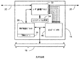
図1は、先行技術に係る再構成可能なコンピュータシステム10の一部を示す、簡略機能ブロック図である。コンピュータシステム10の構成要素のうち関連するものを挙げると、1以上のマイクロプロセッサ12、1以上のMulti−adaptive Processing(MAP(商標))素子14、および対応するシステムメモリ16がある。システムバス18は、ブリッジ22を介してマイクロプロセッサ12とMAP素子14を、クロスバースイッチ24を介してシステムメモリ16とMAP素子14を相互に接続する。さらに、同図に示す通り、各MAP素子14は隣接するMAP素子14に対する相互接続素子20を1以上有するとしてもよい。
FIG. 1 is a simplified functional block diagram illustrating a portion of a
図2は、図1のMAP素子14を詳細に示す簡略機能ブロック図である。MAP素子14の構成要素のうち関連するものを挙げると、ユーザ論理ブロック32がある。ユーザ論理ブロック32は、FPGAを備え、コンフィグレーションROM34と対応するとしてもよい。MAP制御ブロック36と対応するダイレクトメモリアクセス(DMA)エンジン38およびオンボードメモリアレイ40は、ユーザ論理ブロック32およびシステムバス18と接続されている。
FIG. 2 is a simplified functional block diagram showing in detail the
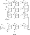
図3は、代表的なコンフィグレーションデータバス50を示す機能ブロック図である。コンフィグレーションデータバス50は、図2に示したユーザ論理ブロック32を含むFPGA全体に配設された複数のSRAMセルを備える。チップ機能をプログラムするコンフィグレーション情報は従来、図示した通りFPGA全体に配設されたSRAMセルに保持される。コンフィグレーションデータは、コンフィグレーションデータポート52を介してバイトシリアル伝送方式でロードされ、論理セル54と対応するコンフィグレーションメモリ56のアレイを順次構成していく必要がある。再構成に多大な時間がかかってしまうのは、このコンフィグレーションデータを比較的狭い、例えば8ビットのポートを用いてロードしているためである。
FIG. 3 is a functional block diagram showing a typical
図4は、本発明の実施形態に係る再構成可能なプロセッサモジュール60を示す、等角投影図法を用いて作成した簡略展開図である。再構成可能なプロセッサモジュール60は、複数の集積回路ダイ素子が積層されたハイブリッドデバイスを備える。同図に示す具体例によると、プロセッサモジュール60は、マイクロプロセッサダイ64、メモリダイ66およびFPGAダイ68が接続されたダイパッケージ62から構成される。ダイパッケージ62およびダイ64、66、68はすべて、複数の対応するコンタクトポイントまたは穴部70を全面にわたって有する。本発明の実施形態に係るプロセッサモジュール60は、マイクロプロセッサダイ64、メモリダイ66およびFPGAダイ78を自由に組み合わせてもよい。
FIG. 4 is a simplified exploded view created using isometric projection showing a reconfigurable processor module 60 according to an embodiment of the present invention. The reconfigurable processor module 60 includes a hybrid device in which a plurality of integrated circuit die elements are stacked. According to the specific example shown in the figure, the processor module 60 includes a
製造工程について、コンタクトポイント70はウェハの前面に形成され、酸化物から成る絶縁層が金属とシリコンの間に設けられる。前面の処理がすべて完了すると、ウェハの厚みを薄くして、Through−Siliconコンタクトを露出させる。Tru−Si Technologies社が開発したAtmospheric Downstream Plasma(ADP)エッチング処理を用いて、酸化物層をエッチングして金属を露出させる。このエッチング処理はシリコンの処理速度の方が速いため、シリコンはコンタクトから絶縁されたままとなる。
For the manufacturing process, the
図4に示すように、ダイ64、66および68を積層して、Through−Siliconコンタクトを設ける。このような構成とすると、キャッシュメモリダイ66は2つの役割を果たすことになる。一つには、従来と同じく高速アクセスが可能なメモリとしての機能が挙げられる。しかし上記構成によればさらに、マイクロプロセッサ64およびFPGA68が同等の速度でメモリ66にアクセスすることが可能となり、メモリ66がポートを3つ有する場合、システムの帯域幅をさらに増加させることが可能である。このような特徴によれば、従来の再構成可能なコンピュータシステムに関する多くの問題を解決することができるのは明らかである。また、メモリダイ66をほかの機能についても用いることができるようになれば、非常に大きな効果が得られると思われる。
As shown in FIG. 4, dies 64, 66 and 68 are stacked to provide a Through-Silicon contact. With such a configuration, the cache memory die 66 plays two roles. One is the function as a memory capable of high-speed access as in the past. However, the above configuration further allows the
図5は、図4の再構成可能なプロセッサモジュール60のコンフィグレーションセル80を示す機能ブロック図である。ここで、全コンフィグレーションセルを並行して更新することによって、1クロックサイクル内にFPGA70の再構成を完了させることができるとしてもよい。図3に示した従来技術とは異なり、広いコンフィグレーションデータポート82が使用され、対応するコンフィグレーションメモリ86およびバッファセル88を介して各論理セル84を更新するよう構成されている。ここで、バッファセル88はメモリダイ66(図4参照)の一部とすることが望ましい。このような構成とすることによって、論理セル84を有するFPGA68が動作中でもバッファセル88のロードが可能となる。このため、全コンフィグレーション論理セル84が並行して更新され、1クロックサイクル内でFPGA68の再構成を完了することができる。さらに、キャッシュメモリダイ66(図4参照)への接続ポイントが大幅に増えたことを生かして、FPGAダイ68上のコンフィグレーションビットストレージをすべてメモリダイ66で代わりに構成し、FPGAダイ68内で利用可能なものより大きなブロックRAM(Random Access Memory)を提供するとしてもよい。
FIG. 5 is a functional block diagram illustrating the
上記以外にも、必要な電力を削減し動作帯域幅を増加させるという利点がある。ダイ64、66および68(図4参照)間の電気経路が非常に短いので、信号レベルを低減させると同時に相互接続クロックスピードを増加させることができる。 In addition to the above, there is an advantage that the required power is reduced and the operation bandwidth is increased. Because the electrical path between the dies 64, 66 and 68 (see FIG. 4) is very short, the signal level can be reduced while the interconnect clock speed can be increased.
再構成可能なプロセッサモジュール60を組み込んだシステムの特徴としてさらに、製造途中およびモジュールのパッケージングが完了する前に、ダイパッケージ62の積層構造に含まれるマイクロプロセッサ64などのチップに試験刺激を与えることができるようにFPGA68を構成することができる。そして試験後に、所望の機能を有するようにFPGA68を再構成することができる。このため、従来のパッケージ済み部品試験システムを用いる場合に比べて、製造工程のより早い段階でより充実した試験を行うことができ、製造コストを削減することができる。
A further feature of the system incorporating the reconfigurable processor module 60 is to provide a test stimulus to a chip, such as a
再構成可能なプロセッサモジュール60が備えるFPGAダイ68の数は1つとしているが、2つ以上としてもよい。 The number of FPGA dies 68 included in the reconfigurable processor module 60 is one, but may be two or more.
セル間の接続は、現在のところ1つのダイの2次元方向に限られているが、ダイを貫通するアレイ状に配置されたコンタクト70によって、積層構造内を3次元方向に上下に結ぶことが可能になるとしてもよい。公知の積層技術ではダイの周辺に積層用コンタクトを設ける必要があるので、このような構成を実現することはできない。このような構成を持つ本発明の実施形態によれば、所定の時間内にアクセス可能なFPGAダイ68のセルの数が最高「4VT/3」(Vはウェハの伝播速度、Tは所定の伝播時間)まで増加する。
The connection between cells is currently limited to the two-dimensional direction of one die, but the inside of the stacked structure can be connected vertically in the three-dimensional direction by
上述の技術は、上記以外の種類のダイが積層構造に含まれていたり、代わりに用いられていても同様に利用できる。そのようなダイの例として、I/O用の特定用途向け集積回路(ASIC)やメモリコントローラなどが挙げられる。 The above-described technique can be used in the same manner even if dies other than those described above are included in the laminated structure or used instead. Examples of such dies include application specific integrated circuits (ASICs) for I / O and memory controllers.
本発明の実施形態に係るモジュールで用いられるダイ間接続技術は、ほかに比べて優れている。パッケージされていない構成要素を積層することは従来より可能であるが、構成要素間のI/O接続性が大幅に低くなり、I/O接続子の配設は構成要素の外周付近に限定されるため、本明細書で開示したダイ積層システムのような効果を達成できない。平面基板上に複数のダイを配設することもできるが、この方法についても、構成要素間のI/O接続が限定され領域レベルの接続が出来ないという問題がある。また、マイクロプロセッサ、メモリおよびFPGAを備える1つのダイを作成するという方法もある。このようなダイは、3つの機能素子間を接続するためにメタライゼーション層を用いており、ダイ積層方法とほぼ同じ効果を奏することができる。しかし、サイズが非常に大きくなってしまい、積層技術で用いる3つの独立したダイに比べ、生産量が大幅に少なくなる。また、積層構造を用いることによって、各ダイの作成に異なる技術を用いたり、プロセッサおよびFPGAの数や種類を任意に設定することが可能となるが、このような構成を持つ単一の大きなダイを製造するには、各組み合わせに対して複数の異なるマスクセットが必要になり、コストが非常に高くなってしまう。 The inter-die connection technology used in the module according to the embodiment of the present invention is superior to others. Stacking unpackaged components is possible in the past, but the I / O connectivity between the components is significantly reduced, and the I / O connector placement is limited to the vicinity of the component periphery. Therefore, the effect of the die stacking system disclosed in this specification cannot be achieved. Although a plurality of dies can be arranged on the flat substrate, this method also has a problem that the I / O connection between the components is limited and the connection at the region level cannot be performed. Another method is to create a single die with a microprocessor, memory and FPGA. Such a die uses a metallization layer to connect the three functional elements, and can achieve substantially the same effect as the die stacking method. However, it becomes very large in size and significantly reduces production compared to the three independent dies used in the stacking technique. Also, by using a stacked structure, it is possible to use different technologies for creating each die, and to arbitrarily set the number and type of processors and FPGAs. A single large die having such a configuration Manufacturing requires a plurality of different mask sets for each combination, resulting in a very high cost.
本発明の実施形態に係る方法によれば、間に研削などの機械的工程を挟まずに、ウェハ製造プロセスで、複数の異なる「機能素子」を積層するとしてもよい。本発明の一実施形態に係る方法を具体的に図示すると共に説明するが、この方法には数多くの変形例があり、それらの変形例によっても、請求項に記載の通り、複数の機能素子を積層し相互に接続することができる。 According to the method of the embodiment of the present invention, a plurality of different “functional elements” may be stacked in a wafer manufacturing process without interposing a mechanical process such as grinding therebetween. The method according to an embodiment of the present invention is specifically illustrated and described, but there are many variations of this method, and these variations also include a plurality of functional elements as described in the claims. They can be stacked and connected to each other.
一例を挙げると、FPGA機能素子がマイクロプロセッサ機能素子の上に積層された状態で、両機能素子間を接続することが望ましい。この順序で機能素子を積層する場合は、まずウェハに従来通りの処理を施して、図6に示すようにマイクロプロセッサを形成することから始める。ウェハ100の上面には二酸化シリコン層102と金属パッド104が配設されており、マイクロプロセッサ回路との電気接続に用いられる金属パッド104は露出している。金属パッド104は、ウェハ100の表面のどこに形成してもよい。次に、ウェハ100に第2ステップの処理が施される。
For example, it is desirable to connect the two functional elements in a state where the FPGA functional element is stacked on the microprocessor functional element. When functional elements are stacked in this order, the process is first performed on a wafer to form a microprocessor as shown in FIG. A
第2ステップでは、通常のリソグラフィーとウェハ製造プロセスを用いて、金属コンタクト104以外をマスクするとともに酸化物層の上にシリコンから成るエピタキシャル層を成長させる。図7に示した二酸化シリコン層102は、金属コンタクト104以外をマスクしてから形成されたものである。図8に、二酸化シリコン層上に成長させたエピタキシャル層106を示す。エピタキシャル層106は、酸化物層102上に成長するため、本質的には多結晶性を有する。現在では、通常のポリシリコン処理技術を用いて、このエピタキシャル層106にポリシリコントランジスタから成るFPGA機能素子を製造することが可能である。この処理によって、図9に示すように、FPGAの金属相互接続子108をマイクロプロセッサの金属パッドのうち少なくとも1つと電気的に接続する。具体的には、ポリシリコンから成るエピタキシャル層106とその下の二酸化シリコン層102にエッチングを施して、機能素子同士を相互接続する必要がある箇所に対応させて、両層を貫通するビアを形成し、該ビア内に相互接続子を形成する。このようにして、マイクロプロセッサとFPGAが物理的に接続され、本発明の実施形態に係る積層型プロセッサが形成される。FPGAに関連した工程がすべて完了すると、図10に示すように、最上面は二酸化シリコン層110と露出した金属パッド108で構成される。この金属パッド108は、通常の集積回路パッケージング技術を用いて、パッケージボンディングワイヤまたはフリップチップ用ハンダとの接続を行うこともできる。
In the second step, an epitaxial layer made of silicon is grown on the oxide layer while masking other than the
または、金属パッド108以外にマスクを施し、その上にさらにエピタキシャル層を形成して、第3の機能素子を形成するとしてもよい。第3の機能素子は、例えばI/Oコントローラ、メモリ、FPGAまたはマイクロプロセッサなどで、既に形成した2つの機能素子と一体化するように設けられる。図11に、1つのベースウェハ上に3つの機能素子が形成されたモジュールを示す。このモジュールは、酸化物層102および110が間に設けられた機能素子100、106、112を備える。同図には、最上面に設けられた酸化物層114および3つの機能素子すべてを相互接続する金属パッド108も示す。
Alternatively, a third functional element may be formed by applying a mask to a portion other than the
集積回路ダイ素子および特定の用途向けの構成を具体的に挙げて本発明の内容を説明したが、上記の説明は例示にすぎず本発明の範囲を限定するものではない。特に、当業者であれば上記の教示内容に基づきさまざまな変形例を得ることができるのは明らかである。そのような変形例は、既に公知となっている特徴や本明細書で開示した特徴と共にまたはそのような特徴に代わって用いることができるものを含むとしてもよい。本出願の請求項には特徴の組み合わせを具体的に記載したが、本明細書の開示範囲には、本出願の請求項にかかる発明に関係していてもいなくても、また本発明が解決に取り組む技術上の問題の解決方法に関係しようとしまいと、当業者には明らかである、直接的または間接的に開示された新規性を有する特徴または新規性を有する特徴の組み合わせ、またはそれを一般化したものまたはその変形例が含まれる。出願人は、このような特徴および/または特徴の組み合わせに関して、本出願または派生する出願の審査過程において、新規の請求項を作成する権利を有するものである。 While the contents of the invention have been described with specific reference to integrated circuit die elements and configurations for specific applications, the above description is illustrative only and is not intended to limit the scope of the invention. It will be apparent to those skilled in the art that various modifications can be obtained based on the above teachings. Such variations may include features that are already known or can be used in conjunction with or in place of features disclosed herein. Although combinations of features are specifically described in the claims of the present application, the disclosure scope of the present specification does not relate to the invention according to the claims of the present application, and Any feature or novel combination of novelty disclosed directly or indirectly that would be apparent to one of ordinary skill in the art, regardless of how the technical problem addressed Generalizations or variations thereof are included. Applicants have the right to create new claims for such features and / or combinations of features during the examination process of this or derived applications.
Claims (60)
プログラム可能なアレイを有する、少なくとも1つの第1集積回路機能素子、
前記第1集積回路機能素子の前記プログラム可能なアレイに積層され且つ電気的に接続された、少なくとも1つの第2集積回路機能素子
を備えるプロセッサモジュール。 A processor module,
At least one first integrated circuit functional element having a programmable array;
A processor module comprising at least one second integrated circuit functional element stacked and electrically connected to the programmable array of first integrated circuit functional elements.
請求項1に記載のプロセッサモジュール。 The processor module of claim 1, wherein the programmable array of first integrated circuit functional elements comprises a field programmable gate array (FPGA).
請求項1に記載のプロセッサモジュール。 The processor module according to claim 1, wherein the processor of the second integrated circuit functional element includes a microprocessor.
請求項1に記載のプロセッサモジュール。 The processor module according to claim 1, wherein the second integrated circuit functional element includes a memory.
をさらに備える請求項1に記載のプロセッサモジュール。 2. The processor module according to claim 1, further comprising at least one third integrated circuit functional element stacked and electrically connected to at least one of the first integrated circuit functional element and the second integrated circuit functional element. .
請求項5に記載のプロセッサモジュール。 The processor module according to claim 5, wherein the third integrated circuit functional element includes a memory.
請求項1に記載のプロセッサモジュール。 The processor module of claim 1, wherein the programmable array is reconfigurable as a processor element (PE).
請求項1に記載のプロセッサモジュール。 2. The processor module according to claim 1, wherein the first integrated circuit functional element and the second integrated circuit functional element are electrically connected by a plurality of contact points arranged on the entire surface of both functional elements.
プロセッサ、
メモリ、
少なくとも1つのプロセッサモジュールであって、プログラム可能なアレイを含む少なくとも1つの第1集積回路機能素子および前記第1集積回路機能素子の前記プログラム可能なアレイに積層され且つ電気的に接続された少なくとも1つの第2集積回路機能素子を有するプロセッサモジュール
を備えるコンピュータシステム。 A reconfigurable computer system comprising:
Processor,
memory,
At least one processor module comprising at least one first integrated circuit functional element including a programmable array and at least one stacked and electrically connected to the programmable array of the first integrated circuit functional elements; A computer system comprising a processor module having two second integrated circuit functional elements.
請求項9に記載のコンピュータシステム。 The computer system of claim 9, wherein the programmable array of first integrated circuit functional elements comprises an FPGA.
請求項9に記載のコンピュータシステム。 The computer system according to claim 9, wherein the processor of the second integrated circuit functional element includes a microprocessor.
請求項9に記載のコンピュータシステム。 The computer system according to claim 9, wherein the second integrated circuit functional element includes a memory.
をさらに備える請求項9に記載のコンピュータシステム。 The computer system according to claim 9, further comprising at least one third integrated circuit functional element stacked and electrically connected to at least one of the first integrated circuit functional element and the second integrated circuit functional element. .
請求項13に記載のコンピュータシステム。 The computer system according to claim 13, wherein the third integrated circuit functional element includes a memory.
請求項9に記載のコンピュータシステム。 The computer system of claim 9, wherein the programmable array is reconfigurable as a processor element (PE).
プログラム可能なアレイを有する、少なくとも1つの第1集積回路機能素子、
前記第1集積回路機能素子の前記プログラム可能なアレイに積層され且つ電気的に接続されたプロセッサを有する、少なくとも1つの第2集積回路機能素子、
前記第1集積回路機能素子の前記プログラム可能なアレイおよび前記第2集積回路機能素子のプロセッサに積層され且つ電気的に接続されたメモリを有する、少なくとも1つの第3集積回路機能素子
を備えるプロセッサモジュール。 A processor module,
At least one first integrated circuit functional element having a programmable array;
At least one second integrated circuit functional element having a processor stacked and electrically connected to the programmable array of the first integrated circuit functional elements;
A processor module comprising at least one third integrated circuit functional element having a memory stacked and electrically connected to the programmable array of first integrated circuit functional elements and a processor of the second integrated circuit functional element .
請求項16に記載のプロセッサモジュール。 The processor module of claim 16, wherein the programmable array of first integrated circuit functional elements comprises an FPGA.
請求項16に記載のプロセッサモジュール。 The processor module according to claim 16, wherein the processor of the second integrated circuit functional element includes a microprocessor.
請求項16に記載のプロセッサモジュール。 The processor module according to claim 16, wherein the memory of the third integrated circuit functional element includes a memory array.
請求項16に記載のプロセッサモジュール。 The processor module of claim 16, wherein the programmable array is reconfigurable as a processor element (PE).
請求項16に記載のプロセッサモジュール。 The first integrated circuit functional element, the second integrated circuit functional element, and the third integrated circuit functional element are electrically connected by a plurality of contact points arranged on the entire surface of the three functional elements. Item 17. The processor module according to Item 16.
FPGAを有する、少なくとも1つの第1集積回路機能素子、
前記第1集積回路機能素子の前記FPGAに積層され且つ電気的に接続されたメモリアレイを有する、少なくとも1つの第2集積回路機能素子
を備えるプログラム可能アレイモジュール。 A programmable array module,
At least one first integrated circuit functional element having an FPGA;
A programmable array module comprising at least one second integrated circuit functional element having a memory array stacked and electrically connected to the FPGA of the first integrated circuit functional element.
請求項22に記載のプログラム可能アレイモジュール。 The programmable array module according to claim 22, wherein the FPGA is programmable as a processor element (PE).
請求項23に記載のプログラム可能アレイモジュール。 The programmable array module of claim 23, wherein the memory array accelerates reconfiguration of the FPGA into a processor element (PE).
請求項23に記載のプログラム可能アレイモジュール。 The programmable array module according to claim 23, wherein the memory array accelerates a reference operation to the processor element (PE) by an external memory.
請求項23に記載のプログラム可能アレイモジュール。 The programmable array module according to claim 23, wherein the memory array functions as a block memory for the processor element (PE).
プログラム可能なアレイを有する、少なくとも1つの第1集積回路機能素子、
前記第1集積回路機能素子の前記プログラム可能なアレイに積層され且つ電気的に接続されたプロセッサを有する、少なくとも1つの第2集積回路機能素子、
前記第1集積回路機能素子の前記プログラム可能なアレイおよび前記第2集積回路機能素子のプロセッサに積層され且つ電気的に接続されたメモリを有する、少なくとも1つの第3集積回路機能素子
を備え、
前記プロセッサおよび前記プログラム可能なアレイは、両者間でデータを共有する
再構成可能なプロセッサモジュール。 A reconfigurable processor module comprising:
At least one first integrated circuit functional element having a programmable array;
At least one second integrated circuit functional element having a processor stacked and electrically connected to the programmable array of the first integrated circuit functional elements;
At least one third integrated circuit functional element having a memory stacked and electrically connected to the programmable array of the first integrated circuit functional elements and a processor of the second integrated circuit functional element;
The processor and the programmable array are reconfigurable processor modules that share data between them.
請求項27に記載の再構成可能なプロセッサモジュール。 The reconfigurable processor module according to claim 27, wherein the memory stores the data at least temporarily.
請求項27に記載の再構成可能なプロセッサモジュール。 28. The reconfigurable processor module of claim 27, wherein the programmable array of first integrated circuit functional elements includes an FPGA.
請求項27に記載の再構成可能なプロセッサモジュール。 The reconfigurable processor module according to claim 27, wherein the processor of the second integrated circuit functional element includes a microprocessor.
請求項27に記載の再構成可能なプロセッサモジュール。 28. The reconfigurable processor module of claim 27, wherein the memory of the third integrated circuit functional element includes a memory array.
FPGAを有する、少なくとも1つの第1集積回路機能素子、
前記第1集積回路機能素子の前記FPGAに積層され且つ電気的に接続されたメモリアレイを有する、少なくとも1つの第2集積回路機能素子
を備え、
前記第1集積回路機能素子および前記第2集積回路機能素子は、両機能素子の表面全体に配された複数のコンタクトポイントによって電気的に接続されている
プログラム可能アレイモジュール。 A programmable array module,
At least one first integrated circuit functional element having an FPGA;
At least one second integrated circuit functional element having a memory array stacked and electrically connected to the FPGA of the first integrated circuit functional element;
The programmable integrated circuit module wherein the first integrated circuit functional element and the second integrated circuit functional element are electrically connected by a plurality of contact points disposed on the entire surface of both functional elements.
請求項32に記載のプログラム可能アレイモジュール。 The programmable array module of claim 32, wherein the FPGA is programmable as a processor element (PE).
請求項33に記載のプログラム可能アレイモジュール。 The programmable array module of claim 33, wherein the memory array accelerates reconfiguration of the FPGA into a processor element (PE).
請求項33に記載のプログラム可能アレイモジュール。 The programmable array module according to claim 33, wherein the memory array accelerates a reference operation to the processor element (PE) by an external memory.
請求項33に記載のプログラム可能アレイモジュール。 The programmable array module according to claim 33, wherein the memory array functions as a block memory for the processor element (PE).
請求項32に記載のプログラム可能アレイモジュール。 The programmable array module according to claim 32, wherein a test stimulus is applied from the FPGA to the second integrated circuit functional element via the contact point.
をさらに備える請求項32に記載のプログラム可能アレイモジュール。 33. The programmable device of claim 32, further comprising at least one third integrated circuit functional element stacked and electrically connected to at least one of the first integrated circuit functional element and the second integrated circuit functional element. Array module.
請求項38に記載のプログラム可能アレイモジュール。 40. The programmable array module of claim 38, wherein the third integrated circuit functional element comprises an FPGA.
請求項38に記載のプログラム可能アレイモジュール。 40. The programmable array module of claim 38, wherein the third integrated circuit functional element comprises an input / output (I / O) controller.
ベースウェハ上に、FPGAおよび複数の金属パッドを有する少なくとも1つの第1集積回路機能素子を形成すること、
前記第1集積回路機能素子の上に、第1エピタキシャル層を形成すること、
前記第1エピタキシャル層に、メモリアレイを有する少なくとも1つの第2集積回路機能素子を形成すること
を備え、
前記第2集積回路機能素子は複数の金属パッドを有し、前記複数の金属パッドのうち少なくとも1つは前記第1集積回路機能素子の前記金属パッドと電気的に接続されている
方法。 A method of manufacturing a programmable array module comprising:
Forming at least one first integrated circuit functional element having an FPGA and a plurality of metal pads on a base wafer;
Forming a first epitaxial layer on the first integrated circuit functional element;
Forming at least one second integrated circuit functional element having a memory array in the first epitaxial layer;
The second integrated circuit functional element has a plurality of metal pads, and at least one of the plurality of metal pads is electrically connected to the metal pads of the first integrated circuit functional element.
をさらに備える請求項41に記載の方法。 The method of claim 41, further comprising: forming a first silicon dioxide layer on a surface of the first integrated circuit functional element.
をさらに備える請求項42に記載の方法。 43. The method of claim 42, further comprising: forming the first epitaxial layer on a surface of the first silicon dioxide layer.
請求項41に記載の方法。 42. The method of claim 41, wherein forming the first epitaxial layer includes forming a polysilicon layer.
をさらに備える請求項41に記載の方法。 Etching the first epitaxial layer so that an interconnector is formed between the metal pad of the first integrated circuit functional element and the metal pad of the second integrated circuit functional element. 42. The method of claim 41, further comprising:
をさらに備える請求項45に記載の方法。 The method according to claim 45, further comprising: etching through the first silicon dioxide layer formed on the surface of the first integrated circuit functional element.
をさらに備える請求項41に記載の方法。 42. The method according to claim 41, further comprising: forming a second epitaxial layer on the first epitaxial layer such that a third functional element is formed integrally with the first functional element and the second functional element. The method described.
請求項47に記載の方法。 48. The method of claim 47, wherein forming the third functional element includes forming an I / O controller, memory, FPGA or microprocessor.
をさらに備える請求項47に記載の方法。 48. The method of claim 47, further comprising forming a second silicon dioxide layer on a surface of the second epitaxial layer.
請求項47に記載の方法。 48. The method of claim 47, wherein forming the second epitaxial layer includes forming a polysilicon layer.
ベースウェハ上に、マイクロプロセッサなどである第1集積回路機能素子を少なくとも1つ形成すること、
ウェハ製造プロセスを用いて、前記第1集積回路機能素子上に、FPGAなどの第2集積回路機能素子を少なくとも1つ形成すること
を備える方法。 A method of manufacturing a processor module, comprising:
Forming at least one first integrated circuit functional element such as a microprocessor on a base wafer;
Forming at least one second integrated circuit functional element such as an FPGA on the first integrated circuit functional element using a wafer manufacturing process.
をさらに備える請求項51に記載の方法。 Electrically connecting at least one of a plurality of metal pads corresponding to the first integrated circuit functional element and at least one of a plurality of metal pads corresponding to the second integrated circuit functional element. Item 52. The method according to Item 51.
請求項51に記載の方法。 52. The method of claim 51, wherein forming the second integrated circuit functional element includes forming an epitaxial layer.
請求項53に記載の方法。 54. The method of claim 53, wherein forming the epitaxial layer includes forming a polysilicon layer.
をさらに備える請求項51に記載の方法。 52. The method of claim 51, further comprising forming a silicon dioxide layer on the top surface of the first integrated circuit functional element.
をさらに備える請求項51に記載の方法。 52. The method according to claim 51, further comprising: etching the second integrated circuit functional element so as to penetrate therethrough so as to electrically connect the first integrated circuit functional element and the second integrated circuit functional element. the method of.
をさらに備える請求項51に記載の方法。 52. The method of claim 51, further comprising forming a third functional element integrated with the first integrated circuit functional element and the second integrated circuit functional element using a wafer manufacturing process.
請求項57に記載の方法。 58. The method according to claim 57, wherein forming the third functional element includes forming an epitaxial layer.
請求項58に記載の方法。 59. The method of claim 58, wherein forming the epitaxial layer includes forming a polysilicon layer.
請求項57に記載の方法。 58. The method of claim 57, wherein forming the third functional element includes forming an I / O controller, memory, FPGA or microprocessor.
Applications Claiming Priority (2)
| Application Number | Priority Date | Filing Date | Title |
|---|---|---|---|
| US10/802,067 US7126214B2 (en) | 2001-12-05 | 2004-03-16 | Reconfigurable processor module comprising hybrid stacked integrated circuit die elements |
| PCT/US2004/041791 WO2005094240A2 (en) | 2004-03-16 | 2004-12-14 | Reconfigurable processor module with stacked die elements |
Publications (2)
| Publication Number | Publication Date |
|---|---|
| JP2007529894A true JP2007529894A (en) | 2007-10-25 |
| JP2007529894A5 JP2007529894A5 (en) | 2008-01-31 |
Family
ID=35064225
Family Applications (1)
| Application Number | Title | Priority Date | Filing Date |
|---|---|---|---|
| JP2007503893A Pending JP2007529894A (en) | 2004-03-16 | 2004-12-14 | Reconfigurable processor module with stacked die elements |
Country Status (4)
| Country | Link |
|---|---|
| US (2) | US7126214B2 (en) |
| EP (1) | EP1726042A4 (en) |
| JP (1) | JP2007529894A (en) |
| WO (1) | WO2005094240A2 (en) |
Cited By (4)
| Publication number | Priority date | Publication date | Assignee | Title |
|---|---|---|---|---|
| JP2010080870A (en) * | 2008-09-29 | 2010-04-08 | National Institute Of Advanced Industrial Science & Technology | Reconfigurable integrated circuit |
| JP2013546275A (en) * | 2010-11-17 | 2013-12-26 | ザイリンクス インコーポレイテッド | Multichip module for communication |
| JP2015039155A (en) * | 2013-08-19 | 2015-02-26 | 富士通株式会社 | Control method, arithmetic device and control program |
| JP2016529702A (en) * | 2013-07-16 | 2016-09-23 | クゥアルコム・インコーポレイテッドQualcomm Incorporated | Complete system-on-chip (SOC) using monolithic three-dimensional (3D) integrated circuit (IC) (3DIC) technology |
Families Citing this family (296)
| Publication number | Priority date | Publication date | Assignee | Title |
|---|---|---|---|---|
| US6627985B2 (en) * | 2001-12-05 | 2003-09-30 | Arbor Company Llp | Reconfigurable processor module comprising hybrid stacked integrated circuit die elements |
| US20040004251A1 (en) * | 2002-07-08 | 2004-01-08 | Madurawe Raminda U. | Insulated-gate field-effect thin film transistors |
| US6992503B2 (en) | 2002-07-08 | 2006-01-31 | Viciciv Technology | Programmable devices with convertibility to customizable devices |
| US7112994B2 (en) * | 2002-07-08 | 2006-09-26 | Viciciv Technology | Three dimensional integrated circuits |
| US7673273B2 (en) | 2002-07-08 | 2010-03-02 | Tier Logic, Inc. | MPGA products based on a prototype FPGA |
| US7129744B2 (en) * | 2003-10-23 | 2006-10-31 | Viciciv Technology | Programmable interconnect structures |
| US6855988B2 (en) * | 2002-07-08 | 2005-02-15 | Viciciv Technology | Semiconductor switching devices |
| WO2004021643A1 (en) * | 2002-08-29 | 2004-03-11 | Bae Systems Information And Electronic Systems Integration Inc. | Reconfigurable compute engine interconnect fabric |
| US8643162B2 (en) | 2007-11-19 | 2014-02-04 | Raminda Udaya Madurawe | Pads and pin-outs in three dimensional integrated circuits |
| US7812458B2 (en) * | 2007-11-19 | 2010-10-12 | Tier Logic, Inc. | Pad invariant FPGA and ASIC devices |
| US8084866B2 (en) * | 2003-12-10 | 2011-12-27 | Micron Technology, Inc. | Microelectronic devices and methods for filling vias in microelectronic devices |
| US7030651B2 (en) | 2003-12-04 | 2006-04-18 | Viciciv Technology | Programmable structured arrays |
| US7622951B2 (en) * | 2004-02-14 | 2009-11-24 | Tabula, Inc. | Via programmable gate array with offset direct connections |
| US7126381B1 (en) | 2004-02-14 | 2006-10-24 | Herman Schmit | VPA interconnect circuit |
| US7489164B2 (en) * | 2004-05-17 | 2009-02-10 | Raminda Udaya Madurawe | Multi-port memory devices |
| US7083425B2 (en) | 2004-08-27 | 2006-08-01 | Micron Technology, Inc. | Slanted vias for electrical circuits on circuit boards and other substrates |
| US7301242B2 (en) | 2004-11-04 | 2007-11-27 | Tabula, Inc. | Programmable system in package |
| US7530044B2 (en) | 2004-11-04 | 2009-05-05 | Tabula, Inc. | Method for manufacturing a programmable system in package |
| US8201124B1 (en) | 2005-03-15 | 2012-06-12 | Tabula, Inc. | System in package and method of creating system in package |
| US7795134B2 (en) | 2005-06-28 | 2010-09-14 | Micron Technology, Inc. | Conductive interconnect structures and formation methods using supercritical fluids |
| US7863187B2 (en) | 2005-09-01 | 2011-01-04 | Micron Technology, Inc. | Microfeature workpieces and methods for forming interconnects in microfeature workpieces |
| US7262134B2 (en) | 2005-09-01 | 2007-08-28 | Micron Technology, Inc. | Microfeature workpieces and methods for forming interconnects in microfeature workpieces |
| US20070045120A1 (en) * | 2005-09-01 | 2007-03-01 | Micron Technology, Inc. | Methods and apparatus for filling features in microfeature workpieces |
| KR100713121B1 (en) * | 2005-09-27 | 2007-05-02 | 한국전자통신연구원 | Chip and a chip stack using the same and a method for manufacturing the same |
| US7262633B1 (en) * | 2005-11-11 | 2007-08-28 | Tabula, Inc. | Via programmable gate array with offset bit lines |
| KR100662873B1 (en) * | 2006-01-03 | 2007-01-02 | 삼성전자주식회사 | Loop accelerator and processing system for data having it |
| US7486111B2 (en) * | 2006-03-08 | 2009-02-03 | Tier Logic, Inc. | Programmable logic devices comprising time multiplexed programmable interconnect |
| US20070290333A1 (en) * | 2006-06-16 | 2007-12-20 | Intel Corporation | Chip stack with a higher power chip on the outside of the stack |
| US20080024165A1 (en) * | 2006-07-28 | 2008-01-31 | Raminda Udaya Madurawe | Configurable embedded multi-port memory |
| US7629249B2 (en) | 2006-08-28 | 2009-12-08 | Micron Technology, Inc. | Microfeature workpieces having conductive interconnect structures formed by chemically reactive processes, and associated systems and methods |
| US7902643B2 (en) * | 2006-08-31 | 2011-03-08 | Micron Technology, Inc. | Microfeature workpieces having interconnects and conductive backplanes, and associated systems and methods |
| KR20080046892A (en) * | 2006-11-23 | 2008-05-28 | 삼성전자주식회사 | Liquid crystal display device and manufacturing method of the same |
| SG150410A1 (en) * | 2007-08-31 | 2009-03-30 | Micron Technology Inc | Partitioned through-layer via and associated systems and methods |
| US7692448B2 (en) * | 2007-09-12 | 2010-04-06 | Neal Solomon | Reprogrammable three dimensional field programmable gate arrays |
| US7635988B2 (en) * | 2007-11-19 | 2009-12-22 | Tier Logic, Inc. | Multi-port thin-film memory devices |
| WO2009139768A1 (en) * | 2008-05-13 | 2009-11-19 | Viciciv Technology, Inc. | Three dimensional programmable devices |
| US20090128189A1 (en) * | 2007-11-19 | 2009-05-21 | Raminda Udaya Madurawe | Three dimensional programmable devices |
| US7884015B2 (en) | 2007-12-06 | 2011-02-08 | Micron Technology, Inc. | Methods for forming interconnects in microelectronic workpieces and microelectronic workpieces formed using such methods |
| US7573293B2 (en) * | 2007-12-26 | 2009-08-11 | Tier Logic, Inc. | Programmable logic based latches and shift registers |
| US7573294B2 (en) * | 2007-12-26 | 2009-08-11 | Tier Logic, Inc. | Programmable logic based latches and shift registers |
| US7602213B2 (en) | 2007-12-26 | 2009-10-13 | Tier Logic, Inc. | Using programmable latch to implement logic |
| US7800238B2 (en) | 2008-06-27 | 2010-09-21 | Micron Technology, Inc. | Surface depressions for die-to-die interconnects and associated systems and methods |
| US8230375B2 (en) | 2008-09-14 | 2012-07-24 | Raminda Udaya Madurawe | Automated metal pattern generation for integrated circuits |
| US20100123477A1 (en) * | 2008-11-20 | 2010-05-20 | Shih-Wei Sun | Programmable array module |
| US9509313B2 (en) | 2009-04-14 | 2016-11-29 | Monolithic 3D Inc. | 3D semiconductor device |
| US8669778B1 (en) | 2009-04-14 | 2014-03-11 | Monolithic 3D Inc. | Method for design and manufacturing of a 3D semiconductor device |
| US8378715B2 (en) | 2009-04-14 | 2013-02-19 | Monolithic 3D Inc. | Method to construct systems |
| US8427200B2 (en) | 2009-04-14 | 2013-04-23 | Monolithic 3D Inc. | 3D semiconductor device |
| US8405420B2 (en) | 2009-04-14 | 2013-03-26 | Monolithic 3D Inc. | System comprising a semiconductor device and structure |
| US8058137B1 (en) | 2009-04-14 | 2011-11-15 | Monolithic 3D Inc. | Method for fabrication of a semiconductor device and structure |
| US8395191B2 (en) | 2009-10-12 | 2013-03-12 | Monolithic 3D Inc. | Semiconductor device and structure |
| US7986042B2 (en) | 2009-04-14 | 2011-07-26 | Monolithic 3D Inc. | Method for fabrication of a semiconductor device and structure |
| US8373439B2 (en) | 2009-04-14 | 2013-02-12 | Monolithic 3D Inc. | 3D semiconductor device |
| US9577642B2 (en) | 2009-04-14 | 2017-02-21 | Monolithic 3D Inc. | Method to form a 3D semiconductor device |
| US8754533B2 (en) | 2009-04-14 | 2014-06-17 | Monolithic 3D Inc. | Monolithic three-dimensional semiconductor device and structure |
| US8362800B2 (en) | 2010-10-13 | 2013-01-29 | Monolithic 3D Inc. | 3D semiconductor device including field repairable logics |
| US8258810B2 (en) | 2010-09-30 | 2012-09-04 | Monolithic 3D Inc. | 3D semiconductor device |
| US8115511B2 (en) * | 2009-04-14 | 2012-02-14 | Monolithic 3D Inc. | Method for fabrication of a semiconductor device and structure |
| US9711407B2 (en) | 2009-04-14 | 2017-07-18 | Monolithic 3D Inc. | Method of manufacturing a three dimensional integrated circuit by transfer of a mono-crystalline layer |
| US8384426B2 (en) | 2009-04-14 | 2013-02-26 | Monolithic 3D Inc. | Semiconductor device and structure |
| US8362482B2 (en) | 2009-04-14 | 2013-01-29 | Monolithic 3D Inc. | Semiconductor device and structure |
| US8581349B1 (en) | 2011-05-02 | 2013-11-12 | Monolithic 3D Inc. | 3D memory semiconductor device and structure |
| US10043781B2 (en) | 2009-10-12 | 2018-08-07 | Monolithic 3D Inc. | 3D semiconductor device and structure |
| US8536023B2 (en) | 2010-11-22 | 2013-09-17 | Monolithic 3D Inc. | Method of manufacturing a semiconductor device and structure |
| US10910364B2 (en) | 2009-10-12 | 2021-02-02 | Monolitaic 3D Inc. | 3D semiconductor device |
| US9099424B1 (en) | 2012-08-10 | 2015-08-04 | Monolithic 3D Inc. | Semiconductor system, device and structure with heat removal |
| US8742476B1 (en) | 2012-11-27 | 2014-06-03 | Monolithic 3D Inc. | Semiconductor device and structure |
| US10388863B2 (en) | 2009-10-12 | 2019-08-20 | Monolithic 3D Inc. | 3D memory device and structure |
| US8450804B2 (en) | 2011-03-06 | 2013-05-28 | Monolithic 3D Inc. | Semiconductor device and structure for heat removal |
| US8294159B2 (en) | 2009-10-12 | 2012-10-23 | Monolithic 3D Inc. | Method for fabrication of a semiconductor device and structure |
| US10354995B2 (en) | 2009-10-12 | 2019-07-16 | Monolithic 3D Inc. | Semiconductor memory device and structure |
| US10366970B2 (en) | 2009-10-12 | 2019-07-30 | Monolithic 3D Inc. | 3D semiconductor device and structure |
| US8476145B2 (en) | 2010-10-13 | 2013-07-02 | Monolithic 3D Inc. | Method of fabricating a semiconductor device and structure |
| US10157909B2 (en) | 2009-10-12 | 2018-12-18 | Monolithic 3D Inc. | 3D semiconductor device and structure |
| US11018133B2 (en) | 2009-10-12 | 2021-05-25 | Monolithic 3D Inc. | 3D integrated circuit |
| US11374118B2 (en) | 2009-10-12 | 2022-06-28 | Monolithic 3D Inc. | Method to form a 3D integrated circuit |
| US8159060B2 (en) | 2009-10-29 | 2012-04-17 | International Business Machines Corporation | Hybrid bonding interface for 3-dimensional chip integration |
| US8386690B2 (en) * | 2009-11-13 | 2013-02-26 | International Business Machines Corporation | On-chip networks for flexible three-dimensional chip integration |
| US8373230B1 (en) | 2010-10-13 | 2013-02-12 | Monolithic 3D Inc. | Method for fabrication of a semiconductor device and structure |
| US8461035B1 (en) | 2010-09-30 | 2013-06-11 | Monolithic 3D Inc. | Method for fabrication of a semiconductor device and structure |
| US8026521B1 (en) | 2010-10-11 | 2011-09-27 | Monolithic 3D Inc. | Semiconductor device and structure |
| US8492886B2 (en) | 2010-02-16 | 2013-07-23 | Monolithic 3D Inc | 3D integrated circuit with logic |
| US9099526B2 (en) | 2010-02-16 | 2015-08-04 | Monolithic 3D Inc. | Integrated circuit device and structure |
| US8541819B1 (en) | 2010-12-09 | 2013-09-24 | Monolithic 3D Inc. | Semiconductor device and structure |
| US8298875B1 (en) | 2011-03-06 | 2012-10-30 | Monolithic 3D Inc. | Method for fabrication of a semiconductor device and structure |
| US8809158B2 (en) * | 2010-03-12 | 2014-08-19 | Hewlett-Packard Development Company, L.P. | Device having memristive memory |
| US9219005B2 (en) | 2011-06-28 | 2015-12-22 | Monolithic 3D Inc. | Semiconductor system and device |
| US10217667B2 (en) | 2011-06-28 | 2019-02-26 | Monolithic 3D Inc. | 3D semiconductor device, fabrication method and system |
| US9953925B2 (en) | 2011-06-28 | 2018-04-24 | Monolithic 3D Inc. | Semiconductor system and device |
| US8642416B2 (en) | 2010-07-30 | 2014-02-04 | Monolithic 3D Inc. | Method of forming three dimensional integrated circuit devices using layer transfer technique |
| US8901613B2 (en) | 2011-03-06 | 2014-12-02 | Monolithic 3D Inc. | Semiconductor device and structure for heat removal |
| US8163581B1 (en) | 2010-10-13 | 2012-04-24 | Monolith IC 3D | Semiconductor and optoelectronic devices |
| US11482440B2 (en) | 2010-12-16 | 2022-10-25 | Monolithic 3D Inc. | 3D semiconductor device and structure with a built-in test circuit for repairing faulty circuits |
| US10497713B2 (en) | 2010-11-18 | 2019-12-03 | Monolithic 3D Inc. | 3D semiconductor memory device and structure |
| US8273610B2 (en) | 2010-11-18 | 2012-09-25 | Monolithic 3D Inc. | Method of constructing a semiconductor device and structure |
| US11315980B1 (en) | 2010-10-11 | 2022-04-26 | Monolithic 3D Inc. | 3D semiconductor device and structure with transistors |
| US10290682B2 (en) | 2010-10-11 | 2019-05-14 | Monolithic 3D Inc. | 3D IC semiconductor device and structure with stacked memory |
| US11469271B2 (en) | 2010-10-11 | 2022-10-11 | Monolithic 3D Inc. | Method to produce 3D semiconductor devices and structures with memory |
| US10896931B1 (en) | 2010-10-11 | 2021-01-19 | Monolithic 3D Inc. | 3D semiconductor device and structure |
| US11257867B1 (en) | 2010-10-11 | 2022-02-22 | Monolithic 3D Inc. | 3D semiconductor device and structure with oxide bonds |
| US8114757B1 (en) | 2010-10-11 | 2012-02-14 | Monolithic 3D Inc. | Semiconductor device and structure |
| US11018191B1 (en) | 2010-10-11 | 2021-05-25 | Monolithic 3D Inc. | 3D semiconductor device and structure |
| US11158674B2 (en) | 2010-10-11 | 2021-10-26 | Monolithic 3D Inc. | Method to produce a 3D semiconductor device and structure |
| US11024673B1 (en) | 2010-10-11 | 2021-06-01 | Monolithic 3D Inc. | 3D semiconductor device and structure |
| US11600667B1 (en) | 2010-10-11 | 2023-03-07 | Monolithic 3D Inc. | Method to produce 3D semiconductor devices and structures with memory |
| US11227897B2 (en) | 2010-10-11 | 2022-01-18 | Monolithic 3D Inc. | Method for producing a 3D semiconductor memory device and structure |
| US10833108B2 (en) | 2010-10-13 | 2020-11-10 | Monolithic 3D Inc. | 3D microdisplay device and structure |
| US11437368B2 (en) | 2010-10-13 | 2022-09-06 | Monolithic 3D Inc. | Multilevel semiconductor device and structure with oxide bonding |
| US11929372B2 (en) | 2010-10-13 | 2024-03-12 | Monolithic 3D Inc. | Multilevel semiconductor device and structure with image sensors and wafer bonding |
| US11063071B1 (en) | 2010-10-13 | 2021-07-13 | Monolithic 3D Inc. | Multilevel semiconductor device and structure with waveguides |
| US11855100B2 (en) | 2010-10-13 | 2023-12-26 | Monolithic 3D Inc. | Multilevel semiconductor device and structure with oxide bonding |
| US10978501B1 (en) | 2010-10-13 | 2021-04-13 | Monolithic 3D Inc. | Multilevel semiconductor device and structure with waveguides |
| US11869915B2 (en) | 2010-10-13 | 2024-01-09 | Monolithic 3D Inc. | Multilevel semiconductor device and structure with image sensors and wafer bonding |
| US11164898B2 (en) | 2010-10-13 | 2021-11-02 | Monolithic 3D Inc. | Multilevel semiconductor device and structure |
| US11043523B1 (en) | 2010-10-13 | 2021-06-22 | Monolithic 3D Inc. | Multilevel semiconductor device and structure with image sensors |
| US11163112B2 (en) | 2010-10-13 | 2021-11-02 | Monolithic 3D Inc. | Multilevel semiconductor device and structure with electromagnetic modulators |
| US11133344B2 (en) | 2010-10-13 | 2021-09-28 | Monolithic 3D Inc. | Multilevel semiconductor device and structure with image sensors |
| US9197804B1 (en) | 2011-10-14 | 2015-11-24 | Monolithic 3D Inc. | Semiconductor and optoelectronic devices |
| US11404466B2 (en) | 2010-10-13 | 2022-08-02 | Monolithic 3D Inc. | Multilevel semiconductor device and structure with image sensors |
| US11327227B2 (en) | 2010-10-13 | 2022-05-10 | Monolithic 3D Inc. | Multilevel semiconductor device and structure with electromagnetic modulators |
| US11694922B2 (en) | 2010-10-13 | 2023-07-04 | Monolithic 3D Inc. | Multilevel semiconductor device and structure with oxide bonding |
| US11855114B2 (en) | 2010-10-13 | 2023-12-26 | Monolithic 3D Inc. | Multilevel semiconductor device and structure with image sensors and wafer bonding |
| US8379458B1 (en) | 2010-10-13 | 2013-02-19 | Monolithic 3D Inc. | Semiconductor device and structure |
| US10679977B2 (en) | 2010-10-13 | 2020-06-09 | Monolithic 3D Inc. | 3D microdisplay device and structure |
| US11605663B2 (en) | 2010-10-13 | 2023-03-14 | Monolithic 3D Inc. | Multilevel semiconductor device and structure with image sensors and wafer bonding |
| US8283215B2 (en) | 2010-10-13 | 2012-10-09 | Monolithic 3D Inc. | Semiconductor and optoelectronic devices |
| US10943934B2 (en) | 2010-10-13 | 2021-03-09 | Monolithic 3D Inc. | Multilevel semiconductor device and structure |
| US10998374B1 (en) | 2010-10-13 | 2021-05-04 | Monolithic 3D Inc. | Multilevel semiconductor device and structure |
| US11521888B2 (en) | 2010-11-18 | 2022-12-06 | Monolithic 3D Inc. | 3D semiconductor device and structure with high-k metal gate transistors |
| US11901210B2 (en) | 2010-11-18 | 2024-02-13 | Monolithic 3D Inc. | 3D semiconductor device and structure with memory |
| US11804396B2 (en) | 2010-11-18 | 2023-10-31 | Monolithic 3D Inc. | Methods for producing a 3D semiconductor device and structure with memory cells and multiple metal layers |
| US11094576B1 (en) | 2010-11-18 | 2021-08-17 | Monolithic 3D Inc. | Methods for producing a 3D semiconductor memory device and structure |
| US11854857B1 (en) | 2010-11-18 | 2023-12-26 | Monolithic 3D Inc. | Methods for producing a 3D semiconductor device and structure with memory cells and multiple metal layers |
| US11610802B2 (en) | 2010-11-18 | 2023-03-21 | Monolithic 3D Inc. | Method for producing a 3D semiconductor device and structure with single crystal transistors and metal gate electrodes |
| US11355380B2 (en) | 2010-11-18 | 2022-06-07 | Monolithic 3D Inc. | Methods for producing 3D semiconductor memory device and structure utilizing alignment marks |
| US11615977B2 (en) | 2010-11-18 | 2023-03-28 | Monolithic 3D Inc. | 3D semiconductor memory device and structure |
| US11482438B2 (en) | 2010-11-18 | 2022-10-25 | Monolithic 3D Inc. | Methods for producing a 3D semiconductor memory device and structure |
| US11482439B2 (en) | 2010-11-18 | 2022-10-25 | Monolithic 3D Inc. | Methods for producing a 3D semiconductor memory device comprising charge trap junction-less transistors |
| US11784082B2 (en) | 2010-11-18 | 2023-10-10 | Monolithic 3D Inc. | 3D semiconductor device and structure with bonding |
| US11164770B1 (en) | 2010-11-18 | 2021-11-02 | Monolithic 3D Inc. | Method for producing a 3D semiconductor memory device and structure |
| US11031275B2 (en) | 2010-11-18 | 2021-06-08 | Monolithic 3D Inc. | 3D semiconductor device and structure with memory |
| US11443971B2 (en) | 2010-11-18 | 2022-09-13 | Monolithic 3D Inc. | 3D semiconductor device and structure with memory |
| US11569117B2 (en) | 2010-11-18 | 2023-01-31 | Monolithic 3D Inc. | 3D semiconductor device and structure with single-crystal layers |
| US11107721B2 (en) | 2010-11-18 | 2021-08-31 | Monolithic 3D Inc. | 3D semiconductor device and structure with NAND logic |
| US11018042B1 (en) | 2010-11-18 | 2021-05-25 | Monolithic 3D Inc. | 3D semiconductor memory device and structure |
| US11004719B1 (en) | 2010-11-18 | 2021-05-11 | Monolithic 3D Inc. | Methods for producing a 3D semiconductor memory device and structure |
| US11923230B1 (en) | 2010-11-18 | 2024-03-05 | Monolithic 3D Inc. | 3D semiconductor device and structure with bonding |
| US11355381B2 (en) | 2010-11-18 | 2022-06-07 | Monolithic 3D Inc. | 3D semiconductor memory device and structure |
| US11862503B2 (en) | 2010-11-18 | 2024-01-02 | Monolithic 3D Inc. | Method for producing a 3D semiconductor device and structure with memory cells and multiple metal layers |
| US11495484B2 (en) | 2010-11-18 | 2022-11-08 | Monolithic 3D Inc. | 3D semiconductor devices and structures with at least two single-crystal layers |
| US11735462B2 (en) | 2010-11-18 | 2023-08-22 | Monolithic 3D Inc. | 3D semiconductor device and structure with single-crystal layers |
| US11121021B2 (en) | 2010-11-18 | 2021-09-14 | Monolithic 3D Inc. | 3D semiconductor device and structure |
| US11211279B2 (en) | 2010-11-18 | 2021-12-28 | Monolithic 3D Inc. | Method for processing a 3D integrated circuit and structure |
| US11508605B2 (en) | 2010-11-18 | 2022-11-22 | Monolithic 3D Inc. | 3D semiconductor memory device and structure |
| TWI572009B (en) | 2011-01-14 | 2017-02-21 | 半導體能源研究所股份有限公司 | Semiconductor memory device |
| US8975670B2 (en) | 2011-03-06 | 2015-03-10 | Monolithic 3D Inc. | Semiconductor device and structure for heat removal |
| US8519515B2 (en) | 2011-04-13 | 2013-08-27 | United Microlectronics Corp. | TSV structure and method for forming the same |
| US8481425B2 (en) | 2011-05-16 | 2013-07-09 | United Microelectronics Corp. | Method for fabricating through-silicon via structure |
| US8822336B2 (en) | 2011-06-16 | 2014-09-02 | United Microelectronics Corp. | Through-silicon via forming method |
| US10388568B2 (en) | 2011-06-28 | 2019-08-20 | Monolithic 3D Inc. | 3D semiconductor device and system |
| US8828745B2 (en) | 2011-07-06 | 2014-09-09 | United Microelectronics Corp. | Method for manufacturing through-silicon via |
| US8587357B2 (en) | 2011-08-25 | 2013-11-19 | International Business Machines Corporation | AC supply noise reduction in a 3D stack with voltage sensing and clock shifting |
| US8476771B2 (en) | 2011-08-25 | 2013-07-02 | International Business Machines Corporation | Configuration of connections in a 3D stack of integrated circuits |
| US8525569B2 (en) | 2011-08-25 | 2013-09-03 | International Business Machines Corporation | Synchronizing global clocks in 3D stacks of integrated circuits by shorting the clock network |
| US8476953B2 (en) | 2011-08-25 | 2013-07-02 | International Business Machines Corporation | 3D integrated circuit stack-wide synchronization circuit |
| US8381156B1 (en) | 2011-08-25 | 2013-02-19 | International Business Machines Corporation | 3D inter-stratum connectivity robustness |
| US8576000B2 (en) | 2011-08-25 | 2013-11-05 | International Business Machines Corporation | 3D chip stack skew reduction with resonant clock and inductive coupling |
| US8519735B2 (en) | 2011-08-25 | 2013-08-27 | International Business Machines Corporation | Programming the behavior of individual chips or strata in a 3D stack of integrated circuits |
| US8516426B2 (en) | 2011-08-25 | 2013-08-20 | International Business Machines Corporation | Vertical power budgeting and shifting for three-dimensional integration |
| US8687399B2 (en) | 2011-10-02 | 2014-04-01 | Monolithic 3D Inc. | Semiconductor device and structure |
| US9029173B2 (en) | 2011-10-18 | 2015-05-12 | Monolithic 3D Inc. | Method for fabrication of a semiconductor device and structure |
| US20130157639A1 (en) | 2011-12-16 | 2013-06-20 | SRC Computers, LLC | Mobile electronic devices utilizing reconfigurable processing techniques to enable higher speed applications with lowered power consumption |
| US8518823B2 (en) | 2011-12-23 | 2013-08-27 | United Microelectronics Corp. | Through silicon via and method of forming the same |
| US8609529B2 (en) | 2012-02-01 | 2013-12-17 | United Microelectronics Corp. | Fabrication method and structure of through silicon via |
| US9000557B2 (en) | 2012-03-17 | 2015-04-07 | Zvi Or-Bach | Semiconductor device and structure |
| US8933715B2 (en) | 2012-04-08 | 2015-01-13 | Elm Technology Corporation | Configurable vertical integration |
| US11616004B1 (en) | 2012-04-09 | 2023-03-28 | Monolithic 3D Inc. | 3D semiconductor device and structure with metal layers and a connective path |
| US11881443B2 (en) | 2012-04-09 | 2024-01-23 | Monolithic 3D Inc. | 3D semiconductor device and structure with metal layers and a connective path |
| US11164811B2 (en) | 2012-04-09 | 2021-11-02 | Monolithic 3D Inc. | 3D semiconductor device with isolation layers and oxide-to-oxide bonding |
| US11410912B2 (en) | 2012-04-09 | 2022-08-09 | Monolithic 3D Inc. | 3D semiconductor device with vias and isolation layers |
| US11088050B2 (en) | 2012-04-09 | 2021-08-10 | Monolithic 3D Inc. | 3D semiconductor device with isolation layers |
| US10600888B2 (en) | 2012-04-09 | 2020-03-24 | Monolithic 3D Inc. | 3D semiconductor device |
| US11694944B1 (en) | 2012-04-09 | 2023-07-04 | Monolithic 3D Inc. | 3D semiconductor device and structure with metal layers and a connective path |
| US8557632B1 (en) | 2012-04-09 | 2013-10-15 | Monolithic 3D Inc. | Method for fabrication of a semiconductor device and structure |
| US11594473B2 (en) | 2012-04-09 | 2023-02-28 | Monolithic 3D Inc. | 3D semiconductor device and structure with metal layers and a connective path |
| US11476181B1 (en) | 2012-04-09 | 2022-10-18 | Monolithic 3D Inc. | 3D semiconductor device and structure with metal layers |
| US11735501B1 (en) | 2012-04-09 | 2023-08-22 | Monolithic 3D Inc. | 3D semiconductor device and structure with metal layers and a connective path |
| US8691600B2 (en) | 2012-05-02 | 2014-04-08 | United Microelectronics Corp. | Method for testing through-silicon-via (TSV) structures |
| US8691688B2 (en) | 2012-06-18 | 2014-04-08 | United Microelectronics Corp. | Method of manufacturing semiconductor structure |
| US9275933B2 (en) | 2012-06-19 | 2016-03-01 | United Microelectronics Corp. | Semiconductor device |
| US8900996B2 (en) | 2012-06-21 | 2014-12-02 | United Microelectronics Corp. | Through silicon via structure and method of fabricating the same |
| US8525296B1 (en) | 2012-06-26 | 2013-09-03 | United Microelectronics Corp. | Capacitor structure and method of forming the same |
| US9853053B2 (en) | 2012-09-10 | 2017-12-26 | 3B Technologies, Inc. | Three dimension integrated circuits employing thin film transistors |
| US8912844B2 (en) | 2012-10-09 | 2014-12-16 | United Microelectronics Corp. | Semiconductor structure and method for reducing noise therein |
| US8574929B1 (en) | 2012-11-16 | 2013-11-05 | Monolithic 3D Inc. | Method to form a 3D semiconductor device and structure |
| US8686428B1 (en) | 2012-11-16 | 2014-04-01 | Monolithic 3D Inc. | Semiconductor device and structure |
| US9035457B2 (en) | 2012-11-29 | 2015-05-19 | United Microelectronics Corp. | Substrate with integrated passive devices and method of manufacturing the same |
| US8716104B1 (en) | 2012-12-20 | 2014-05-06 | United Microelectronics Corp. | Method of fabricating isolation structure |
| US11309292B2 (en) | 2012-12-22 | 2022-04-19 | Monolithic 3D Inc. | 3D semiconductor device and structure with metal layers |
| US11967583B2 (en) | 2012-12-22 | 2024-04-23 | Monolithic 3D Inc. | 3D semiconductor device and structure with metal layers |
| US11784169B2 (en) | 2012-12-22 | 2023-10-10 | Monolithic 3D Inc. | 3D semiconductor device and structure with metal layers |
| US11018116B2 (en) | 2012-12-22 | 2021-05-25 | Monolithic 3D Inc. | Method to form a 3D semiconductor device and structure |
| US8674470B1 (en) | 2012-12-22 | 2014-03-18 | Monolithic 3D Inc. | Semiconductor device and structure |
| US11217565B2 (en) | 2012-12-22 | 2022-01-04 | Monolithic 3D Inc. | Method to form a 3D semiconductor device and structure |
| US11916045B2 (en) | 2012-12-22 | 2024-02-27 | Monolithic 3D Inc. | 3D semiconductor device and structure with metal layers |
| US11961827B1 (en) | 2012-12-22 | 2024-04-16 | Monolithic 3D Inc. | 3D semiconductor device and structure with metal layers |
| US11063024B1 (en) | 2012-12-22 | 2021-07-13 | Monlithic 3D Inc. | Method to form a 3D semiconductor device and structure |
| US10600657B2 (en) | 2012-12-29 | 2020-03-24 | Monolithic 3D Inc | 3D semiconductor device and structure |
| US11177140B2 (en) | 2012-12-29 | 2021-11-16 | Monolithic 3D Inc. | 3D semiconductor device and structure |
| US11430668B2 (en) | 2012-12-29 | 2022-08-30 | Monolithic 3D Inc. | 3D semiconductor device and structure with bonding |
| US10651054B2 (en) | 2012-12-29 | 2020-05-12 | Monolithic 3D Inc. | 3D semiconductor device and structure |
| US9871034B1 (en) | 2012-12-29 | 2018-01-16 | Monolithic 3D Inc. | Semiconductor device and structure |
| US11004694B1 (en) | 2012-12-29 | 2021-05-11 | Monolithic 3D Inc. | 3D semiconductor device and structure |
| US10115663B2 (en) | 2012-12-29 | 2018-10-30 | Monolithic 3D Inc. | 3D semiconductor device and structure |
| US10903089B1 (en) | 2012-12-29 | 2021-01-26 | Monolithic 3D Inc. | 3D semiconductor device and structure |
| US10892169B2 (en) | 2012-12-29 | 2021-01-12 | Monolithic 3D Inc. | 3D semiconductor device and structure |
| US11430667B2 (en) | 2012-12-29 | 2022-08-30 | Monolithic 3D Inc. | 3D semiconductor device and structure with bonding |
| US9385058B1 (en) | 2012-12-29 | 2016-07-05 | Monolithic 3D Inc. | Semiconductor device and structure |
| US11087995B1 (en) | 2012-12-29 | 2021-08-10 | Monolithic 3D Inc. | 3D semiconductor device and structure |
| KR102032895B1 (en) | 2013-01-28 | 2019-11-08 | 삼성전자주식회사 | Apparatus and method for sharing functional logic between functional units, and reconfigurable processor |
| US11935949B1 (en) | 2013-03-11 | 2024-03-19 | Monolithic 3D Inc. | 3D semiconductor device and structure with metal layers and memory cells |
| US8902663B1 (en) | 2013-03-11 | 2014-12-02 | Monolithic 3D Inc. | Method of maintaining a memory state |
| US10325651B2 (en) | 2013-03-11 | 2019-06-18 | Monolithic 3D Inc. | 3D semiconductor device with stacked memory |
| US11869965B2 (en) | 2013-03-11 | 2024-01-09 | Monolithic 3D Inc. | 3D semiconductor device and structure with metal layers and memory cells |
| US11398569B2 (en) | 2013-03-12 | 2022-07-26 | Monolithic 3D Inc. | 3D semiconductor device and structure |
| US11923374B2 (en) | 2013-03-12 | 2024-03-05 | Monolithic 3D Inc. | 3D semiconductor device and structure with metal layers |
| US10840239B2 (en) | 2014-08-26 | 2020-11-17 | Monolithic 3D Inc. | 3D semiconductor device and structure |
| US11088130B2 (en) | 2014-01-28 | 2021-08-10 | Monolithic 3D Inc. | 3D semiconductor device and structure |
| US8994404B1 (en) | 2013-03-12 | 2015-03-31 | Monolithic 3D Inc. | Semiconductor device and structure |
| US10224279B2 (en) | 2013-03-15 | 2019-03-05 | Monolithic 3D Inc. | Semiconductor device and structure |
| US9117749B1 (en) | 2013-03-15 | 2015-08-25 | Monolithic 3D Inc. | Semiconductor device and structure |
| US8884398B2 (en) | 2013-04-01 | 2014-11-11 | United Microelectronics Corp. | Anti-fuse structure and programming method thereof |
| US11341309B1 (en) | 2013-04-15 | 2022-05-24 | Monolithic 3D Inc. | Automation for monolithic 3D devices |
| US11574109B1 (en) | 2013-04-15 | 2023-02-07 | Monolithic 3D Inc | Automation methods for 3D integrated circuits and devices |
| US11270055B1 (en) | 2013-04-15 | 2022-03-08 | Monolithic 3D Inc. | Automation for monolithic 3D devices |
| US11720736B2 (en) | 2013-04-15 | 2023-08-08 | Monolithic 3D Inc. | Automation methods for 3D integrated circuits and devices |
| US11487928B2 (en) | 2013-04-15 | 2022-11-01 | Monolithic 3D Inc. | Automation for monolithic 3D devices |
| US9021414B1 (en) | 2013-04-15 | 2015-04-28 | Monolithic 3D Inc. | Automation for monolithic 3D devices |
| US11030371B2 (en) | 2013-04-15 | 2021-06-08 | Monolithic 3D Inc. | Automation for monolithic 3D devices |
| KR20160013908A (en) | 2013-05-22 | 2016-02-05 | 클리어잉크 디스플레이스 엘엘씨 | Method and apparatus for improved color filter saturation |
| US9287173B2 (en) | 2013-05-23 | 2016-03-15 | United Microelectronics Corp. | Through silicon via and process thereof |
| US10705404B2 (en) | 2013-07-08 | 2020-07-07 | Concord (Hk) International Education Limited | TIR-modulated wide viewing angle display |
| US9123730B2 (en) | 2013-07-11 | 2015-09-01 | United Microelectronics Corp. | Semiconductor device having through silicon trench shielding structure surrounding RF circuit |
| US9024416B2 (en) | 2013-08-12 | 2015-05-05 | United Microelectronics Corp. | Semiconductor structure |
| US8916471B1 (en) | 2013-08-26 | 2014-12-23 | United Microelectronics Corp. | Method for forming semiconductor structure having through silicon via for signal and shielding structure |
| US9048223B2 (en) | 2013-09-03 | 2015-06-02 | United Microelectronics Corp. | Package structure having silicon through vias connected to ground potential |
| US9117804B2 (en) | 2013-09-13 | 2015-08-25 | United Microelectronics Corporation | Interposer structure and manufacturing method thereof |
| US9343359B2 (en) | 2013-12-25 | 2016-05-17 | United Microelectronics Corp. | Integrated structure and method for fabricating the same |
| US11107808B1 (en) | 2014-01-28 | 2021-08-31 | Monolithic 3D Inc. | 3D semiconductor device and structure |
| US10297586B2 (en) | 2015-03-09 | 2019-05-21 | Monolithic 3D Inc. | Methods for processing a 3D semiconductor device |
| US11031394B1 (en) | 2014-01-28 | 2021-06-08 | Monolithic 3D Inc. | 3D semiconductor device and structure |
| US10340203B2 (en) | 2014-02-07 | 2019-07-02 | United Microelectronics Corp. | Semiconductor structure with through silicon via and method for fabricating and testing the same |
| JP6688291B2 (en) | 2014-10-08 | 2020-04-28 | クリアインク ディスプレイズ, インコーポレイテッドClearink Displays, Inc. | Reflective display with color filters aligned |
| CN107112049A (en) | 2014-12-23 | 2017-08-29 | 3B技术公司 | Using the three dimensional integrated circuits of thin film transistor (TFT) |
| US10825779B2 (en) | 2015-04-19 | 2020-11-03 | Monolithic 3D Inc. | 3D semiconductor device and structure |
| US10381328B2 (en) | 2015-04-19 | 2019-08-13 | Monolithic 3D Inc. | Semiconductor device and structure |
| US11056468B1 (en) | 2015-04-19 | 2021-07-06 | Monolithic 3D Inc. | 3D semiconductor device and structure |
| US11011507B1 (en) | 2015-04-19 | 2021-05-18 | Monolithic 3D Inc. | 3D semiconductor device and structure |
| US10386691B2 (en) | 2015-06-24 | 2019-08-20 | CLEARink Display, Inc. | Method and apparatus for a dry particle totally internally reflective image display |
| US11956952B2 (en) | 2015-08-23 | 2024-04-09 | Monolithic 3D Inc. | Semiconductor memory device and structure |
| WO2017053329A1 (en) | 2015-09-21 | 2017-03-30 | Monolithic 3D Inc | 3d semiconductor device and structure |
| US10522225B1 (en) | 2015-10-02 | 2019-12-31 | Monolithic 3D Inc. | Semiconductor device with non-volatile memory |
| US10418369B2 (en) | 2015-10-24 | 2019-09-17 | Monolithic 3D Inc. | Multi-level semiconductor memory device and structure |
| US11114464B2 (en) | 2015-10-24 | 2021-09-07 | Monolithic 3D Inc. | 3D semiconductor device and structure |
| US11296115B1 (en) | 2015-10-24 | 2022-04-05 | Monolithic 3D Inc. | 3D semiconductor device and structure |
| US10847540B2 (en) | 2015-10-24 | 2020-11-24 | Monolithic 3D Inc. | 3D semiconductor memory device and structure |
| US11937422B2 (en) | 2015-11-07 | 2024-03-19 | Monolithic 3D Inc. | Semiconductor memory device and structure |
| US11114427B2 (en) | 2015-11-07 | 2021-09-07 | Monolithic 3D Inc. | 3D semiconductor processor and memory device and structure |
| US10386547B2 (en) | 2015-12-06 | 2019-08-20 | Clearink Displays, Inc. | Textured high refractive index surface for reflective image displays |
| US10261221B2 (en) | 2015-12-06 | 2019-04-16 | Clearink Displays, Inc. | Corner reflector reflective image display |
| US11930648B1 (en) | 2016-10-10 | 2024-03-12 | Monolithic 3D Inc. | 3D memory devices and structures with metal layers |
| US11812620B2 (en) | 2016-10-10 | 2023-11-07 | Monolithic 3D Inc. | 3D DRAM memory devices and structures with control circuits |
| US11869591B2 (en) | 2016-10-10 | 2024-01-09 | Monolithic 3D Inc. | 3D memory devices and structures with control circuits |
| US11251149B2 (en) | 2016-10-10 | 2022-02-15 | Monolithic 3D Inc. | 3D memory device and structure |
| US11329059B1 (en) | 2016-10-10 | 2022-05-10 | Monolithic 3D Inc. | 3D memory devices and structures with thinned single crystal substrates |
| US11711928B2 (en) | 2016-10-10 | 2023-07-25 | Monolithic 3D Inc. | 3D memory devices and structures with control circuits |
| US10374608B1 (en) * | 2016-11-17 | 2019-08-06 | X Development Llc | Bridged integrated circuits |
| US10637478B1 (en) | 2016-11-17 | 2020-04-28 | Google Llc | Bridged integrated circuits |
| CN108664444B (en) * | 2017-03-31 | 2021-08-24 | 北京大学 | Reconfigurable wireless MAC layer structure based on FPGA microprocessor |
| US11709412B2 (en) | 2017-05-24 | 2023-07-25 | Wuxi Clearink Limited | Method and apparatus for driving static images and video for TIR-based image displays |
| US11309334B2 (en) | 2018-09-11 | 2022-04-19 | iCometrue Company Ltd. | Logic drive using standard commodity programmable logic IC chips comprising non-volatile random access memory cells |
| CN109542809A (en) * | 2018-11-29 | 2019-03-29 | 上海都森电子科技有限公司 | The application method of FPGA internal storage resources |
| US11296106B2 (en) | 2019-04-08 | 2022-04-05 | Monolithic 3D Inc. | 3D memory semiconductor devices and structures |
| US11763864B2 (en) | 2019-04-08 | 2023-09-19 | Monolithic 3D Inc. | 3D memory semiconductor devices and structures with bit-line pillars |
| US10892016B1 (en) | 2019-04-08 | 2021-01-12 | Monolithic 3D Inc. | 3D memory semiconductor devices and structures |
| US11158652B1 (en) | 2019-04-08 | 2021-10-26 | Monolithic 3D Inc. | 3D memory semiconductor devices and structures |
| US11018156B2 (en) | 2019-04-08 | 2021-05-25 | Monolithic 3D Inc. | 3D memory semiconductor devices and structures |
| JP7064060B1 (en) | 2019-04-23 | 2022-05-09 | アーバー・カンパニー・エルエルエルピイ | Systems and methods for reconstructing dual-function cell array |
| US10782759B1 (en) | 2019-04-23 | 2020-09-22 | Arbor Company, Lllp | Systems and methods for integrating batteries with stacked integrated circuit die elements |
| US10802735B1 (en) | 2019-04-23 | 2020-10-13 | Arbor Company, Lllp | Systems and methods for reconfiguring dual-function cell arrays |
| JP7368505B2 (en) * | 2019-05-21 | 2023-10-24 | アーバー・カンパニー・エルエルエルピイ | System and method for integrating stacked integrated circuit die elements and batteries |
| CN110537259A (en) * | 2019-06-28 | 2019-12-03 | 长江存储科技有限责任公司 | It is calculated in memory in three-dimensional storage part |
| US11227838B2 (en) * | 2019-07-02 | 2022-01-18 | iCometrue Company Ltd. | Logic drive based on multichip package comprising standard commodity FPGA IC chip with cooperating or supporting circuits |
| WO2022005743A1 (en) | 2020-06-29 | 2022-01-06 | Arbor Company, Lllp | Mobile iot edge device using 3d-die stacking re-configurable processor module with 5g processor-independent modem |
| US11901338B2 (en) | 2021-10-29 | 2024-02-13 | Xilinx, Inc. | Interwafer connection structure for coupling wafers in a wafer stack |
| US20230403011A1 (en) * | 2022-06-09 | 2023-12-14 | Everspin Technologies, Inc. | Mram device with integrated controller for fpga system and methods therefor |
Citations (2)
| Publication number | Priority date | Publication date | Assignee | Title |
|---|---|---|---|---|
| JPS61131474A (en) * | 1984-11-30 | 1986-06-19 | Agency Of Ind Science & Technol | Laminated semiconductor device |
| JP2000260961A (en) * | 1999-03-05 | 2000-09-22 | Rohm Co Ltd | Multichip semiconductor device |
Family Cites Families (13)
| Publication number | Priority date | Publication date | Assignee | Title |
|---|---|---|---|---|
| JP3708541B2 (en) | 1993-08-03 | 2005-10-19 | ザイリンクス, インコーポレイテッド | FPGA based on microprocessor |
| CA2173123A1 (en) * | 1993-09-30 | 1995-04-06 | Paul M. Zavracky | Three-dimensional processor using transferred thin film circuits |
| US5585675A (en) | 1994-05-11 | 1996-12-17 | Harris Corporation | Semiconductor die packaging tub having angularly offset pad-to-pad via structure configured to allow three-dimensional stacking and electrical interconnections among multiple identical tubs |
| US5838060A (en) | 1995-12-12 | 1998-11-17 | Comer; Alan E. | Stacked assemblies of semiconductor packages containing programmable interconnect |
| JPH11168185A (en) | 1997-12-03 | 1999-06-22 | Rohm Co Ltd | Laminated substrate body and semiconductor device |
| US6072233A (en) * | 1998-05-04 | 2000-06-06 | Micron Technology, Inc. | Stackable ball grid array package |
| US6092174A (en) | 1998-06-01 | 2000-07-18 | Context, Inc. | Dynamically reconfigurable distributed integrated circuit processor and method |
| US6313522B1 (en) | 1998-08-28 | 2001-11-06 | Micron Technology, Inc. | Semiconductor structure having stacked semiconductor devices |
| US6051887A (en) | 1998-08-28 | 2000-04-18 | Medtronic, Inc. | Semiconductor stacked device for implantable medical apparatus |
| US6449170B1 (en) | 2000-08-30 | 2002-09-10 | Advanced Micro Devices, Inc. | Integrated circuit package incorporating camouflaged programmable elements |
| US6451626B1 (en) * | 2001-07-27 | 2002-09-17 | Charles W.C. Lin | Three-dimensional stacked semiconductor package |
| US6627985B2 (en) * | 2001-12-05 | 2003-09-30 | Arbor Company Llp | Reconfigurable processor module comprising hybrid stacked integrated circuit die elements |
| US20040018711A1 (en) * | 2002-07-08 | 2004-01-29 | Madurawe Raminda U. | Methods for fabricating three dimensional integrated circuits |
-
2004
- 2004-03-16 US US10/802,067 patent/US7126214B2/en not_active Expired - Lifetime
- 2004-12-14 JP JP2007503893A patent/JP2007529894A/en active Pending
- 2004-12-14 EP EP04814029A patent/EP1726042A4/en not_active Withdrawn
- 2004-12-14 WO PCT/US2004/041791 patent/WO2005094240A2/en not_active Application Discontinuation
-
2006
- 2006-05-12 US US11/383,149 patent/US7282951B2/en not_active Expired - Lifetime
Patent Citations (2)
| Publication number | Priority date | Publication date | Assignee | Title |
|---|---|---|---|---|
| JPS61131474A (en) * | 1984-11-30 | 1986-06-19 | Agency Of Ind Science & Technol | Laminated semiconductor device |
| JP2000260961A (en) * | 1999-03-05 | 2000-09-22 | Rohm Co Ltd | Multichip semiconductor device |
Cited By (5)
| Publication number | Priority date | Publication date | Assignee | Title |
|---|---|---|---|---|
| JP2010080870A (en) * | 2008-09-29 | 2010-04-08 | National Institute Of Advanced Industrial Science & Technology | Reconfigurable integrated circuit |
| JP2013546275A (en) * | 2010-11-17 | 2013-12-26 | ザイリンクス インコーポレイテッド | Multichip module for communication |
| JP2016529702A (en) * | 2013-07-16 | 2016-09-23 | クゥアルコム・インコーポレイテッドQualcomm Incorporated | Complete system-on-chip (SOC) using monolithic three-dimensional (3D) integrated circuit (IC) (3DIC) technology |
| US9583473B2 (en) | 2013-07-16 | 2017-02-28 | Qualcomm Incorporated | Complete system-on-chip (SOC) using monolithic three dimensional (3D) integrated circuit (IC) (3DIC) technology |
| JP2015039155A (en) * | 2013-08-19 | 2015-02-26 | 富士通株式会社 | Control method, arithmetic device and control program |
Also Published As
| Publication number | Publication date |
|---|---|
| EP1726042A4 (en) | 2009-04-15 |
| US7126214B2 (en) | 2006-10-24 |
| WO2005094240A2 (en) | 2005-10-13 |
| US7282951B2 (en) | 2007-10-16 |
| US20040177237A1 (en) | 2004-09-09 |
| EP1726042A2 (en) | 2006-11-29 |
| WO2005094240A3 (en) | 2006-07-27 |
| US20060195729A1 (en) | 2006-08-31 |
Similar Documents
| Publication | Publication Date | Title |
|---|---|---|
| JP2007529894A (en) | Reconfigurable processor module with stacked die elements | |
| US11823906B2 (en) | Direct-bonded native interconnects and active base die | |
| US6781226B2 (en) | Reconfigurable processor module comprising hybrid stacked integrated circuit die elements | |
| US8736068B2 (en) | Hybrid bonding techniques for multi-layer semiconductor stacks | |
| US20100140750A1 (en) | Parallel Plane Memory and Processor Coupling in a 3-D Micro-Architectural System | |
| US20200403006A1 (en) | Device Disaggregation For Improved Performance | |
| WO2012061664A1 (en) | Integrated circuit chip customization using backside access | |
| US7928549B2 (en) | Integrated circuit devices with multi-dimensional pad structures | |
| US20240145434A1 (en) | Multi programable-die module | |
| KR20220154759A (en) | Semiconductor device having a redistribution structure configured for switchable routing |
Legal Events
| Date | Code | Title | Description |
|---|---|---|---|
| A521 | Written amendment |
Free format text: JAPANESE INTERMEDIATE CODE: A523 Effective date: 20071206 |
|
| A621 | Written request for application examination |
Free format text: JAPANESE INTERMEDIATE CODE: A621 Effective date: 20071206 |
|
| A977 | Report on retrieval |
Free format text: JAPANESE INTERMEDIATE CODE: A971007 Effective date: 20101228 |
|
| A131 | Notification of reasons for refusal |
Free format text: JAPANESE INTERMEDIATE CODE: A131 Effective date: 20110607 |
|
| A521 | Written amendment |
Free format text: JAPANESE INTERMEDIATE CODE: A523 Effective date: 20110711 |
|
| A02 | Decision of refusal |
Free format text: JAPANESE INTERMEDIATE CODE: A02 Effective date: 20110802 |
|
| A521 | Written amendment |
Free format text: JAPANESE INTERMEDIATE CODE: A523 Effective date: 20121221 |