JP2007268331A - Apparatus for manufacturing electrically deionized water - Google Patents
Apparatus for manufacturing electrically deionized water Download PDFInfo
- Publication number
- JP2007268331A JP2007268331A JP2006093819A JP2006093819A JP2007268331A JP 2007268331 A JP2007268331 A JP 2007268331A JP 2006093819 A JP2006093819 A JP 2006093819A JP 2006093819 A JP2006093819 A JP 2006093819A JP 2007268331 A JP2007268331 A JP 2007268331A
- Authority
- JP
- Japan
- Prior art keywords
- water
- chamber
- treated
- chambers
- concentrated water
- Prior art date
- Legal status (The legal status is an assumption and is not a legal conclusion. Google has not performed a legal analysis and makes no representation as to the accuracy of the status listed.)
- Pending
Links
Images

Classifications
-
- Y—GENERAL TAGGING OF NEW TECHNOLOGICAL DEVELOPMENTS; GENERAL TAGGING OF CROSS-SECTIONAL TECHNOLOGIES SPANNING OVER SEVERAL SECTIONS OF THE IPC; TECHNICAL SUBJECTS COVERED BY FORMER USPC CROSS-REFERENCE ART COLLECTIONS [XRACs] AND DIGESTS
- Y02—TECHNOLOGIES OR APPLICATIONS FOR MITIGATION OR ADAPTATION AGAINST CLIMATE CHANGE
- Y02A—TECHNOLOGIES FOR ADAPTATION TO CLIMATE CHANGE
- Y02A20/00—Water conservation; Efficient water supply; Efficient water use
- Y02A20/124—Water desalination
Landscapes
- Separation Using Semi-Permeable Membranes (AREA)
- Water Treatment By Electricity Or Magnetism (AREA)
Abstract
Description
本発明は、ボイラー水や発電所の復水、発電所の蒸気発生器器内水等として使用される、いわゆる脱イオン水の製造に好適な電気式脱イオン水製造装置に関し、とくに弱塩基性イオン、中でもアンモニアを含む被処理水を脱塩処理して脱イオン水を製造するのに好適な電気式脱イオン水製造装置に関する。 The present invention relates to an electric deionized water production apparatus suitable for the production of so-called deionized water, which is used as boiler water, condensate of a power plant, water in a steam generator of a power plant, etc. The present invention relates to an electrical deionized water production apparatus suitable for producing deionized water by subjecting water to be treated containing ions, particularly ammonia, to demineralization treatment.
脱イオン水(以下、脱塩水と言うこともある。)を製造する方法として、従来からイオン交換樹脂に被処理水を通して脱イオンを行う方法が知られているが、この方法ではイオン交換樹脂がイオンで飽和されたときに薬剤によって再生を行う必要があり、このような処理操作上の不利な点を解消するため、薬剤による再生が全く不要な電気式脱イオン法による脱イオン水製造方法が確立され、実用化に至っている。 As a method for producing deionized water (hereinafter sometimes referred to as demineralized water), a method of deionizing water through treated water through an ion exchange resin is conventionally known. In this method, an ion exchange resin is used. When it is saturated with ions, it is necessary to regenerate with a chemical. To eliminate such disadvantages in processing operation, there is a method for producing deionized water by an electrical deionization method that does not require any chemical regeneration. Established and put into practical use.
このような脱塩処理を行う電気式脱イオン水製造装置においては、例えば図3に示すように、基本的にはカチオン交換膜とアニオン交換膜で画成される室にイオン交換体を充填して脱塩室101を構成し、脱塩室101の両側に濃縮室102を設け、これら脱塩室101および濃縮室102を、陽極を備えた陽極室と陰極を備えた陰極室からなる両電極室103、103の間に配置して本体部104が構成される。被処理水105は、上記脱塩室101内に充填されたイオン交換体の層を通過され、上記陽極と陰極との間に電圧が印加され、上記両イオン交換膜を介して被処理水の流れに対して直角方向に直流電流が作用されることにより、両イオン交換膜の外側に配置された濃縮室102中を流れる濃縮水中に被処理水中の不純物イオンが電気的に排除されながら、処理水106としての脱イオン水が製造される。なお、本図は概念図であり、通常、濃縮室、脱塩室は複数交互に配置された装置となっている。
In an electric deionized water production apparatus that performs such desalting treatment, for example, as shown in FIG. 3, basically, a chamber defined by a cation exchange membrane and an anion exchange membrane is filled with an ion exchanger. The demineralization chamber 101 is configured, and the concentration chambers 102 are provided on both sides of the desalination chamber 101. The demineralization chamber 101 and the concentration chamber 102 are both electrodes including an anode chamber having an anode and a cathode chamber having a cathode. A
このような電気式脱イオン水製造装置における濃縮水は、濃縮室102内に炭酸カルシウムや水酸化マグネシウムといったスケールの発生を抑制するため、あるいは水の回収率を高めるため、通常、循環ポンプ(図示略)と、濃縮水タンク107とを有する濃縮水循環系108として循環されている。この濃縮水循環系108では、脱塩室よりイオン交換膜を介し脱塩されたイオン性不純物等が濃縮されるため、濃度調整のため適宜被処理水が補給水供給管109から補給水として補給されつつ、濃縮水が部分的にブロー系110を通して系外へ排出される。また、被処理水の一部は、電極水供給管111から各電極室103、103に電極水としても供給されて利用されることが多い。電極室103、103では、水の電気分解により、陽極側では塩素や酸素、陰極側では水素等が副生するため、電極室103、103に供給された電極水は電極水流出管112により系外へ排出される。排出された電極水は、不図示の気液分離装置で処理され水素の排気が行われている。
In order to suppress the generation of scale such as calcium carbonate and magnesium hydroxide in the concentration chamber 102 or to increase the water recovery rate, the concentrated water in such an electric deionized water production apparatus is usually a circulation pump (illustrated). And a concentrated
この電極水を処理する気液分離装置の設置は、水素が所定濃度以上になると爆発の危険性があることから、水素濃度を希薄状態にして安全に排出するために必須の設備となっている。また、濃縮水循環系108における濃縮水タンク107に排気手段を付設した構成も知られている(例えば、特許文献1)
The installation of the gas-liquid separator that treats this electrode water is an indispensable facility for safely discharging in a dilute hydrogen concentration because there is a risk of explosion if the hydrogen concentration exceeds a predetermined concentration. . Further, a configuration in which exhaust means is attached to the
また、濃縮室102内でのスケールの発生を抑制するために、濃縮室に循環される濃縮水に酸性液を添加して、濃縮水のpHを2以上4未満の酸性にするようにした電気式脱イオン水製造装置も知られているが(特許文献2)、この発明では、目的、効果が、専ら、スケール析出防止に限定されている。したがって、以下に述べる本願発明とは、基本的に技術思想を異にしている。
しかしながら、被処理水が弱電解質を多く含むアルカリ性溶液の場合、濃縮水の循環使用においては、濃縮水循環系内で濃縮された弱電解性物質がイオンとなっていないため、濃縮室から脱塩室に逆拡散し、処理水の抵抗率を低下させるという問題が発生する。 However, when the water to be treated is an alkaline solution containing a large amount of weak electrolyte, when the concentrated water is circulated, the weak electrolytic substance concentrated in the concentrated water circulation system is not ionized. This causes the problem of despreading and reducing the resistivity of the treated water.
この理由は次の通りである。弱塩基性物質(たとえばアンモニア)はpHが高い場合、アンモニアとして存在する。脱塩室に流入する被処理水中のアンモニアは、先ず電荷を持つアンモニウムイオンの形態のものが、電流により濃縮室に移動し濃縮水中に排出され除去される。しかし、濃縮室内の濃縮水のpHは徐々に上昇し、濃縮水中のアンモニウムイオンが、解離しないアンモニアとなって存在してしまう。このような解離しないアンモニアは電流による影響を受けない。従って、このような高濃度に濃縮されたアンモニアがイオン交換膜を介して脱塩室に逆拡散して処理水中に流出してしまい、処理水の水質を悪化させる。具体的には、例えば、通水初期16MΩ−cm以上の抵抗率の処理水が、アンモニアの逆拡散により、抵抗率2MΩ−cm程度にまで低下する。 The reason is as follows. Weakly basic substances (eg ammonia) are present as ammonia when the pH is high. The ammonia in the water to be treated flowing into the desalting chamber is firstly charged in the form of ammonium ions that are moved to the concentrating chamber by an electric current and discharged into the concentrating water for removal. However, the pH of the concentrated water in the concentration chamber gradually increases, and ammonium ions in the concentrated water exist as ammonia that does not dissociate. Such non-dissociated ammonia is not affected by the current. Therefore, ammonia concentrated in such a high concentration is reversely diffused into the desalting chamber through the ion exchange membrane and flows out into the treated water, thereby deteriorating the quality of the treated water. Specifically, for example, treated water having a resistivity of 16 MΩ-cm or more in the initial stage of water flow is reduced to a resistivity of about 2 MΩ-cm due to the back diffusion of ammonia.
そこで本発明の課題は、上記のような問題点に着目し、濃縮水中の弱塩基性物質が脱塩室に逆拡散して処理水の水質を低下させることを防止可能な電気式脱イオン水製造装置を提供することにある。 Therefore, the object of the present invention is to focus on the above-mentioned problems, and to prevent the weakly basic substance in the concentrated water from back-diffusing into the desalting chamber and reducing the quality of the treated water. It is to provide a manufacturing apparatus.
前述の実情において、本発明者らは鋭意検討を行った結果、濃縮水循環系にpH調整手段を設置し、濃縮水のpHを、弱塩基性物質が解離していない分子の形態ではなくイオンの形態を保つことができるpHに制御、維持できれば、その弱塩基性物質はイオン交換膜を透過しなくなるので、弱塩基性物質の逆拡散に起因する処理水の水質の低下を防ぐことができることを見出し、本発明を完成するに至った。 In the above situation, as a result of intensive studies, the present inventors have installed a pH adjusting means in the concentrated water circulation system, and the pH of the concentrated water is adjusted not to the form of molecules in which the weakly basic substance is not dissociated. If the pH can be controlled and maintained so that the form can be maintained, the weakly basic substance will not permeate the ion-exchange membrane, so that it is possible to prevent deterioration of the quality of the treated water due to the reverse diffusion of the weakly basic substance. The headline and the present invention were completed.
すなわち、本発明に係る電気式脱イオン水製造装置は、一側のカチオン交換膜および他側のアニオン交換膜で区画される室にイオン交換体を充填して被処理水を脱塩処理する脱塩室を構成し、前記カチオン交換膜、アニオン交換膜を介して脱塩室の両側に濃縮室を設け、これら脱塩室および濃縮室を、陽極を備えた陽極室と陰極を備えた陰極室からなる両電極室の間に配置し、陽極と陰極との間に電圧を印加しながら、前記脱塩室に弱塩基性イオンを含む被処理水を、前記濃縮室に濃縮水を、前記電極室に電極水を、それぞれ流入して被処理水中の不純物イオンを除去し、脱イオン水を製造する装置であって、前記濃縮室を流れる濃縮水を循環する、濃縮水タンクを含む濃縮水循環系に、解離していない分子の前記濃縮室側から前記脱塩室側への逆拡散を防止すべく、前記濃縮水タンクから前記濃縮室に向けて流出する循環濃縮水のpHを調整する濃縮水のpH調整手段を設けたことを特徴とするものからなる。つまり、循環濃縮水のpHを、濃縮水のpH調整手段によって調整することにより、濃縮水中に含まれる弱塩基性物質がイオンの形態を保つことができるようにし、それによって、弱塩基性物質の解離していない分子が濃縮室側から脱塩室側に逆拡散することを防止するようにした装置である。 In other words, the electric deionized water production apparatus according to the present invention is a dewatering treatment in which water to be treated is desalted by filling an ion exchanger into a chamber defined by a cation exchange membrane on one side and an anion exchange membrane on the other side. A salt chamber is formed, and a concentration chamber is provided on both sides of the desalting chamber via the cation exchange membrane and the anion exchange membrane. The desalting chamber and the concentration chamber are divided into an anode chamber having an anode and a cathode chamber having a cathode. Disposed between both electrode chambers, and while applying a voltage between the anode and the cathode, water to be treated containing weakly basic ions in the desalting chamber, concentrated water in the concentration chamber, and the electrode A concentrated water circulation system including a concentrated water tank that circulates the concentrated water flowing through the concentration chamber, wherein the electrode water is introduced into the chamber to remove impurity ions in the water to be treated to produce deionized water. From the concentration chamber side to the desalting chamber side of molecules that have not been dissociated In order to prevent reverse diffusion, consisting of those which characterized in that a pH adjusting means concentrated water to adjust the pH of the circulating concentrated water flowing out toward the concentrating compartment from the concentrated water tank. That is, by adjusting the pH of the circulating concentrated water by the pH adjusting means of the concentrated water, the weakly basic substance contained in the concentrated water can be kept in the ionic form. This is an apparatus that prevents non-dissociated molecules from back-diffusing from the concentration chamber side to the desalting chamber side.
この電気式脱イオン水製造装置においては、上記pH調整手段が、上記循環濃縮水のpHを5以下、好ましくはpH5〜1に調整する手段からなることが好ましい。このようなpHに調整、維持することにより、濃縮水中に含まれる弱塩基性物質が、解離していない分子の形態で濃縮室側から脱塩室側に逆拡散することを防止することができる。 In this electric deionized water production apparatus, the pH adjusting means preferably comprises means for adjusting the pH of the circulating concentrated water to 5 or less, preferably to pH 5-1. By adjusting and maintaining such pH, it is possible to prevent the weakly basic substance contained in the concentrated water from back-diffusing from the concentration chamber side to the desalting chamber side in the form of non-dissociated molecules. .
また、上記被処理水がアンモニアを含む場合、とくに、pH9〜11、アンモニア濃度500μg/L〜100mg/L、好ましくは1mg/L〜100mg/Lのアンモニアを含む被処理水からなる場合、上記pH調整手段は、上記循環濃縮水のpHを3以下、好ましくはpH3〜1に調整する手段からなることが好ましい。このようなpHに調整、維持することにより、濃縮水中に含まれるアンモニアが、解離していない分子の形態で濃縮室側から脱塩室側に逆拡散することを防止することができる。 Further, when the water to be treated contains ammonia, in particular, when the water to be treated comprises ammonia having a pH of 9 to 11 and an ammonia concentration of 500 μg / L to 100 mg / L, preferably 1 mg / L to 100 mg / L, the pH The adjusting means preferably comprises means for adjusting the pH of the circulating concentrated water to 3 or less, preferably to pH 3-1. By adjusting and maintaining such pH, it is possible to prevent the ammonia contained in the concentrated water from back-diffusing from the concentration chamber side to the desalting chamber side in the form of molecules that have not been dissociated.
また、本発明に係る電気式脱イオン水製造装置の構造は、上記脱塩室が、上記カチオン交換膜と上記アニオン交換膜の間に位置する中間イオン交換膜により2つの小脱塩室に区画されており、上記被処理水が2つの小脱塩室を順次流れるように構成されている、いわゆる省電力型の電気式脱イオン水製造装置にも適用できる。これにより、効率の良い脱塩処理とともに、処理水の水質向上をはかることができる。 The structure of the electric deionized water production apparatus according to the present invention is such that the demineralization chamber is divided into two small demineralization chambers by an intermediate ion exchange membrane located between the cation exchange membrane and the anion exchange membrane. Therefore, the present invention can also be applied to a so-called power-saving electric deionized water production apparatus configured such that the water to be treated flows sequentially through two small desalting chambers. Thereby, the quality of treated water can be improved with efficient desalting.
この場合、上記2つの小脱塩室のうち被処理水が最初に通水される一方の小脱塩室にアニオン交換体が単床形態で充填され、他方の小脱塩室にカチオン交換体およびアニオン交換体が混床形態で充填されていることが特に好ましい。このようなイオン交換体の充填形態とすることで、陽極側濃縮水中に弱電解物質(アンモニア)が含まれている場合でも、処理水出口側の脱塩室、すなわちカチオン交換体およびアニオン交換体の混床脱塩室まで逆拡散で到達するにはイオン交換膜を2回逆拡散しなければならないため、逆拡散によって移動するよりも被処理水の流路にそって混床脱塩室入口から流入する場合が多くなり、混床脱塩室内のカチオン交換体によりアンモニウムイオンとして処理され、陰極側濃縮室に排出されるため、さらに水質の優れた脱イオン水が得られる。 In this case, of the two small desalting chambers, one anion exchanger is filled in one small desalting chamber through which treated water is first passed, and the other small desalting chamber is filled with a cation exchanger. It is particularly preferred that the anion exchanger is packed in a mixed bed form. By adopting such a packed form of the ion exchanger, a desalting chamber on the outlet side of the treated water, that is, a cation exchanger and an anion exchanger, even when weak electrolyte (ammonia) is contained in the anode side concentrated water In order to reach the mixed bed demineralization chamber by reverse diffusion, the ion exchange membrane must be despread twice. Therefore, the mixed bed demineralization chamber entrance is along the flow path of the treated water rather than moving by reverse diffusion. Since it is treated as ammonium ions by the cation exchanger in the mixed bed demineralization chamber and discharged to the cathode-side concentration chamber, deionized water with further excellent water quality can be obtained.
本発明に係る電気式脱イオン水製造装置によれば、濃縮水のpH調整手段により適切にpH調整を行うことで、濃縮水中の弱塩基性物質、とくにアンモニアをイオン化した状態に保つことができ、濃縮室側から脱塩室側への弱塩基性物質の逆拡散を確実に防止でき、逆拡散による処理水の水質の悪化(例えば、抵抗率の低下)を防止することができる。このため、高純度の脱イオン水を得ることができる。 According to the electric deionized water production apparatus of the present invention, it is possible to keep weakly basic substances, particularly ammonia, in the concentrated water in an ionized state by appropriately adjusting the pH with the pH adjusting means of the concentrated water. In addition, the reverse diffusion of the weakly basic substance from the concentration chamber side to the desalting chamber side can be reliably prevented, and deterioration of the quality of treated water (for example, decrease in resistivity) due to the reverse diffusion can be prevented. For this reason, highly purified deionized water can be obtained.
以下に、本発明の望ましい実施の形態を、図面を参照して説明する。
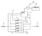
図1は、本発明の一実施態様に係る電気式脱イオン水製造装置の基本構成を示している。図1において、一側のカチオン交換膜と他側のアニオン交換膜で区画される室にイオン交換体(例えば、イオン交換樹脂、モノリス状有機多孔質イオン交換体、イオン交換繊維等)が充填されて弱塩基性イオンを含む被処理水5を脱塩処理する脱塩室1が構成される。脱塩室1の両側には濃縮室2が設けられ、これら脱塩室1および濃縮室2は、陽極を備えた陽極室と陰極を備えた陰極室からなる両電極室3、3(一方が陽極室、他方が陰極室)の間に配置されて本体部4が構成されている。図1においては、一つの脱塩室1の両側には濃縮室2が設けられた形態が示されているが、脱塩室1と濃縮室2は、複数組配置することが可能である。被処理水5は、上記脱塩室1内に充填されたイオン交換体の層を通過され、上記陽極と陰極との間に所定の電圧が印加され、上記両イオン交換膜を介して被処理水の流れに対して直角方向に直流電流が作用されることにより、両イオン交換膜の外側に配置された濃縮室2中を流れる濃縮水中に被処理水中の不純物イオンが電気的に排除されながら、処理水6としての脱イオン水が製造される。
Hereinafter, preferred embodiments of the present invention will be described with reference to the drawings.
FIG. 1 shows a basic configuration of an electric deionized water production apparatus according to an embodiment of the present invention. In FIG. 1, a chamber partitioned by a cation exchange membrane on one side and an anion exchange membrane on the other side is filled with an ion exchanger (eg, ion exchange resin, monolithic organic porous ion exchanger, ion exchange fiber, etc.). Thus, a desalting chamber 1 for desalting the treated water 5 containing weakly basic ions is configured.
上記電気式脱イオン水製造装置における本体部4の濃縮室2に対して、該濃縮室2を流れる濃縮水を循環させるために、循環ポンプ(図示略)と、濃縮水タンク7とを有する濃縮水循環系8が設けられている。この濃縮水循環系8では、脱塩室よりイオン交換膜を介し脱塩されたイオン性不純物等が濃縮されるため、濃度調整のため適宜被処理水5が補給水供給管9から補給水として補給されつつ、濃縮水が部分的にブロー系10を通して系外へ排出される。また、被処理水の一部は、電極水供給管11から各電極室3、3に電極水としても供給されて利用できるようになっている。電極室3、3では、水の電気分解により、陽極側では塩素や酸素、陰極側では水素等が副生するため、電極室3、3に供給された電極水は電極水流出管12により系外へ排出できるようになっている。排出された電極水は、不図示の気液分離装置で処理され水素の排気が行われることが好ましい。なお、この図1も概念図であり、通常、濃縮室、脱塩室は複数交互に配置された装置となっている。
A concentration pump having a circulation pump (not shown) and a
ここまでの構成は、基本的に図3に示した従来装置と同等の構成であるが、本発明に係る上記実施態様では、濃縮水循環系8に、とくに濃縮水タンク7に、pH調整薬剤を収容したpH調整薬剤タンク13と該pH調整薬剤を濃縮水タンク7内に注入する薬剤注入ポンプ14とを備えた、解離していない分子の濃縮室2側から脱塩室1側への逆拡散を防止する濃縮水のpH調整手段15が付設されている。さらに、濃縮水タンク7には、pH検出器(図示略)を設け、その検出信号を薬剤注入ポンプ14にフィードバックし、目標とするpH範囲内に制御できるようにしてもよい。ただし、被処理水の水質に変動がない場合には、pH検出器は設けなくてもよい。このpH調整手段15による濃縮水のpH調整は、基本的に、前述の如く、濃縮水中の弱塩基性物質をイオン化した状態に保つことができ、濃縮室側から脱塩室側への解離していない弱塩基性物質の分子の逆拡散を防止できるように行う。
The configuration so far is basically the same as that of the conventional apparatus shown in FIG. 3, but in the above-described embodiment according to the present invention, the pH adjusting agent is added to the concentrated water circulation system 8, particularly to the
このように構成された本実施態様に係る電気式脱イオン水製造装置においては、pH調整手段15により、濃縮水循環系8の濃縮水タンク7で目標とする範囲内のpHに(例えば、5以下のpHに)調整された濃縮水が、濃縮室2へと送られ、かつ、上記濃縮水循環系8を循環される。pH調整により、濃縮室2を流れる濃縮水中の弱塩基性物質はイオン化された状態に保たれ、解離していない弱塩基性物質の分子の状態で存在することが防止されるので、該分子が脱塩室1側に逆拡散することは回避される。とくに、濃縮水中に含まれる弱塩基性物質は、pHを酸性にすることによってイオンとなるため、解離していない分子がイオン交換膜を介して脱塩室1に逆拡散することがなく、処理水の水質を悪化させることがない。したがって、脱塩室1では、被処理水5中に含まれていた不純物イオンが、各イオン交換膜を通して濃縮室2へと電気的に排除され、目標とする脱塩処理が効率よく行われて、所望の(例えば、所望の抵抗率の)脱イオン水が処理水6として得られることになる。不純物イオンとしては、例えば、炭酸イオン、アンモニウムイオン、ナトリウムイオン、塩化物イオン、硫酸イオン等が挙げられ、これらの電荷を持つ形態のイオンが、陽極と陰極間に流れる電流により濃縮室2側に移動し、濃縮水中に排出される。
In the electric deionized water production apparatus according to this embodiment configured as described above, the pH is adjusted to a pH within a target range by the
なお、pH調整手段15によるpH調整のための薬剤の添加方法は、上記実施態様に限定されず、また、その添加濃度は装置の規模や設置場所などにより、適宜決定されればよい。
Note that the method of adding a drug for adjusting the pH by the
また、本発明に係る電気式脱イオン水製造装置の本体部の形態としては、特に制限されず、スパイラル型、同心円型あるいは平板積層型などのものが挙げられる。 In addition, the form of the main body of the electric deionized water production apparatus according to the present invention is not particularly limited, and examples thereof include a spiral type, a concentric circular type, and a flat plate laminated type.
さらに、本発明に係る電気式脱イオン水製造装置に供給される被処理水としては、特に制限されず、例えば、ボイラー水、発電所の復水、蒸気発生器のブローダウン水、下水、工業用水、河川水、半導体製造工場の半導体デバイスなどの洗浄排水又は濃縮室からの回収水などを逆浸透膜処理した透過水、また、半導体製造工場等のユースポイントで使用された回収水であって、逆浸透膜処理がされていない水が挙げられる。また、これらの混合水でもよい。 Further, the water to be treated supplied to the electric deionized water production apparatus according to the present invention is not particularly limited. For example, boiler water, power plant condensate, steam generator blowdown water, sewage, industrial Permeated water that has been treated with reverse osmosis membranes, such as cleaning water from river water, semiconductor devices in semiconductor manufacturing plants, or recovered water from concentration chambers, and recovered water used at point of use at semiconductor manufacturing plants, etc. And water that has not been subjected to reverse osmosis membrane treatment. Moreover, these mixed water may be sufficient.
本発明に係る電気式脱イオン水製造装置においては、脱塩室を、カチオン交換膜とアニオン交換膜の間に位置する中間イオン交換膜により2つの小脱塩室に区画し、被処理水が2つの小脱塩室を順次流れるように構成することができる。この形態により、より効率のよい脱塩処理を行うことが可能になる。この形態は、被処理水が、アンモニアを含む被処理水(例えば、pH9〜11、アンモニア濃度500μg/L〜100mg/Lのアンモニアを含む被処理水)からなる場合に、とくに有効である。被処理水がアンモニアを含む被処理水である場合には、2つの小脱塩室のうち被処理水が最初に通水される一方の小脱塩室にアニオン交換体が単床形態で充填され、他方の小脱塩室にカチオン交換体およびアニオン交換体が混床形態で充填されていることが好ましい。 In the electric deionized water production apparatus according to the present invention, the demineralization chamber is divided into two small demineralization chambers by an intermediate ion exchange membrane located between the cation exchange membrane and the anion exchange membrane, Two small desalting chambers can be configured to flow sequentially. This form makes it possible to perform a more efficient desalting treatment. This form is particularly effective when the water to be treated is water to be treated containing ammonia (for example, water to be treated containing ammonia having a pH of 9 to 11 and an ammonia concentration of 500 μg / L to 100 mg / L). When the water to be treated is treated water containing ammonia, anion exchanger is filled in a single-bed form in one of the two small desalting chambers where the treated water is first passed. The other small desalting chamber is preferably filled with a cation exchanger and an anion exchanger in a mixed bed form.
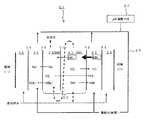
図2に上記構成を有する省電力型電気脱イオン水製造装置21の一例を例示する。
脱塩室22は、カチオン交換膜30とアニオン交換膜32及び両膜30,32の間に位置する中間イオン交換膜31により、2つの小脱塩室であるD1室23とD2室24に区画されており、最初に被処理水が流入するD1室23をアニオン交換体の単床脱塩室とし、続いてD1室23出口水が流入するD2室24をカチオン交換体とアニオン交換体の混床脱塩室とし、脱塩室22の両側に濃縮室25、その外側に電極室26が配置される。陰極側の濃縮室25と電極室26の間にはアニオン交換膜29が、陽極側の濃縮室25と電極室26の間にはカチオン交換膜33が配置される。濃縮室25にはpH調整手段27を備えた濃縮水循環系28により、目標とするpHに調整された濃縮水が循環される。なお、本例は省電力型脱イオン水製造装置の一例を例示したが、本例に限られることはなく、使用されるイオン交換膜やイオン交換体等は適宜選択される。
FIG. 2 illustrates an example of the power-saving electrodeionized
The desalting chamber 22 is divided into two small desalting chambers, a
このように脱塩室を2つの小脱塩室D1室23、D2室24とすることにより、図2に示すように例えば、脱塩室22の陽極側に位置する濃縮室25内の濃縮水中に、アンモニアが分子の形態(NH3)で存在していた場合、アンモニアが処理水に流出するには、脱塩室側アニオン交換膜を逆拡散してD1室23内に移動し、そこから更に中間イオン交換膜としてのアニオン交換膜を逆拡散してD2室24内に移動しなければならない。一方、被処理水の流路にそってD2室24入口からから流入したアンモニアはD2室24内のカチオン交換体により処理され、陰極側濃縮室に排出されるため、アンモニアの処理水への流出は抑制される。
Thus, by making the desalination chamber into two small desalination
次に、実施例を挙げて本発明を更に具体的に説明するが、これは単に例示であって、本発明を制限するものではない。なお、以下の実施例において、アンモニアの定量方法としては、JIS−B8224「インドフェノール青吸光光度法」を用いた。 EXAMPLES Next, although an Example is given and this invention is demonstrated more concretely, this is only an illustration and does not restrict | limit this invention. In the following examples, JIS-B8224 “Indophenol blue absorptiometry” was used as a method for quantifying ammonia.
実施例1
アンモニアを含む被処理水を混床脱塩セルで脱塩処理した。下記の装置仕様、運転条件及び図1に示したフローの電気式脱イオン水製造装置を使用し、アンモニウムイオン20mg/L、ナトリウムイオン1mg/L、塩化物イオン1mg/L、硫酸イオン1mg/Lの被処理水から脱イオン水を製造した。評価方法は印加電圧100V、印加電流1.2Aにおける100時間連続運転後の処理水の抵抗率とした。結果は、処理水の抵抗率は15.8MΩ−cmであった。
Example 1
The treated water containing ammonia was desalted in a mixed bed desalting cell. Using the following equipment specifications, operating conditions and the electric deionized water production system with the flow shown in Fig. 1, ammonium ion 20mg / L, sodium ion 1mg / L, chloride ion 1mg / L, sulfate ion 1mg / L Deionized water was produced from the treated water. The evaluation method was the resistivity of treated water after 100 hours of continuous operation at an applied voltage of 100 V and an applied current of 1.2 A. As a result, the resistivity of the treated water was 15.8 MΩ-cm.
(運転の条件)
・電気式脱イオン水製造装置;図1に示した電気式脱イオン水製造装置(以下、EDIと略称することもある。)
・脱塩室;幅75mm、高さ330mm、厚さ4mm
・脱塩室に充填したイオン交換樹脂;アニオン交換樹脂(A)とカチオン交換樹脂(K)の混合イオン交換樹脂(混合比は体積比でA:K=1:1)
・濃縮室;幅75mm、高さ330mm、厚さ1mm
・装置全体の流量;60L/h
・循環タンク;液相部容量20L
・濃縮水のpHが1.5となるよう塩酸を加えた。
(Operating conditions)
Electric deionized water production apparatus; electric deionized water production apparatus shown in FIG. 1 (hereinafter, sometimes referred to as EDI)
・ Desalination chamber: width 75mm, height 330mm, thickness 4mm
-Ion exchange resin filled in the desalting chamber; mixed ion exchange resin of anion exchange resin (A) and cation exchange resin (K) (mixing ratio is A: K = 1: 1 by volume)
・ Concentration chamber: width 75mm, height 330mm, thickness 1mm
・ Flow rate of the entire device: 60 L / h
・ Circulating tank; Liquid phase capacity 20L
-Hydrochloric acid was added so that the pH of the concentrated water was 1.5.
比較例1
実施例1に比べ、濃縮水のpHを調整せず、pH10.0のままとした。この場合、処理水の抵抗率は1.8MΩ−cmであった。
Comparative Example 1
Compared to Example 1, the pH of the concentrated water was not adjusted and the pH was kept at 10.0. In this case, the resistivity of the treated water was 1.8 MΩ-cm.
実施例2
実施例1に比べ、脱塩室が、カチオン交換膜とアニオン交換膜の間に位置する中間イオン交換膜により2つの小脱塩室に区画されており、被処理水が2つの小脱塩室を順次流れるように構成されている、いわゆる省電力型の電気式脱イオン水製造装置(以下、省電力型EDIと略称することもある。)で、弱塩基性の被処理水をカチオン単床+混床脱塩セルで脱塩処理し、カチオン単床→混床の順で通水した。電気式脱イオン水製造装置の本体部が下記仕様の装置である以外、実施例1と同様の方法で行った。結果は、処理水の抵抗率は16.6MΩ−cmであった。
Example 2
Compared to Example 1, the desalination chamber is partitioned into two small desalination chambers by an intermediate ion exchange membrane located between the cation exchange membrane and the anion exchange membrane, and the water to be treated is divided into two small desalination chambers. In a so-called power-saving electric deionized water production apparatus (hereinafter sometimes abbreviated as power-saving EDI). + Desalination treatment was performed in a mixed bed desalting cell, and water was passed in the order of cation single bed → mixed bed. It was carried out in the same manner as in Example 1 except that the main body of the electric deionized water production apparatus was an apparatus having the following specifications. As a result, the resistivity of the treated water was 16.6 MΩ-cm.
(運転の条件)
・電気式脱イオン水製造装置;省電力型EDI
・中間イオン交換膜;アニオン交換膜
・小脱塩室(D2);幅75mm、高さ330mm、厚さ4mm
・小脱塩室(D2)に充填したイオン交換樹脂;アニオン交換樹脂(A)とカチオン交換樹脂(K)の混合イオン交換樹脂(混合比は体積比でA:K=1:1)
・小脱塩室(D1);幅75mm、高さ330mm、厚さ8mm
・小脱塩室(D1)充填イオン交換樹脂;カチオン交換樹脂
・濃縮室;幅75mm、高さ330mm、厚さ1mm
・装置全体の流量;60L/h
・循環タンク;容量20L
・濃縮水のpHが1.5±0.5となるよう塩酸を加えた。
(Operating conditions)
・ Electric deionized water production equipment; power-saving EDI
・ Intermediate ion exchange membrane; anion exchange membrane ・ Small desalination chamber (D2); width 75mm, height 330mm, thickness 4mm
-Ion exchange resin filled in small desalting chamber (D2); mixed ion exchange resin of anion exchange resin (A) and cation exchange resin (K) (mixing ratio is A: K = 1: 1 by volume)
・ Small desalination chamber (D1); width 75mm, height 330mm, thickness 8mm
・ Small desalination chamber (D1) filled ion exchange resin; cation exchange resin ・ concentration chamber; width 75 mm, height 330 mm, thickness 1 mm
・ Flow rate of the entire device: 60 L / h
・ Circulating tank; capacity 20L
-Hydrochloric acid was added so that the pH of the concentrated water was 1.5 ± 0.5.
比較例2
実施例2に比べ、濃縮水のpHを調整せず、pH10.0のままとした。この場合、処理水の抵抗率は6.2MΩ−cmであった。
Comparative Example 2
Compared to Example 2, the pH of the concentrated water was not adjusted and the pH was kept at 10.0. In this case, the resistivity of the treated water was 6.2 MΩ-cm.
実施例3
アンモニアを含む弱塩基性の被処理水をアニオン単床+混床脱塩セルで脱塩処理した。電気式脱イオン水製造装置の本体部が下記仕様の装置である以外、実施例2と同様の方法で行った。結果は、処理水の抵抗率は17.6MΩ−cmであった。
Example 3
Weakly basic water to be treated containing ammonia was desalted in an anion single bed + mixed bed desalting cell. The method was the same as in Example 2 except that the main body of the electric deionized water production apparatus was an apparatus having the following specifications. As a result, the resistivity of the treated water was 17.6 MΩ-cm.
(運転の条件)
・電気式脱イオン水製造装置;省電力型EDI
・中間イオン交換膜;アニオン交換膜
・小脱塩室(D2);幅75mm、高さ330mm、厚さ4mm
・小脱塩室(D2)に充填したイオン交換樹脂;アニオン交換樹脂(A)とカチオン交換樹脂(K)の混合イオン交換樹脂(混合比は体積比でA:K=1:1)
・小脱塩室(D1);幅75mm、高さ330mm、厚さ8mm
・小脱塩室(D1)充填イオン交換樹脂;アニオン交換樹脂
・濃縮室;幅75mm、高さ330mm、厚さ1mm
・装置全体の流量;60L/h
・循環タンク;容量20L
・濃縮水のpHが1.5±0.5となるよう塩酸を加えた。
(Operating conditions)
・ Electric deionized water production equipment; power-saving EDI
・ Intermediate ion exchange membrane; anion exchange membrane ・ Small desalination chamber (D2); width 75mm, height 330mm, thickness 4mm
-Ion exchange resin filled in small desalting chamber (D2); mixed ion exchange resin of anion exchange resin (A) and cation exchange resin (K) (mixing ratio is A: K = 1: 1 by volume)
・ Small desalination chamber (D1); width 75mm, height 330mm, thickness 8mm
・ Small desalination chamber (D1) filled ion exchange resin; anion exchange resin ・ concentration chamber; width 75 mm, height 330 mm, thickness 1 mm
・ Flow rate of the entire device: 60 L / h
・ Circulating tank; capacity 20L
-Hydrochloric acid was added so that the pH of the concentrated water was 1.5 ± 0.5.
比較例3
実施例3に比べ、濃縮水のpHを調整せず、pH13.5のままとした。この場合、処理水の抵抗率は10.2MΩ−cmであった。
Comparative Example 3
Compared to Example 3, the pH of the concentrated water was not adjusted and the pH was kept at 13.5. In this case, the resistivity of the treated water was 10.2 MΩ-cm.
上記実施例1〜3によれば、処理水の抵抗率が比較例1〜3に比べて高く、高純度の処理水が得られた。 According to the said Examples 1-3, the resistivity of treated water was high compared with Comparative Examples 1-3, and the highly purified treated water was obtained.
とくに、実施例3におけるアニオン交換体単床脱塩室+混床脱塩室の形態では、図2に示したように、アンモニアはアニオン交換体単床脱塩室に逆拡散後、混床脱塩室でカチオン樹脂に捕捉・排出されるものもある。また、混床脱塩室まで逆拡散で到達するには、アニオン交換膜を2回、逆拡散する必要がある。このため、混床脱塩室だけの装置より良好な結果が得られた。 In particular, in the form of the anion exchanger single bed demineralization chamber + mixed bed demineralization chamber in Example 3, as shown in FIG. Some are captured and discharged by the cationic resin in the salt chamber. Further, in order to reach the mixed bed desalting chamber by back diffusion, it is necessary to back diffuse the anion exchange membrane twice. For this reason, a better result was obtained than the apparatus having only the mixed bed desalination chamber.
なお、上記のようにpH調節手段によりpHを調節したときのほうが、抵抗率は高いが、不純物イオン除去を目的とした場合、実用上は10MΩ−cmであれば、高濃度の弱電解物質が被処理水中に含有する場合、該抵抗率の低下はアンモニア分子の逆拡散による処理水への流出が原因である場合が多く、処理水中の不純物イオンは十分に低い場合が多い、その場合酸を加えなくても(アニオン単床+混床の装置だけでも)、十分な水質を得られることもある。 In addition, when the pH is adjusted by the pH adjusting means as described above, the resistivity is higher. However, for the purpose of removing impurity ions, if it is practically 10 MΩ-cm, a high-concentration weak electrolytic substance is present. When contained in the water to be treated, the decrease in the resistivity is often caused by outflow to the treated water due to the back diffusion of ammonia molecules, and the impurity ions in the treated water are often sufficiently low. Even if it is not added (only an anion single bed + mixed bed apparatus), sufficient water quality may be obtained.
本発明に係る電気式脱イオン水製造装置は、被処理水が弱塩基性イオンを含む場合の、あらゆる分野の脱イオン水の製造に適用でき、とくに、ボイラー水や発電所の復水、発電所の蒸気発生器器内水等として使用される脱イオン水の製造に好適なものである。 The electric deionized water production apparatus according to the present invention can be applied to the production of deionized water in all fields when the water to be treated contains weak basic ions, and in particular, boiler water, condensate of power plants, power generation This is suitable for the production of deionized water used as the water in the steam generator of the plant.
1 脱塩室
2 濃縮室
3 電極室(一方が陽極室、他方が陰極室)
4 本体部
5 被処理水
6 処理水としての脱イオン水
7 濃縮水タンク
8 濃縮水循環系
9 補給水供給管
10 ブロー系
11 電極水供給管
12 電極水流出管
13 pH調整薬剤タンク
14 薬剤注入ポンプ
15 pH調整手段
21 電気式脱イオン水製造装置
22 脱塩室
23、24 小脱塩室
25 濃縮室
26 電極室
27 pH調整手段
28 濃縮水循環系
29、32 アニオン交換膜
30、33 カチオン交換膜
31 中間イオン交換膜
1
4 Main Body 5 Water to be treated 6 Deionized water as treated
Claims (5)
Priority Applications (1)
| Application Number | Priority Date | Filing Date | Title |
|---|---|---|---|
| JP2006093819A JP2007268331A (en) | 2006-03-30 | 2006-03-30 | Apparatus for manufacturing electrically deionized water |
Applications Claiming Priority (1)
| Application Number | Priority Date | Filing Date | Title |
|---|---|---|---|
| JP2006093819A JP2007268331A (en) | 2006-03-30 | 2006-03-30 | Apparatus for manufacturing electrically deionized water |
Publications (1)
| Publication Number | Publication Date |
|---|---|
| JP2007268331A true JP2007268331A (en) | 2007-10-18 |
Family
ID=38671685
Family Applications (1)
| Application Number | Title | Priority Date | Filing Date |
|---|---|---|---|
| JP2006093819A Pending JP2007268331A (en) | 2006-03-30 | 2006-03-30 | Apparatus for manufacturing electrically deionized water |
Country Status (1)
| Country | Link |
|---|---|
| JP (1) | JP2007268331A (en) |
Cited By (6)
| Publication number | Priority date | Publication date | Assignee | Title |
|---|---|---|---|---|
| JP2010142727A (en) * | 2008-12-18 | 2010-07-01 | Japan Organo Co Ltd | Electric deionized water producing apparatus |
| CN103922442A (en) * | 2014-04-10 | 2014-07-16 | 北京工业大学 | Method for efficiently enriching ammonia nitrogen ions in water based on membrane and electrode |
| US9023184B2 (en) | 2010-09-14 | 2015-05-05 | Organo Corporation | Electric device for producing deionized water |
| CN106053118A (en) * | 2016-07-21 | 2016-10-26 | 北京国电富通科技发展有限责任公司 | Over-current assembly test device |
| CN107702904A (en) * | 2017-09-20 | 2018-02-16 | 北京国电富通科技发展有限责任公司 | Converter valve cooling system colds and heat succeed each other test device and method |
| CN111763952A (en) * | 2020-07-01 | 2020-10-13 | 辽宁黄花沟田园综合体开发有限公司 | Desalination method and device for preparing ultra-high-purity hypochlorous acid aqueous solution by using salt as raw material |
Citations (12)
| Publication number | Priority date | Publication date | Assignee | Title |
|---|---|---|---|---|
| JPH10323673A (en) * | 1997-03-28 | 1998-12-08 | Asahi Glass Co Ltd | Deionized water-producing method |
| JPH1147560A (en) * | 1997-07-29 | 1999-02-23 | Japan Organo Co Ltd | Secondary system line water treatment plant for pressurized water type atomic power plant |
| JPH11165177A (en) * | 1997-12-05 | 1999-06-22 | Japan Organo Co Ltd | Electric deionized water generator |
| JPH11188241A (en) * | 1997-10-15 | 1999-07-13 | Elf Atochem Sa | Desalting of sulfone amide aqueous solution |
| JP2001079552A (en) * | 1999-09-14 | 2001-03-27 | Japan Organo Co Ltd | Electric deionizing device |
| JP2001170630A (en) * | 1999-12-15 | 2001-06-26 | Japan Organo Co Ltd | Pure water production device |
| JP2001252672A (en) * | 2000-03-10 | 2001-09-18 | Japan Organo Co Ltd | Operation method for electric deionized water production device |
| JP2001259645A (en) * | 2000-03-23 | 2001-09-25 | Japan Organo Co Ltd | Deionized water production method |
| JP2003170169A (en) * | 2001-12-07 | 2003-06-17 | Japan Organo Co Ltd | Electrically operated deionized water producing system and method |
| JP2004267907A (en) * | 2003-03-07 | 2004-09-30 | Kurita Water Ind Ltd | Electric deionization apparatus and operating method therefor |
| JP2007147453A (en) * | 2005-11-28 | 2007-06-14 | Hitachi Ltd | Method and device for processing ammonia-containing regenerated waste solution from condensate demineralizer |
| JP2007245120A (en) * | 2006-03-20 | 2007-09-27 | Japan Organo Co Ltd | Electrically operated apparatus for producing deionized water |
-
2006
- 2006-03-30 JP JP2006093819A patent/JP2007268331A/en active Pending
Patent Citations (12)
| Publication number | Priority date | Publication date | Assignee | Title |
|---|---|---|---|---|
| JPH10323673A (en) * | 1997-03-28 | 1998-12-08 | Asahi Glass Co Ltd | Deionized water-producing method |
| JPH1147560A (en) * | 1997-07-29 | 1999-02-23 | Japan Organo Co Ltd | Secondary system line water treatment plant for pressurized water type atomic power plant |
| JPH11188241A (en) * | 1997-10-15 | 1999-07-13 | Elf Atochem Sa | Desalting of sulfone amide aqueous solution |
| JPH11165177A (en) * | 1997-12-05 | 1999-06-22 | Japan Organo Co Ltd | Electric deionized water generator |
| JP2001079552A (en) * | 1999-09-14 | 2001-03-27 | Japan Organo Co Ltd | Electric deionizing device |
| JP2001170630A (en) * | 1999-12-15 | 2001-06-26 | Japan Organo Co Ltd | Pure water production device |
| JP2001252672A (en) * | 2000-03-10 | 2001-09-18 | Japan Organo Co Ltd | Operation method for electric deionized water production device |
| JP2001259645A (en) * | 2000-03-23 | 2001-09-25 | Japan Organo Co Ltd | Deionized water production method |
| JP2003170169A (en) * | 2001-12-07 | 2003-06-17 | Japan Organo Co Ltd | Electrically operated deionized water producing system and method |
| JP2004267907A (en) * | 2003-03-07 | 2004-09-30 | Kurita Water Ind Ltd | Electric deionization apparatus and operating method therefor |
| JP2007147453A (en) * | 2005-11-28 | 2007-06-14 | Hitachi Ltd | Method and device for processing ammonia-containing regenerated waste solution from condensate demineralizer |
| JP2007245120A (en) * | 2006-03-20 | 2007-09-27 | Japan Organo Co Ltd | Electrically operated apparatus for producing deionized water |
Cited By (7)
| Publication number | Priority date | Publication date | Assignee | Title |
|---|---|---|---|---|
| JP2010142727A (en) * | 2008-12-18 | 2010-07-01 | Japan Organo Co Ltd | Electric deionized water producing apparatus |
| US9023184B2 (en) | 2010-09-14 | 2015-05-05 | Organo Corporation | Electric device for producing deionized water |
| CN103922442A (en) * | 2014-04-10 | 2014-07-16 | 北京工业大学 | Method for efficiently enriching ammonia nitrogen ions in water based on membrane and electrode |
| CN106053118A (en) * | 2016-07-21 | 2016-10-26 | 北京国电富通科技发展有限责任公司 | Over-current assembly test device |
| CN107702904A (en) * | 2017-09-20 | 2018-02-16 | 北京国电富通科技发展有限责任公司 | Converter valve cooling system colds and heat succeed each other test device and method |
| CN107702904B (en) * | 2017-09-20 | 2019-12-31 | 北京国电富通科技发展有限责任公司 | Converter valve cooling system cold and hot alternation testing device and method |
| CN111763952A (en) * | 2020-07-01 | 2020-10-13 | 辽宁黄花沟田园综合体开发有限公司 | Desalination method and device for preparing ultra-high-purity hypochlorous acid aqueous solution by using salt as raw material |
Similar Documents
| Publication | Publication Date | Title |
|---|---|---|
| KR100426669B1 (en) | Electrodeionization apparatus and pure water producing apparatus | |
| US6274019B1 (en) | Electrodeionization apparatus | |
| US7699968B2 (en) | Water purifying system | |
| KR101138382B1 (en) | Electric type deionized water production apparatus operating method, electric type deionized water production system, and electric type deionized water production apparatus | |
| KR20040086244A (en) | Fractional deionization process | |
| JP4960288B2 (en) | Electric deionized water production apparatus and deionized water production method | |
| JP2011110515A (en) | Method and apparatus for purifying ion exchange resin | |
| JP2007268331A (en) | Apparatus for manufacturing electrically deionized water | |
| JP2004167291A (en) | Electric deionization apparatus | |
| JP3951642B2 (en) | Method for operating electrodeionization apparatus, electrodeionization apparatus and electrodeionization system | |
| JP2011000576A (en) | Electric deionized water producing apparatus and method for producing deionized water | |
| JP5114307B2 (en) | Electric deionized water production equipment | |
| JP3773178B2 (en) | Electric deionized water production apparatus and production method | |
| JP3788318B2 (en) | Electrodeionization apparatus and electrodeionization method | |
| JP3952127B2 (en) | Electrodeionization treatment method | |
| JP3570279B2 (en) | Electric desalination equipment | |
| JP2009208046A (en) | Apparatus for producing electrodeionization water | |
| JP2007245120A (en) | Electrically operated apparatus for producing deionized water | |
| JP4505965B2 (en) | Pure water production method | |
| JP3570350B2 (en) | Electrodeionization equipment and pure water production equipment | |
| JP4662277B2 (en) | Electrodeionization equipment | |
| JP2003001258A (en) | Electrolytic deionizing apparatus | |
| JP5186605B2 (en) | Electric deionized water production apparatus and deionized water production method | |
| JP3700244B2 (en) | Pure water production equipment | |
| JP4300828B2 (en) | Electrodeionization apparatus and operation method thereof |
Legal Events
| Date | Code | Title | Description |
|---|---|---|---|
| A621 | Written request for application examination |
Free format text: JAPANESE INTERMEDIATE CODE: A621 Effective date: 20090224 |
|
| A977 | Report on retrieval |
Free format text: JAPANESE INTERMEDIATE CODE: A971007 Effective date: 20101022 |
|
| A131 | Notification of reasons for refusal |
Free format text: JAPANESE INTERMEDIATE CODE: A131 Effective date: 20120306 |
|
| A02 | Decision of refusal |
Free format text: JAPANESE INTERMEDIATE CODE: A02 Effective date: 20120629 |