JP2007143064A - Imaging device and imaging method - Google Patents
Imaging device and imaging method Download PDFInfo
- Publication number
- JP2007143064A JP2007143064A JP2005337491A JP2005337491A JP2007143064A JP 2007143064 A JP2007143064 A JP 2007143064A JP 2005337491 A JP2005337491 A JP 2005337491A JP 2005337491 A JP2005337491 A JP 2005337491A JP 2007143064 A JP2007143064 A JP 2007143064A
- Authority
- JP
- Japan
- Prior art keywords
- image data
- imaging
- image
- panoramic
- display
- Prior art date
- Legal status (The legal status is an assumption and is not a legal conclusion. Google has not performed a legal analysis and makes no representation as to the accuracy of the status listed.)
- Pending
Links
Images
Landscapes
- Studio Devices (AREA)
Abstract
Description
本発明は、パノラマ画像を撮像可能な撮像装置及び撮像方法に関する。 The present invention relates to an imaging apparatus and an imaging method capable of imaging a panoramic image.
撮像装置の一例であるデジタルカメラは、従来、アスペクト比が横4:縦3のディスプレイを備えるものが一般的である。このデジタルカメラを用いてパノラマ画像を撮像する(以下、「パノラマ撮像」と呼ぶ)方法が提案されている(特許文献1参照)。 Conventionally, a digital camera that is an example of an imaging apparatus is generally provided with a display having an aspect ratio of 4: 4 in the horizontal direction. A method of capturing a panoramic image using this digital camera (hereinafter referred to as “panoramic imaging”) has been proposed (see Patent Document 1).
従来のデジタルカメラは、一般に、パノラマ画像をアスペクト比が横4:縦3のディスプレイに収まるように変倍して、ディスプレイに表示する。
パノラマ画像は、一般に、アスペクト比が横4:縦3の画像を横に複数つなぎ合わせたものであるため、横4:縦3よりもさらに横長である。したがって、パノラマ画像の全体を、従来のデジタルカメラが備える、アスペクト比が横4:縦3のディスプレイに表示すると、表示される画像は小さくなり、ユーザがパノラマ画像を視認することが困難である。 In general, a panoramic image is an image in which a plurality of images having an aspect ratio of 4: 4 in the horizontal direction are connected in a horizontal direction, and thus is more horizontally long than 4: 4 in the horizontal direction. Therefore, when the entire panoramic image is displayed on a display with an aspect ratio of 4: 4 in a conventional digital camera, the displayed image becomes small and it is difficult for the user to visually recognize the panoramic image.
本発明はこのような状況に鑑みてなされたものであり、ユーザがパノラマ画像を視認することを容易にする撮像装置と撮像方法を提供することを目的とする。 SUMMARY An advantage of some aspects of the invention is that it provides an imaging apparatus and an imaging method that make it easy for a user to visually recognize a panoramic image.
上記課題を解決するために、本発明の撮像装置は、撮像して画像データを取得する撮像手段と、前記撮像手段により取得された、複数の画像データから生成されたパノラマ画像データを取得するパノラマ画像取得手段と、前記画像データ及び前記パノラマ画像データのうち少なくともいずれかを表示する表示手段と、を備え、前記表示手段のアスペクト比は横16:縦9であることを特徴とする。 In order to solve the above problems, an imaging apparatus according to the present invention includes an imaging unit that captures an image and acquires image data, and a panorama that acquires panoramic image data generated from the plurality of image data acquired by the imaging unit. An image acquisition unit; and a display unit configured to display at least one of the image data and the panoramic image data, wherein the aspect ratio of the display unit is 16: 9.
また、本発明の撮像方法は、撮像して画像データを取得する撮像工程と、前記撮像工程により取得された、複数の画像データから生成されたパノラマ画像データを取得するパノラマ画像取得工程と、前記画像データ及び前記パノラマ画像データのうち少なくともいずれかを表示手段に表示する表示工程と、を備え、前記表示手段のアスペクト比は横16:縦9であることを特徴とする。 The imaging method of the present invention includes an imaging step of capturing and acquiring image data, a panoramic image acquisition step of acquiring panoramic image data generated from a plurality of image data acquired by the imaging step, A display step of displaying at least one of the image data and the panoramic image data on a display means, wherein the aspect ratio of the display means is 16: 9 horizontally.
なお、その他の本発明の特徴は、添付図面及び以下の発明を実施するための最良の形態の記載によっていっそう明らかになるものである。 Other features of the present invention will become more apparent from the accompanying drawings and the following description of the best mode for carrying out the invention.
以上の構成により、本発明の撮像装置と撮像方法によれば、ユーザがパノラマ画像を視認することが容易になる。 With the above configuration, according to the imaging apparatus and imaging method of the present invention, it becomes easy for the user to visually recognize the panoramic image.
以下、添付図面を参照して、本発明の上位概念、中位概念および下位概念の理解に役立つ実施形態を示す。なお、以下の実施形態に含まれる概念について、そのすべてが特許請求の範囲に記載されているとは限らない。ただし、これは特許発明の技術的範囲から意識的に除外したのではないことを理解していただきたい。 DETAILED DESCRIPTION OF THE PREFERRED EMBODIMENTS Embodiments useful for understanding the general concept, intermediate concept and subordinate concept of the present invention will be described below with reference to the accompanying drawings. Note that not all of the concepts included in the following embodiments are described in the claims. However, it should be understood that this is not intentionally excluded from the technical scope of the patented invention.
[第1の実施形態]
<デジタルカメラ100の構成>
図1は、本発明を適用する撮影装置であるデジタルカメラ100の構成を示す機能ブロック図である。
[First Embodiment]
<Configuration of
FIG. 1 is a functional block diagram showing a configuration of a
制御部101は、デジタルカメラ100の各構成要素を制御することにより、デジタルカメラ100全体を制御する。
The
撮像部102は、例えばCCDなどの固体撮像素子により構成され、光信号をアナログ電気信号に変換する。
The
信号処理部103は、撮像部102から得られたアナログ電気信号をA/D変換によりデジタル電気信号とする。デジタル電気信号が、すなわち、撮像された画像データである。信号処理部103はまた、画像データに対して、輝度補正やホワイトバランス処理などの画像処理を施す。
The
表示制御部104は、信号処理部103から得られた画像データを表示部106に表示する制御を行う。
The
表示用メモリ105は、表示制御部104から送られてきた、表示部106に表示するための画像データを格納する。
The
表示部106は、例えば液晶パネルなどにより構成され、表示用メモリ105に格納されている画像データが示す画像を表示する。なお、表示部106のアスペクト比は、横16:縦9である。
The display unit 106 is composed of a liquid crystal panel, for example, and displays an image indicated by image data stored in the
圧縮・伸長部107は、信号処理部103から得られた画像データ及びメモリカード109から読み出された画像データを圧縮したり伸張したりする。画像データの圧縮は、例えばJPEG符号化により行われる。
The compression /
メモリカードI/F108は、メモリカード109に対して画像データを読み書きするためのインタフェースである。
The memory card I /
メモリカード109は、例えばフラッシュメモリなどにより構成され、画像データを格納する。メモリカード109はデジタルカメラ100に対して着脱可能であってもよいし、内蔵されていてもよい。また、画像データを格納可能であれば、メモリカード109の代わりにHDD(ハードディスクドライブ)などが用いられてもよい。
The
操作部110は、ユーザがデジタルカメラ100に様々な指示を与えるために使用されるものである。操作部110は例えば、再生スイッチ、画像送りスイッチ、画像戻しスイッチ、画像表示キー、設定キー、読み出しキーなどから構成される。
The
光学レンズ111は、被写体の光学像を撮像部102に結像させる。
The
商用電源112は、ACアダブタを介してデジタルカメラ100に電力を供給する。
The
定電圧発生回路113は、商用電源112から供給された電力の電圧を、制御部101などの各構成要素に適切な電圧に変換して、各構成要素に供給する。
The constant
充電回路114は、二次電池116を充電するために供給する電力を制御する回路である。
The
切替器115は、デジタルカメラ100の各構成要素に、二次電池116から電力を供給するか否かを切り替える。
The
二次電池116は、リチウムイオン電池やニッケル水素電池から構成され、デジタルカメラ100の各構成要素に電力を供給する。
The secondary battery 116 is composed of a lithium ion battery or a nickel metal hydride battery, and supplies power to each component of the
外部装置I/F117は、デジタルカメラ100と外部装置を接続するためのUSBポートやIEEE1394ポートなどを制御するためのインタフェースである。
The external device I / F 117 is an interface for controlling a USB port, an IEEE 1394 port, or the like for connecting the
外部装置118は、プリンタやPC(パーソナルコンピュータ)であり、外部装置I/F117を介してデジタルカメラ100とデータの送受信をすることができる。
The
RAM119は、制御部101がワークエリアとして使用したり、パノラマ画像を生成するための画像データを一時的に記憶したりするためのメモリである。
The
<パノラマ撮像処理の流れ>
図2は、第1の実施形態における、デジタルカメラ100を用いたパノラマ撮像処理の流れを示すフローチャートである。本フローチャートにおける処理により、デジタルカメラ100は、アスペクト比が横4:縦3の撮像画像を横に複数並べて、パノラマ画像を生成する。
<Flow of panorama imaging process>
FIG. 2 is a flowchart showing a flow of panorama imaging processing using the
ステップS201で、制御部101は、デジタルカメラ100の電源がONであり、かつ、静止画撮像モードに設定されているか否かを判定する。ここでの判定は、制御部101が操作部110に含まれるスイッチ等の状態を検出することにより行われる。デジタルカメラ100の電源がONであり、かつ、静止画撮像モードに設定されていれば、ステップS202に進む。
In step S201, the
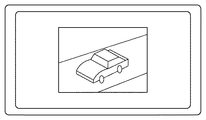
ステップS202で、制御部101は、光学レンズ111が現在捉えている画像を表示部106に表示する。詳述すると、光学レンズ111から入射した光学像が撮像部102上に結像してアナログ電気信号に変換され、アナログ電気信号は信号処理部103において画像データに変換される。表示制御部104は、制御部101の指示を受けて画像データの示す画像を表示部106に表示する。図3は、ステップS202において画像が表示部106に表示される様子の一例を示す図である。
In step S <b> 202, the
なお、ステップS202で表示される画像のアスペクト比は横4:縦3である。また、表示部106はEVFとして機能するため、光学レンズ111が捉えている画像の変化に追随して、表示部106に表示される画像も変化する。
Note that the aspect ratio of the image displayed in step S202 is horizontal 4: vertical 3. In addition, since the display unit 106 functions as an EVF, the image displayed on the display unit 106 also changes following the change in the image captured by the
ステップS203で、制御部101は、デジタルカメラ100がパノラマ撮像モードに設定されているか否かを判定する。ここでの判定は、制御部101が操作部110に含まれるスイッチ等の状態を検出することにより行われる。デジタルカメラ100がパノラマ撮像モードに設定されていれば、ステップS204に進む。
In step S203, the
ステップS204で、制御部101は、ステップS202では表示部106の中央に表示していた画像を、表示部106の左端に表示する。また、パノラマ画像を構成する画像データの数を示す変数Nを1に設定する。次いで、ステップS205に進む。
In step S <b> 204, the
ステップS205で、制御部101は、パノラマ撮像モードを終了する指示を受信したか否かを判定する。パノラマ撮像モードを終了する指示は、例えば、ユーザが操作部110を介して制御部101に与えることができる。パノラマ撮像モードを終了する指示を受信した場合は処理を終了し、受信していない場合はステップS206に進む。
In step S205, the
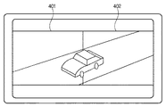
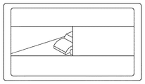
ステップS206での処理は、N=1か、N>1によって異なる。図4及び図5は、ステップS206において表示部106に表示される画像の一例を示す図である。 The processing in step S206 differs depending on whether N = 1 or N> 1. 4 and 5 are diagrams illustrating examples of images displayed on the display unit 106 in step S206.
N=1の場合、表示部106には、図4に示すような表示がなされる。表示領域401はEVFとして機能し、ステップS204と同様、光学レンズ111が現在捉えている画像が表示される。
When N = 1, the display unit 106 displays as shown in FIG. The
N>1の場合、表示部106には、図5に示すような表示がなされる。表示領域401には、直前に撮像された画像が表示される。表示領域402はEVFとして機能し、光学レンズ111が現在捉えている画像が表示される。ユーザは表示領域401に表示される画像と表示領域402に表示される画像の境界線が一致するように次の撮像を行うことにより、パノラマ画像を撮像することができる。
When N> 1, the display unit 106 displays as shown in FIG. In the
ステップS207で、制御部101は、操作部110に含まれるシャッターボタンが押下されたか否かを判定する。押下された場合はステップS208に進み、押下されなかった場合はステップS206に戻る。
In step S207, the
ステップS208で、制御部101は、信号処理部103や圧縮・伸長部107などを制御することにより撮像を行い、N番目の画像データを取得する。
In step S208, the
ステップS209で、制御部101は、ステップS208で取得した画像データをメモリカード109に記録する。
In step S209, the
ステップS210で、制御部101は、メモリカード109から1〜N番目の画像データをすべて読み出し、RAM119に格納する。
In step S <b> 210, the
ステップS211で、制御部101は、ステップS210でRAM119に格納した画像データを横に並べて表示部106に表示する。N=2の場合、ステップS211で表示部106に表示される画像は、例えば図5に示すようになる。ただし、ステップS206における表示と異なり、表示領域402はEVFとして機能する訳ではなく、2番目に撮像された画像が表示される。
In step S211, the
ここで重要なことは、表示部106のアスペクト比が横16:縦9であり、横4:縦3に比べて横長であることである。そのため、アスペクト比が横4:縦3の画像を複数並べてパノラマ画像として表示しても、表示部106のアスペクト比が横4:縦3の場合に比べて、表示されるパノラマ画像が大きくなる。 What is important here is that the aspect ratio of the display unit 106 is horizontal 16: vertical 9 and is wider than horizontal 4: vertical 3. For this reason, even when a plurality of images with an aspect ratio of 4: 3 in the horizontal direction are arranged and displayed as a panoramic image, the displayed panoramic image is larger than when the aspect ratio of the display unit 106 is 4: 4 in the horizontal direction.
ステップS212で、Nに1を加えてステップS205に戻り、同様の処理を繰り返す。 In step S212, 1 is added to N, the process returns to step S205, and the same processing is repeated.
なお、ステップS205〜S212の処理が複数回繰り返されることにより、ステップS211で表示されるパノラマ画像を構成する画像データの数が増える。図5では、表示部106は2つの表示領域を持つのみである。しかし、例えばN=5となれば、5枚の画像からパノラマ画像が生成されるため、表示部106は横に並ぶ5つの表示領域に分割され、それぞれにN=1〜5番目の画像が表示される。 Note that the number of image data constituting the panoramic image displayed in step S211 is increased by repeating the processes in steps S205 to S212 a plurality of times. In FIG. 5, the display unit 106 has only two display areas. However, for example, if N = 5, a panoramic image is generated from five images. Therefore, the display unit 106 is divided into five display regions arranged side by side, and N = 1 to 5th images are respectively displayed. Is done.
<第1の実施形態のまとめ>
以上説明したように、本実施形態によれば、デジタルカメラ100はアスペクト比が横16:縦9の表示部106を備える。デジタルカメラ100は、アスペクト比が横4:縦3の画像を横に複数並べて表示部106にパノラマ画像として表示する。
<Summary of First Embodiment>
As described above, according to the present embodiment, the
これにより、アスペクト比が横4:縦3の表示部にパノラマ画像を表示する場合に比べて、表示されるパノラマ画像が大きくなり、ユーザがパノラマ画像を視認することが容易になる。 As a result, the displayed panorama image becomes larger than when the panorama image is displayed on the display unit having the aspect ratio of 4: 4 in the aspect ratio, and the user can easily view the panorama image.
[第2の実施形態]
第1の実施形態では、1つのパノラマ画像を構成する複数の画像データは、別個のファイルとしてメモリカード109に記録される。そのため、例えばパノラマ画像をPC上で使用する場合、ユーザは専用のアプリケーションを使用するなどして複数のファイルの結合処理を行わなければならない。この結合処理は煩雑である。
[Second Embodiment]
In the first embodiment, a plurality of image data constituting one panoramic image is recorded on the
そこで、第2の実施形態として、デジタルカメラ100が複数の画像データを結合して1つのパノラマ画像ファイルとしてメモリカード109に記録する構成を説明する。
Therefore, as a second embodiment, a configuration in which the
なお、本実施形態において、デジタルカメラ100の構成は第1の実施形態と同様でよいため、その説明を省略する。
In the present embodiment, the configuration of the
<ユーザインタフェース>
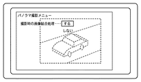
図6は、デジタルカメラ100によるパノラマ撮像時に画像データの結合を行うか否かをユーザに選択させるためのユーザインタフェースを示す図である。このインタフェースは、例えばユーザが操作部110を操作することにより呼び出されて表示部106に表示される。図に示すように、ユーザが結合処理を「する」を選択した場合、パノラマ撮像時に以下に示す処理が行われる。なお、ユーザが結合処理を「しない」を選択した場合、パノラマ撮像時に行われる処理は第1の実施形態と同様である。
<User interface>
FIG. 6 is a diagram showing a user interface for allowing the user to select whether or not to combine image data when panoramic imaging is performed by the
<パノラマ撮像処理の流れ>
図7は、第2の実施形態における、デジタルカメラ100を用いたパノラマ撮像処理の流れを示すフローチャートである。第1の実施形態(図2)と同一の処理を行うステップには同一の符号を付し、説明を省略する。
<Flow of panorama imaging process>
FIG. 7 is a flowchart illustrating a flow of panorama imaging processing using the
ステップS701で、制御部101は、N>1であるか否かを判定する。N>1の場合はステップS702に進み、N>1でない場合はステップS704に進む。
In step S701, the
ステップS702で、制御部101は、メモリカード109から1〜(N−1)番目の画像データから構成されるパノラマ画像データを取得し、RAM119に格納する。
In step S <b> 702, the
ステップS703で、制御部101は、ステップS702で取得したパノラマ画像データとN番目の画像データを結合し、新たなパノラマ画像データを生成する。パノラマ画像合成方法は、合成しようとする複数の画像の中から対応点を捜し出し、この対応点を元に合成処理を行う。
In step S703, the
ステップS704で、制御部101は、ステップS703で生成されたパノラマ画像データをメモリカード109に書き込む。ただし、N=1の場合、制御部101は1番目の画像データをメモリカード109に書き込む。
In step S704, the
ステップS705で、制御部101は、ステップS704でメモリカード109に記録した画像データの示す画像を、表示部106に表示する。
In step S705, the
<第2の実施形態のまとめ>
以上説明したように、本実施形態によれば、デジタルカメラ100が複数の画像データから1つのパノラマ画像ファイルを生成し、メモリカード109に記録する。
<Summary of Second Embodiment>
As described above, according to the present embodiment, the
これにより、ユーザがPC等で画像ファイルの結合処理を行う必要が無く、煩雑さが軽減される。 This eliminates the need for the user to perform image file combination processing on a PC or the like, thereby reducing complexity.
[第3の実施形態]
第1の実施形態では、パノラマ撮像時に、直前に撮像された画像と光学レンズ111が現在捉えている画像が、重なることなく表示部106に表示された。
[Third Embodiment]
In the first embodiment, at the time of panoramic imaging, the image captured immediately before and the image currently captured by the
第3の実施形態では、パノラマ撮像時に、光学レンズ111が現在捉えている画像が直前に撮像された画像の一部に重ねられて(オーバレイされて)表示部106に表示される構成を説明する。これにより、ユーザが複数の画像を隙間無く撮像することがより容易になる。
In the third embodiment, a configuration will be described in which an image currently captured by the
なお、本実施形態において、デジタルカメラ100の構成は第1の実施形態と同様でよいため、その説明を省略する。
In the present embodiment, the configuration of the
また、以下では、第3の実施形態における構成を第1の実施形態における構成に付加して説明するが、第2の実施形態における構成に付加することもできる。 In the following description, the configuration in the third embodiment is added to the configuration in the first embodiment, but may be added to the configuration in the second embodiment.
<ユーザインタフェース>
図8は、デジタルカメラ100によるパノラマ撮像時に画像データを重ねるか否かをユーザに選択させるためのユーザインタフェースを示す図である。このインタフェースは、例えばユーザが操作部110を操作することにより呼び出されて表示部106に表示される。図に示すように、ユーザが重なりを「小」又は「大」を選択した場合、パノラマ撮像時に以下に示す処理が行われる。なお、ユーザが重なりを「なし」を選択した場合、パノラマ撮像時に行われる処理は第1の実施形態と同様である。
<User interface>
FIG. 8 is a diagram showing a user interface for allowing the user to select whether or not to superimpose image data when panoramic imaging is performed by the
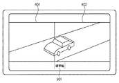
図9は、パノラマ撮像時に、光学レンズ111が現在捉えている画像が直前に撮像された画像の一部に重ねられて(オーバレイされて)表示部106に表示される様子を示す図である。図に示すように、第1の実施形態と異なり、表示領域402は境界幅901を持つ。境界幅901が、光学レンズ111が現在捉えている画像と直前に撮像された画像の重なり部分であり、幅の大きさは図8のユーザインタフェースを介して決定される。
FIG. 9 is a diagram illustrating a state in which the image currently captured by the
<パノラマ撮像処理の流れ>
図10は、第3の実施形態における、デジタルカメラ100を用いたパノラマ撮像処理の流れを示すフローチャートである。第1の実施形態(図2)と同一の処理を行うステップには同一の符号を付し、説明を省略する。
<Flow of panorama imaging process>
FIG. 10 is a flowchart illustrating a flow of panorama imaging processing using the
ステップS1001における処理は、ステップS206における処理と似ているが、表示部106に表示される画像が図5に示すものではなく、図9に示すものである。 The process in step S1001 is similar to the process in step S206, but the image displayed on the display unit 106 is not shown in FIG. 5 but shown in FIG.
ステップS1002で、制御部101は、ステップS208と同様、撮像を行い、N番目の画像データを取得する。ただし、N番目の画像データは、図9の表示領域402から境界幅901に表示される部分を除いた画像から生成されるものである。なお、N番目の画像データを取得する段階では境界幅901に表示される部分を除かず、パノラマ画像生成時に境界幅901に表示される部分を除いてももちろん構わない。
In step S1002, the
<第3の実施形態のまとめ>
以上説明したように、本実施形態によれば、パノラマ撮像時に、光学レンズ111が現在捉えている画像が直前に撮像された画像の一部に重ねられて(オーバレイされて)表示部106に表示される。
<Summary of Third Embodiment>
As described above, according to the present embodiment, at the time of panoramic imaging, the image currently captured by the
これにより、ユーザが複数の画像を隙間無く撮像することがより容易になる。 This makes it easier for the user to capture a plurality of images without gaps.
[第4の実施形態]
第1〜第3の実施形態では、パノラマ画像を構成する個々の画像のアスペクト比は必ず横4:縦3であるという前提で説明した。
[Fourth Embodiment]
In the first to third embodiments, the description has been made on the assumption that the aspect ratios of the individual images constituting the panoramic image are always 4: 3.
第4の実施形態では、パノラマ画像を構成する個々の画像のアスペクト比を横4:縦3とするか、横16:縦9とするかをユーザが選択可能な構成を示す。これにより、ユーザは横16:縦9のワイド画像を用いたパノラマ撮像も可能となり、より柔軟なパノラマ撮像が可能となる。 The fourth embodiment shows a configuration in which the user can select whether the aspect ratio of individual images constituting a panoramic image is horizontal 4: vertical 3 or horizontal 16: vertical 9. Accordingly, the user can perform panoramic imaging using a wide image of horizontal 16: vertical 9 and more flexible panoramic imaging is possible.
なお、本実施形態において、デジタルカメラ100の構成は第1の実施形態と同様でよいため、その説明を省略する。
In the present embodiment, the configuration of the
また、以下では、第4の実施形態における構成を第1の実施形態における構成に付加して説明するが、第2又は第3の実施形態における構成に付加することもできる。 In the following description, the configuration in the fourth embodiment is added to the configuration in the first embodiment, but may be added to the configuration in the second or third embodiment.
図11は、第4の実施形態における、デジタルカメラ100を用いたパノラマ撮像処理の流れを示すフローチャートである。第1の実施形態(図2)と同一の処理を行うステップには同一の符号を付し、説明を省略する。
FIG. 11 is a flowchart illustrating a flow of panoramic imaging processing using the
ステップS1101で、制御部101は、パノラマ画像を構成する個々の画像、すなわち撮像画像のアスペクト比が横16:縦9に設定されているか否かを判定する。ここでの判定は、制御部101が操作部110に含まれるスイッチ等の状態を検出することにより行われる。撮像画像のアスペクト比が横16:縦9に設定されていればステップS1102に進み、そうでなければステップS204に進む。
In step S1101, the
ステップS1102における処理は、ステップS204における処理と似ているが、表示部106に表示される画像のアスペクト比が横16:縦9である点が異なる。図12は、ステップS1102において表示部106に表示される画像の一例を示す図である。 The process in step S1102 is similar to the process in step S204, except that the aspect ratio of the image displayed on the display unit 106 is 16 (horizontal): 9 (vertical). FIG. 12 is a diagram illustrating an example of an image displayed on the display unit 106 in step S1102.
ステップS1103で、制御部101は、ステップS1101で判定されたアスペクト比でパノラマ撮像を行ってよいかをユーザが確認するためのユーザインタフェースを表示部106に表示する。そして、制御部101は、操作部110などを介してアスペクト比がユーザに了承されたか否かを判定する。図13は、ステップS1103において表示部106に表示されるユーザインタフェースの一例を示す図である。アスペクト比がユーザに了承された場合はステップS205に進み、そうでない場合はステップS1101に戻る。
In step S1103, the
<第4の実施形態のまとめ>
以上説明したように、本実施形態によれば、デジタルカメラ100を用いたパノラマ撮像において、パノラマ画像を構成する個々の画像のアスペクト比を横4:縦3とするか、横16:縦9とするかをユーザが選択可能である。
<Summary of Fourth Embodiment>
As described above, according to the present embodiment, in panoramic imaging using the
これにより、ユーザは横16:縦9のワイド画像を用いたパノラマ撮像も可能となり、より柔軟なパノラマ撮像が可能となる。 Accordingly, the user can perform panoramic imaging using a wide image of horizontal 16: vertical 9 and more flexible panoramic imaging is possible.
[その他の実施形態]
上述した各実施形態では、撮像画像を左から右へ順に並べてパノラマ画像とすることとしていた。しかし、撮像画像を右から左へ順に並べてパノラマ画像としてももちろん構わない。
[Other Embodiments]
In each embodiment described above, the captured images are arranged in order from left to right to form a panoramic image. However, of course, the captured images may be arranged in order from right to left to form a panoramic image.
また、上述した各実施の形態の処理は、各機能を具現化したソフトウェアのプログラムコードを記録した記憶媒体をシステム或は装置に提供してもよい。そして、そのシステム或は装置のコンピュータ(又はCPUやMPU)が記憶媒体に格納されたプログラムコードを読み出し実行することによって、前述した実施形態の機能を実現することができる。この場合、記憶媒体から読み出されたプログラムコード自体が前述した実施形態の機能を実現することになり、そのプログラムコードを記憶した記憶媒体は本発明を構成することになる。このようなプログラムコードを供給するための記憶媒体としては、例えば、フロッピィ(登録商標)ディスク、ハードディスク、光ディスク、光磁気ディスクなどを用いることができる。或いは、CD−ROM、CD−R、磁気テープ、不揮発性のメモリカード、ROMなどを用いることもできる。 In addition, the processing of each embodiment described above may provide a system or apparatus with a storage medium that records a program code of software that embodies each function. The functions of the above-described embodiments can be realized by the computer (or CPU or MPU) of the system or apparatus reading and executing the program code stored in the storage medium. In this case, the program code itself read from the storage medium realizes the functions of the above-described embodiments, and the storage medium storing the program code constitutes the present invention. As a storage medium for supplying such a program code, for example, a floppy (registered trademark) disk, a hard disk, an optical disk, a magneto-optical disk, or the like can be used. Alternatively, a CD-ROM, CD-R, magnetic tape, nonvolatile memory card, ROM, or the like can be used.
また、コンピュータが読み出したプログラムコードを実行することにより、前述した各実施の形態の機能が実現されるだけではない。そのプログラムコードの指示に基づき、コンピュータ上で稼動しているOS(オペレーティングシステム)などが実際の処理の一部又は全部を行い、その処理によって前述した各実施の形態の機能が実現される場合も含まれている。 The functions of the above-described embodiments are not only realized by executing the program code read by the computer. In some cases, an OS (operating system) running on the computer performs part or all of the actual processing based on the instruction of the program code, and the functions of the above-described embodiments are realized by the processing. include.
さらに、記憶媒体から読み出されたプログラムコードが、コンピュータに挿入された機能拡張ボードやコンピュータに接続された機能拡張ユニットに備わるメモリに書きこまれてもよい。その後、そのプログラムコードの指示に基づき、その機能拡張ボードや機能拡張ユニットに備わるCPUなどが実際の処理の一部又は全部を行い、その処理によって前述した各実施の形態の機能が実現される場合も含むものである。 Further, the program code read from the storage medium may be written in a memory provided in a function expansion board inserted into the computer or a function expansion unit connected to the computer. After that, the CPU of the function expansion board or function expansion unit performs part or all of the actual processing based on the instruction of the program code, and the functions of the above-described embodiments are realized by the processing. Is also included.
100 デジタルカメラ
106 表示部
100 Digital Camera 106 Display Unit
Claims (10)
前記撮像手段により取得された、複数の画像データから生成されたパノラマ画像データを取得するパノラマ画像取得手段と、
前記画像データ及び前記パノラマ画像データのうち少なくともいずれかを表示する表示手段と、
を備え、
前記表示手段のアスペクト比は横16:縦9であることを特徴とする撮像装置。 Imaging means for capturing and acquiring image data;
Panoramic image acquisition means for acquiring panoramic image data generated from a plurality of image data acquired by the imaging means;
Display means for displaying at least one of the image data and the panoramic image data;
With
The aspect ratio of the display means is horizontal 16: vertical 9;
前記撮像工程により取得された、複数の画像データから生成されたパノラマ画像データを取得するパノラマ画像取得工程と、
前記画像データ及び前記パノラマ画像データのうち少なくともいずれかを表示手段に表示する表示工程と、
を備え、
前記表示手段のアスペクト比は横16:縦9であることを特徴とする撮像方法。 An imaging step of imaging and obtaining image data;
A panoramic image acquisition step of acquiring panoramic image data generated from a plurality of image data acquired by the imaging step;
A display step of displaying at least one of the image data and the panoramic image data on a display means;
With
The imaging method according to claim 1, wherein the aspect ratio of the display means is 16: 9.
前記撮像工程により取得された、複数の画像データから生成されたパノラマ画像データを取得するパノラマ画像取得工程と、
前記画像データ及び前記パノラマ画像データのうち少なくともいずれかを表示手段に表示する表示工程と、
を備え、
前記表示手段のアスペクト比は横16:縦9であることを特徴とする撮像方法をコンピュータに実行させるためのプログラム。 An imaging step of imaging and obtaining image data;
A panoramic image acquisition step of acquiring panoramic image data generated from a plurality of image data acquired by the imaging step;
A display step of displaying at least one of the image data and the panoramic image data on a display means;
With
A program for causing a computer to execute an imaging method, wherein the display means has an aspect ratio of 16: 9.
Priority Applications (1)
| Application Number | Priority Date | Filing Date | Title |
|---|---|---|---|
| JP2005337491A JP2007143064A (en) | 2005-11-22 | 2005-11-22 | Imaging device and imaging method |
Applications Claiming Priority (1)
| Application Number | Priority Date | Filing Date | Title |
|---|---|---|---|
| JP2005337491A JP2007143064A (en) | 2005-11-22 | 2005-11-22 | Imaging device and imaging method |
Publications (2)
| Publication Number | Publication Date |
|---|---|
| JP2007143064A true JP2007143064A (en) | 2007-06-07 |
| JP2007143064A5 JP2007143064A5 (en) | 2009-01-08 |
Family
ID=38205331
Family Applications (1)
| Application Number | Title | Priority Date | Filing Date |
|---|---|---|---|
| JP2005337491A Pending JP2007143064A (en) | 2005-11-22 | 2005-11-22 | Imaging device and imaging method |
Country Status (1)
| Country | Link |
|---|---|
| JP (1) | JP2007143064A (en) |
Cited By (4)
| Publication number | Priority date | Publication date | Assignee | Title |
|---|---|---|---|---|
| JP2008011240A (en) * | 2006-06-29 | 2008-01-17 | Canon Inc | Imaging apparatus, control method, and computer program |
| JP2008017036A (en) * | 2006-07-04 | 2008-01-24 | Canon Inc | Imaging device and method of controlling the same, and computer program |
| JP2009094726A (en) * | 2007-10-05 | 2009-04-30 | Fujifilm Corp | Image recording apparatus and image recording method |
| JP2014236311A (en) * | 2013-05-31 | 2014-12-15 | キヤノン株式会社 | Image processing apparatus, image processing method, and program |
Citations (14)
| Publication number | Priority date | Publication date | Assignee | Title |
|---|---|---|---|---|
| JPH02178646A (en) * | 1988-12-29 | 1990-07-11 | Canon Inc | Panoramic photographing device |
| JPH05183790A (en) * | 1992-01-07 | 1993-07-23 | Canon Inc | Electronic still camera |
| JPH05191769A (en) * | 1992-01-16 | 1993-07-30 | Canon Inc | Picture recorder |
| JPH0730788A (en) * | 1993-07-07 | 1995-01-31 | Ricoh Co Ltd | Video camera apparatus |
| JPH0832871A (en) * | 1994-07-15 | 1996-02-02 | Canon Inc | Compound-eye image pickup device and compound-eye image pickup recording and reproducing device |
| JPH08317324A (en) * | 1995-05-15 | 1996-11-29 | Canon Inc | Electronic camera |
| JPH095868A (en) * | 1995-06-21 | 1997-01-10 | Minolta Co Ltd | Image photographic device |
| JPH09289598A (en) * | 1996-04-22 | 1997-11-04 | Canon Inc | Display device |
| JPH09322054A (en) * | 1996-05-28 | 1997-12-12 | Canon Inc | Electronic camera system |
| JPH09322055A (en) * | 1996-05-28 | 1997-12-12 | Canon Inc | Electronic camera system |
| JPH10155109A (en) * | 1996-11-22 | 1998-06-09 | Canon Inc | Image pickup method, device and storage medium |
| JPH1188747A (en) * | 1997-09-12 | 1999-03-30 | Canon Inc | Photographing device, printer device and photographing system |
| JPH11261939A (en) * | 1998-03-11 | 1999-09-24 | Canon Inc | Image processing method, its unit and storage medium |
| JP2003189153A (en) * | 2001-12-14 | 2003-07-04 | Canon Inc | Image pickup device, panorama image display method, stereoscopic image display method, method for displaying panorama image/stereoscopic image, and storage medium |
-
2005
- 2005-11-22 JP JP2005337491A patent/JP2007143064A/en active Pending
Patent Citations (14)
| Publication number | Priority date | Publication date | Assignee | Title |
|---|---|---|---|---|
| JPH02178646A (en) * | 1988-12-29 | 1990-07-11 | Canon Inc | Panoramic photographing device |
| JPH05183790A (en) * | 1992-01-07 | 1993-07-23 | Canon Inc | Electronic still camera |
| JPH05191769A (en) * | 1992-01-16 | 1993-07-30 | Canon Inc | Picture recorder |
| JPH0730788A (en) * | 1993-07-07 | 1995-01-31 | Ricoh Co Ltd | Video camera apparatus |
| JPH0832871A (en) * | 1994-07-15 | 1996-02-02 | Canon Inc | Compound-eye image pickup device and compound-eye image pickup recording and reproducing device |
| JPH08317324A (en) * | 1995-05-15 | 1996-11-29 | Canon Inc | Electronic camera |
| JPH095868A (en) * | 1995-06-21 | 1997-01-10 | Minolta Co Ltd | Image photographic device |
| JPH09289598A (en) * | 1996-04-22 | 1997-11-04 | Canon Inc | Display device |
| JPH09322054A (en) * | 1996-05-28 | 1997-12-12 | Canon Inc | Electronic camera system |
| JPH09322055A (en) * | 1996-05-28 | 1997-12-12 | Canon Inc | Electronic camera system |
| JPH10155109A (en) * | 1996-11-22 | 1998-06-09 | Canon Inc | Image pickup method, device and storage medium |
| JPH1188747A (en) * | 1997-09-12 | 1999-03-30 | Canon Inc | Photographing device, printer device and photographing system |
| JPH11261939A (en) * | 1998-03-11 | 1999-09-24 | Canon Inc | Image processing method, its unit and storage medium |
| JP2003189153A (en) * | 2001-12-14 | 2003-07-04 | Canon Inc | Image pickup device, panorama image display method, stereoscopic image display method, method for displaying panorama image/stereoscopic image, and storage medium |
Cited By (7)
| Publication number | Priority date | Publication date | Assignee | Title |
|---|---|---|---|---|
| JP2008011240A (en) * | 2006-06-29 | 2008-01-17 | Canon Inc | Imaging apparatus, control method, and computer program |
| JP4557927B2 (en) * | 2006-06-29 | 2010-10-06 | キヤノン株式会社 | Imaging apparatus, control method, and computer program |
| JP2008017036A (en) * | 2006-07-04 | 2008-01-24 | Canon Inc | Imaging device and method of controlling the same, and computer program |
| JP4557929B2 (en) * | 2006-07-04 | 2010-10-06 | キヤノン株式会社 | IMAGING DEVICE, IMAGING DEVICE CONTROL METHOD, AND COMPUTER PROGRAM |
| JP2009094726A (en) * | 2007-10-05 | 2009-04-30 | Fujifilm Corp | Image recording apparatus and image recording method |
| US8243121B2 (en) | 2007-10-05 | 2012-08-14 | Fujifilm Corporation | Image recording apparatus and image recording method |
| JP2014236311A (en) * | 2013-05-31 | 2014-12-15 | キヤノン株式会社 | Image processing apparatus, image processing method, and program |
Similar Documents
| Publication | Publication Date | Title |
|---|---|---|
| EP1791357B1 (en) | Recording device and method, recording and reproduction device and method, and program | |
| US20030052986A1 (en) | Image processing apparatus, image processing method, program, and storage medium | |
| JP2008206138A (en) | Imaging apparatus and image processor | |
| JP2007195050A (en) | Imaging device and method, and control program | |
| JP2004120069A (en) | Image processing apparatus, image processing method, and program for realizing the method | |
| JP4734679B2 (en) | Image processing apparatus, method, and program | |
| JP2008258981A (en) | Imaging apparatus, control method thereof, program | |
| JP4652210B2 (en) | Image data output control device | |
| JP2007143064A (en) | Imaging device and imaging method | |
| JP2011077654A (en) | Imaging apparatus, control method thereof and program | |
| US7855734B2 (en) | Image processing apparatus, control method thereof, program, and storage medium | |
| JP2005094298A (en) | Digital camera and image data recording method | |
| JP2007036587A (en) | Imaging apparatus and its control method | |
| JP2004312463A (en) | Image regenerating method | |
| JP2009225212A (en) | Image pickup device and image storing method | |
| JP4025525B2 (en) | Electronic camera | |
| JP5067872B2 (en) | Image reproduction apparatus, control method thereof, and program | |
| JP2008182339A (en) | Image processor, image processing method, and computer program | |
| JP2008099147A (en) | Image processor and image processing method | |
| JP2006287588A (en) | Image processing apparatus and method, data file structure, computer program, and storage medium | |
| JP4646723B2 (en) | Image reproduction apparatus, imaging apparatus, and control method | |
| JP6857863B1 (en) | Imaging device and recording method of image data | |
| JP2001111920A (en) | Image recorder and image recording method | |
| JP4766706B2 (en) | Image processing apparatus, control method therefor, program, and storage medium | |
| JP2007166024A (en) | Imaging apparatus and control method thereof |
Legal Events
| Date | Code | Title | Description |
|---|---|---|---|
| A521 | Request for written amendment filed |
Free format text: JAPANESE INTERMEDIATE CODE: A523 Effective date: 20081113 |
|
| A621 | Written request for application examination |
Free format text: JAPANESE INTERMEDIATE CODE: A621 Effective date: 20081113 |
|
| A131 | Notification of reasons for refusal |
Free format text: JAPANESE INTERMEDIATE CODE: A131 Effective date: 20100305 |
|
| A521 | Request for written amendment filed |
Free format text: JAPANESE INTERMEDIATE CODE: A523 Effective date: 20100423 |
|
| A131 | Notification of reasons for refusal |
Free format text: JAPANESE INTERMEDIATE CODE: A131 Effective date: 20100521 |
|
| A521 | Request for written amendment filed |
Free format text: JAPANESE INTERMEDIATE CODE: A523 Effective date: 20100630 |
|
| A131 | Notification of reasons for refusal |
Free format text: JAPANESE INTERMEDIATE CODE: A131 Effective date: 20100809 |
|
| A521 | Request for written amendment filed |
Free format text: JAPANESE INTERMEDIATE CODE: A523 Effective date: 20100916 |
|
| A131 | Notification of reasons for refusal |
Free format text: JAPANESE INTERMEDIATE CODE: A131 Effective date: 20101115 |
|
| A521 | Request for written amendment filed |
Free format text: JAPANESE INTERMEDIATE CODE: A523 Effective date: 20110107 |
|
| A02 | Decision of refusal |
Free format text: JAPANESE INTERMEDIATE CODE: A02 Effective date: 20110308 |


