JP2007123771A - Door shell carrier and door shell carrying method - Google Patents
Door shell carrier and door shell carrying method Download PDFInfo
- Publication number
- JP2007123771A JP2007123771A JP2005317453A JP2005317453A JP2007123771A JP 2007123771 A JP2007123771 A JP 2007123771A JP 2005317453 A JP2005317453 A JP 2005317453A JP 2005317453 A JP2005317453 A JP 2005317453A JP 2007123771 A JP2007123771 A JP 2007123771A
- Authority
- JP
- Japan
- Prior art keywords
- door shell
- shell
- tank
- door
- pod
- Prior art date
- Legal status (The legal status is an assumption and is not a legal conclusion. Google has not performed a legal analysis and makes no representation as to the accuracy of the status listed.)
- Withdrawn
Links
- 238000000034 method Methods 0.000 title claims description 21
- 238000001035 drying Methods 0.000 claims description 93
- 238000004140 cleaning Methods 0.000 claims description 88
- 238000012546 transfer Methods 0.000 claims description 24
- 230000032258 transport Effects 0.000 claims description 21
- 238000000926 separation method Methods 0.000 claims description 19
- 230000005484 gravity Effects 0.000 claims description 12
- 238000012545 processing Methods 0.000 claims description 4
- XLYOFNOQVPJJNP-UHFFFAOYSA-N water Substances O XLYOFNOQVPJJNP-UHFFFAOYSA-N 0.000 abstract description 30
- 239000000126 substance Substances 0.000 abstract description 21
- 239000007788 liquid Substances 0.000 abstract 1
- 238000005406 washing Methods 0.000 description 16
- 235000012431 wafers Nutrition 0.000 description 6
- 238000011109 contamination Methods 0.000 description 4
- 238000004519 manufacturing process Methods 0.000 description 4
- 238000005507 spraying Methods 0.000 description 4
- 238000007664 blowing Methods 0.000 description 3
- 230000003749 cleanliness Effects 0.000 description 3
- 230000003028 elevating effect Effects 0.000 description 3
- 239000002184 metal Substances 0.000 description 3
- 238000012856 packing Methods 0.000 description 3
- 238000007602 hot air drying Methods 0.000 description 2
- 239000004065 semiconductor Substances 0.000 description 2
- 238000004506 ultrasonic cleaning Methods 0.000 description 2
- 238000011161 development Methods 0.000 description 1
- 238000010438 heat treatment Methods 0.000 description 1
- 238000012986 modification Methods 0.000 description 1
- 230000004048 modification Effects 0.000 description 1
- 238000003032 molecular docking Methods 0.000 description 1
- 239000002245 particle Substances 0.000 description 1
- 239000000758 substrate Substances 0.000 description 1
Images
Landscapes
- Container, Conveyance, Adherence, Positioning, Of Wafer (AREA)
- Cleaning Or Drying Semiconductors (AREA)
Abstract
Description
本発明は、ドアシェル搬送機及びドアシェル搬送方法に係わり、特に、搬送時に純水や薬液が垂れることを抑制できるドアシェル搬送機及びドアシェル搬送方法に関する。 The present invention relates to a door shell transporter and a door shell transport method, and more particularly, to a door shell transporter and a door shell transport method that can suppress dripping of pure water or chemicals during transport.
半導体の製造は多数の工程を極めて高いクリーン度のもとで行わなければならないが、全ての工程におよぶ広大な環境を高いクリーン度に保つのはコスト面で限界がある。このため、局所環境(ミニ・エンバイロメント)だけを高いクリーン度に保つ手段の開発が進められている。例えば、ウエハをFOUP(Front Opening Unified Pod)と呼ばれる密閉型容器で搬送し、密閉型容器ごとウエハを半導体製造工程に入れ、密閉型容器を直接製造装置とドッキングさせて作業を進めるもので、密閉型容器内部の環境を管理することで製造工程内におけるウエハの高いクリーン度を維持することができることになる。 Semiconductor manufacturing requires many processes to be performed under a very high degree of cleanness, but there is a limit in terms of cost to keep a large environment in all processes at a high degree of cleanliness. For this reason, development of means for keeping only the local environment (mini-environment) at a high degree of cleanliness is underway. For example, a wafer is transported in a sealed container called FOUP (Front Opening Unified Pod), the wafer is put into the semiconductor manufacturing process together with the sealed container, and the work is performed by directly docking the sealed container with the manufacturing equipment. By managing the environment inside the mold container, it is possible to maintain a high degree of cleanness of the wafer in the manufacturing process.
ところで、このような密閉型容器は、多数のウエハを収納して搬送するのであるが、その際にウエハと容器内面とが擦れて内部にパーティクル等の汚れが生じ、また容器はクリーン度の低いところを移送されるため外面が汚染され易く、蓋を外したときに内部に収納したウエハを汚染するおそれがある。そこで、容器を定期的に洗浄する必要がある。 By the way, such a sealed container accommodates and transports a large number of wafers. At that time, the wafer and the inner surface of the container are rubbed to cause contamination such as particles, and the container has a low cleanliness. However, since it is transferred, the outer surface is easily contaminated, and when the lid is removed, the wafer housed inside may be contaminated. Therefore, it is necessary to periodically clean the container.
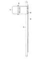
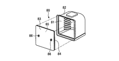
図10に示すように、FOUP80は、その前面に開口部81を有して基板を水平状態で収納する容器本体であるポッドシェル82と、開口部81をシール可能に閉鎖してポッドシェル82に係合する蓋体であるドアシェル83を備えたものである。尚、ドアシェル83は、開口部81をシール可能に閉鎖するためのパッキン84を備えている。
ドアシェル83とポッドシェル82を結合して組み立てる際は、ドアシェルの内面85がポッドシェルの内面に対向するように設置し、ロック部(留め具)86によってドアシェルとポッドシェルを留めることでFOUPとする。FOUP80は必要に応じて、ポッドシェル82とドアシェル83に分解されて、それぞれ別々に洗浄される。
As shown in FIG. 10, the FOUP 80 has a
When the
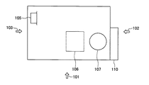
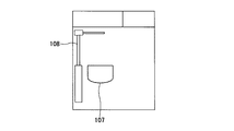
図11は、従来のFOUP洗浄乾燥装置を模式的に示す上面図である。図12は、図11に示す矢印101の方向から視たFOUP洗浄乾燥装置の側面図である。図13は、図11に示す矢印102の方向から視たFOUP洗浄乾燥装置の側面図である。図14は、図11に示す矢印103の方向から視たFOUP洗浄乾燥装置の側面図である。
FIG. 11 is a top view schematically showing a conventional FOUP cleaning / drying apparatus. 12 is a side view of the FOUP cleaning / drying apparatus viewed from the direction of the
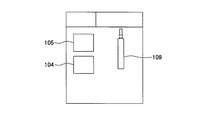
図11〜図14に示すように、従来のFOUP洗浄乾燥装置は、ドアシェル洗浄槽104、ドアシェル乾燥槽105、ポッドシェル洗浄槽106、ポッドシェル乾燥槽107、ポッドシェル搬送機108、ドアシェル搬送機109、電装ボックス110及びクリーンユニット111を有している。
As shown in FIGS. 11 to 14, the conventional FOUP cleaning and drying apparatus includes a door
まず、ポッドシェルの洗浄方法について説明する。開口部を下に向けたポッドシェルをポッドシェル洗浄槽106内に収容し、ポッドシェル洗浄槽106に洗浄用の純水を導入しながらポッドシェル内の空気を排気する。これにより、開口部からポッドシェルの内部に純水が効率よく導入されつつ洗浄槽106内も純水で満たされ、ポッドシェルが洗浄槽内の洗浄水に浸漬される。次に、ポッドシェル及び洗浄水に超音波振動を印加することにより超音波洗浄が行われる。
First, a method for cleaning the pod shell will be described. The pod shell with the opening facing downward is accommodated in the pod
次に、ポッドシェルの乾燥方法について説明する。ポッドシェル洗浄槽106によって洗浄されたポッドシェルを、ポッドシェル搬送機108によってポッドシェル乾燥槽107に搬送し、乾燥槽107内に収容する。次いで、ポッドシェル乾燥槽107において、洗浄後のポッドシェルの外側面及び内面に熱風を吹きかけて熱風乾燥を行う。所定時間乾燥させた後、ポッドシェル乾燥槽内を減圧して減圧乾燥を行う。所定時間減圧した後、ポッドシェル乾燥槽を大気開放し、常圧に戻してから再び熱風乾燥及び減圧乾燥を繰り返す。(例えば特許文献1参照)。
Next, a method for drying the pod shell will be described. The pod shell cleaned by the pod
次に、ドアシェルの洗浄方法について説明する。ドアシェルの内面をドアシェル洗浄槽104側に向けて固定し、ドアシェルの内面に洗浄用の純水を吹き付ける。これにより、ドアシェルの内面、パッキン及びその近傍が洗浄される。
Next, a method for cleaning the door shell will be described. The inner surface of the door shell is fixed toward the door
次に、洗浄後のドアシェルを、ドアシェル搬送機109によってドアシェル洗浄槽104からドアシェル乾燥槽105に搬送する。次いで、ドアシェル乾燥槽105において、ドアシェルの内面に清浄な高圧空気を吹き付け、ドアシェルの内面に付着して残っていた純水を吹き飛ばして除去する(例えば特許文献2参照)。その他のドアシェルの乾燥方式として、空気を加熱して乾燥させる熱風発生器を用いた熱風乾燥なども用いられている。
Next, the washed door shell is transferred from the door
ところで、従来のFOUP洗浄乾燥装置では、ポッドシェル及びドアシェルそれぞれの洗浄を純水によって行っているため、金属による汚れを除去することが困難である。また、従来のドアシェル洗浄槽において金属による汚れを除去するために薬液を用いた場合、ドアシェルを垂直に立てた状態でドアシェル搬送機109によってドアシェル洗浄槽104からドアシェル乾燥槽105に搬送しているため、この搬送時にドアシェルに付着した薬液が垂れてしまい、FOUP洗浄乾燥装置が薬液で汚染されてしまう。
By the way, in the conventional FOUP cleaning / drying apparatus, each of the pod shell and the door shell is cleaned with pure water, so it is difficult to remove metal contamination. In addition, when a chemical solution is used to remove metal contamination in a conventional door shell cleaning tank, the door shell is transferred from the door
本発明は上記のような事情を考慮してなされたものであり、その目的は、搬送時に純水や薬液が垂れることを抑制できるドアシェル搬送機及びドアシェル搬送方法を提供することにある。 The present invention has been made in view of the above circumstances, and an object of the present invention is to provide a door shell transporter and a door shell transport method capable of suppressing dripping of pure water or chemicals during transport.
上記課題を解決するため、本発明に係るドアシェル搬送機は、ドアシェルを搬送するドアシェル搬送機において、
FOUPにおいてポッドシェルからドアシェルを分離する分離機能を有するとともに前記ドアシェルを保持する保持機能を有する分離保持機構と、
前記分離保持機構を回転させる回転機構と、
を具備することを特徴とする。
In order to solve the above problems, a door shell transporter according to the present invention is a door shell transporter that transports a door shell.
A separation holding mechanism having a separation function of separating the door shell from the pod shell in the FOUP and a holding function of holding the door shell;
A rotating mechanism for rotating the separation holding mechanism;
It is characterized by comprising.
また、本発明に係るドアシェル搬送機において、前記ポッドシェルから前記ドアシェルを分離する際に前記分離保持機構によって保持されたドアシェルの内面は重力方向に対して略逆方向を向き、前記分離した後に前記分離保持機構によって保持されたドアシェルの内面は略重力方向を向くように、前記回転機構を制御する制御部をさらに具備することが好ましい。 Further, in the door shell conveyor according to the present invention, the inner surface of the door shell held by the separation holding mechanism when separating the door shell from the pod shell is directed in a substantially opposite direction with respect to the direction of gravity, and after the separation, It is preferable to further include a control unit that controls the rotation mechanism so that the inner surface of the door shell held by the separation and holding mechanism faces a substantially gravitational direction.
また、本発明に係るドアシェル搬送機において、前記分離保持機構を昇降させる昇降機構と、前記分離保持機構を略水平方向に移動させる移動機構と、をさらに具備することが好ましい。 The door shell transporter according to the present invention preferably further includes an elevating mechanism that moves the separation holding mechanism up and down and a moving mechanism that moves the separation holding mechanism in a substantially horizontal direction.
また、本発明に係るドアシェル搬送機において、前記移動機構は、前記回転機構が収容された筐体と、前記筐体に取り付けられたガイドと、前記ガイドが自在に移動できるガイドレールと、前記筐体に連結されたベルトと、前記ベルトを動かす駆動機構と、を具備することも可能である。 In the door shell conveyor according to the present invention, the moving mechanism includes a casing in which the rotating mechanism is accommodated, a guide attached to the casing, a guide rail in which the guide can freely move, and the casing. It is also possible to comprise a belt connected to the body and a drive mechanism for moving the belt.
また、本発明に係るドアシェル搬送機において、前記回転機構は、前記分離保持機構が回転軸を介して取り付けられたロータリーアクチュエーターを有することも可能である。 Moreover, the door shell conveyance machine which concerns on this invention WHEREIN: The said rotation mechanism can also have the rotary actuator to which the said separation holding mechanism was attached via the rotating shaft.
本発明に係るドアシェル搬送方法は、ドアシェルの内面が重力方向に対して略逆方向を向いた状態のFOUPにおいてポッドシェルからドアシェルを分離し、
前記分離したドアシェルを略180°回転させることにより、前記ドアシェルの内面を略重力方向に向かせ、
前記ドアシェルの内面を略重力方向に向かせた状態で該ドアシェルを処理槽に設置することを特徴とする。
In the door shell transport method according to the present invention, the door shell is separated from the pod shell in the FOUP in a state where the inner surface of the door shell faces in a direction substantially opposite to the direction of gravity.
By rotating the separated door shell by approximately 180 °, the inner surface of the door shell is directed in the direction of gravity,
The door shell is installed in the treatment tank in a state where the inner surface of the door shell is directed substantially in the direction of gravity.
本発明に係るドアシェル搬送方法は、ドアシェルの内面が略重力方向に向いた状態で処理槽に設置された前記ドアシェルを前記処理槽から上昇させ、
前記ドアシェルを略180°回転させることにより、前記ドアシェルの内面を重力方向と略逆方向に向かせ、
前記略逆方向を向いた状態の前記ドアシェルにポッドシェルを結合させてFOUPを組み立てることを特徴とする。
The door shell conveying method according to the present invention raises the door shell installed in the processing tank in a state where the inner surface of the door shell is substantially in the direction of gravity, from the processing tank,
By rotating the door shell approximately 180 °, the inner surface of the door shell is directed in a direction substantially opposite to the direction of gravity,
A FOUP is assembled by connecting a pod shell to the door shell in the substantially opposite direction.
また、本発明に係るドアシェル搬送方法において、前記処理槽は、ドアシェル洗浄リンス槽、ドアシェル水切り槽及びドアシェル乾燥槽のいずれかであることが好ましい。 Moreover, in the door shell conveying method according to the present invention, it is preferable that the processing tank is any one of a door shell cleaning rinse tank, a door shell draining tank, and a door shell drying tank.
以上説明したように本発明によれば、搬送時に純水や薬液が垂れることを抑制できるドアシェル搬送機及びドアシェル搬送方法を提供することができる。 As described above, according to the present invention, it is possible to provide a door shell transporter and a door shell transport method that can suppress dripping of pure water or chemicals during transport.
以下、図面を参照して本発明の実施の形態について説明する。
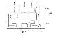
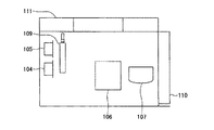
図1は、本発明の実施の形態によるFOUP洗浄乾燥装置を模式的に示す上面図である。図2は、図1に示す矢印21の方向から視たFOUP洗浄乾燥装置の側面図である。図3は、図1に示す矢印22の方向から視たFOUP洗浄乾燥装置の側面図である。
Embodiments of the present invention will be described below with reference to the drawings.
FIG. 1 is a top view schematically showing a FOUP cleaning / drying apparatus according to an embodiment of the present invention. FIG. 2 is a side view of the FOUP cleaning / drying apparatus viewed from the direction of the
図1に示すように、FOUP洗浄乾燥装置はドアシェル洗浄リンス槽1を有しており、このドアシェル洗浄リンス槽1の隣にはドアシェル水切り槽2が配置されている。このドアシェル水切り槽2の隣にはドアシェル乾燥槽3が配置されている。これら洗浄リンス槽1、水切り槽2及び乾燥槽3は横一列に配置されており、洗浄しようとするドアシェルをドアシェル搬送機8によって洗浄リンス槽1、水切り槽2及び乾燥槽3の相互間を搬送されるように構成されている。
As shown in FIG. 1, the FOUP cleaning / drying apparatus has a door shell cleaning rinse tank 1, and a door shell draining
前記ドアシェル洗浄リンス槽1は、ドアシェルを薬液で洗浄し純水でリンスする槽である。前記ドアシェル水切り槽2は、洗浄後のドアシェルの水切りを行う槽である。前記ドアシェル乾燥槽3は、水切り後のドアシェルの乾燥を行う槽である。
The door shell cleaning rinsing tank 1 is a tank for cleaning the door shell with a chemical solution and rinsing with pure water. The door
また、FOUP洗浄乾燥装置はポッドシェル洗浄槽4を有しており、このポッドシェル洗浄槽4はドアシェル洗浄リンス槽1に対向する位置に配されている。ポッドシェル洗浄槽4の隣にはポッドシェル水切り槽5が配置されており、このポッドシェル水切り槽5はドアシェル水切り槽2に対向する位置に配されている。ポッドシェル水切り槽5の隣にはポッドシェル乾燥槽6が配置されており、このポッドシェル乾燥槽6はドアシェル乾燥槽3に対向する位置に配されている。これら洗浄槽4、水切り槽5及び乾燥槽6は横一列に配置されており、洗浄しようとするポッドシェルをポッドシェル搬送機7によって洗浄槽4、水切り槽5及び乾燥槽6の相互間を搬送されるように構成されている。
Further, the FOUP cleaning / drying apparatus has a pod shell cleaning tank 4, and this pod shell cleaning tank 4 is arranged at a position facing the door shell cleaning rinse tank 1. Next to the pod shell washing tank 4, a pod shell draining tank 5 is arranged, and this pod shell draining tank 5 is arranged at a position facing the door
前記ポッドシェル洗浄槽4は、ポッドシェルを薬液で洗浄し純水でリンスする槽である。前記ポッドシェル水切り槽5は、洗浄後のポッドシェルの水切りを行う槽である。前記ポッドシェル乾燥槽6は、水切り後のポッドシェルの乾燥を行う槽である。 The pod shell cleaning tank 4 is a tank for cleaning the pod shell with a chemical solution and rinsing with pure water. The pod shell draining tank 5 is a tank for draining the washed pod shell. The pod shell drying tank 6 is a tank for drying the pod shell after draining.
また、FOUP洗浄乾燥装置は二つのドアシェル槽−ポッドシェル槽間搬送機9を有しており、一方の搬送機9はドアシェル洗浄リンス槽1とポッドシェル洗浄槽4との間のドアシェル又はポッドシェルの搬送を行うものであり、他方の搬送機9はドアシェル乾燥機3とポッドシェル乾燥機6との間のドアシェル又はポッドシェルの搬送を行うものである。
The FOUP cleaning / drying apparatus has two door shell tank-pod shell
ドアシェル搬送機8には、洗浄しようとするFOUPをドアシェルとポッドシェルに分解する分解手段(図示せず)及び洗浄が終了したポッドシェルとドアシェルを結合させてFOUPを組み立てる組み立て手段(図示せず)が設けられている。なお、ドアシェル搬送機8の詳細については後述する。 The door shell transporter 8 includes a disassembling means (not shown) for disassembling the FOUP to be cleaned into a door shell and a pod shell, and an assembling means (not shown) for assembling the FOUP by combining the cleaned pod shell and door shell. Is provided. The details of the door shell conveyor 8 will be described later.
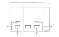
FOUP洗浄乾燥装置は薬液供給ユニット10を備えており、この薬液供給ユニット10は、ドアシェル洗浄リンス槽1及びポッドシェル洗浄槽4それぞれに薬液を供給するものである。また、FOUP洗浄乾燥装置は各槽及び各搬送機などに電力を供給する電源ボックス11を有している。また、FOUP洗浄乾燥装置は、図2に示すように該装置内の雰囲気をクリーンにするクリーンユニット12を有している。
The FOUP cleaning / drying apparatus includes a chemical
次に、図1〜図3に示すFOUP洗浄乾燥装置を用いたFOUP洗浄乾燥方法について説明する。
まず、洗浄しようとするFOUPを用意し、このFOUPを分解手段によりドアシェルとポッドシェルに分解する。詳細には、ドアシェルとポッドシェルを結合している留め具を外してドアシェルとポッドシェルを分解する。
Next, a FOUP cleaning / drying method using the FOUP cleaning / drying apparatus shown in FIGS. 1 to 3 will be described.
First, a FOUP to be cleaned is prepared, and this FOUP is decomposed into a door shell and a pod shell by a disassembling means. Specifically, the door shell and the pod shell are disassembled by removing the fasteners connecting the door shell and the pod shell.
次いで、ドアシェル搬送機8によってドアシェルの内面を下に向けて該ドアシェルをドアシェル洗浄リンス槽1に設置し、ドアシェル槽−ポッドシェル槽間搬送機9によってポッドシェルの開口部を下に向けて該ポッドシェルをポッドシェル洗浄槽4内に搬送する。
Subsequently, the door shell is placed in the door shell cleaning rinse tank 1 with the door shell conveyor 8 facing the inner surface of the door shell downward, and the pod shell opening is directed downward by the door shell tank-pod
次に、ドアシェル洗浄リンス槽1においてドアシェルの内面に薬液を吹き付けることにより該ドアシェルを薬液で洗浄し、この後、ドアシェルの内面に純水を吹き付けることにより該ドアシェルを純水でリンスする。また、ポッドシェル洗浄槽4においてポッドシェルを回転させながらポッドシェルの内面に薬液を吹き付けることにより該ポッドシェルを薬液で洗浄し、この後、ポッドシェルを回転させながらポッドシェルの内面に純水を吹き付けることにより該ポッドシェルを純水でリンスする。ポッドシェルを回転させることにより、ポッドシェルの内面に純水をむら無く吹き付けることができる。また、ポッドシェル内面に純水を吹き付ける方法を採用することにより、従来技術のように純水に浸漬させるのに比べて純水使用量を少なくすることができる。 Next, in the door shell cleaning rinsing tank 1, the door shell is cleaned with the chemical by spraying the chemical on the inner surface of the door shell, and then the door shell is rinsed with pure water by spraying pure water on the inner surface of the door shell. In addition, the pod shell cleaning tank 4 cleans the pod shell with a chemical solution by spraying the chemical solution onto the inner surface of the pod shell while rotating the pod shell. After that, pure water is applied to the inner surface of the pod shell while rotating the pod shell. The pod shell is rinsed with pure water by spraying. By rotating the pod shell, pure water can be sprayed evenly on the inner surface of the pod shell. Further, by adopting a method in which pure water is sprayed on the inner surface of the pod shell, the amount of pure water used can be reduced as compared with the case of immersing in pure water as in the prior art.
次いで、洗浄リンス後のドアシェルをドアシェル搬送機8によってドアシェル洗浄リンス槽1からドアシェル水切り槽2に搬送する。次いで、ドアシェル水切り槽2においてドアシェルにエアーなどの気体を吹き付けることによりドアシェルの内面に付着して残っていた純水を吹き飛ばして水を切る。また、洗浄リンス後のポッドシェルをポッドシェル搬送機7によってポッドシェル洗浄槽4からポッドシェル水切り槽5に搬送する。次いで、ポッドシェル水切り槽5においてポッドシェルを回転させるながらエアーなどの気体を吹き付けることによりポッドシェルに付着して残っていた純水を飛ばして水を切る。
Next, the door shell after the cleaning rinse is transferred from the door shell cleaning rinse tank 1 to the door
次に、水切り後のドアシェルをドアシェル搬送機8によってドアシェル水切り槽2からドアシェル乾燥槽3に搬送する。次いで、ドアシェル乾燥槽3においてドアシェルに熱風を吹き付けて該ドアシェルを乾燥させる。また、水切り後のポッドシェルをポッドシェル搬送機7によってポッドシェル水切り槽5からポッドシェル乾燥槽6に搬送する。次いで、ポッドシェル乾燥槽6においてポッドシェルに加熱エアーを吹き付けて遠心乾燥させる。遠心乾燥の回転速度はおよそ600rpmである。
Next, the door shell after draining is conveyed from the door
次いで、乾燥後のポッドシェルをドアシェル槽−ポッドシェル槽間搬送機9によってポッドシェル乾燥槽6からドアシェル乾燥槽3の上方又は近傍に搬送し、乾燥後のドアシェルをドアシェル搬送機8によってドアシェル乾燥槽3の上方又は近傍に搬送する。次いで、組み立て手段により前記ドアシェルと前記ポッドシェルを留め具によって結合してFOUPを組み立てる。
Next, the dried pod shell is transported from the pod shell drying tank 6 to the upper part of the door shell drying tank 3 or near the door shell drying tank 3 by the door shell tank-pod shell
上記実施の形態によれば、ドアシェル洗浄リンス槽1によってドアシェルを薬液で洗浄でき、ポッドシェル洗浄槽4によってポッドシェルを薬液で洗浄することができる。従って、従来技術では困難であった金属による汚れを除去することができる。 According to the above embodiment, the door shell can be cleaned with the chemical by the door shell cleaning rinse tank 1, and the pod shell can be cleaned with the chemical by the pod shell cleaning tank 4. Therefore, it is possible to remove metal contamination which has been difficult with the prior art.
また、本実施の形態では、ドアシェル洗浄リンス槽1、ドアシェル水切り槽2及びドアシェル乾燥槽3を横一列に配置し、ポッドシェル洗浄槽4、ポッドシェル水切り槽5及びポッドシェル乾燥槽6を横一列に配置し、ドアシェル洗浄リンス槽1をポッドシェル洗浄槽4と対向して配置し、ドアシェル水切り槽2をポッドシェル水切り槽5と対向して配置し、ドアシェル乾燥槽3をポッドシェル乾燥槽6と対向して配置している。このように配置することにより、分解後のドアシェルの洗浄、リンス、水切り及び乾燥と分解後のポッドシェルの洗浄、リンス、水切り及び乾燥を無駄な動作無く平行して行うことができる。従って、装置を小フットプリントで小型化することができるとともに装置のスループットを向上させることができる。
In this embodiment, the door shell cleaning rinse tank 1, the door
また、従来技術のようにポッドシェルを純水に浸漬させて超音波洗浄する方法を採らないため、従来技術に比べて洗浄時間を短縮することができる。つまり、従来技術では純水の給排水に時間がかかってしまい、スループットを向上させることが困難であったが、本実施の形態では洗浄時間を短縮することができる。 In addition, since the method of ultrasonic cleaning by immersing the pod shell in pure water as in the prior art is not employed, the cleaning time can be shortened as compared with the prior art. That is, in the prior art, it takes time to supply and drain pure water and it is difficult to improve the throughput, but in this embodiment, the cleaning time can be shortened.
また、本実施の形態では、ドアシェル水切り槽2及びポッドシェル水切り槽5を設けることにより、ドアシェル乾燥槽3及びポッドシェル乾燥槽6それぞれにおける乾燥時間を短縮することができる。
Moreover, in this Embodiment, the drying time in each of the door shell drying tank 3 and the pod shell drying tank 6 can be shortened by providing the door
また、本実施の形態では、ドアシェル水切り槽2及びポッドシェル水切り槽5それぞれにおいて十分に水切りを行った後に乾燥を行うため、従来技術のように減圧乾燥を行わなくても容易に乾燥させることができる。減圧乾燥を行うには、肉厚な乾燥槽を設ける必要があるが、本実施の形態ではそのような肉厚な乾燥槽が不要となる。従って、装置のコストを低減することができる。
Moreover, in this Embodiment, since it dries after fully draining in each of the door
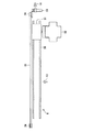
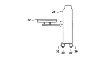
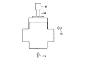
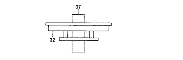
図4は、図1乃至図3に示すドアシェル搬送機8の具体的構成を示す上面図である。図5は、図4に示す矢印13の方向から視たドアシェル搬送機の構成を示す側面図である。図6は、図4に示す矢印14の方向から視たドアシェル搬送機の構成を示す側面図である。図7は、図4乃至6に示すオープナー及びその回転機構を示す上面図である。図8は、図7に示す矢印15の方向から視たオープナー及びその回転機構を示す側面図である。図9は、図7に示す矢印16の方向から視たオープナー及びその回転機構を示す側面図である。
FIG. 4 is a top view showing a specific configuration of the door shell conveyor 8 shown in FIGS. 1 to 3. FIG. 5 is a side view showing the configuration of the door shell conveyor as viewed from the direction of the
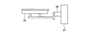
図4乃至6に示すように、ドアシェル搬送機8はオープナー32を備えており、このオープナー32は、ドアシェルを吸着して保持し、FOUPの状態にあるドアシェルとポッドシェルを分離する分離機能と、ポッドシェルとドアシェルを結合させてFOUPを組み立てる組み立て機能とを有している。前記分離機能は、ドアシェルとポッドシェルを結合しているロック部(留め具)を外す機能である。前記組み立て機能は、ドアシェルとポッドシェルをロック部(留め具)によって結合する機能である。
As shown in FIGS. 4 to 6, the door shell transfer machine 8 includes an
図7乃至9に示すように、オープナー32は回転軸38を介してロータリーアクチュエーター37に接続されている。ロータリーアクチュエーター37によって回転軸38を回転させることにより、オープナー32を180°回転させることができるようになっている。つまり、オープナー32は、上に向いている状態(図4〜図9に示すように重力方向と略逆方向を向いている状態)と下に向いている状態(略重力方向を向いている状態)が得られるようになっている。オープナー32が上に向いている状態ではオープナー32の上にドアシェルを保持することができ、オープナー32が下に向いている状態ではオープナー32の下にドアシェルを保持することができる。
As shown in FIGS. 7 to 9, the
ロータリーアクチュエーター37は、図4乃至6に示す搬送機筐体31に収容されている。この搬送機筐体31内にはロータリーアクチュエーター37を昇降させる昇降機構(図示せず)が配置されている。この昇降機構によってロータリーアクチュエーター37とともにオープナー32を昇降させることができるようになっている。
搬送機筐体31の下部にはガイド36が設けられており、このガイド36はガイドレール39上を自在に移動できるように構成されている。
The
A
搬送機筐体31はタイミングベルト35に連結されており、タイミングベルト35は一対のタイミングプーリー34に巻かれている。一方のタイミングプーリー34はギアを介してACサーボモーター33に接続されている。ACサーボモーター33の回転駆動力はギアを経由してタイミングプーリー34に伝達され、タイミングプーリー34が回転することによりタイミングベルト35が動かされるように構成されている。つまり、ACサーボモーター33の回転数を図示せぬ制御部で制御することにより、タイミングベルト35の動く量を制御することができ、その結果、搬送機筐体31の位置を制御することができる。
The
次に、上記ドアシェル搬送機8の動作について図4乃至図9を参照しつつ説明する。
洗浄しようとするFOUPをドアシェルを下に向けた状態で、図4乃至図9に示す状態のオープナー32の上に置いて吸着保持させ、このFOUPをオープナー32によりロック部を外してドアシェルとポッドシェルに分離する。
Next, the operation of the door shell conveyor 8 will be described with reference to FIGS.
The FOUP to be cleaned is placed on the
次いで、分離したポッドシェルは図1に示すドアシェル槽−ポッドシェル槽間搬送機9によってポッドシェル洗浄槽4に搬送する。次いで、オープナー32をロータリーアクチュエーター37によって回転軸38とともに180°回転させる。これにより、オープナー32によってドアシェルが下向きに保持され、このドアシェルの内面は下に向いた状態となる。
Next, the separated pod shell is transferred to the pod shell cleaning tank 4 by the door shell tank-pod shell
次に、搬送機筐体31内の昇降機構によってロータリーアクチュエーター37とともにオープナー32を下降させ、内面が下に向いた状態のドアシェルをドアシェル洗浄リンス槽に設置する。次いで、ドアシェル洗浄リンス槽1において前述したような方法で薬液洗浄を行い、純水でリンスする。
Next, the
次いで、洗浄リンス後のドアシェルをオープナー32によって吸着して保持し、このオープナー32を昇降機構によって上昇させ、オープナー32を180°回転させることによりドアシェルを上向に保持する。このようにしてドアシェルをドアシェル洗浄リンス槽1の上方に移動させる。次いで、ACサーボモーター33の駆動力を、ギア、タイミングプーリー34及びタイミングベルト35を介して搬送機筐体31に伝達することにより、オープナー32とともにドアシェルをドアシェル水切り槽2の上方に移動させる。この際、ドアシェルを上向に保持した状態で該ドアシェルを移動させるため、純水や薬液が垂れることを抑制できる。次いで、搬送機筐体31内の昇降機構によってロータリーアクチュエーター37とともにオープナー32を下降させ、内面が下に向いた状態のドアシェルをドアシェル水切り槽2に設置する。次いで、ドアシェル水切り槽2において前述したような方法でドアシェルの水切りを行う。
Next, the door shell after the cleaning rinse is adsorbed and held by the
次に、水切り後のドアシェルをオープナー32によって吸着して保持し、このオープナー32を昇降機構によって上昇させ、ドアシェルをドアシェル水切り槽2の上方に移動させる。次いで、ACサーボモーター33の駆動力を、ギア、タイミングプーリー34及びタイミングベルト35を介して搬送機筐体31に伝達することにより、オープナー32とともにドアシェルをドアシェル乾燥槽3の上方に移動させる。次いで、搬送機筐体31内の昇降機構によってロータリーアクチュエーター37とともにオープナー32を下降させ、内面が下に向いた状態のドアシェルをドアシェル乾燥槽3に設置する。次いで、ドアシェル乾燥槽3において前述したような方法でドアシェルの乾燥を行う。
Next, the drained door shell is adsorbed and held by the
次いで、乾燥後のドアシェルをオープナー32によって吸着して保持し、このオープナー32を昇降機構によって上昇させ、オープナー32を180°回転させ、ドアシェルをドアシェル乾燥槽3の上方に移動させる。また、乾燥後のポッドシェルをドアシェル槽−ポッドシェル槽間搬送機9によってポッドシェル乾燥槽6からドアシェル乾燥槽3の上方のオープナー32上に搬送する。次いで、オープナー32の組み立て機能によりドアシェルとポッドシェルを留め具によって結合してFOUPを組み立てる。そして、FOUPをFOUP洗浄乾燥装置から取り出す。
Next, the dried door shell is adsorbed and held by the
上記ドアシェル搬送機によれば、オープナー32をロータリーアクチュエーター37によって回転軸38とともに180°回転させる構成としているため、ドアシェル搬送機を小型化することができる。これにより、FOUP洗浄乾燥装置のレイアウトを効率化することができ、装置を小型化することができる。
According to the door shell transporter, the
尚、本発明は上記実施の形態に限定されず、本発明の主旨を逸脱しない範囲内で種々変更して実施することが可能である。例えば、上記実施の形態では、オープナーをドアシェル搬送機に取り付けているが、オープナーをドアシェル槽−ポッドシェル槽間搬送機に取り付けることも可能である。この場合、ドアシェル槽−ポッドシェル槽間搬送機のオープナーにFOUPを置き、このオープナーによってドアシェルとポッドシェルを分離した後、ポッドシェル搬送機7によってポッドシェルの開口部を下に向けて該ポッドシェルをポッドシェル洗浄槽4内に設置し、ドアシェル槽−ポッドシェル槽間搬送機によってドアシェルの内面を下に向けて該ドアシェルをドアシェル洗浄リンス槽1に搬送する。また、乾燥後のドアシェルをドアシェル槽−ポッドシェル槽間搬送機のオープナーによってドアシェル乾燥槽3からポッドシェル乾燥槽6の上方又は近傍に搬送し、乾燥後のポッドシェルをポッドシェル搬送機7によって前記オープナー上に搬送し、前記オープナーによってドアシェルとポッドシェルを結合してFOUPを組み立てる。
Note that the present invention is not limited to the above-described embodiment, and various modifications can be made without departing from the spirit of the present invention. For example, in the above embodiment, the opener is attached to the door shell carrier, but the opener may be attached to the door shell tank-pod shell tank carrier. In this case, the FOUP is placed on the opener of the door shell tank-pod shell tank transfer machine, the door shell and the pod shell are separated by this opener, and then the pod shell opening machine pod shell is directed downward by the pod
1…ドアシェル洗浄リンス槽
2…ドアシェル水切り槽
3…ドアシェル乾燥槽
4…ポッドシェル洗浄槽
5…ポッドシェル水切り槽
6…ポッドシェル乾燥槽
7…ポッドシェル搬送機
8…ドアシェル搬送機
9…ドアシェル槽−ポッドシェル槽間搬送機
10…薬液供給ユニット
11,110…電源ボックス
12,111…クリーンユニット
13〜16,21,22,101〜103…矢印
31…搬送機筐体
32…オープナー
33…ACサーボモーター
34…タイミングプーリー
35…タイミングベルト
36…ガイド
37…ロータリーアクチュエーター
38…回転軸
39…ガイドレール
80…FOUP
81…開口部
82…ポッドシェル
83…ドアシェル
84…パッキン
85…内面
86…ロック部
104…ドアシェル洗浄槽
105…ドアシェル乾燥槽
106…ポッドシェル洗浄槽
107…ポッドシェル乾燥槽
108…ポッドシェル搬送機
109…ドアシェル搬送機
DESCRIPTION OF SYMBOLS 1 ... Door shell washing | cleaning rinse
DESCRIPTION OF
Claims (8)
FOUPにおいてポッドシェルからドアシェルを分離する分離機能を有するとともに前記ドアシェルを保持する保持機能を有する分離保持機構と、
前記分離保持機構を回転させる回転機構と、
を具備することを特徴とするドアシェル搬送機。 In the door shell transporter that transports the door shell,
A separation holding mechanism having a separation function of separating the door shell from the pod shell in the FOUP and a holding function of holding the door shell;
A rotating mechanism for rotating the separation holding mechanism;
A door shell transporter comprising:
前記分離したドアシェルを略180°回転させることにより、前記ドアシェルの内面を略重力方向に向かせ、
前記ドアシェルの内面を略重力方向に向かせた状態で該ドアシェルを処理槽に設置することを特徴とするドアシェル搬送方法。 The door shell is separated from the pod shell in the FOUP in a state where the inner surface of the door shell is directed in a direction substantially opposite to the direction of gravity,
By rotating the separated door shell by approximately 180 °, the inner surface of the door shell is directed in the direction of gravity,
A door shell conveying method, wherein the door shell is installed in a processing tank in a state where the inner surface of the door shell is directed in a substantially gravitational direction.
前記ドアシェルを略180°回転させることにより、前記ドアシェルの内面を重力方向と略逆方向に向かせ、
前記略逆方向を向いた状態の前記ドアシェルにポッドシェルを結合させてFOUPを組み立てることを特徴とするドアシェル搬送方法。 Raising the door shell installed in the treatment tank in a state where the inner surface of the door shell is directed substantially in the direction of gravity, from the treatment tank;
By rotating the door shell approximately 180 °, the inner surface of the door shell is directed in a direction substantially opposite to the direction of gravity,
A door shell transfer method comprising assembling a FOUP by assembling a pod shell to the door shell in the substantially opposite direction.
8. The door shell transfer method according to claim 6, wherein the treatment tank is any one of a door shell cleaning rinse tank, a door shell draining tank, and a door shell drying tank.
Priority Applications (1)
| Application Number | Priority Date | Filing Date | Title |
|---|---|---|---|
| JP2005317453A JP2007123771A (en) | 2005-10-31 | 2005-10-31 | Door shell carrier and door shell carrying method |
Applications Claiming Priority (1)
| Application Number | Priority Date | Filing Date | Title |
|---|---|---|---|
| JP2005317453A JP2007123771A (en) | 2005-10-31 | 2005-10-31 | Door shell carrier and door shell carrying method |
Publications (1)
| Publication Number | Publication Date |
|---|---|
| JP2007123771A true JP2007123771A (en) | 2007-05-17 |
Family
ID=38147247
Family Applications (1)
| Application Number | Title | Priority Date | Filing Date |
|---|---|---|---|
| JP2005317453A Withdrawn JP2007123771A (en) | 2005-10-31 | 2005-10-31 | Door shell carrier and door shell carrying method |
Country Status (1)
| Country | Link |
|---|---|
| JP (1) | JP2007123771A (en) |
Cited By (1)
| Publication number | Priority date | Publication date | Assignee | Title |
|---|---|---|---|---|
| KR101898477B1 (en) | 2017-05-16 | 2018-10-05 | 주식회사 아이에스티이 | Cover holder for cleaning carrier cover |
-
2005
- 2005-10-31 JP JP2005317453A patent/JP2007123771A/en not_active Withdrawn
Cited By (1)
| Publication number | Priority date | Publication date | Assignee | Title |
|---|---|---|---|---|
| KR101898477B1 (en) | 2017-05-16 | 2018-10-05 | 주식회사 아이에스티이 | Cover holder for cleaning carrier cover |
Similar Documents
| Publication | Publication Date | Title |
|---|---|---|
| US6395101B1 (en) | Single semiconductor wafer processor | |
| CN110364431B (en) | Substrate processing method and substrate processing device | |
| JP4401285B2 (en) | Substrate processing equipment | |
| US20080142051A1 (en) | Recovery cup cleaning method and substrate treatment apparatus | |
| JP7149087B2 (en) | Substrate processing method and substrate processing apparatus | |
| CN106876300B (en) | Substrate processing apparatus and substrate processing method | |
| JP7066471B2 (en) | Board processing method and board processing equipment | |
| JP2002110609A (en) | Cleaning equipment | |
| JP7402984B2 (en) | Substrate processing module and substrate processing equipment | |
| JP2002126678A (en) | Method and apparatus for cleaning tightly closed type container | |
| US6668844B2 (en) | Systems and methods for processing workpieces | |
| JP2003031538A (en) | Substrate processing apparatus and substrate processing method | |
| JP2007123771A (en) | Door shell carrier and door shell carrying method | |
| JP6100486B2 (en) | Immersion cleaning device | |
| JPH10303170A (en) | Device and method for cleaning substrate | |
| JP2000049215A (en) | Processing system | |
| JP2007123769A (en) | Apparatus and method of foup cleaning and drying | |
| JP3066986B2 (en) | Wet processing apparatus and wet processing method | |
| JP2002136935A (en) | Cleaning treatment apparatus and cleaning treatment method | |
| JPH1131676A (en) | Cleaning system | |
| KR20230098469A (en) | Apparatus for treating substrate and method for processing a substrate | |
| JP2003031537A (en) | Substrate processing equipment | |
| JP2000114224A (en) | Substrate cleaning device | |
| US20080029123A1 (en) | Sonic and chemical wafer processor | |
| JP2007129160A (en) | Pod-shell cleaning apparatus and pod-shell cleaning method |
Legal Events
| Date | Code | Title | Description |
|---|---|---|---|
| A300 | Withdrawal of application because of no request for examination |
Free format text: JAPANESE INTERMEDIATE CODE: A300 Effective date: 20090106 |