JP2007119216A - Suction device for cell of solar cell - Google Patents
Suction device for cell of solar cell Download PDFInfo
- Publication number
- JP2007119216A JP2007119216A JP2005316394A JP2005316394A JP2007119216A JP 2007119216 A JP2007119216 A JP 2007119216A JP 2005316394 A JP2005316394 A JP 2005316394A JP 2005316394 A JP2005316394 A JP 2005316394A JP 2007119216 A JP2007119216 A JP 2007119216A
- Authority
- JP
- Japan
- Prior art keywords
- suction
- pad
- solar cell
- adsorption
- vacuum box
- Prior art date
- Legal status (The legal status is an assumption and is not a legal conclusion. Google has not performed a legal analysis and makes no representation as to the accuracy of the status listed.)
- Pending
Links
Images


Classifications
-
- Y—GENERAL TAGGING OF NEW TECHNOLOGICAL DEVELOPMENTS; GENERAL TAGGING OF CROSS-SECTIONAL TECHNOLOGIES SPANNING OVER SEVERAL SECTIONS OF THE IPC; TECHNICAL SUBJECTS COVERED BY FORMER USPC CROSS-REFERENCE ART COLLECTIONS [XRACs] AND DIGESTS
- Y02—TECHNOLOGIES OR APPLICATIONS FOR MITIGATION OR ADAPTATION AGAINST CLIMATE CHANGE
- Y02E—REDUCTION OF GREENHOUSE GAS [GHG] EMISSIONS, RELATED TO ENERGY GENERATION, TRANSMISSION OR DISTRIBUTION
- Y02E10/00—Energy generation through renewable energy sources
- Y02E10/50—Photovoltaic [PV] energy
Abstract
Description
本発明は、太陽電池セルを1枚ずつ吸着する吸着装置に関するものである。 The present invention relates to an adsorption device that adsorbs solar cells one by one.
一般に、太陽電池モジュールは、複数枚の太陽電池セルを接続してストリングを形成し、複数行のストリングを接続して面状に製造される。この場合、複数枚の太陽電池セルを接続してストリングを形成する際、隣接する太陽電池セルのパスバー(集電部)間は、断面偏平な方形状の導体、例えば、銅または銅合金から形成されたリードを介して接続されている。具体的には、図7に示すように、一の太陽電池セルPの表面側パスバーに半田を介してリードLの一半部を溶着する一方、一の太陽電池セルPに溶着されたリードLの他半部を隣接する太陽電池セルPの裏面側パスバーに半田を介して溶着することにより、複数枚の太陽電池セルPを順次接続してストリングを製造するようにしている(例えば、特許文献1参照)。 Generally, a solar cell module is manufactured in a planar shape by connecting a plurality of solar cells to form a string, and connecting a plurality of rows of strings. In this case, when a plurality of solar cells are connected to form a string, a conductor having a flat cross-section, for example, copper or a copper alloy is formed between the pass bars (current collectors) of adjacent solar cells. Connected through leads. Specifically, as shown in FIG. 7, one half of the lead L is welded to the surface-side path bar of one solar cell P via solder, while the lead L welded to one solar cell P The other half is welded to the back-side path bar of the adjacent solar battery cell P via solder, whereby a plurality of solar battery cells P are sequentially connected to manufacture a string (for example, Patent Document 1). reference).
このように、太陽電池セルのパスバーにリードを溶着するため、多数枚の積層された状態で保管されている太陽電池セルを1枚ずつ吸着する吸着装置を設けるとともに、太陽電池セルを位置決めしてリードの溶着作業位置に搬送する搬送ベルトを備えた搬送装置を設け、吸着装置を介して吸着された太陽電池セルを搬送ベルトの設定位置に移載した後、太陽電池セルを搬送ベルトに吸着して溶着作業位置に搬送するようにしている(例えば、特許文献2参照)。
ところで、前述した吸着装置は、真空ボックスの下面にスポンジなどの通気性保持部材を設けて構成され、真空ボックスを緩やかな減圧状態に維持し、太陽電池セルを通気性保持部材を介して吸着し、搬送ベルトの設定位置まで移送するようにしている。この場合、太陽電池セルは、厚みが0.3〜0.5mmと薄く、多数枚の積層状態で保管されて、隣接する太陽電池セル間に空気が入り込まないように密着していることにより、真空ボックスを減圧して太陽電池セルを吸着すると、複数枚の太陽電池セルが同時に吸着されるという問題があった。このため、後工程である太陽電池セルに対するリードの溶着作業を行なうことができず、作業効率が低下するものとなっていた。 By the way, the adsorption device described above is configured by providing a breathable holding member such as a sponge on the lower surface of the vacuum box, maintaining the vacuum box in a moderately reduced pressure state, and adsorbing the solar cells via the breathable holding member. , And transport to the set position of the conveyor belt. In this case, the solar cell has a thin thickness of 0.3 to 0.5 mm, is stored in a stacked state of a large number of sheets, and is in close contact so that air does not enter between adjacent solar cells, When the vacuum box is decompressed and the solar cells are adsorbed, there is a problem that a plurality of solar cells are adsorbed simultaneously. For this reason, the welding operation of the lead | read | reed with respect to the photovoltaic cell which is a post process cannot be performed, but the work efficiency fell.
なお、鋼板などの板状体を吸着して搬送する際、複数枚の板状体の同時吸着を防止するため、中央に固定部を設けるとともに、その左右に吸着パッドを設け、板状体の中間部を固定部によって持ち上がらないように支持するとともに、その左右端部を吸着パッドによって吸着することにより、下方の板状体から切り離すことが行なわれているが、このような方法を太陽電池セルに適用することはできない。 In addition, when adsorbing and transporting a plate-like body such as a steel plate, in order to prevent simultaneous adsorption of a plurality of plate-like bodies, a fixing portion is provided at the center and suction pads are provided on the left and right sides of the plate-like body. The intermediate part is supported by the fixed part so as not to be lifted, and the left and right end parts thereof are adsorbed by the suction pads, so that they are separated from the lower plate-like body. It cannot be applied to.
すなわち、太陽電池セルは脆弱な性状であり、吸着する際、固定部が下降して太陽電池セルに衝突すると、太陽電池セルは固定部との衝撃によって割れなどを引き起こす。また、太陽電池セルと固定部との間に隙間を確保したとしても、太陽電池セルは、吸着パッドによって持ち上げられると、固定部と衝突して衝撃を受けるとともに、同時に、その左右端部が吸着パッドによって持ち上げられて固定部に支持される中間部に対して曲げを受けることとなり、簡単に割れなどの破損に発展するものである。 That is, the solar cell has a fragile property. When the solar cell is adsorbed, when the fixed portion descends and collides with the solar cell, the solar cell causes a crack or the like due to an impact with the fixed portion. Even if a gap is secured between the solar cell and the fixed part, when the solar cell is lifted by the suction pad, the solar cell collides with the fixed part and receives an impact. The intermediate part lifted by the pad and supported by the fixed part is subjected to bending, and easily develops to breakage such as cracks.
このような傾向は、厚みが0.15〜0.2mmとさらに薄くなる昨今の太陽電池セルにおいては、特に顕著となる。 Such a tendency becomes particularly prominent in recent solar cells in which the thickness is further reduced to 0.15 to 0.2 mm.
本発明は、このような問題点に鑑みてなされたもので、複数枚の積層状態で保管されている太陽電池セルを破損させることなく1枚ずつ確実に取り出すことのできる吸着装置を提供するものである。 The present invention has been made in view of such problems, and provides an adsorption device that can reliably take out solar cells stored in a stacked state one by one without damaging them. It is.
本発明は、中空の真空ボックスと、吸着パッドを有して真空ボックスの左右方向中央部に接続された第1吸着部材と、下端面が第1吸着部材の吸着パッドの下端面と同一水平面上に位置する吸着パッドを有して真空ボックスの左右端部に接続された第2吸着部材と、から構成され、真空ボックスを減圧して第1吸着部材の吸着パッドおよび第2吸着部材の吸着パッドによって太陽電池セルを吸着した際の第2吸着部材の吸着パッドの縮み代が第1吸着部材の吸着パッドの縮み代よりも大きいことを特徴とするものである。 The present invention includes a hollow vacuum box, a first suction member having a suction pad and connected to a central portion in the left-right direction of the vacuum box, and a lower end surface on the same horizontal plane as a lower end surface of the suction pad of the first suction member And a second suction member connected to the left and right ends of the vacuum box and having a suction pad located on the vacuum box, the suction pad of the first suction member and the suction pad of the second suction member by depressurizing the vacuum box Thus, the contraction margin of the suction pad of the second adsorption member when the solar cells are adsorbed is larger than the contraction margin of the adsorption pad of the first adsorption member.
本発明によれば、真空ボックスを下降させ、それらの吸着パッドを最上層の太陽電池セルに接地させた後、真空ボックスを減圧し、第1吸着部材の吸着パッドおよび第2吸着部材の吸着パッドによって太陽電池セルを吸着する。この際、吸着パッドに作用する真空圧によって太陽電池セルを吸着すると、吸着パッドは縮み、その縮み分だけ太陽電池セルを上方に持ち上げる。ここで、第2吸着部材の吸着パッドの縮み代が第1吸着部材の吸着パッドの縮み代よりも大きいことから、太陽電池セルの左右がその中央部よりも高い位置に持ち上げられる。太陽電池セルが持ち上げられると、その裏面と次層の太陽電池セルの表面との間に空気が入り込み、次層の太陽電池セルから切り離すことができる。 According to the present invention, the vacuum box is lowered and the suction pads are grounded to the uppermost solar cell, and then the vacuum box is depressurized, and the suction pad of the first suction member and the suction pad of the second suction member To adsorb the solar cells. At this time, if the solar cell is adsorbed by the vacuum pressure acting on the adsorption pad, the adsorption pad contracts, and the solar cell is lifted upward by the amount of the contraction. Here, since the contraction margin of the suction pad of the second suction member is larger than the contraction margin of the suction pad of the first suction member, the left and right sides of the solar battery cell are lifted to a position higher than the central portion. When the solar cell is lifted, air enters between the back surface and the surface of the solar cell in the next layer, and can be separated from the solar cell in the next layer.
一方、吸着パッドによって太陽電池セルを吸着するとき、左右を吸着する吸着パッドとともに中央部を吸着する吸着パッドも一定長さだけ縮むことから、太陽電池セルの中央部に作用する衝撃を緩衝することができるとともに、太陽電池セルに作用する曲げは、第1吸着部材の吸着パッドが縮む分だけ小さくなる。 On the other hand, when the solar cell is adsorbed by the adsorbing pad, the adsorbing pad that adsorbs the central portion together with the adsorbing pad that adsorbs the left and right sides contracts by a certain length, so that the shock acting on the central portion of the solar cell is buffered. In addition, the bending acting on the solar battery cell is reduced by the amount of contraction of the suction pad of the first suction member.
この結果、太陽電池セルを1枚ずつ確実に吸着することができる。しかも、吸着時の衝撃を緩衝することができるとともに、曲げを相対的に小さくすることができることから、吸着に伴う太陽電池セルの破損を確実に防止することができる。 As a result, the solar cells can be reliably adsorbed one by one. In addition, the impact at the time of adsorption can be buffered and the bending can be made relatively small, so that damage to the solar battery cell due to adsorption can be reliably prevented.
本発明において、前記第1吸着部材の吸着パッドがフラットパッドであり、第2吸着部材の吸着パッドがベローズパッドであることが好ましい。 In the present invention, it is preferable that the suction pad of the first suction member is a flat pad, and the suction pad of the second suction member is a bellows pad.
本発明において、前記真空ボックスが上方より見てT字状または工字状であることが好ましい。特に、真空ボックスがT字状であると、太陽電池セルの前後左右が持ち上げられて曲げられる工字状の場合に比較して、持ち上げられて曲げられる個所が半減し、より薄い太陽電池セルを吸着する場合に好ましい。 In the present invention, it is preferable that the vacuum box has a T shape or a work shape as viewed from above. In particular, when the vacuum box is T-shaped, compared to the case of a craft shape where the front, rear, left and right sides of the solar battery cell are lifted and bent, the number of parts that can be lifted and bent is halved, and a thinner solar battery cell is obtained. It is preferable when adsorbing.
本発明において、前記第2吸着部材の吸着パッドによって吸着された太陽電池セルに向かって横方向から圧縮空気が供給されると、吸着された太陽電池セルの裏面と次層の太陽電池セルの裏面との間に圧縮空気を供給して、吸着された太陽電池セルを次層の太陽電池セルから強制的に切り離すことができるため、好ましい。 In the present invention, when compressed air is supplied from the lateral direction toward the solar cell adsorbed by the adsorption pad of the second adsorption member, the back surface of the adsorbed solar cell and the back surface of the next-layer solar cell The compressed solar cell can be forcibly separated from the solar cell of the next layer by supplying compressed air between and.
本発明によれば、複数枚の積層状態で保管されている太陽電池セルを破損させることなく1枚ずつ確実に取り出すことができる。 ADVANTAGE OF THE INVENTION According to this invention, it can take out one by one reliably, without damaging the photovoltaic cell stored by the lamination | stacking state of several sheets.
以下、本発明の実施の形態を図面に基づいて詳細に説明する。 Hereinafter, embodiments of the present invention will be described in detail with reference to the drawings.
図1乃至図3には、本発明の太陽電池セルPの吸着装置1の一実施形態が記載されている。
1 to 3 show an embodiment of the
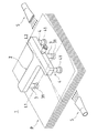
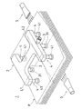
この吸着装置1は、図示しないブロアーなどの空気源に接続され、上方より見てT字状に形成された中空の真空ボックス2と、真空ボックス2の左右方向の中央部に位置して前後方向に間隔をおいて接続された2個の第1吸着部材3と、真空ボックス2の左右端部に位置して接続された2個の第2吸着部材4と、から構成され、詳細には図示しないが、昇降装置を介して吸着位置と上方に退避した位置との間を昇降可能であるとともに、移送装置を介して退避位置と図示しない搬送ベルトの設定位置を臨む位置との間を移送可能となっている。そして、第1吸着部材3には、吸着パッドとしてフラットパッド31が設けられ、第2吸着部材4には、吸着パッドとしてベローズパッド41が設けられており、それらのフラットパッド31の下端面およびベローズパッド41の下端面は、同一水平面上に位置するようにそれぞれ真空ボックス2に配管接続されている。
This
これらのフラットパッド31およびベローズパッド41は、市販品であって、よく知られているように、シリコンゴムやウレタンなどの弾性材から形成されている。
The
ここで、真空ボックス2の前後方向の縦寸法は、太陽電池セルPの縦寸法よりも短小に設定され、その左右方向の横寸法は、太陽電池セルPの横寸法よりも短小に設定されている。また、真空ボックス2は、多数枚の積層状態で保管された太陽電池セルPの中心を通る縦方向のラインL1上に第1吸着部材3の中心が位置するように、かつ、太陽電池セルPの中心を通る横方向のラインL2が前後の第1吸着部材3をほぼ均等に分かつように、太陽電池セルPに対向して配設されている。
Here, the vertical dimension in the front-rear direction of the
なお、積層された太陽電池セルPの左右外方には、図示しないブロアーなどの空気源に接続された圧縮空気の噴出ノズル5が第2吸着パッド4と対向するように配置されており、噴出ノズル5を通して圧縮空気を太陽電池セルPに向けて噴出することができる。
In addition, a compressed
次に、このように構成された吸着装置1の作動について説明する。
Next, the operation of the
初期状態では、真空ボックス2は、太陽電池セルPの上方に退避する位置にある。この状態から、図示しない昇降装置を作動させると、吸着装置1を下降させ、第1吸着部材3のフラットパッド31の下端面および第2吸着部材4のベローズパッド41の下端面を最上層の太陽電池セルPの表面に接地させる(図2および図3参照)。この際、第1吸着部材3のフラットパッド31および第2吸着部材4のベローズパッド41が緩やかに太陽電池セルPに接地するように、接地直前の下降速度を減速させることが好ましい。
In the initial state, the
次いで、空気源を作動させ、真空ボックス2の内部空気を吸引すると、真空ボックス2および該真空ボックス2に接続された第1吸着部材3および第2吸着部材4は負圧状態に維持される。これにより、各第1吸着部材3のフラットパッド31および各第2吸着部材4のベローズパッド41は、最上層の太陽電池セルPを吸着する。この際、図4および図5に示すように、第2吸着部材4のベローズパッド41の縮み代δ2は、第1吸着部材3のフラットパッド31の縮み代δ1に比較して相対的に大きく、第2吸着部材4のベローズパッド41に吸着される太陽電池セルPの前半部の左右は、第1吸着部材3のフラットパッド31に吸着される太陽電池セルPの中央部よりも上方に持ち上げられる。しかも、第1吸着部材3のフラットパッド31もその縮み代δ1に相当する高さだけ太陽電池セルPを上方に持ち上げており、第2吸着部材4のベローズパッド41による太陽電池セルPの吸着による持ち上げに伴うフラットパッド31への衝突を材質と合わせて緩衝するとともに、全体として、第2吸着部材4のベローズパッド41の縮み代δ2と第1吸着部材3のフラットパッド31の縮み代δ1との差に相当する曲げが発生するにすぎず、中間部が上方に移動することなく支持する場合に比較して,第1吸着部材3のフラットパッド31の縮み代δ1に相当する分だけ曲げが小さくなる。
Next, when the air source is operated and the internal air of the
第2吸着部材4のベローズパッド41に吸着される太陽電池セルPの前半部の左右が、第1吸着部材3のフラットパッド31に吸着される太陽電池セルPの左右方向中間部よりも相対的に上方に持ち上げられると、持ち上げられた最上層の太陽電池セルPと次層の太陽電池セルPとの間に空気が入り込むことから、最上層の太陽電池セルPを次層の太陽電池セルPから切り離すことができる。
The left and right of the front half of the solar cell P adsorbed by the
この際、噴出ノズル5から圧縮空気を噴出させれば、持ち上げられた最上層の太陽電池セルPの裏面と次層の太陽電池セルPの表面との間に圧縮空気を横方向から強制的に供給することができ、次層の太陽電池セルPから最上層の太陽電池セルPの切り離しを助長することができる。
At this time, if compressed air is ejected from the
このようにして、最上層の太陽電池セルPが次層の太陽電池セルPから切り離されたならば、昇降装置を作動させて上方に退避させるとともに、移送装置を作動させ、搬送ベルトの設定位置の上方まで移送させた後、再び昇降装置を作動させて吸着装置1を下降させ、太陽電池セルPを搬送ベルトの設定位置に載置する。次いで、空気源の作動を停止し、真空ボックス2の内部空気を大気に開放すれば、その負圧状態が解除されることから、太陽電池セルPは、自重により設定位置上に切り離される。太陽電池セルPが切り離されたならば、昇降装置を介して吸着装置1を上昇させるとともに、移送装置を介して太陽電池セルPの上方に退位した位置に移送される。
In this way, when the uppermost solar cell P is separated from the next solar cell P, the lifting device is operated and retracted upward, the transfer device is operated, and the conveying belt is set at the position. Then, the lifting / lowering device is operated again to lower the
この際、保管された太陽電池セルPは、図示しない昇降装置を介して1枚分の厚みに相当する高さだけ持ち上げられており、次層の太陽電池セルPは、その上面が先の最上層の太陽電池セルPの上面と同じ高さ位置にある。 At this time, the stored solar cell P is lifted by a height corresponding to the thickness of one sheet via a lifting device (not shown), and the upper surface of the next-layer solar cell P is the topmost. It exists in the same height position as the upper surface of the upper photovoltaic cell P.
以下、新たな最上層の太陽電池セルPについても、同様に吸着装置1を作動させて吸着するものである。
Hereinafter, the new uppermost solar cell P is similarly adsorbed by operating the
ところで、前述した実施形態においては、真空ボックス2を上方よりT字状に形成し、その中央部の前後に第1吸着部材3を設けるとともに、左右に第2吸着部材4を設けた場合を説明したが、図6に示すように、真空ボックス2を上方より見て工字状に形成し、その中央部の前後に第1吸着部材3を設けるとともに、各第1吸着部材3を挟むように、それぞれ左右に第2吸着部材4を設けるようにしてもよい。
By the way, in embodiment mentioned above, the
この場合は、4個の第2吸着部材4が対向する太陽電池セルPの前半部の左右および後半部の左右が曲げられるため、太陽電池セルPの前半部の左右のみが曲げられる前述した実施形態の場合に比較して、全体として大きな曲げが作用することになる。したがって、許容される太陽電池セルPの曲げを考慮して選択する必要がある。
In this case, since the left and right of the front half of the solar cell P facing the four
また、前述した実施形態においては、第1吸着部材3にフラットパッド31を設ける一方、第2吸着部材4にフラットパット31の縮み代δ1よりも大きな縮み代δ2を有するベローズパッド41を設けた場合を例示したが、例えば、中央部に設けられる第1吸着部材3の吸着パッドとしてベローズパッドを採用し、左右に設けられる第2吸着部材4の吸着パッドとして多段ベローズパッドを作用してもよい。いずれにしても、中央部に設けられる第1吸着部材3の吸着パッドの縮み代δ1よりも、左右に設けられる第2吸着部材4の吸着パッドの縮み代δ2が相対的に大きければよい。
Further, in the above-described embodiment, when the
1 吸着装置
2 真空ボックス
3 第1吸着部材
31 フラットパッド(吸着パッド)
4 第2吸着部材
41 ベローズパッド(吸着パッド)
5 噴出ノズル
P 太陽電池セル
1
4
5 Jet nozzle P Solar battery cell
Claims (4)
Priority Applications (1)
| Application Number | Priority Date | Filing Date | Title |
|---|---|---|---|
| JP2005316394A JP2007119216A (en) | 2005-10-31 | 2005-10-31 | Suction device for cell of solar cell |
Applications Claiming Priority (1)
| Application Number | Priority Date | Filing Date | Title |
|---|---|---|---|
| JP2005316394A JP2007119216A (en) | 2005-10-31 | 2005-10-31 | Suction device for cell of solar cell |
Publications (1)
| Publication Number | Publication Date |
|---|---|
| JP2007119216A true JP2007119216A (en) | 2007-05-17 |
Family
ID=38143468
Family Applications (1)
| Application Number | Title | Priority Date | Filing Date |
|---|---|---|---|
| JP2005316394A Pending JP2007119216A (en) | 2005-10-31 | 2005-10-31 | Suction device for cell of solar cell |
Country Status (1)
| Country | Link |
|---|---|
| JP (1) | JP2007119216A (en) |
Cited By (8)
| Publication number | Priority date | Publication date | Assignee | Title |
|---|---|---|---|---|
| JP2010052836A (en) * | 2008-08-26 | 2010-03-11 | Kyocera Corp | Resin sheet conveyance device, and method for conveying resin sheet using the same |
| JP2010070376A (en) * | 2008-09-22 | 2010-04-02 | K D K Kk | Paper feeding method and paper feeding device |
| JP2011246211A (en) * | 2010-05-24 | 2011-12-08 | Toyama Kikai Kk | Device and method for transferring solar cell |
| JP2016011178A (en) * | 2014-06-27 | 2016-01-21 | 三星ダイヤモンド工業株式会社 | Method and device for conveying brittle material substrate |
| JP2018065642A (en) * | 2016-10-18 | 2018-04-26 | Nke株式会社 | Tray separator |
| KR20180103259A (en) * | 2017-03-09 | 2018-09-19 | 주식회사 엘지화학 | Static Eliminator with Purge and Transfer Device |
| WO2020153307A1 (en) * | 2019-01-21 | 2020-07-30 | 株式会社東京精密 | Wafer peeling and cleaning apparatus |
| WO2023234706A1 (en) * | 2022-06-03 | 2023-12-07 | 주식회사 엘지에너지솔루션 | Device and method for manufacturing electrode assembly |
-
2005
- 2005-10-31 JP JP2005316394A patent/JP2007119216A/en active Pending
Cited By (10)
| Publication number | Priority date | Publication date | Assignee | Title |
|---|---|---|---|---|
| JP2010052836A (en) * | 2008-08-26 | 2010-03-11 | Kyocera Corp | Resin sheet conveyance device, and method for conveying resin sheet using the same |
| JP2010070376A (en) * | 2008-09-22 | 2010-04-02 | K D K Kk | Paper feeding method and paper feeding device |
| JP2011246211A (en) * | 2010-05-24 | 2011-12-08 | Toyama Kikai Kk | Device and method for transferring solar cell |
| JP2016011178A (en) * | 2014-06-27 | 2016-01-21 | 三星ダイヤモンド工業株式会社 | Method and device for conveying brittle material substrate |
| JP2018065642A (en) * | 2016-10-18 | 2018-04-26 | Nke株式会社 | Tray separator |
| KR20180103259A (en) * | 2017-03-09 | 2018-09-19 | 주식회사 엘지화학 | Static Eliminator with Purge and Transfer Device |
| KR102265233B1 (en) * | 2017-03-09 | 2021-06-16 | (주)엘지에너지솔루션 | Static Eliminator with Purge and Transfer Device |
| WO2020153307A1 (en) * | 2019-01-21 | 2020-07-30 | 株式会社東京精密 | Wafer peeling and cleaning apparatus |
| CN113302720A (en) * | 2019-01-21 | 2021-08-24 | 株式会社东京精密 | Wafer stripping and cleaning device |
| WO2023234706A1 (en) * | 2022-06-03 | 2023-12-07 | 주식회사 엘지에너지솔루션 | Device and method for manufacturing electrode assembly |
Similar Documents
| Publication | Publication Date | Title |
|---|---|---|
| JP2007119216A (en) | Suction device for cell of solar cell | |
| KR101734271B1 (en) | Automatic stack system for fuel cell | |
| JP5708892B2 (en) | Sheet material adhesive application method | |
| JP5296741B2 (en) | Solar cell transfer device and transfer method thereof | |
| JP2013214739A (en) | Method of peeling semiconductor chip from metal foil | |
| JP2012056648A (en) | Sheet stacking device | |
| JP7020168B2 (en) | Fuel cell separator carrier | |
| JP2017152075A (en) | Supply device for electrode plate of secondary battery, and control method therefor | |
| JP2015012246A (en) | Substrate supply device, and method thereof | |
| JP5432204B2 (en) | Electrode foil conveying device and laminated battery manufacturing device | |
| JP7384781B2 (en) | Sheet separation device | |
| JP3911405B2 (en) | Sheet take-out apparatus and sheet take-out method | |
| JP2017084498A (en) | Transport device for electrode foil, and manufacturing device for lamination type battery | |
| JP2019099330A (en) | Manufacturing method for glass plate and transport device for glass plate | |
| JP2008297033A (en) | Device and method for transferring glass sheet | |
| JP2010120774A (en) | Vessel group lift-down device and vessel group lift-down method | |
| JP2018104181A (en) | Thin plate takeout device and thin plate takeout method | |
| JP2009160713A (en) | Conveyance device and conveying method | |
| KR101167076B1 (en) | Plate transporting appratus | |
| JP2006021856A (en) | Sheet conveying device, sheet conveying method, and solar cell module manufacturing method using the method | |
| JP5247303B2 (en) | Resin sheet conveying apparatus and resin sheet conveying method using the apparatus | |
| JP2013095558A (en) | Sheet taking-out method, and sheet taking-out device | |
| JPH06179534A (en) | Separating method of sheet material | |
| US20240124250A1 (en) | Suction gripping device and method for receiving and storing flat flexible substrates | |
| CN219246650U (en) | Jacking device convenient for silicon wafer transfer |
Legal Events
| Date | Code | Title | Description |
|---|---|---|---|
| A977 | Report on retrieval |
Free format text: JAPANESE INTERMEDIATE CODE: A971007 Effective date: 20070927 |
|
| A131 | Notification of reasons for refusal |
Free format text: JAPANESE INTERMEDIATE CODE: A131 Effective date: 20071002 |
|
| A02 | Decision of refusal |
Free format text: JAPANESE INTERMEDIATE CODE: A02 Effective date: 20080219 |