JP2007108466A - Image forming method, image forming apparatus and toner set - Google Patents
Image forming method, image forming apparatus and toner set Download PDFInfo
- Publication number
- JP2007108466A JP2007108466A JP2005299822A JP2005299822A JP2007108466A JP 2007108466 A JP2007108466 A JP 2007108466A JP 2005299822 A JP2005299822 A JP 2005299822A JP 2005299822 A JP2005299822 A JP 2005299822A JP 2007108466 A JP2007108466 A JP 2007108466A
- Authority
- JP
- Japan
- Prior art keywords
- toner
- cyan toner
- image forming
- lightness
- cyan
- Prior art date
- Legal status (The legal status is an assumption and is not a legal conclusion. Google has not performed a legal analysis and makes no representation as to the accuracy of the status listed.)
- Pending
Links
Images


Abstract
Description
本発明は、電子写真や静電印刷の如き画像形成方法、画像形成装置及びそれらに用いられるシアントナーセットおよびマゼンタトナーセットに関する。 The present invention relates to an image forming method such as electrophotography and electrostatic printing, an image forming apparatus, and a cyan toner set and a magenta toner set used in the image forming apparatus.
電子写真式カラー画像形成装置が広く普及するに従い、その用途も多種多様に広がり、その画像品質への要求も厳しくなってきている。一般の写真、カタログ、地図の如き画像の複写では、微細な部分に至るまで、極めて微細に且つ忠実に再現することが求められており、それに伴い、色の鮮やかさに対する要求も高まっており、色再現範囲を拡張することが望まれている。特に、印刷分野への進出が著しい昨今、電子写真方式においても印刷の品質と同等以上の高精細性が要求されるようになっている。 As electrophotographic color image forming apparatuses become widespread, their applications have been diversified and demands on image quality have become stricter. When copying images such as general photographs, catalogs, and maps, it is required to reproduce very finely and faithfully, even down to the finest parts. It is desired to extend the color reproduction range. In recent years, especially in the field of printing, where high-definition is required, the electrophotographic method is required to have high definition equal to or higher than the printing quality.
最近のデジタルな画像信号を使用している電子写真方式の画像形成装置では、潜像は一定電位のドットが潜像担持体、所謂感光体の表面に集まって形成されており、ベタ部、ハーフトーン部及びライン部はドット密度をかえることによって表現されている。しかしながらこの方法では、ドットに忠実にトナー粒子が現像されず、ドットからトナー粒子がはみ出した状態となり、デジタル潜像の黒部と白部のドット密度の比に対応するトナー画像の階調性が得られないという問題が起こり易い。更に、画質を向上させるために、ドットサイズを小さくして解像度を向上させる場合には、微小なドットから形成される潜像の再現性が更に困難になり、解像度及び特にハイライト部の階調性の悪い、シャープネスさに欠けた画像となる傾向がある。また、不規則なドットの乱れは粒状感として感じられ、ハイライト部の画質を低下させる要因となる。このような画像は、銀塩写真画質に肉薄してきた昨今のインクジェット技術と比べた場合、劣っていると言わざるを得ない。 In a recent electrophotographic image forming apparatus using a digital image signal, a latent image is formed by gathering dots of a constant potential on the surface of a latent image carrier, a so-called photoconductor. The tone part and the line part are expressed by changing the dot density. However, with this method, the toner particles are not developed faithfully to the dots, and the toner particles protrude from the dots, and the gradation of the toner image corresponding to the ratio of the black density and the white density of the digital latent image is obtained. The problem of not being able to occur is likely to occur. Furthermore, when the resolution is improved by reducing the dot size in order to improve the image quality, the reproducibility of the latent image formed from minute dots becomes more difficult, and the resolution and particularly the gradation of the highlight area There is a tendency for images to be poor and lack sharpness. Further, irregular dot irregularities are perceived as graininess, which causes a reduction in the image quality of the highlight portion. Such an image has to be said to be inferior when compared with the recent ink jet technology which has been thinned to the silver salt photographic image quality.
これらを改善する目的で、ベタ部は濃い色のトナー(濃トナー)、ハイライト部はそれより濃度の薄いトナー(淡トナー)を用いて画像を形成する方法が提案されている。 In order to improve these, a method has been proposed in which an image is formed using a dark color toner (dark toner) in the solid portion and a lighter toner (light toner) in the highlight portion.
例えば、それぞれ濃度の異なる複数のトナーを組み合わせて画像形成する画像形成方法が提案されている(例えば、特許文献1及び2参照)。また、濃色トナーの最大反射濃度に対し、その半分以下の最大反射濃度を有する淡色トナーを組み合わせた画像形成装置が提案されている(例えば、特許文献3参照)。また、記録部材上でのトナー量が5g/m2のときの画像濃度が1.0以上である濃色トナーと、1.0未満である淡色トナーとを組み合わせた画像形成装置が提案されている(例えば、特許文献4参照)。これらの技術によってハイライト部の画質は向上されるが、淡色トナーのみで色諧調を出すためには、高濃度部ではトナーを多量に記録部材上に載せなければならない。また、フルカラー画像においてはシアン、マゼンタ、イエロー及びブラックトナーのほかに更に淡色トナーを重ねると記録部材上に載るトナー量は膨大なものとなる。
For example, an image forming method for forming an image by combining a plurality of toners each having a different density has been proposed (see, for example,
一方で、封筒、ハガキ及びラベル紙等、比較的薄い紙(40g/m2紙)から比較的厚い紙(200g/m2紙)まで、幅の広狭や長さの長短によらず、多種多様な第2の画像担持体を選択できるようにするための手段として、中間転写体を有する画像形成装置がある。中間転写体を有する画像形成装置では、感光体等の第1の画像担持体と中間転写体との1次転写部、及び第2の画像担持体へ画像の転写を行う2次転写部と、2回の転写を行うため、トナー自身の高い転写性が要求される。トナーの粒度分布や外添剤の種類によって転写性を向上させることが試みられているが(例えば、特許文献5参照)、濃トナーと淡トナーを組み合わせた画像形成装置のように、膨大なトナー量を使用するシステムにおいては更なる改善が望まれている。 On the other hand, a wide variety of papers such as envelopes, postcards and label papers, from relatively thin paper (40 g / m 2 paper) to relatively thick paper (200 g / m 2 paper), regardless of width or length. As a means for enabling selection of a second image carrier, there is an image forming apparatus having an intermediate transfer member. In an image forming apparatus having an intermediate transfer member, a primary transfer unit between a first image carrier such as a photosensitive member and an intermediate transfer member, and a secondary transfer unit that transfers an image to the second image carrier; Since the transfer is performed twice, high transferability of the toner itself is required. Attempts have been made to improve transferability depending on the particle size distribution of the toner and the type of external additive (see, for example, Patent Document 5). However, an enormous amount of toner is used as in an image forming apparatus combining dark toner and light toner. Further improvements are desired in systems that use quantities.
本発明は、上記の従来技術の問題点を解決し得る画像形成方法、画像形成装置及びカラートナーセットを提供することを課題とする。 It is an object of the present invention to provide an image forming method, an image forming apparatus, and a color toner set that can solve the above-described problems of the prior art.
即ち、本発明は、低濃度領域から高濃度領域まで、粒状感、がさつきを低減できるトナーセット、画像形成方法及び画像形成装置を提供することを目的とする。 That is, an object of the present invention is to provide a toner set, an image forming method, and an image forming apparatus that can reduce graininess and roughness from a low density region to a high density region.
また本発明は、中間転写体を有する画像形成装置を用いて記録部材上に多量のトナーを載せても1次転写、2次転写ともに優れた転写性を示し、環境の変動においても色味の変動を起こしにくいトナーセット及び画像形成方法を提供することを目的とする。 In addition, the present invention shows excellent transferability in both primary transfer and secondary transfer even when a large amount of toner is placed on a recording member using an image forming apparatus having an intermediate transfer member, and can be tinted even in environmental changes. An object of the present invention is to provide a toner set and an image forming method that hardly cause fluctuations.
本発明の目的は、以下により達成される。 The object of the present invention is achieved by the following.
すなわち、
(1)中間転写体を有する画像形成装置と、フルカラー画像形成に用いられるシアントナーaとシアントナーbとを用いる画像形成方法において、
該シアントナーaは、少なくとも結着樹脂、着色剤、及びワックスを含有し、粉体状態における明度L*(a)が45〜75であり、
該シアントナーbは、少なくとも結着樹脂、着色剤、及びワックスを含有し、粉体状態における明度L*(b)が、シアントナーaの明度L*(a)より低く、
該シアントナーaとシアントナーbの荷重9.8×10⁻⁵Nに対する最大変位量をそれぞれSa、Sbとし、塑性変位量をそれぞれIa、Ibとしたとき、下式
Ea=(Sa−Ia)×100/Sa
Eb=(Sb−Ib)×100/Sb
で表される弾性変形率Ea、Ebが
0%≦|Ea−Eb|≦10%
を満たすことを特徴とする画像形成方法に関する。
That is,
(1) In an image forming apparatus having an intermediate transfer member and an image forming method using cyan toner a and cyan toner b used for full color image formation,
The cyan toner a contains at least a binder resin, a colorant, and a wax, and has a lightness L * (a) of 45 to 75 in a powder state.
The cyan toner b contains at least a binder resin, a colorant, and wax, and the lightness L * (b) in the powder state is lower than the lightness L * (a) of the cyan toner a.
When the maximum displacement amounts of the cyan toner a and cyan toner b with respect to the load of 9.8 × 10 −5 N are Sa and Sb, respectively, and the plastic displacement amounts are Ia and Ib, respectively, Ea = (Sa−Ia) × 100 / Sa
Eb = (Sb−Ib) × 100 / Sb
The elastic deformation ratios Ea and Eb represented by 0% ≦ | Ea−Eb | ≦ 10%
The present invention relates to an image forming method.
(2)該シアントナーaと該シアントナーbを荷重9.8×10⁻⁵Nで変形させたものを、更に9.8×10⁻⁵Nの荷重を加えたときの弾性変形率(Ea2)、(Eb2)がそれぞれ55%以上であることを特徴とする画像形成方法に関する。 (2) said cyan those deformed by the load 9.8 × 10 -5 N toner a and the cyan toner b, further 9.8 × 10 -5 N elastic deformation ratio when a load is applied in (Ea2 ) And (Eb2) are each 55% or more.
(3)中間転写体を有する画像形成装置と、フルカラー画像形成に用いられるシアントナーaとシアントナーbとを用いる画像形成装置において、
該シアントナーaは、少なくとも結着樹脂、着色剤、及びワックスを含有し、粉体状態における明度L*(a)が45〜75であり、
該シアントナーbは、少なくとも結着樹脂、着色剤、及びワックスを含有し、粉体状態における明度L*(b)が、シアントナーaの明度L*(a)より低く、
該シアントナーaとシアントナーbの荷重9.8×10⁻⁵Nに対する最大変位量をそれぞれSa、Sbとし、塑性変位量をそれぞれIa、Ibとしたとき、下式
Ea=(Sa−Ia)×100/Sa
Eb=(Sb−Ib)×100/Sb
で表される弾性変形率Ea、Ebが
0%≦|Ea−Eb|≦10%
を満たすことを特徴とする画像形成装置に関する。
(3) In an image forming apparatus having an intermediate transfer member and an image forming apparatus using cyan toner a and cyan toner b used for full color image formation,
The cyan toner a contains at least a binder resin, a colorant, and a wax, and has a lightness L * (a) of 45 to 75 in a powder state.
The cyan toner b contains at least a binder resin, a colorant, and wax, and the lightness L * (b) in the powder state is lower than the lightness L * (a) of the cyan toner a.
When the maximum displacement amounts of the cyan toner a and cyan toner b with respect to the load of 9.8 × 10 −5 N are Sa and Sb, respectively, and the plastic displacement amounts are Ia and Ib, respectively, Ea = (Sa−Ia) × 100 / Sa
Eb = (Sb−Ib) × 100 / Sb
The elastic deformation ratios Ea and Eb represented by 0% ≦ | Ea−Eb | ≦ 10%
The present invention relates to an image forming apparatus.
(4)フルカラー画像形成に用いられ、シアントナーaとシアントナーbとを含有するシアントナーセットにおいて、
該シアントナーaは、少なくとも結着樹脂、着色剤、及びワックスを含有し、粉体状態における明度L*(a)が45〜75であり、
該シアントナーbは、少なくとも結着樹脂、着色剤、及びワックスを含有し、粉体状態における明度L*(b)が、シアントナーaの明度L*(a)より低く、
該シアントナーaとシアントナーbの荷重9.8×10⁻⁵Nに対する最大変位量をそれぞれSa、Sbとし、塑性変位量をそれぞれIa、Ibとしたとき、下式
Ea=(Sa−Ia)×100/Sa
Eb=(Sb−Ib)×100/Sb
で表される弾性変形率Ea、Ebが
0%≦|Ea−Eb|≦10%
を満たすことを特徴とするシアントナーセットに関する。
(4) In a cyan toner set used for full color image formation and containing cyan toner a and cyan toner b,
The cyan toner a contains at least a binder resin, a colorant, and a wax, and has a lightness L * (a) of 45 to 75 in a powder state.
The cyan toner b contains at least a binder resin, a colorant, and wax, and the lightness L * (b) in the powder state is lower than the lightness L * (a) of the cyan toner a.
When the maximum displacement amounts of the cyan toner a and cyan toner b with respect to the load of 9.8 × 10 −5 N are Sa and Sb, respectively, and the plastic displacement amounts are Ia and Ib, respectively, Ea = (Sa−Ia) × 100 / Sa
Eb = (Sb−Ib) × 100 / Sb
The elastic deformation ratios Ea and Eb represented by 0% ≦ | Ea−Eb | ≦ 10%
The present invention relates to a cyan toner set characterized by satisfying
(5)該シアントナーaおよび該シアントナーbを荷重9.8×10⁻⁵Nで変形させたものを、更に9.8×10⁻⁵Nの荷重を加えたときの弾性変形率(Ea2)、(Eb2)がそれぞれ55%以上であることを特徴とするシアントナーセットに関する。 (5) said those deformed by the load 9.8 × 10 -5 N cyan toner a and the cyan toner b, the elastic deformation rate when further applying a load of 9.8 × 10 -5 N (Ea2 ) And (Eb2) are each 55% or more.
(6)該シアントナーaおよび該シアントナーbの円相当径2μm以上の粒子において、平均円形度が0.920〜0.970であることを特徴とするシアントナーセットに関する。 (6) The cyan toner set is characterized in that the average circularity of the cyan toner a and the cyan toner b having a circle-equivalent diameter of 2 μm or more is 0.920 to 0.970.
(7)中間転写体を有する画像形成装置と、フルカラー画像形成に用いられるマゼンタトナーaとマゼンタトナーbとを用いる画像形成方法において、
該マゼンタトナーaは、少なくとも結着樹脂、着色剤、及びワックスを含有し、粉体状態における明度L*(a)が45〜75であり、
該マゼンタトナーbは、少なくとも結着樹脂、着色剤、及びワックスを含有し、粉体状態における明度L*(b)が、マゼンタトナーaの明度L*(a)より低く、
該マゼンタトナーaとマゼンタトナーbの荷重9.8×10⁻⁵Nに対する最大変位量をそれぞれ(Sa)、(Sb)および塑性変位量をそれぞれ(Ia)、(Ib)としたとき、の弾性変形率(Ea)、(Eb)が下記式
Ea=(Sa−Ia)×100/Sa
Eb=(Sb−Ib)×100/Sb
0%≦|Ea−Eb|≦10%
を満たすことを特徴とする画像形成方法に関する。
(7) In an image forming method using an image forming apparatus having an intermediate transfer member and magenta toner a and magenta toner b used for full color image formation,
The magenta toner a contains at least a binder resin, a colorant, and a wax, and has a lightness L * (a) of 45 to 75 in a powder state.
The magenta toner b contains at least a binder resin, a colorant, and a wax, and the lightness L * (b) in the powder state is lower than the lightness L * (a) of the magenta toner a.
Elasticity when the maximum displacement amounts of the magenta toner a and the magenta toner b with respect to the load of 9.8 × 10 −5 N are (Sa) and (Sb) and the plastic displacement amounts are (Ia) and (Ib), respectively. Deformation rates (Ea) and (Eb) are expressed by the following formula: Ea = (Sa−Ia) × 100 / Sa
Eb = (Sb−Ib) × 100 / Sb
0% ≦ | Ea−Eb | ≦ 10%
The present invention relates to an image forming method.
(8)該マゼンタトナーaと該マゼンタトナーbを荷重9.8×10⁻⁵Nで変形させたものを、更に9.8×10⁻⁵Nの荷重を加えたときの弾性変形率(Ea2)、(Eb2)がそれぞれ55%以上であることを特徴とする画像形成方法に関する。 (8) The magenta those toner a and the magenta toner b is deformed with a load 9.8 × 10 -5 N, further 9.8 × 10 -5 N elastic deformation ratio when a load is applied in (Ea2 ) And (Eb2) are each 55% or more.
(9)中間転写体を有する画像形成装置と、フルカラー画像形成に用いられるマゼンタトナーaとマゼンタトナーbとを用いる画像形成装置において、
該マゼンタトナーaは、少なくとも結着樹脂、着色剤、及びワックスを含有し、粉体状態における明度L*(a)が45〜75であり、
該マゼンタトナーbは、少なくとも結着樹脂、着色剤、及びワックスを含有し、粉体状態における明度L*(b)が、マゼンタトナーaの明度L*(a)より低く、
該マゼンタトナーaとマゼンタトナーbの荷重9.8×10⁻⁵Nに対する最大変位量をそれぞれ(Sa)、(Sb)および塑性変位量をそれぞれ(Ia)、(Ib)としたとき、の弾性変形率(Ea)、(Eb)が下記式
Ea=(Sa−Ia)×100/Sa
Eb=(Sb−Ib)×100/Sb
0%≦|Ea−Eb|≦10%
を満たすことを特徴とする画像形成装置に関する。
(9) In an image forming apparatus having an intermediate transfer member and an image forming apparatus using magenta toner a and magenta toner b used for full-color image formation,
The magenta toner a contains at least a binder resin, a colorant, and a wax, and has a lightness L * (a) of 45 to 75 in a powder state.
The magenta toner b contains at least a binder resin, a colorant, and a wax, and the lightness L * (b) in the powder state is lower than the lightness L * (a) of the magenta toner a.
Elasticity when the maximum displacement amounts of the magenta toner a and the magenta toner b with respect to the load of 9.8 × 10 −5 N are (Sa) and (Sb) and the plastic displacement amounts are (Ia) and (Ib), respectively. Deformation rates (Ea) and (Eb) are expressed by the following formula: Ea = (Sa−Ia) × 100 / Sa
Eb = (Sb−Ib) × 100 / Sb
0% ≦ | Ea−Eb | ≦ 10%
The present invention relates to an image forming apparatus.
(10)フルカラー画像形成に用いられ、マゼンタトナーaとマゼンタトナーbとを含有するマゼンタトナーセットにおいて、
該マゼンタトナーaは、少なくとも結着樹脂、着色剤、及びワックスを含有し、粉体状態における明度L*(a)が45〜75であり、
該マゼンタトナーbは、少なくとも結着樹脂、着色剤、及びワックスを含有し、粉体状態における明度L*(b)が、マゼンタトナーaの明度L*(a)より低く、
該マゼンタトナーaとマゼンタトナーbの荷重9.8×10⁻⁵Nに対する最大変位量をそれぞれ(Sa)、(Sb)および塑性変位量をそれぞれ(Ia)、(Ib)としたとき、の弾性変形率(Ea)、(Eb)が下記式
Ea=(Sa−Ia)×100/Sa
Eb=(Sb−Ib)×100/Sb
0%≦|Ea−Eb|≦10%
を満たすことを特徴とするマゼンタトナーセットに関する。
(10) In a magenta toner set used for full color image formation and containing magenta toner a and magenta toner b.
The magenta toner a contains at least a binder resin, a colorant, and a wax, and has a lightness L * (a) of 45 to 75 in a powder state.
The magenta toner b contains at least a binder resin, a colorant, and a wax, and the lightness L * (b) in the powder state is lower than the lightness L * (a) of the magenta toner a.
Elasticity when the maximum displacement amounts of the magenta toner a and the magenta toner b with respect to the load of 9.8 × 10 −5 N are (Sa) and (Sb) and the plastic displacement amounts are (Ia) and (Ib), respectively. Deformation rates (Ea) and (Eb) are expressed by the following formula: Ea = (Sa−Ia) × 100 / Sa
Eb = (Sb−Ib) × 100 / Sb
0% ≦ | Ea−Eb | ≦ 10%
The present invention relates to a magenta toner set characterized by satisfying
(11)該マゼンタトナーaおよび該マゼンタトナーbを荷重9.8×10⁻⁵Nで変形させたものを、更に9.8×10⁻⁵Nの荷重を加えたときの弾性変形率(Ea2)、(Eb2)がそれぞれ55%以上であることを特徴とするマゼンタトナーセットに関する。 (11) those obtained by modifying the magenta toner a and the magenta toner b at a load 9.8 × 10 -5 N, further 9.8 × 10 -5 N elastic deformation ratio when a load is applied in (Ea2 ) And (Eb2) are 55% or more, respectively.
(12)該マゼンタトナーaおよび該マゼンタトナーbの円相当径2μm以上の粒子において、平均円形度が0.920〜0.970であることを特徴とするマゼンタトナーセットに関する。 (12) The present invention relates to a magenta toner set characterized in that the average circularity is 0.920 to 0.970 in particles having an equivalent circle diameter of 2 μm or more of the magenta toner a and the magenta toner b.
本発明では、中間転写体を有し、且つ濃色トナーと淡色トナーを組み合わせたシステムを有する画像形成装置において、環境変動を伴っても、感光体等の第1の画像担持体と中間転写体間の転写性(1次転写性)及び中間転写体と記録部材等の第2の画像担持体との転写性(2次転写性)ともに転写性が高く、色味変動の発生を抑えることができる。 In the present invention, in an image forming apparatus having an intermediate transfer member and having a system combining dark toner and light toner, the first image carrier such as a photosensitive member and the intermediate transfer member, even with environmental fluctuations. Transferability between the intermediate transfer member (primary transfer property) and transfer property between the intermediate transfer member and the second image carrier such as a recording member (secondary transfer property) is high, and the occurrence of color variation can be suppressed. it can.
本発明において明度L*は粉体状態のトナーとして求めた値を示している。一般に明度L*は、L*a*b*系表色系において、色相及び彩度に関係なく比較できる色の明るさの度合いを0〜100の範囲で示すものである。本発明において、粉体状態のトナーにおけるL*は、分光式色差計「SE−2000」(日本電色工業社製)を用いて測定したものである。 In the present invention, the lightness L * indicates a value obtained as a toner in a powder state. In general, the lightness L * indicates the degree of brightness of colors that can be compared regardless of hue and saturation in the L * a * b * system color system. In the present invention, L * in the toner in the powder state is measured using a spectroscopic color difference meter “SE-2000” (manufactured by Nippon Denshoku Industries Co., Ltd.).
本発明においてL*が45以上のトナー(以下、これを「トナーa」と表記することがある)とは、通常のトナーに比べ、着色力を抑え、明度を高くしたものである。明度の高いトナーを用いるとハイライト部の画像が良好である理由は以下の通りである。ハイライト部の画像を明度の低い(色の濃い)トナーで形成すると、トナーが現像された明度の低い部分は局部的に高い濃度となり、トナーの現像されない部分とくっきりしたコントラストが出来る。この場合ハイライト部では、当然トナーの現像されない部分が多く、そこに明度の低い高濃度の点がばらまかれた形状の画像が形成される。これは結果的には、極めて粒状感の目立つ画像となる。 In the present invention, a toner having an L * of 45 or more (hereinafter sometimes referred to as “toner a”) is a toner having reduced coloring power and increased brightness as compared with a normal toner. The reason why the image in the highlight portion is good when toner having high brightness is used is as follows. When an image in a highlight portion is formed with toner with low brightness (deep color), a low brightness portion where the toner is developed has a locally high density, and a clear contrast is formed with a portion where the toner is not developed. In this case, in the highlight portion, there are naturally many portions where the toner is not developed, and an image having a shape in which high-density points with low brightness are dispersed is formed. This results in an image with a noticeable graininess.
そこで本発明では、ハイライト部を粒子当たりの明度が高いトナーを用いて紙とトナーとの明度の差を少なくし、その替わりに通常より多量のトナーで現像することにすれば、同一濃度が前記の現像より多数のトナー即ち画像点(色点)により形成されるので、結果的には前記画像より粒状性の点で良好な(粒状感の少ない)ハイライト部が形成されることになる。 Therefore, in the present invention, if the highlight portion is made of toner having high brightness per particle to reduce the difference in brightness between paper and toner, and instead developed with a larger amount of toner than usual, the same density can be obtained. Since it is formed by a larger number of toners, that is, image points (color points) than the above development, as a result, a highlight portion having better graininess (less graininess) than the image is formed. .
本発明において、トナーの明度を定着した後の画像の分光感度特性ではなく、粉体状態における分光感度特性で規定したのは以下の理由による。定着器や記録部材には様々な種類が存在し、その条件及び組み合わせによって、同一のトナーを定着した場合にでも発現するグロスや色域は大きく変化する。また、定着器の圧力によって、トナーの潰れ方も異なり、それは粒状性(がさつき)に影響を及ぼす。その点、本発明による直接的な測色方法を採用すると、定着器の構成や転写物に影響されないため、トナーそのものの明度を的確に規定することができる。 In the present invention, the lightness of the toner is defined not by the spectral sensitivity characteristic of the image after fixing, but by the spectral sensitivity characteristic in the powder state for the following reason. There are various types of fixing devices and recording members. Depending on the conditions and combinations thereof, the gloss and color gamut that appear even when the same toner is fixed vary greatly. Also, depending on the pressure of the fixing device, the way the toner is crushed differs, which affects the graininess (roughness). In that respect, when the direct colorimetry method according to the present invention is employed, the brightness of the toner itself can be accurately defined because it is not affected by the structure of the fixing device or the transferred material.
形成される画像のベタ部に濃色トナー(以下、これを「トナーb」と表記することがある)を用い、ハイライト部は上記本発明の淡色トナー(トナーa)を用いるといった具合に、画像の濃度によってトナーを使い分け、画像を形成するとより好ましい効果が得られる。また、形成される画像の濃度階調に応じて、濃色トナー(トナーb)と淡色トナー(トナーa)とを適宜組み合わせて用いることも好ましい形態である。これは、マゼンタ(M)、シアン(C)いずれの色のトナーに用いても同様な効果が得られる。 For example, a dark toner (hereinafter sometimes referred to as “toner b”) is used for the solid portion of the image to be formed, and the light color toner (toner a) of the present invention is used for the highlight portion. A more preferable effect can be obtained by using different toners depending on the image density to form an image. It is also preferable to use a combination of dark toner (toner b) and light toner (toner a) as appropriate in accordance with the density gradation of the image to be formed. The same effect can be obtained regardless of whether the toner is magenta (M) or cyan (C).
確かにこの方法では、粒状感、がさつきを抑えた画像を出力することができた。しかし、ハガキ及びラベル紙等、比較的薄い紙(40g/m2紙)から比較的厚い紙(200g/m2紙)といった多種多様な画像担持体を選択できるようにするため、中間転写体を有する画像形成装置を用いた場合、新たな問題として特に環境変動において転写不良が原因の色味変動が発生し易いことが分かった。 Certainly, this method was able to output an image with reduced graininess and roughness. However, in order to be able to select a wide variety of image carriers from relatively thin paper (40 g / m 2 paper) to relatively thick paper (200 g / m 2 paper), such as postcards and label paper, an intermediate transfer member is used. In the case of using the image forming apparatus having the above, it has been found that, as a new problem, color variation due to transfer failure is likely to occur particularly in environmental variation.
本発明者らは、例えば高温高湿環境(30℃/湿度80%)及び常温低湿環境(23℃/湿度5%)の各環境で濃色、淡色のシアントナーセット、およびマゼンタトナーセットを用いて、それぞれシアン、マゼンタの色階調を出力し原因を確認したところ、濃色トナーと淡色トナーで環境によって最適な転写条件が異なることが分かった。そして本発明者らは濃色、淡色トナーで転写条件を最適化できる物性値に関する検討を試みた。そして鋭意検討の結果、転写性と相関があるトナーの弾性変形率を濃色トナーと淡色トナーで出来るだけ同等にすることで濃色トナーと淡色トナーの最適な転写条件を近づけることができるという新たな知見を得た。 The inventors of the present invention use, for example, dark and light cyan toner sets and magenta toner sets in a high temperature and high humidity environment (30 ° C./humidity 80%) and a normal temperature and low humidity environment (23 ° C./humidity 5%). When the cause was confirmed by outputting cyan and magenta color gradations, it was found that optimum transfer conditions differ depending on the environment for dark toner and light toner. Then, the present inventors tried to study physical property values that can optimize transfer conditions with dark and light toners. As a result of diligent research, the optimum transfer conditions for dark toner and light toner can be brought closer by making the elastic deformation rate of toner correlated with transferability as much as possible between dark toner and light toner. I got a good knowledge.
本発明において、中間転写体を有する画像形成装置と、フルカラー画像形成に用いられるシアントナーa(淡色シアントナー)とシアントナーb(濃色シアントナー)とを用いる画像形成方法において、シアントナーaとシアントナーbの荷重9.8×10⁻⁵Nに対する最大変位量をそれぞれSa、Sbとし、塑性変位量をそれぞれIa、Ibとしたとき、下式
Ea=(Sa−Ia)×100/Sa
Eb=(Sb−Ib)×100/Sb
で表される弾性変形率Ea、Ebが
0%≦|Ea−Eb|≦10%
を満たすことが、環境特性に関わらず濃色、淡色シアントナーの最適な転写条件を近づけ、色味変動を防止するために重要である。
In the present invention, in an image forming apparatus having an intermediate transfer member and an image forming method using cyan toner a (light cyan toner) and cyan toner b (dark cyan toner) used for full color image formation, cyan toner a and When the maximum displacement amounts of cyan toner b with respect to a load of 9.8 × 10 −5 N are Sa and Sb, respectively, and the plastic displacement amounts are Ia and Ib, respectively, Ea = (Sa−Ia) × 100 / Sa
Eb = (Sb−Ib) × 100 / Sb
The elastic deformation ratios Ea and Eb represented by 0% ≦ | Ea−Eb | ≦ 10%
Satisfying these conditions is important in order to bring close to the optimum transfer conditions for dark and light cyan toners, regardless of environmental characteristics, and to prevent color variations.
また、同様に中間転写体を有する画像形成装置と、フルカラー画像形成に用いられるマゼンタトナーa(淡色マゼンタトナー)とマゼンタトナーb(濃色マゼンタトナー)とを用いる画像形成方法において、マゼンタトナーaとマゼンタトナーbの荷重9.8×10⁻⁵Nに対する最大変位量をそれぞれSa、Sbとし、塑性変位量をそれぞれIa、Ibとしたとき、下式
Ea=(Sa−Ia)×100/Sa
Eb=(Sb−Ib)×100/Sb
で表される弾性変形率Ea、Ebが
0%≦|Ea−Eb|≦10%
を満たすことが、環境特性に関わらず濃色、淡色マゼンタトナーの最適な転写条件を近づけ、色味変動を防止するために重要である。
Similarly, in an image forming apparatus having an intermediate transfer member and an image forming method using magenta toner a (light magenta toner) and magenta toner b (dark magenta toner) used for full color image formation, magenta toner a When the maximum displacement amounts of the magenta toner b with respect to the load of 9.8 × 10 −5 N are Sa and Sb, respectively, and the plastic displacement amounts are Ia and Ib, respectively, Ea = (Sa−Ia) × 100 / Sa
Eb = (Sb−Ib) × 100 / Sb
The elastic deformation ratios Ea and Eb represented by 0% ≦ | Ea−Eb | ≦ 10%
Satisfying these conditions is important in order to bring close to the optimum transfer conditions for dark and light magenta toners regardless of environmental characteristics and to prevent variations in color.
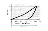
ここで、トナーの最大変位量(Sa、Sb)とは、特定の荷重に対してトナーが最大でどれだけ変形するのかを示す量であり、塑性変位量(Ia、Ib)とは特定の荷重を加えられて変形したトナーが、除荷された後に元に戻らずに変形した量を示す値である。そして最大変位量と塑性変位量から算出される弾性変形率(Ea、Eb)である。図12に荷重9.8×10⁻⁵N(10mgf)におけるトナーの変位量の測定結果を示す。 Here, the maximum amount of toner displacement (Sa, Sb) is an amount indicating how much the toner is deformed at maximum with respect to a specific load, and the amount of plastic displacement (Ia, Ib) is a specific load. This is a value indicating the amount of toner deformed without being restored after being unloaded. The elastic deformation rates (Ea, Eb) calculated from the maximum displacement amount and the plastic displacement amount. FIG. 12 shows the measurement results of the amount of toner displacement at a load of 9.8 × 10 −5 N (10 mgf).
本発明ではトナーaとトナーbの弾性変形率(Ea、Eb)をできるだけ近づけることが重要である。 In the present invention, it is important to make the elastic deformation rates (Ea, Eb) of the toner a and the toner b as close as possible.
トナーの最大変位量はトナー中の結着樹脂の分子量や架橋密度に影響される。具体的には分子量分が大きく硬いトナーであると、トナーの最大変位量は小さくなる。トナーの結着樹脂の組成や製造方法によってトナーの最大変位量は調整可能であるが、製造方法で調整する具体的な手段としては、重合トナーでは反応時間、温度、開始剤の選択等がある。また粉砕トナーでは架橋剤を添加することによって分子量を大きくする方法、混練温度等の調整で混練シェアを大きくし、結着樹脂の分子鎖を切断するといった方法がある。 The maximum displacement amount of the toner is affected by the molecular weight and the crosslinking density of the binder resin in the toner. Specifically, when the toner has a large molecular weight and is hard, the maximum displacement amount of the toner becomes small. The maximum amount of displacement of the toner can be adjusted by the composition of the binder resin of the toner and the manufacturing method. Specific means for adjusting the manufacturing method include selection of reaction time, temperature, initiator, etc. for the polymerized toner. . For pulverized toner, there are a method of increasing the molecular weight by adding a crosslinking agent, and a method of increasing the kneading share by adjusting the kneading temperature and cutting the molecular chains of the binder resin.
また、塑性変位量はトナー中の添加剤で調整できる。例えば、離型剤を添加する場合は塑性変位量は大きくなる。またフィラーとして働くような添加剤を選んで添加することにより、塑性変位量は小さくなる。 Further, the amount of plastic displacement can be adjusted with an additive in the toner. For example, when a release agent is added, the amount of plastic displacement increases. Further, by selecting and adding an additive that works as a filler, the amount of plastic displacement is reduced.
従来のトナーaとトナーbにおいては、着色剤の量を変えただけであったため、特に塑性変位量の値がトナーaとトナーbとで異なる。本発明者らの検討結果では、トナーaの方が塑性変位量が小さくなり、弾性変形率も差を生じる傾向にあった。また、トナーaとトナーbで着色剤の種類を同じにすることがトナー生産性やコストの面から好ましいが、この場合、トナーaとトナーbで色味が若干異なる傾向にある。このため、|Ea−Eb|が10%を超えると、環境変動において転写不良が原因の色味変動が発生し易くなる。 In the conventional toner a and toner b, since only the amount of the colorant is changed, the value of the plastic displacement amount is particularly different between the toner a and the toner b. According to the examination results of the present inventors, the toner a tends to have a smaller amount of plastic displacement and a difference in elastic deformation rate. Further, it is preferable from the viewpoint of toner productivity and cost that the same colorant is used for toner a and toner b, but in this case, the colors of toner a and toner b tend to be slightly different. For this reason, if | Ea−Eb | exceeds 10%, color variations due to transfer defects are likely to occur in environmental variations.
本発明においては、|Ea−Eb|を10%以下にする方法として、理想的には塑性変位量と最大変位量をトナーa、トナーbで近づけることで|Ea−Eb|を10%以下にすることであるが、トナーaとトナーbの塑性変位量と最大変位量の差をそれぞれ調整することで|Ea−Eb|を10%以下にする方法であっても良い。塑性変位量と最大変位量をトナーa、トナーbで同じにすることは困難であるため、塑性変位量と最大変位量をトナーa、トナーbで近づけながら、それぞれの塑性変位量と最大変位量を調整してトナーa、トナーbの弾性変形率を合わせ込むが、一例として粉砕トナーでは、トナーbに対して樹脂の組成は替えず、トナーaの離型剤を若干増やして混練シェアを大きくするといった方法で調整を行うことが出来る。 In the present invention, as a method of making | Ea−Eb | 10% or less, ideally | Ea−Eb | is made 10% or less by bringing the plastic displacement amount and the maximum displacement amount closer to toner a and toner b. However, a method may be used in which | Ea−Eb | is adjusted to 10% or less by adjusting the difference between the plastic displacement amount and the maximum displacement amount of toner a and toner b, respectively. Since it is difficult to make the plastic displacement amount and the maximum displacement amount the same for the toner a and the toner b, the plastic displacement amount and the maximum displacement amount are made close to each other while the plastic displacement amount and the maximum displacement amount are brought closer to the toner a and the toner b. For example, in the pulverized toner, the resin composition is not changed with respect to the toner b, and the release agent of the toner a is slightly increased to increase the kneading share. Adjustment can be performed by such a method.
本発明では、トナーの荷重9.8×10⁻⁵Nに対する最大変位量(Sa、Sb)は特に規定はないが好ましくは0.05〜0.28μmである。 In the present invention, the maximum displacement (Sa, Sb) with respect to the toner load of 9.8 × 10 −5 N is not particularly specified, but is preferably 0.05 to 0.28 μm.
また、荷重9.8×10⁻⁵Nに対するトナーの弾性変形率(Ea、Eb)も特に規定はないが、好ましくは22%〜68%である。 Further, the elastic deformation rate (Ea, Eb) of the toner with respect to a load of 9.8 × 10 −5 N is not particularly specified, but is preferably 22% to 68%.
さらにトナーの荷重9.8×10⁻⁵Nに対する塑性変位量(Ia、Ib)についても本発明においては特に限定はされなが、好ましい範囲としては、0.04〜0.25μmである。 Further, the amount of plastic displacement (Ia, Ib) with respect to the toner load of 9.8 × 10 −5 N is not particularly limited in the present invention, but a preferable range is 0.04 to 0.25 μm.
また、中間転写体を有する画像形成装置を用いた場合、転写不良によって発生する画像の白抜けの発生、画像にスジが入るといった転写不良の痕跡が発生しやすくなる。これはトナーa、トナーbの組み合わせでより多くのトナーを使用することでフルカラー画像を形成するため、より多くの転写残トナーが発生することによるものであった。特に中間転写体から画像担持体へ画像の転写を行う2次転写の行程で顕著であった。 In addition, when an image forming apparatus having an intermediate transfer member is used, traces of transfer defects such as white spots of images generated due to transfer defects and streaks in images tend to occur. This is because a full color image is formed by using a larger amount of toner in the combination of the toner a and the toner b, so that a larger amount of untransferred toner is generated. This was particularly noticeable in the secondary transfer process in which the image was transferred from the intermediate transfer member to the image carrier.
そこで本発明者らは、2次転写性を向上させるのに必要なトナー物性を規定し、トナー処方の設計を行うための指標を見出し、本発明に至った。 Accordingly, the present inventors have determined the physical properties of the toner necessary for improving the secondary transferability, and have found an index for designing the toner formulation, and have reached the present invention.
本発明では、シアントナーaおよびシアントナーbを荷重9.8×10⁻⁵Nで変形させたものを、更に9.8×10⁻⁵Nの荷重を加えたとき、トナーの弾性変形率(Ea2)、(Eb2)がそれぞれ55%以上であることが好ましい。同様にマゼンタトナーaおよびマゼンタトナーbを荷重9.8×10⁻⁵Nで変形させたものを、更に9.8×10⁻⁵Nの荷重を加えたとき、トナーの弾性変形率(Ea2)、(Eb2)もそれぞれ55%以上であることが好ましい。 In the present invention, those cyan toner a and cyan toner b is deformed with a load 9.8 × 10 -5 N, when further applying a load of 9.8 × 10 -5 N, the elastic deformation of the toner ( It is preferable that Ea2) and (Eb2) are 55% or more, respectively. Similarly those of magenta toner a and the magenta toner b is deformed with a load 9.8 × 10 -5 N, when further applying a load of 9.8 × 10 -5 N, the elastic deformation of the toner (Ea2) , (Eb2) is preferably 55% or more.
最初の荷重9.8×10⁻⁵Nは、感光体等の第1の画像担持体と中間転写体との1次転写によるトナー変形を想定したものである。鋭意検討の結果、2次転写性に有利なトナーの物性として、一度負荷をかけられたトナー粒子が高い弾性を有しているものほど、2次転写の転写性に優れているという知見を得た。シアン及びマゼンタトナーの(Ea2)、(Eb2)が55%未満であると転写不良の痕跡が発生し易くなる。 The initial load of 9.8 × 10 −5 N assumes toner deformation due to primary transfer between a first image carrier such as a photoreceptor and an intermediate transfer member. As a result of intensive studies, as a toner physical property that is advantageous for secondary transferability, the knowledge that toner particles that have been loaded once have higher elasticity is superior in transferability of secondary transfer. It was. If (Ea2) and (Eb2) of cyan and magenta toners are less than 55%, traces of transfer defects are likely to occur.
(Ea2)、(Eb2)の調整方法は特に限定されるものではないが、トナーの最大変位量や塑性変位量と大きく関係しているため、トナーの弾性変形率と同様な調整方法で行うことが出来るが、トナーの形状(粒径、円形度)を変更することでも微調整することができる。 The adjustment method of (Ea2) and (Eb2) is not particularly limited, but is largely related to the maximum amount of toner displacement and the amount of plastic displacement. However, it can be finely adjusted by changing the shape (particle size, circularity) of the toner.
また、|Ea2−Eb2|も10%以下になることが、例えば高温高湿環境、常温低湿環境といった極端な環境差に対しても高い転写性を示し、且つ色味変動も防止できるため、特に好ましい。 Moreover, since | Ea2-Eb2 | is 10% or less, for example, it exhibits high transferability against extreme environmental differences such as high-temperature and high-humidity environments and normal-temperature and low-humidity environments, and color variation can be prevented. preferable.
本発明のトナーは、トナーに含まれる粒子のうち、円相当径が2μm以上の粒子の平均円形度が0.920〜0.970であることが、特に1次転写性に有利であるため好ましい。前記平均円形度は、トナー粒子の平均円形度を実質的には表しており、より好ましくは0.925〜0.965である。本発明のようなトナーセットで、さらにトナー粒子が特定の範囲内で球形化されることによって現像性を損なうことなく、安定した転写性を得ることが出来た。 In the toner of the present invention, among the particles contained in the toner, it is preferable that the average circularity of particles having an equivalent circle diameter of 2 μm or more is 0.920 to 0.970 because it is particularly advantageous for primary transferability. . The average circularity substantially represents the average circularity of the toner particles, and more preferably 0.925 to 0.965. In the toner set as in the present invention, the toner particles are further spheroidized within a specific range, whereby stable transferability can be obtained without impairing developability.
前記平均円形度が0.920未満の場合は、外添剤による流動性付与の効果が小さくなるため、トナーの流動性が低下し、トナーの帯電量にバラツキが生じ、転写効率の低下やガサツキ性の悪化が生じやすくなる。そして(Ea2)、(Eb2)が小さくなる傾向にあり、(Ea2)、(Eb2)を55%以上にすることが若干難しくなる傾向にある。
また、前記平均円形度が0.970よりも大きい場合は、中間転写体のクリーニング性が悪くなる傾向にあり、転写不良の痕跡が発生し易くなる。前記平均円形度は、トナー粒子の球形化処理によって調整することが可能である。
When the average circularity is less than 0.920, the fluidity imparting effect by the external additive is reduced, so that the toner fluidity is lowered, the toner charge amount varies, the transfer efficiency is reduced, and the roughness is reduced. Sexual deterioration tends to occur. And (Ea2) and (Eb2) tend to be small, and it tends to be slightly difficult to make (Ea2) and (Eb2) 55% or more.
On the other hand, when the average circularity is larger than 0.970, the cleaning property of the intermediate transfer member tends to be deteriorated, and a trace of transfer failure is likely to occur. The average circularity can be adjusted by spheroidizing the toner particles.
本発明に用いられる結着樹脂としては、従来電子写真用の結着樹脂として知られる各種の樹脂が用いられるが、その中でも(a)ポリエステル樹脂、(b)ポリエステルユニットとビニル系共重合体ユニットを有しているハイブリッド樹脂、(c)ハイブリッド樹脂とビニル系共重合体との混合物、(d)ハイブリッド樹脂とポリエステル樹脂との混合物、(e)ポリエステル樹脂とビニル系共重合体との混合物、及び(f)ポリエステル樹脂とハイブリッド樹脂とビニル系共重合体との混合物のいずれかから選択される樹脂であることが好ましい。 As the binder resin used in the present invention, various resins conventionally known as binder resins for electrophotography are used. Among them, (a) polyester resin, (b) polyester unit and vinyl copolymer unit are used. (C) a mixture of a hybrid resin and a vinyl copolymer, (d) a mixture of a hybrid resin and a polyester resin, (e) a mixture of a polyester resin and a vinyl copolymer, And (f) a resin selected from any of a mixture of a polyester resin, a hybrid resin, and a vinyl copolymer.
結着樹脂としてポリエステル樹脂を用いる場合は、2価以上のアルコール成分と、カルボン酸、カルボン酸無水物又はカルボン酸エステル等の2価以上の酸成分とが原料モノマーとして使用できる。具体的には、例えば2価アルコール成分としては、ポリオキシプロピレン(2.2)−2,2−ビス(4−ヒドロキシフェニル)プロパン、ポリオキシプロピレン(3.3)−2,2−ビス(4−ヒドロキシフェニル)プロパン、ポリオキシエチレン(2.0)−2,2−ビス(4−ヒドロキシフェニル)プロパン、ポリオキシプロピレン(2.0)−ポリオキシエチレン(2.0)−2,2−ビス(4−ヒドロキシフェニル)プロパン、ポリオキシプロピレン(6)−2,2−ビス(4−ヒドロキシフェニル)プロパン等のビスフェノールAのアルキレンオキシド付加物、エチレングリコール、ジエチレングリコール、トリエチレングリコール、1,2−プロピレングリコール、1,3−プロピレングリコール、1,4−ブタンジオール、ネオペンチルグリコール、1,4−ブテンジオール、1,5−ペンタンジオール、1,6−ヘキサンジオール、1,4−シクロヘキサンジメタノール、ジプロピレングリコール、ポリエチレングリコール、ポリプロピレングリコール、ポリテトラメチレングリコール、ビスフェノールA、水素添加ビスフェノールA等が挙げられる。 When a polyester resin is used as the binder resin, a divalent or higher valent alcohol component and a divalent or higher valent acid component such as carboxylic acid, carboxylic acid anhydride, or carboxylic acid ester can be used as raw material monomers. Specifically, for example, as the dihydric alcohol component, polyoxypropylene (2.2) -2,2-bis (4-hydroxyphenyl) propane, polyoxypropylene (3.3) -2,2-bis ( 4-hydroxyphenyl) propane, polyoxyethylene (2.0) -2,2-bis (4-hydroxyphenyl) propane, polyoxypropylene (2.0) -polyoxyethylene (2.0) -2,2 -Alkylene oxide adducts of bisphenol A such as bis (4-hydroxyphenyl) propane, polyoxypropylene (6) -2,2-bis (4-hydroxyphenyl) propane, ethylene glycol, diethylene glycol, triethylene glycol, 1, 2-propylene glycol, 1,3-propylene glycol, 1,4-butanediol, Opentyl glycol, 1,4-butenediol, 1,5-pentanediol, 1,6-hexanediol, 1,4-cyclohexanedimethanol, dipropylene glycol, polyethylene glycol, polypropylene glycol, polytetramethylene glycol, bisphenol A And hydrogenated bisphenol A.
3価以上のアルコール成分としては、例えばソルビトール、1,2,3,6−ヘキサンテトロール、1,4−ソルビタン、ペンタエリスリトール、ジペンタエリスリトール、トリペンタエリスリトール、1,2,4−ブタントリオール、1,2,5−ペンタントリオール、グリセロール、2−メチルプロパントリオール、2−メチル−1,2,4−ブタントリオール、トリメチロールエタン、トリメチロールプロパン、1,3,5−トリヒドロキシメチルベンゼン等が挙げられる。 Examples of the trivalent or higher alcohol component include sorbitol, 1,2,3,6-hexanetetrol, 1,4-sorbitan, pentaerythritol, dipentaerythritol, tripentaerythritol, 1,2,4-butanetriol, 1,2,5-pentanetriol, glycerol, 2-methylpropanetriol, 2-methyl-1,2,4-butanetriol, trimethylolethane, trimethylolpropane, 1,3,5-trihydroxymethylbenzene, etc. Can be mentioned.
2価の酸成分としては、フタル酸、イソフタル酸及びテレフタル酸の如き芳香族ジカルボン酸類又はその無水物;琥珀酸、アジピン酸、セバシン酸及びアゼライン酸の如きアルキルジカルボン酸類又はその無水物;炭素数6〜12のアルキル基で置換された琥珀酸もしくはその無水物;フマル酸、マレイン酸及びシトラコン酸の如き不飽和ジカルボン酸類又はその無水物;が挙げられる。 Divalent acid components include aromatic dicarboxylic acids such as phthalic acid, isophthalic acid and terephthalic acid or anhydrides; alkyl dicarboxylic acids such as succinic acid, adipic acid, sebacic acid and azelaic acid or anhydrides; And succinic acid substituted with 6 to 12 alkyl groups or anhydrides thereof; unsaturated dicarboxylic acids such as fumaric acid, maleic acid and citraconic acid or anhydrides thereof;
また、架橋部位を有するポリエステル樹脂を形成するための3価以上の多価カルボン酸成分としては、例えば、1,2,4−ベンゼントリカルボン酸、1,2,5−ベンゼントリカルボン酸、1,2,4−ナフタレントリカルボン酸、2,5,7−ナフタレントリカルボン酸、1,2,4,5−ベンゼンテトラカルボン酸及び、これらの無水物やエステル化合物等が挙げられる。なお、3価以上の多価カルボン酸成分の使用量は、全モノマーを基準として0.1〜1.9mol%であることが好ましい。 Examples of the trivalent or higher polyvalent carboxylic acid component for forming a polyester resin having a crosslinking site include 1,2,4-benzenetricarboxylic acid, 1,2,5-benzenetricarboxylic acid, 1,2 , 4-Naphthalenetricarboxylic acid, 2,5,7-naphthalenetricarboxylic acid, 1,2,4,5-benzenetetracarboxylic acid, and anhydrides and ester compounds thereof. In addition, it is preferable that the usage-amount of a trivalent or more polyvalent carboxylic acid component is 0.1-1.9 mol% on the basis of all the monomers.
本発明のトナーの結着樹脂としてポリエステル樹脂を使用する場合、上記各モノマーの中でも、特に、下記一般式(1)で代表されるビスフェノール誘導体をジオール成分とし、2価以上のカルボン酸又はその酸無水物、又はその低級アルキルエステルとからなるカルボン酸成分(例えば、フマル酸、マレイン酸、無水マレイン酸、フタル酸、テレフタル酸、トリメリット酸、ピロメリット酸等)を酸成分として、これらを縮重合したポリエステル樹脂が、カラートナーとして、良好な帯電特性を有するので好ましい。 When the polyester resin is used as the binder resin of the toner of the present invention, among the above monomers, in particular, a bisphenol derivative represented by the following general formula (1) is used as a diol component, and a divalent or higher carboxylic acid or its acid Carboxylic acid components composed of anhydrides or lower alkyl esters thereof (for example, fumaric acid, maleic acid, maleic anhydride, phthalic acid, terephthalic acid, trimellitic acid, pyromellitic acid, etc.) are used as acid components and these are condensed. A polymerized polyester resin is preferred because it has good charging characteristics as a color toner.

更に、結着樹脂としてポリエステルユニットとビニル系重合体ユニットを有しているハイブリッド樹脂を用いる場合、更に良好なワックス分散性と、低温定着性,耐オフセット性の向上が期待できる。本発明に用いられるハイブリッド樹脂とは、ビニル系重合体ユニットとポリエステルユニットが化学的に結合された樹脂を意味する。具体的には、ポリエステルユニットと(メタ)アクリル酸エステルの如きカルボン酸エステル基を有するモノマーを重合したビニル系重合体ユニットとがエステル交換反応によって形成されるものであり、好ましくはビニル系重合体を幹重合体、ポリエステルユニットを枝重合体としたグラフト共重合体(あるいはブロック共重合体)を形成するものである。 Further, when a hybrid resin having a polyester unit and a vinyl polymer unit is used as the binder resin, further improved wax dispersibility, low-temperature fixability, and offset resistance can be expected. The hybrid resin used in the present invention means a resin in which a vinyl polymer unit and a polyester unit are chemically bonded. Specifically, a polyester unit and a vinyl polymer unit obtained by polymerizing a monomer having a carboxylic acid ester group such as (meth) acrylic acid ester are formed by a transesterification reaction, preferably a vinyl polymer. Is used to form a graft copolymer (or block copolymer) having a backbone polymer and a polyester unit as a branch polymer.
ここでポリエステルユニットとは少なくともポリオールとポリカルボン酸の縮重合物であるものを言う。また、ビニル系ユニットとは1種又は2種以上のビニル系モノマーが重合してなるものを言う。 Here, the polyester unit means at least a polycondensation product of a polyol and a polycarboxylic acid. Moreover, a vinyl unit means the thing formed by superposing | polymerizing 1 type, or 2 or more types of vinyl monomers.
ビニル系重合体を生成するためのビニル系モノマーとしては、次のようなものが挙げられる。スチレン;o−メチルスチレン、m−メチルスチレン、p−メチルスチレン、α−メチルスチレン、p−フェニルスチレン、p−エチルスチレン、2,4−ジメチルスチレン、p−n−ブチルスチレン、p−tert−ブチルスチレン、p−n−ヘキシルスチレン、p−n−オクチルスチレン、p−n−ノニルスチレン、p−n−デシルスチレン、p−n−ドデシルスチレン、p−メトキシスチレン、p−クロルスチレン、3,4−ジクロルスチレン、m−ニトロスチレン、o−ニトロスチレン、p−ニトロスチレンの如きスチレン及びその誘導体;エチレン、プロピレン、ブチレン、イソブチレンの如きスチレン不飽和モノオレフィン類;ブタジエン、イソプレンの如き不飽和ポリエン類;塩化ビニル、塩化ビニリデン、臭化ビニル、フッ化ビニルの如きハロゲン化ビニル類;酢酸ビニル、プロピオン酸ビニル、ベンゾエ酸ビニルの如きビニルエステル類;メタクリル酸メチル、メタクリル酸エチル、メタクリル酸プロピル、メタクリル酸n−ブチル、メタクリル酸イソブチル、メタクリル酸n−オクチル、メタクリル酸ドデシル、メタクリル酸2−エチルヘキシル、メタクリル酸ステアリル、メタクリル酸フェニル、メタクリル酸ジメチルアミノエチル、メタクリル酸ジエチルアミノエチルの如きα−メチレン脂肪族モノカルボン酸エステル類;アクリル酸メチル、アクリル酸エチル、アクリル酸プロピル、アクリル酸n−ブチル、アクリル酸イソブチル、アクリル酸n−オクチル、アクリル酸ドデシル、アクリル酸2−エチルヘキシル、アクリル酸ステアリル、アクリル酸2−クロルエチル、アクリル酸フェニルの如きアクリル酸エステル類;ビニルメチルエーテル、ビニルエチルエーテル、ビニルイソブチルエーテルの如きビニルエーテル類;ビニルメチルケトン、ビニルヘキシルケトン、メチルイソプロペニルケトンの如きビニルケトン類;N−ビニルピロール、N−ビニルカルバゾール、N−ビニルインドール、N−ビニルピロリドンの如きN−ビニル化合物;ビニルナフタリン類;アクリロニトリル、メタクリロニトリル、アクリルアミドの如きアクリル酸もしくはメタクリル酸誘導体等が挙げられる。 The following are mentioned as a vinyl-type monomer for producing | generating a vinyl-type polymer. Styrene; o-methylstyrene, m-methylstyrene, p-methylstyrene, α-methylstyrene, p-phenylstyrene, p-ethylstyrene, 2,4-dimethylstyrene, pn-butylstyrene, p-tert- Butyl styrene, pn-hexyl styrene, pn-octyl styrene, pn-nonyl styrene, pn-decyl styrene, pn-dodecyl styrene, p-methoxy styrene, p-chloro styrene, 3, Styrene and its derivatives such as 4-dichlorostyrene, m-nitrostyrene, o-nitrostyrene, p-nitrostyrene; styrene unsaturated monoolefins such as ethylene, propylene, butylene and isobutylene; unsaturated such as butadiene and isoprene polyenes, vinyl chloride, vinyl chloride Li Den, vinyl bromide, fluoride Vinyl halides such as vinyl; vinyl esters such as vinyl acetate, vinyl propionate and vinyl benzoate; methyl methacrylate, ethyl methacrylate, propyl methacrylate, n-butyl methacrylate, isobutyl methacrylate, n-methacrylate Α-methylene aliphatic monocarboxylic acid esters such as octyl, dodecyl methacrylate, 2-ethylhexyl methacrylate, stearyl methacrylate, phenyl methacrylate, dimethylaminoethyl methacrylate, diethylaminoethyl methacrylate; methyl acrylate, ethyl acrylate Propyl acrylate, n-butyl acrylate, isobutyl acrylate, n-octyl acrylate, dodecyl acrylate, 2-ethylhexyl acrylate, stearyl acrylate, 2-acrylate Acrylic esters such as lorethyl and phenyl acrylate; vinyl ethers such as vinyl methyl ether, vinyl ethyl ether and vinyl isobutyl ether; vinyl ketones such as vinyl methyl ketone, vinyl hexyl ketone and methyl isopropenyl ketone; N-vinyl pyrrole; N-vinyl compounds such as N-vinyl carbazole, N-vinyl indole and N-vinyl pyrrolidone; vinyl naphthalenes; acrylic acid or methacrylic acid derivatives such as acrylonitrile, methacrylonitrile and acrylamide.
更に、マレイン酸、シトラコン酸、イタコン酸、アルケニルコハク酸、フマル酸、メサコン酸の如き不飽和二塩基酸;マレイン酸無水物、シトラコン酸無水物、イタコン酸無水物、アルケニルコハク酸無水物の如き不飽和二塩基酸無水物;マレイン酸メチルハーフエステル、マレイン酸エチルハーフエステル、マレイン酸ブチルハーフエステル、シトラコン酸メチルハーフエステル、シトラコン酸エチルハーフエステル、シトラコン酸ブチルハーフエステル、イタコン酸メチルハーフエステル、アルケニルコハク酸メチルハーフエステル、フマル酸メチルハーフエステル、メサコン酸メチルハーフエステルの如き不飽和二塩基酸のハーフエステル;ジメチルマレイン酸、ジメチルフマル酸の如き不飽和二塩基酸エステル;アクリル酸、メタクリル酸、クロトン酸、ケイヒ酸の如きα,β−不飽和酸;クロトン酸無水物、ケイヒ酸無水物の如きα,β−不飽和酸無水物、該α,β−不飽和酸と低級脂肪酸との無水物;アルケニルマロン酸、アルケニルグルタル酸、アルケニルアジピン酸、これらの酸無水物及びこれらのモノエステルの如きカルボキシル基を有するモノマーが挙げられる。 In addition, unsaturated dibasic acids such as maleic acid, citraconic acid, itaconic acid, alkenyl succinic acid, fumaric acid, mesaconic acid; maleic anhydride, citraconic anhydride, itaconic anhydride, alkenyl succinic anhydride, etc. Unsaturated dibasic acid anhydride; maleic acid methyl half ester, maleic acid ethyl half ester, maleic acid butyl half ester, citraconic acid methyl half ester, citraconic acid ethyl half ester, citraconic acid butyl half ester, itaconic acid methyl half ester, Unsaturated dibasic acid half esters such as alkenyl succinic acid methyl half ester, fumaric acid methyl half ester, mesaconic acid methyl half ester; dimethyl maleic acid, unsaturated dibasic acid ester such as dimethyl fumaric acid; acrylic acid, Α, β-unsaturated acids such as phosphoric acid, crotonic acid and cinnamic acid; α, β-unsaturated acid anhydrides such as crotonic anhydride and cinnamic anhydride, the α, β-unsaturated acids and lower fatty acids And monomers having a carboxyl group such as alkenylmalonic acid, alkenylglutaric acid, alkenyladipic acid, acid anhydrides and monoesters thereof.
更に、2−ヒドロキシエチルアクリレート、2−ヒドロキシエチルメタクリレート、2−ヒドロキシプロピルメタクリレートなどのアクリル酸又はメタクリル酸エステル類;4−(1−ヒドロキシ−1−メチルブチル)スチレン、4−(1−ヒドロキシ−1−メチルヘキシル)スチレンの如きヒドロキシ基を有するモノマーが挙げられる。 Furthermore, acrylic acid or methacrylic acid esters such as 2-hydroxyethyl acrylate, 2-hydroxyethyl methacrylate, 2-hydroxypropyl methacrylate; 4- (1-hydroxy-1-methylbutyl) styrene, 4- (1-hydroxy-1) -Methylhexyl) Monomers having a hydroxy group such as styrene.
本発明のトナーにおいて、結着樹脂のビニル系重合体ユニットは、ビニル基を2個以上有する架橋剤で架橋された架橋構造を有していてもよいが、この場合に用いられる架橋剤は、芳香族ジビニル化合物として例えば、ジビニルベンゼン、ジビニルナフタレンが挙げられ;アルキル鎖で結ばれたジアクリレート化合物類として例えば、エチレングリコールジアクリレート、1,3−ブチレングリコールジアクリレート、1,4−ブタンジオールジアクリレート、1,5−ペンタンジオールジアクリレート、1,6ヘキサンジオールジアクリレート、ネオペンチルグリコールジアクリレート及び以上の化合物のアクリレートをメタクリレートに代えたものが挙げられ;エーテル結合を含むアルキル鎖で結ばれたジアクリレート化合物類としては、例えば、ジエチレングリコールジアクリレート、トリエチレングリコールジアクリレート、テトラエチレングリコールジアクリレート、ポリエチレングリコール#400ジアクリレート、ポリエチレングリコール#600ジアクリレート、ジプロピレングリコールジアクリレート及び以上の化合物のアクリレートをメタクリレートに代えたものが挙げられ;芳香族基及びエーテル結合を含む鎖で結ばれたジアクリレート化合物類として例えば、ポリオキシエチレン(2)−2,2−ビス(4−ヒドロキシフェニル)プロパンジアクリレート、ポリオキシエチレン(4)−2,2−ビス(4−ヒドロキシフェニル)プロパンジアクリレート及び以上の化合物のアクリレートをメタクリレートに代えたものが挙げられる。 In the toner of the present invention, the vinyl polymer unit of the binder resin may have a crosslinked structure crosslinked with a crosslinking agent having two or more vinyl groups. In this case, the crosslinking agent used is Examples of aromatic divinyl compounds include divinylbenzene and divinylnaphthalene; examples of diacrylate compounds linked by an alkyl chain include ethylene glycol diacrylate, 1,3-butylene glycol diacrylate, and 1,4-butanediol di Examples include acrylate, 1,5-pentanediol diacrylate, 1,6 hexanediol diacrylate, neopentyl glycol diacrylate, and the above compounds in which acrylate is replaced by methacrylate; linked by an alkyl chain containing an ether bond. As diacrylate compounds For example, diethylene glycol diacrylate, triethylene glycol diacrylate, tetraethylene glycol diacrylate, polyethylene glycol # 400 diacrylate, polyethylene glycol # 600 diacrylate, dipropylene glycol diacrylate and those obtained by replacing acrylates of the above compounds with methacrylate Examples of diacrylate compounds linked by a chain containing an aromatic group and an ether bond include polyoxyethylene (2) -2,2-bis (4-hydroxyphenyl) propane diacrylate, polyoxyethylene (4 ) -2,2-bis (4-hydroxyphenyl) propane diacrylate and those obtained by replacing the acrylate of the above compound with methacrylate.
多官能の架橋剤としては、ペンタエリスリトールトリアクリレート、トリメチロールエタントリアクリレート、トリメチロールプロパントリアクリレート、テトラメチロールメタンテトラアクリレート、オリゴエステルアクリレート及び以上の化合物のアクリレートをメタクリレートに代えたもの;トリアリルシアヌレート、トリアリルトリメリテートが挙げられる。 Polyfunctional cross-linking agents include pentaerythritol triacrylate, trimethylol ethane triacrylate, trimethylol propane triacrylate, tetramethylol methane tetraacrylate, oligoester acrylate, and acrylates of the above compounds replaced with methacrylate; triallylcia Examples include nurate and triallyl trimellitate.
本発明ではビニル系重合体成分及び/又はポリエステル樹脂成分中に、両樹脂成分と反応し得るモノマー成分を含むことが好ましい。ポリエステル樹脂成分を構成するモノマーのうちビニル系重合体と反応し得るものとしては、例えば、フタル酸、マレイン酸、シトラコン酸、イタコン酸の如き不飽和ジカルボン酸又はその無水物などが挙げられる。ビニル系重合体成分を構成するモノマーのうちポリエステル樹脂成分と反応し得るものとしては、カルボキシル基又はヒドロキシ基を有するものや、アクリル酸もしくはメタクリル酸エステル類が挙げられる。 In the present invention, it is preferable that a monomer component capable of reacting with both resin components is contained in the vinyl polymer component and / or the polyester resin component. Examples of the monomer constituting the polyester resin component that can react with the vinyl polymer include unsaturated dicarboxylic acids such as phthalic acid, maleic acid, citraconic acid, and itaconic acid, or anhydrides thereof. Among the monomers constituting the vinyl polymer component, those capable of reacting with the polyester resin component include those having a carboxyl group or a hydroxy group, and acrylic acid or methacrylic acid esters.
ビニル系重合体とポリエステル樹脂の反応生成物を得る方法としては、先に挙げたビニル系重合体及びポリエステル樹脂のそれぞれと反応しうるモノマー成分を含むポリマーが存在しているところで、どちらか一方もしくは両方の樹脂の重合反応をさせることにより得る方法が好ましい。 As a method of obtaining a reaction product of a vinyl polymer and a polyester resin, either a polymer containing a monomer component capable of reacting with each of the vinyl polymer and the polyester resin listed above is present, or either A method obtained by polymerizing both resins is preferred.
本発明のビニル系重合体を製造する場合に用いられる重合開始剤としては、例えば、2,2’−アゾビスイソブチロニトリル、2,2’−アゾビス(4−メトキシ−2,4−ジメチルバレロニトリル)、2,2’−アゾビス(−2,4−ジメチルバレロニトリル)、2,2’−アゾビス(−2メチルブチロニトリル)、ジメチル−2,2’−アゾビスイソブチレート、1,1’−アゾビス(1−シクロヘキサンカルボニトリル)、2−(カーバモイルアゾ)−イソブチロニトリル、2,2’−アゾビス(2,4,4−トリメチルペンタン)、2−フェニルアゾ−2,4−ジメチル−4−メトキシバレロニトリル、2,2’−アゾビス(2−メチル−プロパン)、メチルエチルケトンパーオキサイド、アセチルアセトンパーオキサイド、シクロヘキサノンパーオキサイドの如きケトンパーオキサイド類、2,2−ビス(t−ブチルパーオキシ)ブタン、t−ブチルハイドロパーオキサイド、クメンハイドロパーオキサイド、1,1,3,3−テトラメチルブチルハイドロパーオキサイド、ジ−t−ブチルパーオキサイド、t−ブチルクミルパーオキサイド、ジ−クミルパーオキサイド、α,α’−ビス(t−ブチルパーオキシイソプロピル)ベンゼン、イソブチルパーオキサイド、オクタノイルパーオキサイド、デカノイルパーオキサイド、ラウロイルパーオキサイド、3,5,5−トリメチルヘキサノイルパーオキサイド、ベンゾイルパーオキサイド、m−トリオイルパーオキサイド、ジ−イソプロピルパーオキシジカーボネート、ジ−2−エチルヘキシルパーオキシジカーボネート、ジ−n−プロピルパーオキシジカーボネート、ジ−2−エトキシエチルパーオキシカーボネート、ジ−メトキシイソプロピルパーオキシジカーボネート、ジ(3−メチル−3−メトキシブチル)パーオキシカーボネート、アセチルシクロヘキシルスルホニルパーオキサイド、t−ブチルパーオキシアセテート、t−ブチルパーオキシイソブチレート、t−ブチルパーオキシネオデカノエイト、t−ブチルパーオキシ2−エチルヘキサノエイト、t−ブチルパーオキシラウレート、t−ブチルパーオキシベンゾエイト、t−ブチルパーオキシイソプロピルカーボネート、ジ−t−ブチルパーオキシイソフタレート、t−ブチルパーオキシアリルカーボネート、t−アミルパーオキシ2−エチルヘキサノエート、ジ−t−ブチルパーオキシヘキサハイドロテレフタレート,ジ−t−ブチルパーオキシアゼレートが挙げられる。 Examples of the polymerization initiator used for producing the vinyl polymer of the present invention include 2,2′-azobisisobutyronitrile and 2,2′-azobis (4-methoxy-2,4-dimethyl). Valeronitrile), 2,2′-azobis (-2,4-dimethylvaleronitrile), 2,2′-azobis (-2methylbutyronitrile), dimethyl-2,2′-azobisisobutyrate, 1 , 1′-azobis (1-cyclohexanecarbonitrile), 2- (carbamoylazo) -isobutyronitrile, 2,2′-azobis (2,4,4-trimethylpentane), 2-phenylazo-2,4-dimethyl -4-methoxyvaleronitrile, 2,2'-azobis (2-methyl-propane), methyl ethyl ketone peroxide, acetylacetone peroxide, cyclo Ketone peroxides such as xanone peroxide, 2,2-bis (t-butylperoxy) butane, t-butyl hydroperoxide, cumene hydroperoxide, 1,1,3,3-tetramethylbutyl hydroper Oxide, di-t-butyl peroxide, t-butylcumyl peroxide, di-cumyl peroxide, α, α'-bis (t-butylperoxyisopropyl) benzene, isobutyl peroxide, octanoyl peroxide, decanoyl Peroxide, lauroyl peroxide, 3,5,5-trimethylhexanoyl peroxide, benzoyl peroxide, m-trioyl peroxide, di-isopropyl peroxydicarbonate, di-2-ethylhexyl peroxydicarbonate Di-n-propyl peroxydicarbonate, di-2-ethoxyethyl peroxycarbonate, di-methoxyisopropyl peroxydicarbonate, di (3-methyl-3-methoxybutyl) peroxycarbonate, acetylcyclohexylsulfonyl peroxide, t-butyl peroxyacetate, t-butyl peroxyisobutyrate, t-butyl peroxyneodecanoate, t-butyl peroxy 2-ethylhexanoate, t-butyl peroxylaurate, t-butyl peroxy Oxybenzoate, t-butyl peroxyisopropyl carbonate, di-t-butyl peroxyisophthalate, t-butyl peroxyallyl carbonate, t-amyl peroxy 2-ethylhexanoate, di-t-butyl peroxyhex Hydro terephthalate, di -t- butyl peroxy azelate and the like.
本発明トナーに用いられるハイブリッド樹脂を調製できる製造方法としては、例えば、以下の(1)〜(6)に示す製造方法を挙げることができる。 Examples of the production method capable of preparing the hybrid resin used in the toner of the present invention include the following production methods (1) to (6).
(1)ビニル系重合体、ポリエステル樹脂及びハイブリッド樹脂をそれぞれ製造後にブレンドする方法であり、ブレンドは有機溶剤(例えば、キシレン)に溶解・膨潤した後に有機溶剤を留去して製造される。尚、ハイブリッド樹脂は、ビニル系重合体とポリエステル樹脂を別々に製造後、少量の有機溶剤に溶解・膨潤させ、エステル化触媒及びアルコールを添加し、加熱することによりエステル交換反応を行って合成されるエステル化合物を用いることができる。 (1) A method in which a vinyl polymer, a polyester resin, and a hybrid resin are blended after production. The blend is produced by dissolving and swelling in an organic solvent (for example, xylene) and then distilling off the organic solvent. The hybrid resin is synthesized by separately producing a vinyl polymer and a polyester resin, dissolving and swelling in a small amount of an organic solvent, adding an esterification catalyst and an alcohol, and heating to perform a transesterification reaction. An ester compound can be used.
(2)ビニル系重合体製造後に、これの存在下にポリエステルユニット及びハイブリッド樹脂を製造する方法である。ハイブリッド樹脂はビニル系重合体(必要に応じてビニル系モノマーも添加できる)とポリエステルモノマー(アルコール、カルボン酸)及び/又はポリエステルとの反応により製造される。この場合も適宜、有機溶剤を使用することができる。 (2) A method for producing a polyester unit and a hybrid resin in the presence of a vinyl polymer after the production thereof. The hybrid resin is produced by a reaction between a vinyl polymer (a vinyl monomer can be added if necessary) and a polyester monomer (alcohol, carboxylic acid) and / or polyester. Also in this case, an organic solvent can be appropriately used.
(3)ポリエステル樹脂製造後に、これの存在下にビニル系重合体ユニット及びハイブリッド樹脂を製造する方法である。ハイブリッド樹脂はポリエステルユニット(必要に応じてポリエステルモノマーも添加できる)とビニル系モノマー及び/又はビニル系重合体ユニットとの反応により製造される。 (3) A method for producing a vinyl polymer unit and a hybrid resin in the presence of a polyester resin after the production. The hybrid resin is produced by a reaction between a polyester unit (a polyester monomer can be added if necessary) and a vinyl monomer and / or a vinyl polymer unit.
(4)ビニル系重合体及びポリエステル製造後に、これらの重合体ユニット存在下にビニル系モノマー及び/又はポリエステルモノマー(アルコール、カルボン酸)を添加することによりハイブリッド樹脂が製造される。この場合も適宜、有機溶剤を使用することができる。 (4) After producing the vinyl polymer and polyester, a hybrid resin is produced by adding a vinyl monomer and / or polyester monomer (alcohol, carboxylic acid) in the presence of these polymer units. Also in this case, an organic solvent can be appropriately used.
(5)ハイブリッド樹脂を製造後、ビニル系モノマー及び/又はポリエステルモノマー(アルコール、カルボン酸)を添加して付加重合及び/又は縮重合反応を行うことによりビニル系重合体ユニット及びポリエステルユニットが製造される。この場合、ハイブリッド樹脂は上記(2)〜(4)の製造方法により製造されるものを使用することもでき、必要に応じて公知の製造方法により製造されたものを使用することもできる。更に、適宜、有機溶剤を使用することができる。 (5) After the hybrid resin is produced, a vinyl polymer unit and a polyester unit are produced by adding a vinyl monomer and / or a polyester monomer (alcohol, carboxylic acid) and performing an addition polymerization and / or a condensation polymerization reaction. The In this case, as the hybrid resin, those produced by the production methods (2) to (4) can be used, and those produced by a known production method can be used as necessary. Furthermore, an organic solvent can be appropriately used.
(6)ビニル系モノマー及びポリエステルモノマー(アルコール、カルボン酸等)を混合して付加重合及び縮重合反応を連続して行うことによりビニル系重合体ユニット、ポリエステルユニット及びハイブリッド樹脂が製造される。更に、適宜、有機溶剤を使用することができる。 (6) A vinyl polymer unit, a polyester unit, and a hybrid resin are produced by mixing a vinyl monomer and a polyester monomer (alcohol, carboxylic acid, etc.) and continuously performing addition polymerization and condensation polymerization reaction. Furthermore, an organic solvent can be appropriately used.
上記(1)〜(5)の製造方法において、ビニル系重合体ユニット及び/又はポリエステルユニットは複数の異なる分子量、架橋度を有する重合体ユニットを使用することができる。 In the production methods of (1) to (5) above, a polymer unit having a plurality of different molecular weights and degrees of crosslinking can be used as the vinyl polymer unit and / or the polyester unit.
なお、本発明のトナーに含有される結着樹脂は、上記ポリエステルとビニル系重合体との混合物、上記ハイブリッド樹脂とビニル系重合体との混合物、上記ポリエステル樹脂と上記ハイブリッド樹脂に加えてビニル系重合体の混合物を使用しても良い。 The binder resin contained in the toner of the present invention includes a mixture of the polyester and a vinyl polymer, a mixture of the hybrid resin and a vinyl polymer, a vinyl resin in addition to the polyester resin and the hybrid resin. A mixture of polymers may be used.
本発明のトナーに含有される着色剤として、黒色着色剤としては、カーボンブラック;磁性体;イエロー、マゼンタ、及びシアン着色剤を用いて黒色に調色したものが利用される。黒色着色剤として磁性体を用いる場合には、他の着色剤と異なり、樹脂100質量部に対し5〜200質量部を添加して用いられる。 As the colorant contained in the toner of the present invention, as the black colorant, a carbon black; a magnetic material; a color adjusted to black using yellow, magenta, and cyan colorants is used. When a magnetic material is used as the black colorant, it is used by adding 5 to 200 parts by mass with respect to 100 parts by mass of the resin, unlike other colorants.
磁性体としては、鉄、コバルト、ニッケル、銅、マグネシウム、マンガン、アルミニウム、ケイ素等の元素を含む金属酸化物等がある。中でも四三酸化鉄、γ−酸化鉄等、酸化鉄を主成分とするものが好ましい。また、トナーの帯電性のコントロールの観点から、ケイ素元素及びアルミニウム元素等、他の金属元素を含有していてもよい。前記磁性体は、窒素吸着法によるBET比表面積が2〜30m2/g、特に3〜28m2/gであることが好ましく、更にモース硬度が5〜7であることが好ましい。 Examples of the magnetic material include metal oxides containing elements such as iron, cobalt, nickel, copper, magnesium, manganese, aluminum, and silicon. Among these, those containing iron oxide as a main component, such as triiron tetroxide and γ-iron oxide, are preferable. Further, from the viewpoint of controlling the chargeability of the toner, other metal elements such as silicon element and aluminum element may be contained. The magnetic material preferably has a BET specific surface area of 2 to 30 m 2 / g, particularly 3 to 28 m 2 / g, and further preferably has a Mohs hardness of 5 to 7 by a nitrogen adsorption method.
磁性体の含有量は、トナーaを調整する場合、結着樹脂100質量部に対し5〜20質量部が好ましい。またトナーbを調整する場合の着色剤の含有量は結着樹脂100質量部に対し総量で30〜200質量部が好ましい。 When the toner a is adjusted, the content of the magnetic material is preferably 5 to 20 parts by mass with respect to 100 parts by mass of the binder resin. In addition, when the toner b is prepared, the colorant content is preferably 30 to 200 parts by mass in total with respect to 100 parts by mass of the binder resin.
マゼンタトナー用着色顔料としてはC.I.ピグメントレッド1、2、3、4、5、6、7、8、9、10、11、12、13、14、15、16、17、18、19、21、22、23、30、31、32、37、38、39、40、41、48、49、50、51、52、53、54、55、57、58、60、63、64、68、81、83、87、88、89、90、112、114、122、123、163、202、206、207、209、238、C.I.ピグメントバイオレット19;C.I.バットレッド1、2、10、13、15、23、29、35などが挙げられる。
As a coloring pigment for magenta toner, C.I. I.
着色剤には、上記顔料を単独で使用してもかまわないが、染料と顔料とを併用してその鮮明度を向上させた方がフルカラー画像の画質の点からより好ましい。 As the colorant, the above-mentioned pigment may be used alone, but it is more preferable from the viewpoint of the image quality of a full-color image to improve the sharpness by using a dye and a pigment together.
マゼンタトナー用染料としては、C.Iソルベントレッド1、3、8、23、24、25、27、30、49、81、82、83、84、100、109、121;C.I.ディスパースレッド9;C.I.ソルベントバイオレット8、13、14、21、27;C.I.ディスパーバイオレット1の如き油溶染料、C.I.ベーシックレッド1、2、9、12、13、14、15、17、18、22、23、24、27、29、32、34、35、36、37、38、39、40;C.I.ベーシックバイオレット1、3、7、10、14、15、21、25、26、27、28などの塩基性染料が挙げられる。
Examples of the magenta toner dye include C.I. I solvent red 1, 3, 8, 23, 24, 25, 27, 30, 49, 81, 82, 83, 84, 100, 109, 121; I. Disper thread 9;
シアントナー用着色顔料としては、C.I.ピグメントブルー2、3、15:3、15:4、16、17;C.I.バットブルー6;C.I.アシッドブルー45、及び下記式で示される構造を有するフタロシアニン骨格にフタルイミドメチル基を1〜5個置換した銅フタロシアニン顔料などが挙げられる。
Examples of the color pigment for cyan toner include C.I. I. Pigment blue 2, 3, 15: 3, 15: 4, 16, 17;
イエロー用着色顔料としては、C.I.ピグメントイエロー1、2、3、4、5、6、7、10、11、12、13、14、15、16、17、23、62、65、73、74、83、93、94、95、97、109、110、111、120、127、128、129、147、151、154、155、168、174、175、176、180、181、185;C.I.バットイエロー1、3、20などが挙げられる。
Examples of the color pigment for yellow include C.I. I.
イエロー用着色染料としては、C.I.ソルベントイエロー162等があり、顔料と染料を併用することも好ましい。 Examples of the coloring dye for yellow include C.I. I. Solvent Yellow 162 and the like, and it is also preferable to use a pigment and a dye together.
本発明における着色剤の含有量は、トナーaを調整する場合、結着樹脂100質量部に対し0.1〜2.0質量部が好ましい。またトナーbを調整する場合の着色剤の含有量は結着樹脂100質量部に対し総量で2.5〜15質量部が好ましい。 In the present invention, the content of the colorant is preferably 0.1 to 2.0 parts by mass with respect to 100 parts by mass of the binder resin when adjusting the toner a. In addition, when the toner b is prepared, the content of the colorant is preferably 2.5 to 15 parts by mass with respect to 100 parts by mass of the binder resin.
本発明では、離型剤を添加することも可能である。離型剤は一般にはオイルレス定着機構を有する電子写真機器においても優れた定着性を発揮するトナーを提供するために添加されるが、本発明ではトナーの塑性変形量や弾性変形率を調整するための材料としても好ましく用いることが出来る。 In the present invention, a release agent can be added. The release agent is generally added to provide a toner that exhibits excellent fixability even in an electrophotographic apparatus having an oilless fixing mechanism. In the present invention, the amount of plastic deformation and elastic deformation of the toner is adjusted. Therefore, it can be preferably used as a material for this purpose.
離型剤は市販の物が使用できるが、一例としては、次のものが挙げられる。低分子量ポリエチレン、低分子量ポリプロピレン、低分子量アルキレン共重合体、マイクロクリスタリンワックス、パラフィンワックス、フィッシャートロプシュワックスなどの脂肪族炭化水素系ワックス、また酸化ポリエチレンワックスなどの脂肪族炭化水素系ワックスの酸化物、またはそれらのブロック共重合物;ベヘン酸ベヘニル、ステアリン酸ステアリルなどのエステルワックス、カルナバワックス、モンタン酸エステルワックスなどの脂肪酸エステルを主成分とするワックス類及び脱酸カルナバワックスなどの脂肪酸エステル類を一部または全部を脱酸化したものなどが挙げられる。さらに、パルミチン酸、ステアリン酸、モンタン酸などの飽和直鎖脂肪酸類;ブラシジン酸、エレオステアリン酸、バリナリン酸などの不飽和脂肪酸類;ステアリルアルコール、アラルキルアルコール、ベヘニルアルコール、カルナウビルアルコール、セリルアルコール、メリシルアルコールなどの飽和アルコール類;ソルビトールなどの多価アルコール類;リノール酸アミド、オレイン酸アミド、ラウリン酸アミドなどの脂肪酸アミド類;メチレンビスステアリン酸アミド、エチレンビスカプリン酸アミド、エチレンビスラウリン酸アミド、ヘキサメチレンビスステアリン酸アミドなどの飽和脂肪酸ビスアミド類;エチレンビスオレイン酸アミド、ヘキサメチレンビスオレイン酸アミド、N,N’ジオレイルアジピン酸アミド、N,N’ジオレイルセバシン酸アミドなどの不飽和脂肪酸アミド類;m−キシレンビスステアリン酸アミド、N,N’ジステアリルイソフタル酸アミドなどの芳香族系ビスアミド類;ステアリン酸カルシウム、ラウリン酸カルシウム、ステアリン酸亜鉛、ステアリン酸マグネシウムなどの脂肪族金属塩(一般に金属石けんといわれているもの);脂肪族炭化水素系ワックスにスチレンやアクリル酸などのビニル系モノマーを用いてグラフト化させたワックス類;ベヘニン酸モノグリセリドなどの脂肪酸と多価アルコールの部分エステル化物;植物性油脂の水素添加などによって得られるヒドロキシル基を有するメチルエステル化合物などが挙げられる。 As the release agent, a commercially available product can be used, and examples thereof include the following. Low molecular weight polyethylene, low molecular weight polypropylene, low molecular weight alkylene copolymer, aliphatic hydrocarbon wax such as microcrystalline wax, paraffin wax, Fischer-Tropsch wax, and oxide of aliphatic hydrocarbon wax such as oxidized polyethylene wax, Or block copolymers thereof; waxes based on fatty acid esters such as ester waxes such as behenyl behenate and stearyl stearate, carnauba wax and montanic acid ester wax, and fatty acid esters such as deoxidized carnauba wax. And those obtained by deoxidizing some or all of them. In addition, saturated linear fatty acids such as palmitic acid, stearic acid, and montanic acid; unsaturated fatty acids such as brassic acid, eleostearic acid, and valinalic acid; stearyl alcohol, aralkyl alcohol, behenyl alcohol, carnauvir alcohol, and seryl alcohol , Saturated alcohols such as melyl alcohol; polyhydric alcohols such as sorbitol; fatty acid amides such as linoleic acid amide, oleic acid amide, lauric acid amide; methylene bis stearic acid amide, ethylene biscapric acid amide, ethylene bis laurin Saturated fatty acid bisamides such as acid amides and hexamethylene bis stearic acid amides; ethylene bis oleic acid amides, hexamethylene bis oleic acid amides, N, N ′ dioleyl adipic acid amides, N, N ′ diacids Unsaturated fatty acid amides such as rail sebacic acid amide; Aromatic bisamides such as m-xylene bis-stearic acid amide and N, N ′ distearyl isophthalic acid amide; Calcium stearate, calcium laurate, zinc stearate, magnesium stearate Aliphatic metal salts such as those commonly referred to as metal soaps; waxes grafted with aliphatic hydrocarbon waxes using vinyl monomers such as styrene and acrylic acid; fatty acids such as behenic acid monoglycerides and the like Examples include partially esterified products of polyhydric alcohols; methyl ester compounds having hydroxyl groups obtained by hydrogenation of vegetable oils and the like.
本発明において特に好ましく用いられる離型剤としては、脂肪族炭化水素系ワックスが挙げられる。例えば、アルキレンを高圧下でラジカル重合あるいは低圧下でチーグラー触媒、メタロセン触媒で重合した低分子量のポリアルキレンワックス、パラフィンワックス、石炭又は天然ガスから合成されるフィッシャートロプシュワックス、高分子量のアルキレンポリマーを熱分解して得られるアルキレンポリマー、一酸化炭素及び水素を含む合成ガスからアーゲ法により得られる炭化水素の蒸留残分から、あるいはこれらを水素添加して得られる合成炭化水素ワックスがよい。さらにプレス発汗法、溶剤法、真空蒸留の利用や分別結晶方式により炭化水素ワックスの分別を行なったものが、より好ましく用いられる。母体としての炭化水素は、金属酸化物系触媒(多くは2種以上の多元系)を使用した一酸化炭素と水素の反応によって合成されるもの[例えばジントール法、ヒドロコール法(流動触媒床を使用)によって合成された炭化水素化合物];ワックス状炭化水素が多く得られるアーゲ法(同定触媒床を使用)により得られる炭素数が数百ぐらいまでの炭化水素;エチレンなどのアルキレンをチーグラー触媒により重合した炭化水素;パラフィンワックスが、分岐が少なくて小さく、飽和の長い直鎖状炭化水素であるので好ましい。特にアルキレンの重合によらない方法により合成されたワックスがその分子量分布からも好ましいものである。 Examples of the release agent particularly preferably used in the present invention include aliphatic hydrocarbon waxes. For example, low molecular weight polyalkylene wax obtained by radical polymerization of alkylene under high pressure or Ziegler catalyst or metallocene catalyst under low pressure, paraffin wax, Fischer-Tropsch wax synthesized from coal or natural gas, or high molecular weight alkylene polymer. Preference is given to alkylene hydrocarbons obtained by decomposition, synthetic hydrocarbon waxes obtained from the distillation residue of hydrocarbons obtained by the age method from synthesis gas containing carbon monoxide and hydrogen or by hydrogenation of these. Furthermore, what carried out the fractionation of the hydrocarbon wax by the use of the press perspiration method, the solvent method, the vacuum distillation or the fractional crystallization method is more preferably used. The hydrocarbon as a base is synthesized by the reaction of carbon monoxide and hydrogen using a metal oxide catalyst (mostly two or more multi-component systems) [for example, the Jintol method, the Hydrocol method (the fluidized catalyst bed Hydrocarbon compounds synthesized by use); hydrocarbons with up to several hundred carbon atoms obtained by the age method (using the identified catalyst bed) from which a large amount of wax-like hydrocarbons can be obtained; alkylene such as ethylene by Ziegler catalyst Polymerized hydrocarbons; paraffin waxes are preferred because they are linear hydrocarbons with little branching, small and long saturation. In particular, a wax synthesized by a method that does not rely on polymerization of alkylene is also preferred from its molecular weight distribution.
本発明のトナーは、更に荷電制御剤をトナー粒子内に添加されて有していても良い。本発明においてトナーに含有される荷電制御剤としては、公知のものが利用できるが、特に、無色でトナーの帯電スピードが速く且つ一定の帯電量を安定して維持できる芳香族カルボン酸の金属化合物が好ましい。その中でも芳香族オキシカルボン酸のアルミニウム化合物は、混練工程を有する粉砕法においては荷電制御剤としてだけではなく混練時に結着樹脂を架橋させる効果もあるので特に好ましい。 The toner of the present invention may further have a charge control agent added to the toner particles. As the charge control agent contained in the toner in the present invention, known ones can be used, and in particular, an aromatic carboxylic acid metal compound that is colorless, has a high toner charging speed, and can stably maintain a constant charge amount. Is preferred. Among them, an aluminum compound of an aromatic oxycarboxylic acid is particularly preferable in the pulverization method having a kneading step because it has an effect of crosslinking the binder resin during kneading as well as a charge control agent.
荷電制御剤のうちネガ系荷電制御剤としては、サリチル酸金属化合物、ナフトエ酸金属化合物、ダイカルボン酸金属化合物、スルホン酸又はカルボン酸を側鎖に持つ高分子型化合物、ホウ素化合物、尿素化合物、ケイ素化合物、カリックスアレーンが利用できる。ポジ系荷電制御剤としては、四級アンモニウム塩、該四級アンモニウム塩を側鎖に有する高分子型化合物、グアニジン化合物、イミダゾール化合物が利用できる。荷電制御剤は結着樹脂100質量部に対し0.5〜10質量部が好ましい。 Among the charge control agents, the negative charge control agents include salicylic acid metal compounds, naphthoic acid metal compounds, dicarboxylic acid metal compounds, polymer compounds having sulfonic acid or carboxylic acid in the side chain, boron compounds, urea compounds, silicon A compound, calixarene, can be used. As the positive charge control agent, a quaternary ammonium salt, a polymer compound having the quaternary ammonium salt in the side chain, a guanidine compound, or an imidazole compound can be used. The charge control agent is preferably 0.5 to 10 parts by mass with respect to 100 parts by mass of the binder resin.
本発明のトナーは、更に他の添加剤をトナー粒子に外添して有していてもよい。本発明においてトナー粒子に外添される添加剤としては、公知のものが利用できるが、特に、流動性向上剤が外添されていることが画質向上、高温環境下での保存性の点で好ましい。流動性向上剤としては、シリカ、酸化チタン、酸化アルミニウム等の無機微粉体が好ましい。該無機微粉体は、シラン化合物、シリコーンオイル又はそれらの混合物の如き疎水化剤で疎水化されていることが好ましい。 The toner of the present invention may further have other additives added to the toner particles. As the additive externally added to the toner particles in the present invention, known ones can be used. In particular, the addition of a fluidity improver is an improvement in image quality and storage stability in a high temperature environment. preferable. As the fluidity improver, inorganic fine powders such as silica, titanium oxide, and aluminum oxide are preferable. The inorganic fine powder is preferably hydrophobized with a hydrophobizing agent such as a silane compound, silicone oil or a mixture thereof.
疎水化剤としては、シラン化合物、チタネートカップリング剤、アルミニウムカップリング剤、ジルコアルミネートカツプリング剤の如きカップリング剤が挙げられる。 Examples of the hydrophobizing agent include coupling agents such as silane compounds, titanate coupling agents, aluminum coupling agents, and zircoaluminate coupling agents.
具体的に例えばシラン化合物としては、下記一般式(2)で表されるものが好ましい。
RmSiYn (2)
〔式中、Rはアルコキシ基を示し、mは1〜3の整数を示し、Yはアルキル基、ビニル基、フェニル基、メタアクリル基、アミノ基、エポキシ基、メルカプト基又はこれらの誘導体を示し、nは1〜3の整数を示す。〕
Specifically, for example, a silane compound represented by the following general formula (2) is preferable.
R m SiY n (2)
[In the formula, R represents an alkoxy group, m represents an integer of 1 to 3, Y represents an alkyl group, a vinyl group, a phenyl group, a methacryl group, an amino group, an epoxy group, a mercapto group, or a derivative thereof. , N represents an integer of 1 to 3. ]
上記一般式(2)で表される化合物としては、例えば、ヘキサメチルジシラザン、ビニルトリメトキシシラン、ビニルトリエトキシシラン、γ−メタクリルオキシプロピルトリメトキシシラン、メチルトリメトキシシラン、メチルトリエトキシシラン、イソブチルトリメトキシシラン、ジメチルジメトキシシラン、ジメチルジエトキシシラン、トリメチルメトキシシラン、ヒドロキシプロピルトリメトキシシラン、フェニルトリメトキシシラン、n−ヘキサデシルトリメトキシシラン、n−オクタデシルトリメトキシシラン等を挙げることができる。 Examples of the compound represented by the general formula (2) include hexamethyldisilazane, vinyltrimethoxysilane, vinyltriethoxysilane, γ-methacryloxypropyltrimethoxysilane, methyltrimethoxysilane, methyltriethoxysilane, Examples include isobutyltrimethoxysilane, dimethyldimethoxysilane, dimethyldiethoxysilane, trimethylmethoxysilane, hydroxypropyltrimethoxysilane, phenyltrimethoxysilane, n-hexadecyltrimethoxysilane, and n-octadecyltrimethoxysilane.
その処理量は、無機微粉体100質量部に対して、好ましくは1〜60質量部、より好ましくは3〜50質量部である。 The processing amount is preferably 1 to 60 parts by mass, more preferably 3 to 50 parts by mass with respect to 100 parts by mass of the inorganic fine powder.
本発明で用いられるシラン化合物として特に好適なのは、下記一般式(3)で示されるアルキルアルコキシシランである。
CnH2n+1−Si−(OCmH2m+1)3 (3)
〔式中、nは4〜12の整数を示し、mは1〜3の整数を示す。〕
Particularly suitable as the silane compound used in the present invention is an alkylalkoxysilane represented by the following general formula (3).
C n H 2n + 1 -Si- ( OC m H 2m + 1) 3 (3)
[Wherein, n represents an integer of 4 to 12, and m represents an integer of 1 to 3. ]
上記一般式(3)で表されるアルキルアルコキシシランにおいて、nが4より小さいと、処理は容易となるが疎水化度が低く、好ましくない。nが12より大きいと、疎水性が十分になるが、酸化チタン微粒子同士の合一が多くなり、流動性付与能が低下しやすい。また、mが3より大きいと、アルキルアルコキシシランの反応性が低下して疎水化を良好に行いにくくなる。より好ましくはアルキルアルコキシシランはnが4〜8であり、mが1〜2であるものである。 In the alkylalkoxysilane represented by the general formula (3), when n is smaller than 4, treatment is easy but the degree of hydrophobicity is low, which is not preferable. When n is larger than 12, hydrophobicity is sufficient, but coalescence of titanium oxide fine particles increases, and fluidity imparting ability tends to decrease. On the other hand, if m is larger than 3, the reactivity of the alkylalkoxysilane is lowered and it becomes difficult to perform hydrophobicity well. More preferably, the alkylalkoxysilane is one in which n is 4-8 and m is 1-2.
アルキルアルコキシシランの処理量も、無機微粉体100質量部に対して、好ましくは1〜60質量部、より好ましくは3〜50質量部である。 The treatment amount of the alkylalkoxysilane is also preferably 1 to 60 parts by mass, more preferably 3 to 50 parts by mass with respect to 100 parts by mass of the inorganic fine powder.
疎水化処理は1種類の疎水化剤単独により行っても良いし、2種類以上を併用しても良い。例えば1種類の疎水化剤単独で疎水化処理を行っても良いし、2種類の疎水化剤で同時に、又は1種類の疎水化剤で疎水化処理を行った後、別の疎水化剤で更に疎水化処理を行っても良い。 The hydrophobizing treatment may be performed with one type of hydrophobizing agent alone, or two or more types may be used in combination. For example, one type of hydrophobizing agent may be used to perform the hydrophobizing treatment, or two hydrophobizing agents may be used at the same time, or after one hydrophobizing agent may be used to make another hydrophobizing agent. Further, a hydrophobizing treatment may be performed.
流動性向上剤は、トナー粒子100質量部に対して0.01〜5質量部添加することが好ましく、0.05〜3質量部添加することがより好ましい。 The fluidity improver is preferably added in an amount of 0.01 to 5 parts by weight, more preferably 0.05 to 3 parts by weight, based on 100 parts by weight of the toner particles.
本発明のトナーは一成分現像方法にも、非磁性二成分現像方法にも好適に使用できるものである。 The toner of the present invention can be suitably used for both a one-component developing method and a non-magnetic two-component developing method.
本発明のトナーを二成分系現像剤に用いる場合は、トナーは磁性キャリアと混合して使用される。磁性キャリアとしては、例えば表面酸化又は未酸化の鉄、リチウム、カルシウム、マグネシウム、ニッケル、銅、亜鉛、コバルト、マンガン、クロム、希土類の如き金属粒子、それらの合金粒子、酸化物粒子及びフェライト等が使用できる。 When the toner of the present invention is used for a two-component developer, the toner is used by mixing with a magnetic carrier. Examples of the magnetic carrier include surface oxidized or unoxidized iron, lithium, calcium, magnesium, nickel, copper, zinc, cobalt, manganese, chromium, rare earth metal particles, alloy particles thereof, oxide particles, ferrite and the like. Can be used.
上記磁性キャリア粒子の表面を樹脂で被覆した被覆キャリアは、現像スリーブに交流バイアスを印加する現像法において特に好ましい。被覆方法としては、樹脂の如き被覆材を溶剤中に溶解又は懸濁させて調製した塗布液を磁性キャリアコア粒子表面に付着させる方法、磁性キャリアコア粒子と被覆材とを粉体で混合する方法等、従来公知の方法が適用できる。 The coated carrier obtained by coating the surface of the magnetic carrier particles with a resin is particularly preferable in a developing method in which an AC bias is applied to the developing sleeve. Coating methods include a method in which a coating solution prepared by dissolving or suspending a coating material such as a resin in a solvent is adhered to the surface of the magnetic carrier core particles, and a method in which the magnetic carrier core particles and the coating material are mixed with powder. A conventionally known method can be applied.
磁性キャリアコア粒子表面への被覆材料としては、シリコーン樹脂、ポリエステル樹脂、スチレン系樹脂、アクリル系樹脂、ポリアミド、ポリビニルブチラール、アミノアクリレート樹脂が挙げられる。これらは、単独或いは複数で用いる。上記被覆材料の処理量は、キャリアコア粒子に対し0.1〜30質量%(好ましくは0.5〜20質量%)が好ましい。これらキャリアの個数平均粒径は10〜100μm、好ましくは20〜70μmを有することが好ましい。 Examples of the coating material on the surface of the magnetic carrier core particle include silicone resin, polyester resin, styrene resin, acrylic resin, polyamide, polyvinyl butyral, and aminoacrylate resin. These are used alone or in plural. The treatment amount of the coating material is preferably 0.1 to 30% by mass (preferably 0.5 to 20% by mass) with respect to the carrier core particles. The number average particle size of these carriers is 10 to 100 μm, preferably 20 to 70 μm.
本発明のトナーと磁性キャリアとを混合して二成分系現像剤を調製する場合、その混合比率は現像剤中のトナー濃度として、2〜15質量%、好ましくは4〜13質量%にすると通常良好な結果が得られる。トナー濃度が2質量%未満では画像濃度が低下しやすく、15質量%を超えるとカブリや機内飛散が発生しやすい。 When a two-component developer is prepared by mixing the toner of the present invention and a magnetic carrier, the mixing ratio is usually 2 to 15% by mass, preferably 4 to 13% by mass, as the toner concentration in the developer. Good results are obtained. If the toner concentration is less than 2% by mass, the image density tends to decrease, and if it exceeds 15% by mass, fogging or in-machine scattering tends to occur.
次に、本発明のトナーを製造する手順について説明する。 Next, a procedure for producing the toner of the present invention will be described.
まず、トナー粒子を構成する少なくとも樹脂、着色剤などの材料(内添剤)を所定量秤量して配合し、混合する(これを「原料混合工程」という)。原料を混合する際に用いられる混合装置の一例としては、ダブルコン・ミキサー、V型ミキサー、ドラム型ミキサー、スーパーミキサー、ヘンシェルミキサー、ナウターミキサー等がある。 First, a predetermined amount of materials (internal additives) such as a resin and a colorant constituting the toner particles are weighed, mixed, and mixed (this is referred to as “raw material mixing step”). As an example of a mixing apparatus used when mixing raw materials, there are a double-con mixer, a V-type mixer, a drum-type mixer, a super mixer, a Henschel mixer, a Nauter mixer, and the like.
次に、上記混合されたトナー原料を溶融混練して樹脂類を溶融し、その中に着色剤等を分散させることにより、着色樹脂組成物を得る(これを「溶融混練工程」という)。この溶融混練工程では、例えば、加圧ニーダー、バンバリィミキサー等のバッチ式練り機や、連続式の練り機を用いることができる。近年では、連続生産できる等の優位性から、1軸又は2軸押出機が主流となっており、例えば、神戸製鋼所社製KTK型2軸押出機、東芝機械社製TEM型2軸押出機、ケイ・シー・ケイ社製2軸押出機、ブス社製コ・ニーダー等が一般的に使用される。 Next, the mixed toner raw materials are melted and kneaded to melt resins, and a colorant or the like is dispersed therein to obtain a colored resin composition (this is referred to as “melting and kneading step”). In this melt-kneading step, for example, a batch kneader such as a pressure kneader or a Banbury mixer, or a continuous kneader can be used. In recent years, single-screw or twin-screw extruders have become mainstream due to the advantage of being capable of continuous production. For example, KTK type twin screw extruder manufactured by Kobe Steel, TEM type twin screw extruder manufactured by Toshiba Machine Co., Ltd. In general, a twin-screw extruder manufactured by Kay Sea Kay, a co-kneader manufactured by Buss, or the like is used.
更に、上記溶融混練工程よって得られた着色樹脂組成物は、溶融混練後、2本ロール等で圧延され、水冷等で冷却する冷却工程を経て冷却される。 Further, the colored resin composition obtained by the melt kneading step is melted and kneaded, rolled with two rolls or the like, and cooled through a cooling step of cooling with water cooling or the like.
次いで、得られた着色樹脂組成物の冷却物は、一般的には粉砕工程において所望の粒径にまで粉砕される。粉砕工程では、まず、クラッシャー、ハンマーミル、フェザーミル等で粗粉砕され、更に、川崎重工業社製のクリプトロンシステム、日清エンジニアリング社製のスーパーローター等で粉砕される。その後、必要に応じて慣性分級方式のエルボージェット(日鉄鉱業社製)、遠心力分級方式のターボプレックス(ホソカワミクロン社製)等の分級機等の篩分機を用いて分級し、重量平均粒子径が3〜11μmの分級品を得る。 Next, the cooled product of the obtained colored resin composition is generally pulverized to a desired particle size in a pulverization step. In the pulverization step, first, coarse pulverization is performed with a crusher, a hammer mill, a feather mill or the like, and further, pulverization is performed with a kryptron system manufactured by Kawasaki Heavy Industries, Ltd., a super rotor manufactured by Nisshin Engineering Co., Ltd. or the like. After that, if necessary, classification is performed using a classifier such as an inertia class elbow jet (manufactured by Nippon Steel & Mining Co., Ltd.) or a centrifugal class turbo turbo (manufactured by Hosokawa Micron Co., Ltd.), and the weight average particle diameter Gives a classified product of 3 to 11 μm.
必要に応じて、表面改質工程で表面改質(即ち球形化処理)を行い、分級品としてもよい。このような表面改質を行う装置としては、例えば奈良機械製作所製のハイブリタイゼーションシステム、ホソカワミクロン社製のメカノフージョンシステム等が挙げられる。 If necessary, surface modification (that is, spheronization treatment) may be performed in the surface modification step to obtain a classified product. Examples of the apparatus for performing such surface modification include a hybridization system manufactured by Nara Machinery Co., Ltd., a mechano-fusion system manufactured by Hosokawa Micron Corporation, and the like.
また、必要に応じて風力式篩のハイボルター(新東京機械社製)等の篩分機を用いても良い。更に、外添剤を外添処理する方法としては、分級されたトナーと公知の各種外添剤を所定量配合し、ヘンシェルミキサー、スーパーミキサー等の粉体にせん断力を与える高速撹拌機を外添機として用いて、撹拌・混合することによりトナーを得ることができる。 Further, if necessary, a sieving machine such as a wind-type sieve high voltor (manufactured by Shin Tokyo Machine Co., Ltd.) may be used. Furthermore, as a method of externally adding the external additive, a predetermined amount of classified toner and various known external additives are blended, and a high-speed stirrer that gives a shearing force to the powder such as a Henschel mixer or a super mixer is removed. The toner can be obtained by stirring and mixing as an accessory.
次に本発明で好ましく用いられる表面改質装置の一例の構成を示す。 Next, the structure of an example of the surface modification apparatus preferably used in the present invention is shown.
図1に示す回分式表面改質装置は、円筒形状の本体ケーシング30、本体ケーシングの上部に開閉可能なよう設置された天板43;微粉排出ケーシングと微粉排出管とを有する微粉排出部44;冷却水或いは不凍液を通水できる冷却ジャケット31;表面改質手段としての、本体ケーシング30内にあって中心回転軸に取り付けられた、上面に角型のディスク33を複数個有し、所定方向に高速に回転する円盤状の回転体である分散ローター32;分散ローター32の周囲に一定間隔を保持して固定配置された、分散ローター32に対向する表面に多数の溝が設けられているライナー34;微粉砕物中の所定粒径以下の微粉及び超微粉を連続的に除去するための分級ローター35;本体ケーシング30内に冷風を導入するための冷風導入口46;微粉砕物(原料)を導入するために本体ケーシング30の側面に形成された原料投入口37及び原料供給口39を有する投入管;表面改質処理後のトナー粒子を本体ケーシング30外に排出するための製品排出口40及び製品抜取口42を有する製品排出管;表面改質時間を自在に調整できるように、原料投入口37と原料供給口39との間に設置された開閉可能な原料供給弁38;及び製品排出口40と製品抜取口42との間に設置された製品排出弁41を有している。 The batch type surface reforming apparatus shown in FIG. 1 includes a cylindrical main body casing 30, a top plate 43 installed so as to be openable and closable at the upper part of the main body casing; a fine powder discharge section 44 having a fine powder discharge casing and a fine powder discharge pipe; A cooling jacket 31 through which cooling water or antifreeze can be passed; a plurality of square disks 33 on the upper surface, which are attached to the central rotating shaft in the main body casing 30 as surface modification means, in a predetermined direction Dispersion rotor 32, which is a disk-like rotating body that rotates at high speed; liner 34 that is fixedly arranged around dispersion rotor 32 at a constant interval and that has a large number of grooves on the surface facing dispersion rotor 32 A classification rotor 35 for continuously removing fine powder and ultrafine powder having a predetermined particle size or less in the finely pulverized product; cold air inlet 4 for introducing cold air into the main body casing 30; A charging pipe having a raw material charging port 37 and a raw material supplying port 39 formed on the side surface of the main body casing 30 for introducing finely pulverized material (raw material); discharging toner particles after the surface modification treatment to the outside of the main body casing 30; A product discharge pipe having a product discharge port 40 and a product extraction port 42 for opening and closing; an openable and closable raw material installed between the raw material input port 37 and the raw material supply port 39 so that the surface modification time can be freely adjusted A supply valve 38; and a product discharge valve 41 installed between the product discharge port 40 and the product extraction port 42.
ライナー34の表面は、図6(A)及び(B)に示すように溝を有していることが、トナー粒子の表面改質を効率的におこなう上でこのましい。角型のディスク33の個数は、図3(A)及び(B)に示すように、回転バランスを考慮して、偶数個が好ましい。角型のディスク33の説明図を図(A)及び(B)に示す。
The surface of the
図1、図2及び図7に示す分級ローター35は、分散ローター32の回転方向と同方向に回転するのが、分級の効率を高め、トナー粒子の表面改質の効率を高める上で好ましい。
The
微粉排出管は、分級ローター35により除去された微粉及び超微粉を装置外に排出するための微粉排出口45を有している。
The fine powder discharge pipe has a fine
該表面改質装置は、更に、図4(A)及び(B)に示すように、天板43に対して垂直な軸を有する案内手段としての円筒状のガイドリング36を本体ケーシング30内に有している。該ガイドリング36は、その上端が天板から所定距離離間して設けられており、分級ローター36の少なくとも一部を覆うようにガイドリングは、支持体により本体ケーシング30に固定されている。ガイドリング36の下端は分散ローター32の角形ディスク33から所定距離離間して設けられる。 該表面改質装置内において、分級ローター35と分散ローター32との間の空間が、ガイドリング36の外側の第一の空間47と、ガイドリング36の内側の第二の空間48とにガイドリング36によって二分される。第一の空間47は微粉砕物及び表面改質処理された粒子を分級ローター35へ導くための空間であり、第二の空間は微粉砕物及び表面改質処理された粒子を分散ローターへ導くための空間である。分散ローター32上に複数個設置された角型のディスク33と、ライナー34との間隙部分が表面改質ゾーン49であり、該分級ローター35及び該分級ローター35の周辺部分が分級ゾーン50である。
The surface modification apparatus further includes a
図7に示す如く、原料ホッパー380に導入された微粉砕物は、定量供給機315を経由して、投入管の原料投入口37から原料供給弁38を通って原料供給口39より装置内に供給される。表面改質装置には、冷風発生手段319で発生させた冷風を冷風導入口46から本体ケーシング内に供給し、さらに、冷水発生手段320からの冷水を冷水ジャッケト31に供給し、本体ケーシング内の温度を所定温度に調整する。供給された微粉砕物は、ブロアー364による吸引風量、分散ローター32の回転及び分級ローター35の回転により形成される旋回流により、円筒状のガイドリング36の外側の第一の空間47を旋回しながら分級ローター35近傍の分級ゾーン50に到達して分級処理が行われる。本体ケーシング30内に形成される旋回流の向きは、分散ローター32及び分級ローター35の回転方向と同じである。
As shown in FIG. 7, the finely pulverized product introduced into the
分級ローター35によって除去されるべき微粉及び超微粉は、ブロワー364の吸引力より分級ローター35のスリット(図2参照)より吸引され微粉排出管の微粉排出口45及びサイクロン入口359を経由してサイクロン369及びバグ362に捕集される。微粉及び超微粉を除去された微粉砕物は第二の空間48を経由して分散ローター32近傍の表面改質ゾーン49に至り、分散ローター32に具備される角型ディスク33(ハンマー)と本体ケーシング30に具備されたライナー34によって粒子の表面改質処理が行われる。表面改質が行われた粒子はガイドリング36に沿って旋回しながら再び分級ローター35近傍に到達し、分級ローター35の分級により表面改質された粒子からの微粉及び超微粉の除去がおこなわれる。所定の時間処理を行った後、排出弁41を開き、表面改質装置から所定粒径以下の微粉及び超微粉が除かれた表面改質されたトナー粒子を取り出す。
Fine powder and super fine powder to be removed by the classifying
所定の重量平均径に調整され、所定の粒度分布に調整され、さらに所定の円形度に表面改質されたトナー粒子は、トナー粒子の輸送手段321により外添剤の外添工程に移送される。 The toner particles adjusted to a predetermined weight average diameter, adjusted to a predetermined particle size distribution, and further surface-modified to a predetermined circularity are transferred to the external additive adding step by the toner particle transport means 321. .
本発明に用いられる表面改質装置は、鉛直方向下側より分散ローター32、微粉砕物(原料)の投入部39、分級ローター35及び微粉排出部を有している。従って、通常、分級ローター35の駆動部分(モーター等)は分級ローター35の更に上方に設けられ、分散ローター32の駆動部分は分散ローター32の更に下方に設ける。本発明で用いる表面改質装置は、例えば特開2001―259451号公報に記載されている分級ローター35のみを有するTSP分級機(ホソカワミクロン社製)の様に、微粉砕物(原料)を分級ローター35の鉛直上方向より供給することは困難である。
The surface reforming apparatus used in the present invention includes a
本発明において、分級ローター35の最も径の大きい箇所の先端周速は30〜120m/secであることが好ましい。分級ローターの先端周速は50〜115m/secであることがより好ましく、70〜110m/secであることが更に好ましい。30m/secより遅い場合は、分級収率が低下しやすく、トナー粒子中に超微粉が増加する傾向にあり好ましくない。120m/secより速い場合は、装置の振動の増加の問題が生じやすい。
In the present invention, it is preferable that the tip peripheral speed of the
更に、分散ローター32の最も径の大きい箇所の先端周速は20〜150m/secであることが好ましい。分散ローター32の先端周速は40〜140m/secであることがより好ましく、50〜130m/secであることが更に好ましい。20m/secより遅い場合は、十分な円形度を有する表面改質粒子を得ることが困難であり好ましくない。150m/secより速い場合は、装置内部の昇温による装置内部での粒子の固着が生じやすく、トナー粒子の分級収率の低下が生じやすく好ましくない。分級ローター35及び分散ローター32の先端周速を上記範囲とすることにより、トナー粒子の分級収率を向上させ、効率良く粒子の表面改質をおこなうことができる。
Furthermore, it is preferable that the tip peripheral speed of the portion with the largest diameter of the
次に、本発明のトナーセットを用い、本発明の画像形成方法を好適に実現できる画像形成装置の一例を示す。以下、本発明のトナーaとトナーbとを同時に用いる画像形成方法及びそれを好適に実現できる画像形成装置の例を、図9を参照しながら具体的に説明する。本発明で用いる画像形成装置について、入力をRGB、出力をシアントナーa(淡色シアントナー LC)、シアントナーb(濃色シアントナー C)、マゼンタトナーa(淡色マゼンタトナー LM)、マゼンタトナーb(濃色マゼンタトナー M)、イエロー(Y)、ブラック(K)の6色で出力する場合について説明する。 Next, an example of an image forming apparatus capable of suitably realizing the image forming method of the present invention using the toner set of the present invention will be described. Hereinafter, an image forming method using the toner a and the toner b of the present invention at the same time and an example of an image forming apparatus that can suitably realize the method will be described in detail with reference to FIG. As for the image forming apparatus used in the present invention, input is RGB, output is cyan toner a (light cyan toner LC), cyan toner b (dark cyan toner C), magenta toner a (light magenta toner LM), magenta toner b ( A case of outputting in six colors of dark magenta toner M), yellow (Y), and black (K) will be described.
カラー画像形成装置は、6つの画像形成ステーション101、102、103、104、105、106が紙送り方向に直列に並置されており、各画像形成ステーション101〜106には、それぞれ像担持体である感光ドラム101a、102a、103a、104a、105a、106a、露光装置101b、102b、103b、104b、105b、106b、現像装置101c、102c、103c、104c、105c、106c、クリーニング装置101d、102d、103d、104d、105d、106d、および1次転写装置101e、102e、103e、104e、105e、106eを備えている。
In the color image forming apparatus, six
また、各画像形成ステーション101〜106の感光ドラム101a〜106aと1次転写装置101e〜106eとの間を通るように、中間転写体である中間転写ベルト112が矢印方向に移動可能に配置されている。
Further, an intermediate transfer belt 112, which is an intermediate transfer body, is arranged to be movable in the direction of the arrow so as to pass between the photosensitive drums 101a to 106a and the primary transfer devices 101e to 106e of the
上記構成にて、まず、原稿台ガラス120上に載置された原稿Gをスキャンし、原稿情報をCCD113により電気的信号に変換し、画像処理を施した後、LEDを駆動させ、一様に帯電された感光ドラム101aに静電潜像を形成する。
In the above configuration, first, the original G placed on the
LED露光により形成された静電潜像を現像装置101cによりトナー像として現像する。このトナー像を1次転写装置101eにより中間転写ベルト112に1次転写する。 The electrostatic latent image formed by the LED exposure is developed as a toner image by the developing device 101c. The toner image is primarily transferred to the intermediate transfer belt 112 by the primary transfer device 101e.
上記と同様の処理を第2〜第6画像形成ステーション102〜106においても行い、中間転写ベルト112上に6色のトナーを重ねた画像が形成される。 The same processing as described above is also performed in the second to sixth image forming stations 102 to 106, and an image in which six colors of toner are superimposed on the intermediate transfer belt 112 is formed.
一方、給紙カセット113から搬送されてきた転写材P上に2次転写装置111によって2次転写した後、定着装置109により定着し機外に排紙する。
On the other hand, after secondary transfer is performed by the secondary transfer device 111 onto the transfer material P conveyed from the
次に画像信号の流れを示す。 Next, the flow of the image signal is shown.
まず、原稿台ガラス120上に載置された原稿Gをスキャンし、原稿情報をCCD113により電気的信号に変換し、デジタル信号化する。
First, the original G placed on the
デジタル信号化されたデータを画像処理ブロックで加工し、RGB信号を適当なデータとして変換し、実際に出力する色分解を行う。この色分解を行う際、ダイレクトマッピングによってY、K、C、LC、M、LMの6色を同時に行うことが好ましいが、まずY、K、C、Mの4色に色分解を行い、その後、CをLCとC、MをLMとMといった色分解を行うことも出来る。 Data converted into digital signals is processed by an image processing block, RGB signals are converted as appropriate data, and color separation for actual output is performed. When performing this color separation, it is preferable to simultaneously perform six colors of Y, K, C, LC, M, and LM by direct mapping. First, color separation is performed on four colors of Y, K, C, and M, and then , C can be separated into LC and C, and M can be separated into LM and M.
以上のようにRGBデータを出力用の版データに変換した後、ガンマ補正及びハーフトーン処理を行い、階調データに応じてレーザ出力のパルス幅変調を行うことにより、レーザ出力量に応じた電位の静電潜像が感光ドラム101a〜106a上に形成される。 After converting RGB data to output plate data as described above, gamma correction and halftone processing are performed, and pulse width modulation of the laser output is performed according to the gradation data, so that the potential corresponding to the laser output amount is obtained. Are formed on the photosensitive drums 101a to 106a.
LCとC、あるいはLMとMの版データへの変換については、トナーの濃度レベルにより様々な組み合わせが考えられるが、図10に基本となる直線的な階調を示す。図示したとおり、ハイライトで先にトナーaが立ち上がり、中間階調付近からトナーbが入り始め、しばらくトナーa、トナーbの組み合わせで階調を再現しながら、高濃度部ではトナーaの使用が制限されていくものである。このときの階調の組み合わせは、粒状性や階調性、色域等の画像品質と、トナー消費量の関係より決定される。また本明細書では簡単のため、直線的な階調を図示したが、実際には図11に示したとおり、濃淡各トナーの濃度の入り始めは緩やかなカーブを描くことが好適である。 Regarding the conversion to the plate data of LC and C or LM and M, various combinations are conceivable depending on the toner density level. FIG. 10 shows a basic linear gradation. As shown in the figure, the toner a rises first at the highlight, and the toner b starts to enter from around the intermediate gradation, and while the gradation is reproduced with the combination of the toner a and the toner b for a while, the toner a is used in the high density portion. It will be limited. The combination of gradations at this time is determined based on the relationship between the image quality such as graininess, gradation, and color gamut, and the toner consumption. In this specification, for the sake of simplicity, linear gradations are shown. However, as shown in FIG. 11, it is preferable to draw a gentle curve at the beginning of the density of the dark and light toners.
以下、本発明における各物性の測定方法について説明する。 Hereafter, the measuring method of each physical property in this invention is demonstrated.
<トナー及び中間転写体の最大変位量、塑性変位量の測定>
本発明においてトナー及び中間転写体の最大変位量、塑性変位量の測定は(株)エリオニクス社製 超微小硬度計ENT1100で測定した。使用圧子は100μm×100μm四方の平圧子を用い、測定環境は27℃,湿度60%で測定した。最大荷重9.8×10⁻⁵Nに対し、0.98×10⁻⁵N/secのスピードで荷重を掛ける。最大荷重に到達後、0.1secの間、その荷重で放置する。その時に変位している量を最大変位量とした。さらに最大荷重を経て0.98×10-5N/secのスピードで除荷し、荷重が0になったときの変位量を塑性変位量とした。
<Measurement of maximum displacement and plastic displacement of toner and intermediate transfer member>
In the present invention, the maximum displacement amount and the plastic displacement amount of the toner and the intermediate transfer member were measured with an ultrafine hardness meter ENT1100 manufactured by Elionix Corporation. The working indenter was a 100 μm × 100 μm square flat indenter, and the measurement environment was 27 ° C. and humidity 60%. A maximum load of 9.8 × 10 −5 N is applied at a speed of 0.98 × 10 −5 N / sec. After reaching the maximum load, leave it at that load for 0.1 sec. The amount displaced at that time was defined as the maximum displacement amount. Further, the load was unloaded at a speed of 0.98 × 10 −5 N / sec through the maximum load, and the displacement when the load became zero was defined as the plastic displacement.
1)トナーの最大変位量、塑性変位量(弾性変形率 Ea、Eb)の測定
トナーの測定はセラミックセル上にトナーを塗し、トナーがセル上に分散するように微小なエアーを吹き付ける。そのセルを装置にセットして測定する。
1) Measurement of maximum displacement amount and plastic displacement amount (elastic deformation rate Ea, Eb) of toner To measure toner, apply a toner on a ceramic cell and blow minute air so that the toner is dispersed on the cell. The cell is set in the apparatus and measured.
測定は装置付帯の顕微鏡を覗きながら測定用写真画面(横幅:160μm 縦幅:120μm)にトナーが1粒で存在しており、測定するトナーの重量平均粒径±1μmのものを選択して測定する。なお、測定用写真画面から任意のトナーを選択して粒径を測定手段は超微小硬度計ENT1100付帯のソフトを用いて測定した。任意の場所から粒子100個を選んで測定し、測定結果の最大値、最小値それぞれ10個は除いて残り80個をデータとして使用し、その80個の平均から最大変位量、塑性変位量を求めた。 The measurement is done by looking at the microscope attached to the device and measuring one photographic toner (horizontal width: 160 μm, vertical width: 120 μm) with one toner, and selecting the toner whose weight average particle diameter is ± 1 μm. To do. An arbitrary toner was selected from the measurement photographic screen, and the particle size was measured by using a software attached to an ultrafine hardness meter ENT1100. Select and measure 100 particles from any location, and use the remaining 80 data as data, excluding the maximum and minimum values of the measurement results, and calculate the maximum displacement and plastic displacement from the average of the 80 particles. Asked.
2)トナーの弾性変形率(Ea2、Eb2)の測定
1)の方法でトナーの最大変位量、塑性変位量(弾性変形率 Ea、Eb)を測定後、装置付帯の顕微鏡で測定前と同様にトナー粒子1粒が存在していることを確認する。トナー粒子が存在していない、もしくは複数存在するような場合は、平圧子を清掃し他の場所でトナー粒子1粒で存在しているものを選択し、1)からやり直す。
2) Measurement of elastic deformation rate (Ea2, Eb2) of toner After measuring the maximum displacement amount and plastic displacement amount (elastic deformation rate Ea, Eb) of the toner by the method of 1), it is the same as before the measurement with a microscope attached to the apparatus. Confirm that one toner particle is present. If the toner particles are not present or there are a plurality of toner particles, the flat indenter is cleaned, and the toner particles existing in one place are selected, and the process from 1) is repeated.
一度測定したトナー粒子に対して再度、同じ荷重とスピードで負荷、除荷を行う。このときの最大変位量(Sa2、Sb2)と塑性変位量(Ia2、Ib2)から弾性変形率(Ea2、Eb2)を算出した。 The toner particles once measured are loaded and unloaded again at the same load and speed. The elastic deformation rate (Ea2, Eb2) was calculated from the maximum displacement (Sa2, Sb2) and the plastic displacement (Ia2, Ib2) at this time.
1)と同様に、一つのトナー処方につき100回測定し、測定結果の最大値、最小値それぞれ10個は除いて残り80個をデータとして使用し、その80個の平均からEa2、Eb2を求めた。 As in 1), 100 measurements are made for each toner prescription, and the remaining 80 values are used as data except for the maximum and minimum values of the measurement results, and Ea2 and Eb2 are obtained from the average of the 80 values. It was.
<平均円形度の測定>
トナーの平均円形度は、フロー式粒子像測定装置「FPIA−2100型」(シスメックス社製)を用いて測定を行い、下式を用いて算出する。
<Measurement of average circularity>
The average circularity of the toner is measured using a flow type particle image measuring device “FPIA-2100 type” (manufactured by Sysmex Corporation), and is calculated using the following equation.
ここで、「粒子投影面積」とは二値化されたトナー粒子像の面積であり、「粒子投影像の周囲長」とは該トナー粒子像のエッジ点を結んで得られる輪郭線の長さと定義する。測定は、512×512の画像処理解像度(0.3μm×0.3μmの画素)で画像処理した時の粒子像の周囲長を用いる。 Here, the “particle projected area” is the area of the binarized toner particle image, and the “peripheral length of the particle projected image” is the length of the contour line obtained by connecting the edge points of the toner particle image. Define. The measurement uses the perimeter of the particle image when image processing is performed at an image processing resolution of 512 × 512 (pixels of 0.3 μm × 0.3 μm).
本発明における円形度はトナー粒子の凹凸の度合いを示す指標であり、トナー粒子が完全な球形の場合に1.000を示し、表面形状が複雑になる程、円形度は小さな値となる。 In the present invention, the circularity is an index indicating the degree of unevenness of the toner particles, and is 1.000 when the toner particles are completely spherical. The more complicated the surface shape, the smaller the circularity.
また、円形度頻度分布の平均値を意味する平均円形度Cは、粒度分布の分割点iでの円形度(中心値)をci、測定粒子数をmとすると、次式から算出される。 The average circularity C, which means the average value of the circularity frequency distribution, is calculated from the following equation, where ci is the circularity (center value) at the dividing point i of the particle size distribution and m is the number of measured particles.
また、円形度標準偏差SDは、平均円形度C、各粒子における円形度ci、測定粒子数をmとすると次式から算出される。 Further, the circularity standard deviation SD is calculated from the following equation where the average circularity C, the circularity ci of each particle, and the number of measured particles are m.
なお、本発明で用いている測定装置である「FPIA−2100」は、各粒子の円形度を算出後、平均円形度及び円形度標準偏差の算出に当たって、得られた円形度によって、粒子を円形度0.4〜1.0を0.01ごとに等分割したクラスに分け、その分割点の中心値と測定粒子数を用いて平均円形度及び円形度標準偏差の算出を行う。 In addition, “FPIA-2100”, which is a measuring apparatus used in the present invention, calculates the circularity of each particle, and then calculates the average circularity and the circularity standard deviation. The degree 0.4 to 1.0 is divided into classes equally divided every 0.01, and the average circularity and the circularity standard deviation are calculated using the center value of the division points and the number of measured particles.
具体的な測定方法としては、容器中に予め不純固形物などを除去したイオン交換水10mlを用意し、その中に分散剤として界面活性剤、好ましくはアルキルベンゼンスルホン酸塩を加えた後、更に測定試料を0.02g加え、均一に分散させる。分散させる手段としては、超音波分散機「Tetora150型」(日科機バイオス社製)を用い、2分間分散処理を行い、測定用の分散液とする。その際、該分散液の温度が40℃以上とならない様に適宜冷却する。また、円形度のバラツキを抑えるため、フロー式粒子像分析装置FPIA−2100の機内温度が26〜27℃になるよう装置の設置環境を23℃±0.5℃にコントロールし、一定時間おきに、好ましくは2時間おきに2μmラテックス粒子を用いて自動焦点調整を行う。
As a specific measuring method, 10 ml of ion-exchanged water from which impure solids have been removed in advance is prepared in a container, and a surfactant, preferably an alkylbenzene sulfonate, is added as a dispersant therein, followed by further measurement. Add 0.02 g of sample and disperse uniformly. As a means for dispersion, an ultrasonic disperser “
トナー粒子の円形度測定には、前記フロー式粒子像測定装置を用い、測定時のトナー粒子濃度が3000〜1万個/μlとなる様に該分散液濃度を再調整し、トナー粒子を1000個以上計測する。計測後、このデータを用いて、円相当径2μm未満のデータをカットして、トナー粒子の平均円形度を求める。 To measure the circularity of the toner particles, the flow type particle image measuring device is used, and the concentration of the dispersion is readjusted so that the toner particle concentration at the time of measurement is 3000 to 10,000 particles / μl. Measure more than one. After the measurement, using this data, data having an equivalent circle diameter of less than 2 μm is cut to determine the average circularity of the toner particles.
さらに本発明で用いている測定装置である「FPIA−2100」は、従来よりトナーの形状を算出するために用いられていた「FPIA−1000」と比較して、処理粒子画像の倍率の向上、さらに取り込んだ画像の処理解像度を向上(256×256→512×512)によりトナーの形状測定の精度が上がっており、それにより微粒子のより確実な補足を達成している装置である。従って、本発明のように、より正確に形状を測定する必要がある場合には、より正確に形状に関する情報が得られるFPIA2100の方が有用である。 Furthermore, “FPIA-2100”, which is a measuring apparatus used in the present invention, improves the magnification of the processed particle image as compared with “FPIA-1000” conventionally used for calculating the shape of the toner. Furthermore, the accuracy of toner shape measurement is improved by improving the processing resolution of the captured image (256 × 256 → 512 × 512), thereby achieving more reliable capture of fine particles. Therefore, when it is necessary to measure the shape more accurately as in the present invention, the FPIA 2100 that can obtain information on the shape more accurately is more useful.
<粉体状態における明度L*の測定>
粉体状態のトナーにおけるL*は、JIS Z−8722に準拠する分光式色差計「SE−2000」(日本電色工業社製)を用い、光源はC光源2度視野で測定する。測定は付属の取り扱い説明書に沿って行うが、標準板の標準合わせには、オプションの粉体測定用セル内に2mm厚でφ30mmのガラスを介した状態で行うのが良い。より詳しくは、前記分光式色差計の粉体試料用試料台(アタッチメント)上に、試料粉体(トナー)を充填したセルを設置した状態で測定を行う。なお、セルを粉体試料用試料台に設置する以前に、セル内の内容積に対して80%以上粉体試料を充填し、振動台上で1回/秒の振動を30秒間加えた上で測定する。
<Measurement of brightness L * in powder state>
L * in the toner in the powder state is measured with a spectral color difference meter “SE-2000” (manufactured by Nippon Denshoku Industries Co., Ltd.) in accordance with JIS Z-8722, and the light source is measured with a C light source with a double field of view. The measurement is performed in accordance with the attached instruction manual. For standard adjustment of the standard plate, it is preferable to perform the measurement through a glass of 2 mm thickness and φ30 mm in an optional powder measurement cell. More specifically, the measurement is performed in a state where a cell filled with sample powder (toner) is placed on a sample table (attachment) for powder sample of the spectroscopic color difference meter. Before placing the cell on the sample table for powder sample, fill the powder sample with 80% or more with respect to the internal volume of the cell, and apply vibration once per second for 30 seconds on the vibration table. Measure with
<トナー粒度分布の測定>
本発明において、トナーの平均粒径及び粒度分布は、コールターカウンターTA−II型(コールター社製)を用いて測定することができる。また、コールターマルチサイザー(コールター社製)を用いることも可能である。測定においては、電解液が使用されるが、この電解液には1%NaCl水溶液が使用される。1%NaCl水溶液は、1級塩化ナトリウムを使用して調製しても良いし、また例えば、ISOTON R−II(コールターサイエンティフィックジャパン社製)等の市販品を使用しても良い。
<Measurement of toner particle size distribution>
In the present invention, the average particle size and particle size distribution of the toner can be measured using a Coulter Counter TA-II type (manufactured by Coulter). It is also possible to use a Coulter Multisizer (manufactured by Coulter). In the measurement, an electrolytic solution is used, and a 1% NaCl aqueous solution is used for this electrolytic solution. The 1% NaCl aqueous solution may be prepared using primary sodium chloride, or a commercially available product such as ISOTON R-II (manufactured by Coulter Scientific Japan) may be used.
測定法としては、前記電解水溶液100〜150ml中に分散剤として界面活性剤、好ましくはアルキルベンゼンスルホン酸塩を0.1〜5ml加え、更に測定試料を2〜20mg加える。試料を懸濁した電解液を超音波分散器で約1〜3分間分散処理し、前記測定装置により、アパーチャーとして100μmアパーチャーを用いて、2.00μm以上のトナーの体積、個数を測定して体積分布と個数分布とを算出し、重量平均粒径(D4)(各チャンネルの中央値をチャンネル毎の代表値とする)を求める。 As a measuring method, 0.1 to 5 ml of a surfactant, preferably alkylbenzene sulfonate, is added as a dispersant to 100 to 150 ml of the electrolytic aqueous solution, and 2 to 20 mg of a measurement sample is further added. The electrolytic solution in which the sample is suspended is dispersed for about 1 to 3 minutes with an ultrasonic disperser, and the volume and the number of toner particles of 2.00 μm or more are measured and measured by the measuring apparatus using a 100 μm aperture as the aperture. The distribution and the number distribution are calculated to determine the weight average particle diameter (D4) (the median value of each channel is the representative value for each channel).
チャンネルとしては、2.00〜2.52μm;2.52〜3.17μm;3.17〜4.00μm;4.00〜5.04μm;5.04〜6.35μm;6.35〜8.00μm;8.00〜10.08μm;10.08〜12.70μm;12.70〜16.00μm;16.00〜20.20μm;20.20〜25.40μm;25.40〜32.00μm;32.00〜40.30μmの13チャンネルを用いる。 As channels, 2.00 to 2.52 μm; 2.52 to 3.17 μm; 3.17 to 4.00 μm; 4.00 to 5.04 μm; 5.04 to 6.35 μm; 6.35 to 8. 00 μm; 8.00 to 10.08 μm; 10.08 to 12.70 μm; 12.70 to 16.00 μm; 16.00 to 20.20 μm; 20.20 to 25.40 μm; 25.40 to 32.00 μm; 13 channels of 32.00-40.30 μm are used.
<GPCによる分子量測定>
ゲルパーミエーションクロマトグラフィー(GPC)によるクロマトグラムの分子量は次の条件で測定される。
<Molecular weight measurement by GPC>
The molecular weight of the chromatogram by gel permeation chromatography (GPC) is measured under the following conditions.
40℃のヒートチャンバー中でカラムを安定化させ、この温度におけるカラムに溶媒としてテトラヒドロフラン(THF)を毎分1mlの流速で流し、試料濃度として0.05〜0.6質量%に調整した樹脂のTHF試料溶液を約50〜200μl注入して測定する。試料の分子量測定にあたっては、試料の有する分子量分布を数種の単分散ポリスチレン標準試料により作成された検量線の対数値とカウント数(リテンションタイム)との関係から算出する。検量線作成用の標準ポリスチレン試料としては、例えば東ソー社製或いはPressure Chemical Co.製の分子量が6×10²、2.1×10³、4×10³、1.75×10⁴、5.1×10⁴、1.1×10⁵、3.9×10⁵、8.6×10⁵、2×10⁶、4.48×10⁶のものを用い、少なくとも10点程度の標準ポリスチレン試料を用いるのが適当である。検出器にはRI(屈折率)検出器を用いる。 The column was stabilized in a heat chamber at 40 ° C., and tetrahydrofuran (THF) as a solvent was passed through the column at this temperature at a flow rate of 1 ml / min, and the sample concentration was adjusted to 0.05 to 0.6% by mass. About 50 to 200 μl of THF sample solution is injected and measured. In measuring the molecular weight of a sample, the molecular weight distribution of the sample is calculated from the relationship between the logarithmic value of a calibration curve prepared from several types of monodisperse polystyrene standard samples and the number of counts (retention time). Examples of standard polystyrene samples for preparing a calibration curve include those manufactured by Tosoh Corporation or Pressure Chemical Co. The molecular weights manufactured are 6 × 10 2 , 2.1 × 10 3 , 4 × 10 3 , 1.75 × 10 4 , 5.1 × 10 4 , 1.1 × 10 5 , 3.9 × 10 5 , 8 .6 × 10 5, 2 × 10 6, used as a 4.48 × 10 6, it is appropriate to use at least about 10 standard polystyrene samples. An RI (refractive index) detector is used as the detector.
カラムとしては、103〜2×10⁶の分子量領域を的確に測定するために、市販のポリスチレンジェルカラムを複数本組み合わせるのが良く、例えば昭和電工社製のshodex GPC KF−801,802,803,804,805,806,807の組み合わせや、Waters社製のμ−styragel 500、103、104、105の組み合わせを挙げることができる。 As a column, in order to accurately measure a molecular weight region of 10 3 to 2 × 10 6 , it is preferable to combine a plurality of commercially available polystyrene gel columns. For example, shodex GPC KF-801, 802, 803 manufactured by Showa Denko KK , 804, 805, 806, and 807, and a combination of μ-styragels 500, 103, 104, and 105 manufactured by Waters.
<ワックスの最大吸熱ピークの極大温度の測定>
温度曲線:昇温I(30℃〜200℃、昇温速度10℃/min)
降温I(200℃〜30℃、降温速度10℃/min)
昇温II(30℃〜200℃、昇温速度10℃/min)
トナー及びワックスの最大吸熱ピークは、示差走査熱量計(DSC測定装置)DSC2920(TAインスツルメンツジャパン社製)を用いてASTM D3418−82に準じて測定する。
<Measurement of maximum temperature of maximum endothermic peak of wax>
Temperature curve: Temperature increase I (30 ° C. to 200 ° C.,
Temperature drop I (200 ° C-30 ° C,
Temperature increase II (30 ° C. to 200 ° C.,
The maximum endothermic peak of the toner and wax is measured according to ASTM D3418-82 using a differential scanning calorimeter (DSC measuring apparatus) DSC2920 (manufactured by TA Instruments Japan).
測定試料は3〜7mg、好ましくは4〜5mgを精密に秤量する。それをアルミパン中に入れ、リファレンスとして空のアルミパンを用い、測定範囲30〜200℃の間で、昇温速度10℃/minで常温常湿下で測定を行う。ワックスのピーク温度は、昇温IIの過程でピークトップとなる温度を測定する。 The measurement sample is precisely weighed in an amount of 3 to 7 mg, preferably 4 to 5 mg. The sample is put in an aluminum pan, and an empty aluminum pan is used as a reference, and measurement is performed at a temperature rise rate of 10 ° C./min at room temperature and humidity in a measurement range of 30 to 200 ° C. For the peak temperature of the wax, the temperature at which the peak is reached in the process of temperature increase II is measured.
以下、本発明を製造例及び実施例により具体的に説明するが、これは本発明を何ら限定するものではない。 EXAMPLES Hereinafter, although a manufacture example and an Example demonstrate this invention concretely, this does not limit this invention at all.
<ポリエステル樹脂1の製造例>
温度計、撹拌機を備えたオートクレーブ中に、
ポリオキシプロピレン(2.2)−2,2−ビス(4−ヒドロキシフェニル)プロパン
10質量部
ポリオキシエチレン(2.2)−2,2−ビス(4−ヒドロキシフェニル)プロパン
40質量部
テレフタル酸 20質量部
無水トリメリット酸 5質量部
フマル酸 25質量部
2−エチルヘキサン酸錫 0.05質量部
を仕込み、窒素雰囲気下、200〜210℃で約5時間反応させ、ポリエステル樹脂1を得た。得られたポリエステル樹脂のGPCによる分子量測定の結果を表1に示す。
<Example of production of
In an autoclave equipped with a thermometer and a stirrer,
Polyoxypropylene (2.2) -2,2-bis (4-hydroxyphenyl) propane
10 parts by mass polyoxyethylene (2.2) -2,2-bis (4-hydroxyphenyl) propane
40 parts by weight terephthalic acid 20 parts by weight trimellitic anhydride 5 parts by weight fumaric acid 25 parts by weight 2-ethylhexanoic acid 0.05 parts by weight were reacted in a nitrogen atmosphere at 200 to 210 ° C. for about 5 hours to obtain polyester.
<ポリエステル樹脂2の製造例>
温度計、撹拌機を備えたオートクレーブ中に、
ポリオキシプロピレン(2.2)−2,2−ビス(4−ヒドロキシフェニル)プロパン
40質量部
ポリオキシエチレン(2.2)−2,2−ビス(4−ヒドロキシフェニル)プロパン
10質量部
テレフタル酸 12質量部
無水トリメリット酸 1質量部
フマル酸 37質量部
2−エチルヘキサン酸錫 0.05質量部
を仕込み、窒素雰囲気下、210〜220℃で約4時間反応させ、ポリエステル樹脂2を得た。得られたポリエステル樹脂のGPCによる分子量測定の結果を表1に示す。
<Example of production of
In an autoclave equipped with a thermometer and a stirrer,
Polyoxypropylene (2.2) -2,2-bis (4-hydroxyphenyl) propane
40 parts by mass of polyoxyethylene (2.2) -2,2-bis (4-hydroxyphenyl) propane
10 parts by
<ビニル系重合体の製造例>
・スチレン 75質量部
・アクリル酸n−ブチル 21質量部
・マレイン酸モノブチル 3質量部
・2,2−ビス(4,4−ジ−t−ブチルパーオキシシクロヘキシル)プロパン
1質量部
四つ口フラスコ内でキシレン200質量部を撹拌しながら四つ口フラスコ内を十分に窒素で置換し、120℃に昇温させた後、上記各成分を約4時間かけて四つ口フラスコ内に滴下した。更にキシレン還流下で重合を完了し、減圧下で溶媒を蒸留除去してビニル系重合体を得た。得られたビニル系重合体のGPCによる分子量測定の結果を表1に示す。
<Examples of vinyl polymer production>
-Styrene 75 parts by mass-N-butyl acrylate 21 parts by mass-Monobutyl maleate 3 parts by mass-2,2-bis (4,4-di-t-butylperoxycyclohexyl) propane
1 part by mass While stirring 200 parts by mass of xylene in a four-necked flask, the inside of the four-necked flask was sufficiently replaced with nitrogen and heated to 120 ° C. It was dripped in the neck flask. Furthermore, the polymerization was completed under reflux of xylene, and the solvent was distilled off under reduced pressure to obtain a vinyl polymer. Table 1 shows the results of molecular weight measurement of the obtained vinyl polymer by GPC.
<シアントナーa1及びシアン現像剤a1の製造例>
表2に示すトナー材料を、表2に示す組成でヘンシェルミキサーにより十分予備混合を行った。得られた混合物を二軸式押出機で溶融混練し、溶融混練物を冷却し、冷却物をハンマーミルを用いて粒径約1〜2mm程度に粗粉砕した。次いで、粗粉砕物をエアージェット方式による微粉砕機で粉砕品の重量平均粒径が5.5μmになるように粉砕圧を調節しながら微粉砕した。
<Production Example of Cyan Toner a1 and Cyan Developer a1>
The toner materials shown in Table 2 were sufficiently premixed with the composition shown in Table 2 using a Henschel mixer. The obtained mixture was melt-kneaded with a twin-screw extruder, the melt-kneaded product was cooled, and the cooled product was coarsely pulverized to a particle size of about 1 to 2 mm using a hammer mill. Next, the coarsely pulverized product was finely pulverized with an air jet fine pulverizer while adjusting the pulverization pressure so that the weight average particle size of the pulverized product was 5.5 μm.
さらに、得られた微粉砕物を図1〜8に示したような処理装置を用い、分級ローター先端周速110m/secで微粒子を除去しながら、分散ローター先端周速を130m/secで45秒間表面処理を行った(原料供給口39より微粉砕物を投入終了後、45秒間処理後、排出弁41を開けて処理品として取り出した)。その際、分散ローター32上部に角型のディスク33を12個設置し、ガイドリング36と分散ローター32上角型ディスク33の間隔を10mm、分散ローター32とライナー34との間隔を5mmとした。またブロワー風量を14m3/min、ジャケットに通す冷媒の温度及び冷風温度T1を−20℃とし、重量平均粒径6.0μmのシアントナーa1樹脂粒子を得た。シアントナーa1の物性を表2に示す。
Furthermore, the finely pulverized product obtained was processed at a dispersion rotor tip peripheral speed of 130 m / sec for 45 seconds while removing fine particles at a classification rotor tip peripheral speed of 110 m / sec using a processing apparatus as shown in FIGS. Surface treatment was carried out (after the finely pulverized product was charged from the raw
更にシアントナーa1と、シリコーン樹脂で表面被覆した磁性マンガンマグネシウムフェライトキャリア粒子(個数平均粒径50μm)とを、トナー濃度が6質量%になるように混合し、二成分系現像剤であるシアン現像剤a1を得た。
Further, cyan toner a1 and magnetic manganese magnesium ferrite carrier particles (number
<各色トナー及び現像剤の製造例>
トナー材料を表2及び3に示すトナー材料を使用し、溶融混練の温度を変えてシアントナーa2〜a8、シアントナーb1〜b4、マゼンタトナーa1〜a8、マゼンタトナーb1〜b4、イエロートナー1〜4、ブラックトナー1〜4を得た。得られた各トナーの物性を表4に示す。
<Manufacturing example of each color toner and developer>
The toner materials shown in Tables 2 and 3 are used as the toner materials, and the cyan toners a2 to a8, cyan toners b1 to b4, magenta toners a1 to a8, magenta toners b1 to b4,
また、各トナーに、シアントナーa1と同様にキャリアを混合して、現像剤を得た。 Each toner was mixed with a carrier in the same manner as the cyan toner a1 to obtain a developer.
<実施例1>
図9に示す画像形成装置を用いて、普通紙(カラーレーザーコピア用紙TKCLA4;キヤノン製)を用い、プリンターモードでシアン現像剤a1を図9の101c、シアン現像剤b1を102cにセットし、常温常湿環境(23℃/湿度60%)、高温高湿環境(30℃/湿度80%)及び常温低湿環境(23℃/湿度5%)の各環境にシアン現像剤a1及びシアン現像剤b1をセットした画像形成装置を3日間放置して調湿し、画像を出力した。また、出力画像はハーフトーンで、図10の矢印で示した階調(階調データ190のハーフトーン)を出力したものを評価した。またトナー載り量はシアントナーa、シアントナーbの総量が12g/m2になるようにコントラスト電位を調節した。
<Example 1>
Using the image forming apparatus shown in FIG. 9, plain paper (color laser copier paper TKCLA4; manufactured by Canon) is used, and in the printer mode, the cyan developer a1 is set to 101c in FIG. 9 and the cyan developer b1 is set to 102c. Cyan developer a1 and cyan developer b1 were added to each environment of normal humidity environment (23 ° C./humidity 60%), high temperature high humidity environment (30 ° C./humidity 80%), and normal temperature low humidity environment (23 ° C./humidity 5%). The set image forming apparatus was left for 3 days to adjust the humidity and output an image. Further, the output image was a halftone, and the output of the gradation indicated by the arrow in FIG. 10 (halftone of gradation data 190) was evaluated. The applied toner amount was adjusted such that the total amount of cyan toner a and cyan toner b was 12 g / m 2 .
上記画像形成装置については、発明の実施の形態において既に述べた通りである。 The image forming apparatus is as described in the embodiment of the invention.
色味変動差の測定
色味変動差はa*、b*をSpectroScan Transmission(GretagMacbeth社製)を用いて測定することによって求められる。以下に具体的な測定条件の一例を示す。
Measurement of color fluctuation difference The color fluctuation difference is determined by measuring a * and b * using SpectroScan Transmission (manufactured by GretagMacbeth). An example of specific measurement conditions is shown below.
<測定条件>
観測光源 :D50
観測視野 :2°
濃 度 :DIN NB
白色基準 :Pap
フィルター:なし
<Measurement conditions>
Observation light source: D50
Observation field: 2 °
Concentration: DIN NB
White standard: Pap
Filter: None
一般に、a*、b*とは、色を数値化して表現するのに有用な手段であるL*a*b*表色系で用いられている値である。a*及びb*は、両者で色相を表す。色相とは、赤、黄、緑、青、紫等、色あいを尺度化したものである。a*及びb*のそれぞれは、色の方向を示しており、a*は赤−緑方向、b*は黄−青方向を表している。本発明において色味変動の差(ΔC)を以下のように定義した。
ΔC={(HH環境の画像のa*−NL環境の画像のa*)2
+(HH環境の画像のb*−NL環境の画像のb*)2}1/2
In general, a * and b * are values used in the L * a * b * color system, which is a useful means for expressing a color numerically. a * and b * both represent hue. Hue is a measure of hue such as red, yellow, green, blue, and purple. Each of a * and b * indicates a color direction, a * indicates a red-green direction, and b * indicates a yellow-blue direction. In the present invention, the difference in color variation (ΔC) is defined as follows.
ΔC = {(a and HH environment image of a * -NL environmental image *) 2
+ (B * of HH environment image b * −NL environment image b * ) 2 } 1/2
測定は、画像中の任意の5点を測定してその平均値を求めた。評価方法は、高温高湿環境(HH環境)と常温低湿環境(NL環境)で出力したハーフトーン画像のa*、b*を測定し、上記式によってΔCを求めた。
A:0≦ΔC<0.8
B:0.8≦ΔC<1.6
C:1.6≦ΔC<2.4
D:2.4≦ΔC<3.2
E:3.2≦ΔC
In the measurement, arbitrary five points in the image were measured and the average value was obtained. In the evaluation method, a * and b * of a halftone image output in a high temperature and high humidity environment (HH environment) and a normal temperature and low humidity environment (NL environment) were measured, and ΔC was obtained by the above formula.
A: 0 ≦ ΔC <0.8
B: 0.8 ≦ ΔC <1.6
C: 1.6 ≦ ΔC <2.4
D: 2.4 ≦ ΔC <3.2
E: 3.2 ≦ ΔC
実施例1では環境による色味変動が少ない非常に良好な画像を出力することが出来た。評価結果を表5に示す。 In Example 1, a very good image with little color variation due to the environment could be output. The evaluation results are shown in Table 5.
<実施例2〜5及び比較例1〜3>
表5に示すトナーの組み合わせで、シアン現像剤aを図9の101cに、シアン現像剤bを102cにそれぞれセットし、実施例1と同様に評価を行った。評価結果を表5に示す。
<Examples 2-5 and Comparative Examples 1-3>
With the combinations of toners shown in Table 5, the cyan developer a was set to 101c in FIG. 9 and the cyan developer b was set to 102c, and evaluation was performed in the same manner as in Example 1. The evaluation results are shown in Table 5.
<実施例6〜10及び比較例4〜6>
表6に示すトナーの組み合わせで、マゼンタ現像剤aを図9の103cに、マゼンタ現像剤bを104cにそれぞれセットし、実施例1と同様に評価を行った。評価結果を表6に示す。
<Examples 6 to 10 and Comparative Examples 4 to 6>
With the combinations of toners shown in Table 6, the magenta developer a was set at 103c in FIG. 9 and the magenta developer b was set at 104c. The evaluation results are shown in Table 6.
<実施例11〜15及び比較例7〜9>
表7に示すトナーの組み合わせで、シアン現像剤aを図9の101cに、シアン現像剤bを102cに、マゼンタ現像剤aを図9の103cに、マゼンタ現像剤bを104cに、イエロー現像剤を図9の105cに、ブラック現像剤を図9の106cに、それぞれセットして、画像面積30%のオリジナル原稿を使用し、200mm/secの画像形成速度で、0〜20000枚の耐久試験を常温低湿環境、高温高湿環境それぞれで行った。
<Examples 11 to 15 and Comparative Examples 7 to 9>
In the toner combinations shown in Table 7, cyan developer a is 101c in FIG. 9, cyan developer b is 102c, magenta developer a is 103c in FIG. 9, magenta developer b is 104c, and yellow developer. Is set to 105c in FIG. 9 and black developer is set to 106c in FIG. 9, and an original document with an image area of 30% is used, and an endurance test of 0 to 20000 sheets is performed at an image forming speed of 200 mm / sec. The test was performed in a normal temperature low humidity environment and a high temperature high humidity environment.
耐久試験は以下の評価方法に基づいて評価した。 The durability test was evaluated based on the following evaluation method.
転写効率の測定
転写性は、耐久後の画像を現像,転写し、感光体上の転写前のトナー量(単位面積あたり)と、中間転写体上のトナー量(単位面積あたり)をそれぞれ測定した。さらにもう1枚画像を現像、転写し、中間転写体上のトナー量(単位面積あたり)と記録部材上のトナー量(単位面積あたり)をそれぞれ測定し下式により求めた。
1次転写効率(%)={(中間転写体上のトナー量)/(感光体上の転写前のトナー量
)}×100
2次転写効率(%)={(記録部材上のトナー量)/(中間転写体上のトナー量)}
×100
Measurement of transfer efficiency Transferability was measured by developing and transferring the image after durability, and measuring the amount of toner before transfer on the photoreceptor (per unit area) and the amount of toner on the intermediate transfer body (per unit area). . Further, another image was developed and transferred, and the amount of toner on the intermediate transfer member (per unit area) and the amount of toner on the recording member (per unit area) were measured and obtained by the following equations.
Primary transfer efficiency (%) = {(toner amount on intermediate transfer member) / (toner amount before transfer on photoconductor)
)} × 100
Secondary transfer efficiency (%) = {(toner amount on recording member) / (toner amount on intermediate transfer member)}
× 100
評価方法は以下の基準に基づき、耐久後の転写効率で判断した。
A:非常に良好(92%以上)
B:良好(90%〜92%未満)
C:普通(88%〜90%未満)
D:悪い(88%未満)
The evaluation method was judged based on the transfer efficiency after durability based on the following criteria.
A: Very good (over 92%)
B: Good (90% to less than 92%)
C: Normal (88% to less than 90%)
D: Bad (less than 88%)
転写不良の痕跡数の測定
高温高湿環境下にて20000枚の耐久試験を行った後、全ベタを出力させ、A3画像中にある転写不良の痕跡数にて判断をした。
A:転写不良の痕跡数が0から3
B:転写不良の痕跡数が4から7
C:転写不良の痕跡数が8から11
D:転写不良の痕跡数が12以上
Measurement of the number of traces of transfer failure After performing a durability test of 20000 sheets in a high temperature and high humidity environment, all solids were output and judged by the number of traces of transfer failure in the A3 image.
A: The number of imprint defects is 0 to 3
B: The number of imprint defects is 4 to 7
C: Number of imprint defects is 8 to 11
D: Number of imprint defects is 12 or more
結果を表8に示す。 The results are shown in Table 8.
Claims (12)
該シアントナーaは、少なくとも結着樹脂、着色剤、及びワックスを含有し、粉体状態における明度L*(a)が45〜75であり、
該シアントナーbは、少なくとも結着樹脂、着色剤、及びワックスを含有し、粉体状態における明度L*(b)が、シアントナーaの明度L*(a)より低く、
該シアントナーaとシアントナーbの荷重9.8×10⁻⁵Nに対する最大変位量をそれぞれSa、Sbとし、塑性変位量をそれぞれIa、Ibとしたとき、下式
Ea=(Sa−Ia)×100/Sa
Eb=(Sb−Ib)×100/Sb
で表される弾性変形率Ea、Ebが
0%≦|Ea−Eb|≦10%
を満たすことを特徴とする画像形成方法。 In an image forming method using an image forming apparatus having an intermediate transfer member and cyan toner a and cyan toner b used for full color image formation,
The cyan toner a contains at least a binder resin, a colorant, and a wax, and has a lightness L * (a) of 45 to 75 in a powder state.
The cyan toner b contains at least a binder resin, a colorant, and wax, and the lightness L * (b) in the powder state is lower than the lightness L * (a) of the cyan toner a.
When the maximum displacement amounts of the cyan toner a and cyan toner b with respect to the load of 9.8 × 10 −5 N are Sa and Sb, respectively, and the plastic displacement amounts are Ia and Ib, respectively, Ea = (Sa−Ia) × 100 / Sa
Eb = (Sb−Ib) × 100 / Sb
The elastic deformation ratios Ea and Eb represented by 0% ≦ | Ea−Eb | ≦ 10%
An image forming method characterized by satisfying the above.
該シアントナーaは、少なくとも結着樹脂、着色剤、及びワックスを含有し、粉体状態における明度L*(a)が45〜75であり、
該シアントナーbは、少なくとも結着樹脂、着色剤、及びワックスを含有し、粉体状態における明度L*(b)が、シアントナーaの明度L*(a)より低く、
該シアントナーaとシアントナーbの荷重9.8×10⁻⁵Nに対する最大変位量をそれぞれSa、Sbとし、塑性変位量をそれぞれIa、Ibとしたとき、下式
Ea=(Sa−Ia)×100/Sa
Eb=(Sb−Ib)×100/Sb
で表される弾性変形率Ea、Ebが
0%≦|Ea−Eb|≦10%
を満たすことを特徴とする画像形成装置。 In an image forming apparatus having an intermediate transfer member and an image forming apparatus using cyan toner a and cyan toner b used for full-color image formation,
The cyan toner a contains at least a binder resin, a colorant, and a wax, and has a lightness L * (a) of 45 to 75 in a powder state.
The cyan toner b contains at least a binder resin, a colorant, and wax, and the lightness L * (b) in the powder state is lower than the lightness L * (a) of the cyan toner a.
When the maximum displacement amounts of the cyan toner a and cyan toner b with respect to the load of 9.8 × 10 −5 N are Sa and Sb, respectively, and the plastic displacement amounts are Ia and Ib, respectively, Ea = (Sa−Ia) × 100 / Sa
Eb = (Sb−Ib) × 100 / Sb
The elastic deformation ratios Ea and Eb represented by 0% ≦ | Ea−Eb | ≦ 10%
An image forming apparatus characterized by satisfying the above.
該シアントナーaは、少なくとも結着樹脂、着色剤、及びワックスを含有し、粉体状態における明度L*(a)が45〜75であり、
該シアントナーbは、少なくとも結着樹脂、着色剤、及びワックスを含有し、粉体状態における明度L*(b)が、シアントナーaの明度L*(a)より低く、
該シアントナーaとシアントナーbの荷重9.8×10⁻⁵Nに対する最大変位量をそれぞれSa、Sbとし、塑性変位量をそれぞれIa、Ibとしたとき、下式
Ea=(Sa−Ia)×100/Sa
Eb=(Sb−Ib)×100/Sb
で表される弾性変形率Ea、Ebが
0%≦|Ea−Eb|≦10%
を満たすことを特徴とするシアントナーセット。 In a cyan toner set used for full-color image formation and containing cyan toner a and cyan toner b,
The cyan toner a contains at least a binder resin, a colorant, and a wax, and has a lightness L * (a) of 45 to 75 in a powder state.
The cyan toner b contains at least a binder resin, a colorant, and wax, and the lightness L * (b) in the powder state is lower than the lightness L * (a) of the cyan toner a.
When the maximum displacement amounts of the cyan toner a and cyan toner b with respect to the load of 9.8 × 10 −5 N are Sa and Sb, respectively, and the plastic displacement amounts are Ia and Ib, respectively, Ea = (Sa−Ia) × 100 / Sa
Eb = (Sb−Ib) × 100 / Sb
The elastic deformation ratios Ea and Eb represented by 0% ≦ | Ea−Eb | ≦ 10%
A cyan toner set characterized by satisfying
該マゼンタトナーaは、少なくとも結着樹脂、着色剤、及びワックスを含有し、粉体状態における明度L*(a)が45〜75であり、
該マゼンタトナーbは、少なくとも結着樹脂、着色剤、及びワックスを含有し、粉体状態における明度L*(b)が、マゼンタトナーaの明度L*(a)より低く、
該マゼンタトナーaとマゼンタトナーbの荷重9.8×10⁻⁵Nに対する最大変位量をそれぞれ(Sa)、(Sb)および塑性変位量をそれぞれ(Ia)、(Ib)としたとき、の弾性変形率(Ea)、(Eb)が下記式
Ea=(Sa−Ia)×100/Sa
Eb=(Sb−Ib)×100/Sb
0%≦|Ea−Eb|≦10%
を満たすことを特徴とする画像形成方法。 In an image forming method using an image forming apparatus having an intermediate transfer member, and magenta toner a and magenta toner b used for full color image formation,
The magenta toner a contains at least a binder resin, a colorant, and a wax, and has a lightness L * (a) of 45 to 75 in a powder state.
The magenta toner b contains at least a binder resin, a colorant, and a wax, and the lightness L * (b) in the powder state is lower than the lightness L * (a) of the magenta toner a.
Elasticity when the maximum displacement amounts of the magenta toner a and the magenta toner b with respect to the load of 9.8 × 10 −5 N are (Sa) and (Sb) and the plastic displacement amounts are (Ia) and (Ib), respectively. Deformation rates (Ea) and (Eb) are expressed by the following formula: Ea = (Sa−Ia) × 100 / Sa
Eb = (Sb−Ib) × 100 / Sb
0% ≦ | Ea−Eb | ≦ 10%
An image forming method characterized by satisfying the above.
該マゼンタトナーaは、少なくとも結着樹脂、着色剤、及びワックスを含有し、粉体状態における明度L*(a)が45〜75であり、
該マゼンタトナーbは、少なくとも結着樹脂、着色剤、及びワックスを含有し、粉体状態における明度L*(b)が、マゼンタトナーaの明度L*(a)より低く、
該マゼンタトナーaとマゼンタトナーbの荷重9.8×10⁻⁵Nに対する最大変位量をそれぞれ(Sa)、(Sb)および塑性変位量をそれぞれ(Ia)、(Ib)としたとき、の弾性変形率(Ea)、(Eb)が下記式
Ea=(Sa−Ia)×100/Sa
Eb=(Sb−Ib)×100/Sb
0%≦|Ea−Eb|≦10%
を満たすことを特徴とする画像形成装置。 In an image forming apparatus having an intermediate transfer member, and an image forming apparatus using a magenta toner a and a magenta toner b used for full color image formation,
The magenta toner a contains at least a binder resin, a colorant, and a wax, and has a lightness L * (a) of 45 to 75 in a powder state.
The magenta toner b contains at least a binder resin, a colorant, and a wax, and the lightness L * (b) in the powder state is lower than the lightness L * (a) of the magenta toner a.
Elasticity when the maximum displacement amounts of the magenta toner a and the magenta toner b with respect to the load of 9.8 × 10 −5 N are (Sa) and (Sb) and the plastic displacement amounts are (Ia) and (Ib), respectively. Deformation rates (Ea) and (Eb) are expressed by the following formula: Ea = (Sa−Ia) × 100 / Sa
Eb = (Sb−Ib) × 100 / Sb
0% ≦ | Ea−Eb | ≦ 10%
An image forming apparatus characterized by satisfying the above.
該マゼンタトナーaは、少なくとも結着樹脂、着色剤、及びワックスを含有し、粉体状態における明度L*(a)が45〜75であり、
該マゼンタトナーbは、少なくとも結着樹脂、着色剤、及びワックスを含有し、粉体状態における明度L*(b)が、マゼンタトナーaの明度L*(a)より低く、
該マゼンタトナーaとマゼンタトナーbの荷重9.8×10⁻⁵Nに対する最大変位量をそれぞれ(Sa)、(Sb)および塑性変位量をそれぞれ(Ia)、(Ib)としたとき、の弾性変形率(Ea)、(Eb)が下記式
Ea=(Sa−Ia)×100/Sa
Eb=(Sb−Ib)×100/Sb
0%≦|Ea−Eb|≦10%
を満たすことを特徴とするマゼンタトナーセット。 In a magenta toner set used for full-color image formation and containing magenta toner a and magenta toner b,
The magenta toner a contains at least a binder resin, a colorant, and a wax, and has a lightness L * (a) of 45 to 75 in a powder state.
The magenta toner b contains at least a binder resin, a colorant, and a wax, and the lightness L * (b) in the powder state is lower than the lightness L * (a) of the magenta toner a.
Elasticity when the maximum displacement amounts of the magenta toner a and the magenta toner b with respect to the load of 9.8 × 10 −5 N are (Sa) and (Sb) and the plastic displacement amounts are (Ia) and (Ib), respectively. Deformation rates (Ea) and (Eb) are expressed by the following formula: Ea = (Sa−Ia) × 100 / Sa
Eb = (Sb−Ib) × 100 / Sb
0% ≦ | Ea−Eb | ≦ 10%
A magenta toner set characterized by satisfying
Priority Applications (1)
| Application Number | Priority Date | Filing Date | Title |
|---|---|---|---|
| JP2005299822A JP2007108466A (en) | 2005-10-14 | 2005-10-14 | Image forming method, image forming apparatus and toner set |
Applications Claiming Priority (1)
| Application Number | Priority Date | Filing Date | Title |
|---|---|---|---|
| JP2005299822A JP2007108466A (en) | 2005-10-14 | 2005-10-14 | Image forming method, image forming apparatus and toner set |
Publications (2)
| Publication Number | Publication Date |
|---|---|
| JP2007108466A true JP2007108466A (en) | 2007-04-26 |
| JP2007108466A5 JP2007108466A5 (en) | 2008-11-20 |
Family
ID=38034364
Family Applications (1)
| Application Number | Title | Priority Date | Filing Date |
|---|---|---|---|
| JP2005299822A Pending JP2007108466A (en) | 2005-10-14 | 2005-10-14 | Image forming method, image forming apparatus and toner set |
Country Status (1)
| Country | Link |
|---|---|
| JP (1) | JP2007108466A (en) |
Cited By (3)
| Publication number | Priority date | Publication date | Assignee | Title |
|---|---|---|---|---|
| WO2009044726A1 (en) * | 2007-10-01 | 2009-04-09 | Canon Kabushiki Kaisha | Toner |
| WO2010013838A1 (en) * | 2008-07-31 | 2010-02-04 | キヤノン株式会社 | Cyan toner |
| US20110008071A1 (en) * | 2008-07-14 | 2011-01-13 | Konica Minolta Business Technologies, Inc. | Full color image forming method |
-
2005
- 2005-10-14 JP JP2005299822A patent/JP2007108466A/en active Pending
Cited By (6)
| Publication number | Priority date | Publication date | Assignee | Title |
|---|---|---|---|---|
| WO2009044726A1 (en) * | 2007-10-01 | 2009-04-09 | Canon Kabushiki Kaisha | Toner |
| US7846631B2 (en) | 2007-10-01 | 2010-12-07 | Canon Kabushiki Kaisha | Toner |
| US20110008071A1 (en) * | 2008-07-14 | 2011-01-13 | Konica Minolta Business Technologies, Inc. | Full color image forming method |
| US8841051B2 (en) * | 2008-07-14 | 2014-09-23 | Konica Minolta Business Technologies, Inc. | Full color image forming method using two cyan toners |
| WO2010013838A1 (en) * | 2008-07-31 | 2010-02-04 | キヤノン株式会社 | Cyan toner |
| US8460845B2 (en) | 2008-07-31 | 2013-06-11 | Canon Kabushiki Kaisha | Cyan toner |
Similar Documents
| Publication | Publication Date | Title |
|---|---|---|
| JP4289980B2 (en) | Toner and image forming method | |
| JP4289981B2 (en) | Toner and image forming method | |
| JP4290015B2 (en) | Color toner and image forming apparatus | |
| US7455947B2 (en) | Yellow toner, image forming apparatus and a method for producing a toner | |
| JP4343672B2 (en) | Color toner for full color image formation | |
| JP4757278B2 (en) | Color toner kit and full-color image forming method | |
| US7396626B2 (en) | Toner | |
| KR100854911B1 (en) | Color Toner | |
| JP3740191B2 (en) | Toner for electrostatic image development | |
| JP4174328B2 (en) | Yellow toner | |
| JP4280668B2 (en) | Full color toner kit | |
| JP4498100B2 (en) | Yellow toner | |
| JP2007108466A (en) | Image forming method, image forming apparatus and toner set | |
| JP3950676B2 (en) | Yellow toner | |
| JP4745823B2 (en) | Image forming method | |
| JP4323884B2 (en) | Toner and image forming method | |
| JP4429136B2 (en) | Black toner | |
| JP4065527B2 (en) | Two-component developer | |
| JP2007140093A (en) | Electrophotographic developer | |
| JP2002258535A (en) | Image forming method, image forming device and color toner | |
| JP2009145621A (en) | Toner and image forming method | |
| JP3927805B2 (en) | Yellow toner | |
| JP3990886B2 (en) | Cyan toner | |
| JP2005148421A (en) | Toner |
Legal Events
| Date | Code | Title | Description |
|---|---|---|---|
| A521 | Written amendment |
Free format text: JAPANESE INTERMEDIATE CODE: A523 Effective date: 20081002 |
|
| A621 | Written request for application examination |
Free format text: JAPANESE INTERMEDIATE CODE: A621 Effective date: 20081002 |
|
| A977 | Report on retrieval |
Free format text: JAPANESE INTERMEDIATE CODE: A971007 Effective date: 20100421 |
|
| A131 | Notification of reasons for refusal |
Free format text: JAPANESE INTERMEDIATE CODE: A131 Effective date: 20100427 |
|
| A02 | Decision of refusal |
Free format text: JAPANESE INTERMEDIATE CODE: A02 Effective date: 20100831 |