JP2007106532A - Vibration control device and vibratory conveyor - Google Patents
Vibration control device and vibratory conveyor Download PDFInfo
- Publication number
- JP2007106532A JP2007106532A JP2005297618A JP2005297618A JP2007106532A JP 2007106532 A JP2007106532 A JP 2007106532A JP 2005297618 A JP2005297618 A JP 2005297618A JP 2005297618 A JP2005297618 A JP 2005297618A JP 2007106532 A JP2007106532 A JP 2007106532A
- Authority
- JP
- Japan
- Prior art keywords
- vibration
- spring
- coil spring
- bed
- trough
- Prior art date
- Legal status (The legal status is an assumption and is not a legal conclusion. Google has not performed a legal analysis and makes no representation as to the accuracy of the status listed.)
- Pending
Links
Images


Landscapes
- Jigging Conveyors (AREA)
- Vibration Prevention Devices (AREA)
Abstract
Description
本発明は、架台と振動体との間に介装され、架台の振動を抑制する防振装置及び物品の搬送に使用される振動コンベア、特にベッド励振型の振動コンベアに関する。 The present invention relates to a vibration isolator that is interposed between a gantry and a vibration body and suppresses vibration of the gantry, and a vibration conveyor that is used for conveying an article, and more particularly, to a bed excitation type vibration conveyor.
この種の振動コンベアの基本的な構成は例えば特許文献1に開示されている。この特許文献1の振動コンベアは、基礎フレームに取り付けられた励振器と、この励振器にリーフスプリングを介して取付けられた振動管とを備え、この振動管は励振器の加振力をリーフスプリングを介して受けることで振動し、その内部に供給された材料を一方向に搬送する。 A basic configuration of this type of vibration conveyor is disclosed in Patent Document 1, for example. The vibration conveyor of Patent Document 1 includes an exciter attached to a base frame, and a vibration tube attached to the exciter via a leaf spring. The vibration tube uses the excitation force of the exciter as a leaf spring. The material is vibrated by receiving through the material, and the material supplied to the inside is conveyed in one direction.
一方、基礎フレームは支持体に複数のスプリングを介して支持され、これらスプリングは、振動コンベアの駆動中、励振器とともに基礎フレームを静止状態に維持する。
上述した特許文献1の振動コンベアの場合、その起動時や運転停止時、励振器の加振力と振動管の振動との間のバランスが不安定となるから、前記スプリングは基礎フレームを大きく振動させるばかりでなく、その振動が減衰するまでに長時間を要し、起動時や運転停止時での挙動安定性に大きな課題を残している。
本発明は上述の事情に基づいてなされたもので、その目的とするところは、基礎フレーム等の振動体の防振に好適した防振装置、そして、その起動時や運転停止時、挙動を迅速に安定させることができる振動コンベアを提供することにある。
In the case of the above-described vibratory conveyor of Patent Document 1, the balance between the excitation force of the exciter and the vibration of the vibratory tube becomes unstable when the vibratory conveyor is started or stopped, so that the spring greatly vibrates the base frame. It takes a long time for the vibration to attenuate, and it leaves a big problem in behavioral stability at start-up and shutdown.
The present invention has been made on the basis of the above-described circumstances, and the object of the present invention is to provide a vibration isolator suitable for vibration isolation of a vibrating body such as a basic frame, and to quickly perform the behavior at the time of start-up and operation stop. An object of the present invention is to provide a vibrating conveyor that can be stabilized.
上記の目的を達成するため、本発明の防振装置は、上下の離間したばね座と、これらばね座間に配置された防振コイルばねと、ばね座間に防振コイルばねと同心的に配置され、防振コイルばねの伸縮を抑制する弾性変形可能な円筒状減衰体と、防振コイルばね及び円筒状減衰体の少なくとも一方とばね座との間に介挿され、前記一方の静撓みを調整するスペーサとを備える(請求項1)。 In order to achieve the above object, a vibration isolator of the present invention is arranged concentrically with a top and bottom spaced spring seats, a vibration isolation coil spring disposed between the spring seats, and a vibration isolation coil spring between the spring seats. An elastically deformable cylindrical damping body that suppresses expansion and contraction of the vibration proof coil spring, and is interposed between at least one of the vibration proof coil spring and the cylindrical damping body and the spring seat to adjust the static deflection of the one And a spacer.
上述の防振装置によれば、例えば振動入力が上側のばね座を介して防振コイルばね及び円筒状減衰体に加わったとき、円筒状減衰体は防振コイルばねの伸縮を抑制し、上側のばね座の振動を減衰させる。
また、本発明の振動コンベアは、架台と、この架台に複数の防振装置を介して支持されたベッドと、このベッドに複数の加振ばねを介して支持され、物品の搬送面を形成するトラフと、ベッドに取り付けられ、加振ばねを介してトラフに加振力を加える一対の振動モータとを具備しており、前記防振装置は、架台とベッドとの間に配置された防振コイルばねと、架台とベッドとの間に配置され、防振コイルばねの伸縮を抑制する弾性変形可能な円筒状減衰体と含み、これら防振コイルばね及び円筒状減衰体はトラフ側の重量を受けた状態にあるとき、静撓みが互いに異なっている(請求項2)。
According to the above-described vibration isolator, for example, when a vibration input is applied to the vibration isolation coil spring and the cylindrical damping body via the upper spring seat, the cylindrical attenuation body suppresses expansion and contraction of the vibration isolation coil spring, and Damping the vibration of the spring seat.
Further, the vibration conveyor of the present invention forms a frame, a bed supported by the frame via a plurality of vibration isolation devices, and a bed supported by the bed via a plurality of vibration springs to form an article conveyance surface. A trough and a pair of vibration motors that are attached to the bed and apply a vibration force to the trough via a vibration spring, wherein the vibration isolation device is disposed between the gantry and the bed. A coil spring and an elastically deformable cylindrical damping body that is disposed between the gantry and the bed and suppresses expansion and contraction of the vibration damping coil spring. The vibration damping coil spring and the cylindrical damping body have a weight on the trough side. When in the received state, the static deflection is different from each other (Claim 2).
上述の振動コンベアによれば、その起動時や運転停止時、ベッドの振動が防振コイルばね及び円筒状減衰体に加わったとき、円筒状減衰体は防振コイルばねの伸縮を抑制し、ベッドの振動を減衰させる。
具体的には、円筒状減衰体にゴムスプリングを使用し、このゴムスプリングを防振コイルばね内に同心的に配置するのが好ましい(請求項3)。この場合、ゴムスプリングは中空形状をなすことができる(請求項4)。
According to the above-described vibration conveyor, when the vibration of the bed is applied to the vibration-proof coil spring and the cylindrical damping body at the time of starting or stopping the operation, the cylindrical damping body suppresses expansion and contraction of the vibration-proof coil spring, Damping the vibration.
Specifically, it is preferable to use a rubber spring for the cylindrical damping body, and to place the rubber spring concentrically in the vibration-proof coil spring. In this case, the rubber spring can have a hollow shape.
請求項1の防振装置は、防振コイルばねに加えて円筒状減衰体を含んでいるから、円筒状減衰体は防振装置への振動入力を迅速に減衰させることができ、そして、スペーサの存在により、減衰力の調整をも容易に行うことができる。
請求項2〜4の振動コンベアは、その起動時や運転停止時、防振コイルばねと組をなす円筒状減衰体によりベッドの振動を速やかに減衰できるから、起動後からトラフの振動が安定するまでの時間や、運転停止時、ベッドの振動が停止するまでに要する時間を大幅に短縮でき、その起動性や運転停止性を大幅に改善する。
Since the vibration isolator of claim 1 includes a cylindrical damping body in addition to the vibration damping coil spring, the cylindrical damping body can quickly attenuate the vibration input to the vibration isolating apparatus, and the spacer. Therefore, the damping force can be easily adjusted.
Since the vibration conveyor according to
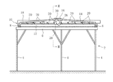
図1及び図2は、本発明の防振装置を備えた一実施例の振動コンベアを示す。
振動コンベアは架台2を備え、この架台2は複数の支持脚4と、これら支持脚4に支持されたアッパ枠6とからなる。アッパ枠6には4つの防振装置8を介してベッド10が支持されており、防振装置8はベッド10における矩形のベッドフレーム12の4隅に配置されている。なお、防振装置8については後述する。
FIG.1 and FIG.2 shows the vibration conveyor of one Example provided with the vibration isolator of this invention.
The vibration conveyor includes a
また、ベッド10はその両側に三角フレーム14をそれぞれ有する。これら三角フレーム14はベッドフレーム12の長辺ビームから上方に向けて立設され、その頂部にてクロス部材16により相互に連結されている。
更に、ベッドフレーム12の上方には、三角フレーム14間にトラフ18が配置されている。このトラフ18はベッド10の長手方向に延び、複数の加振ばね20を介してベッド10に支持されている。より詳しくは、各加振ばね20はリーフスプリングからなり、トラフ18の両側にて、ベッド10の長手方向に所定の間隔を存して配置され、その上下端がブラケット22,24(図2)を介してトラフ18及びベッドフレーム12に取り付けられている。
The
Further, a
図1から明らかなように各加振ばね20は所定の角度を存して傾斜し、ベッド10の長手方向に隣接する加振ばね20は平行四辺形の互いに対向する二辺を形成する。
各三角フレーム14の中央にはその外側に取り付け板26及びホルダ28を介して振動モータ30がそれぞれ取り付けられている。これら振動モータ30はその回転軸が加振ばね20と平行となるように傾斜して取り付けられ、回転軸の両端に取り付けれた偏心ウエイト(図示しない)の回転により、加振ばね20に対して直交する方向に加振力を発生する。より具体的には、振動モータ30はその加振力の作用線がトラフ18の重心を通過すべく配置されている。
As is apparent from FIG. 1, each
A
各振動モータ30が駆動されると、これら振動モータ30が発生する加振力は加振ばね20を介してトラフ18に伝達され、この結果、トラフ18が振動することで、トラフ18上の物品は一方向に搬送される。
上述したようにトラフ18重心は加振力の作用線上に存在しているので、振動モータ30の回転が同期回転数に維持されていれば、トラフ18の振動と振動モータ30の加振力とのバランスが確立され、加振力はトラフ18をリニア振動させるためのみに働く。この結果、トラフ18は理想的にリニア振動し、トラフ18の振動が防振装置8に伝達されることはない。
When each
As described above, since the center of gravity of the
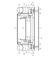
図2に示されるように、防振装置8はベッドフレーム12の長辺ビームから外側に突出したブラケット32(図2)とアッパ枠6との間に配置され、長辺ビーム及びアッパ枠6にそれぞれ取り付けられた上下のばね座34を有する。これらばね座34間には防振コイルばね36に加えて、円筒状減衰体としての弾性変形可能なゴムスプリング38が配置され、このゴムスプリング38は防振コイルばね36内にて同心的に位置付けられている。
As shown in FIG. 2, the
図3から明らかなようにゴムスプリング38は中空の円筒形状をなし、そして、防振コイルばね36に等しいか又は若干小さいばね定数を有する。
更に詳しくは、防振コイルばね36及びゴムスプリング38の自然高さHC,HGは等しく、そして、防振装置8は下側のばね座34と防振コイルばね36及びゴムスプリング38との間に挟み込まれたスペーサ37,39をそれぞれ有する。これらスペーサ37,39の厚みTC,TGは互いに異なり、この実施例の場合、TC>TGの関係を有する。
As is apparent from FIG. 3, the
More specifically, the natural heights H C and H G of the vibration-
従って、図4に示されるように防振装置8がアッパ枠6とベッドフレーム12との間に介装され、防振装置8にトラフ18側の重量が加わったとき、防振コイルばね36及びゴムスプリング38の収縮量、即ち、それらの静撓みは互い異なる。
なお、静撓みを互いに異ならせるには、上側のばね座34と防振コイルばね36及びゴムスプリング38との間にスペーサ37,39を挟み込んでもよいし、その一方のみを使用するだけでもよい。更に、防振コイルばね36及びゴムスプリング38の自然高さHC,HGが異なる場合には、スペーサ37,39を使用することなく、これらの静撓みを異ならせることができる。
Therefore, as shown in FIG. 4, when the
In order to make the static deflection different from each other, the
振動コンベアの起動時や運転停止時にあっては、振動モータ30の加振力とトラフ18の振動とのバランスが崩れ、ベッド10に大きな振動が発生するが、しかしながら、防振装置8は防振コイルばね36に加えてゴムスプリング38を備え、そして、これら防振コイルばね36及びゴムスプリング38の静撓みを互いに異ならせているから、防振コイルばね36の伸縮はゴムスプリング38により効果的に抑制され、防振コイルばね38の伸縮、つまり、ベッド10の振動を迅速に減衰させることができる。この結果、振動コンベアの起動時や運転停止時、ベッド10の振動が停止するまでに要する時間を大幅の短縮でき、ベッド10の安定した挙動特性を得ることができる。
When the vibration conveyor is started up or stopped, the balance between the vibration force of the
また、上述のゴムスプリング38は防振コイルばね36内に配置されているので、個々の防振装置8が大径化することもない。
更に、一実施例の振動コンベアの場合、一対の振動モータ30はベッド10の三角フレーム14に取り付けられているので、架台2のアッパ枠6からの振動コンベアの高さ寸法を低く抑えることができる。
Further, since the
Furthermore, in the case of the vibration conveyor of one embodiment, since the pair of
本発明の振動コンベアは上述した一実施例に制約されるものではなく、種々の変形が可能であり、図5に変形例の振動コンベアを示す。
変形例を説明するにあたり、一実施例の振動コンベアと同一の機能を有する部材及び部位には同一の参照符号を付し、それらの説明は省略する。
図5の振動コンベアの場合、前述した各加振ばね20はその傾斜角を調整可能にしてベッド10及びトラフ18に連結されている。即ち、ベッド10及びトラフ18からはピン52がそれぞれ突出されており、これらピン52に割溝を有するクランプ54がそれぞれ取付けられている。各クランプ54はその締付けねじ56によりピン52に対して回転不能に固定され、そして、対応する上下のクランプ54に加振ばね20の上下端がそれぞれ連結されている。
The vibration conveyor of the present invention is not limited to the above-described embodiment, and various modifications are possible. FIG. 5 shows a vibration conveyor according to a modification.
In describing the modification, members and parts having the same functions as those of the vibrating conveyor of one embodiment are denoted by the same reference numerals, and description thereof is omitted.
In the case of the vibration conveyor of FIG. 5, each of the
従って、クランプ54の締付けねじ56を緩め、ピン52の回りにクランプ54を回動させることで、加振ばね20の傾斜角を調整することができる。
更に、第3実施例の場合、振動モータ30のための取付け板58はベース10に対して昇降可能に取付けられている。そして、取付け板58からは一対のブラケット60が突設され、これらブラケット60間に振動モータ30のホルダ28がピン62を中心に回動可能に取付けられている。
Therefore, the inclination angle of the
Furthermore, in the case of the third embodiment, the
従って、前述した加振ばね20の傾斜角が調整されたとき、この調整に合わせるべく振動モータ30もまたピン62の回りに回動され、振動モータ30の加振力が作用する方向を加振ばね20に対して直交させることができる。そして、ベース10に対して取付け板58を昇降させることで、加振力の作用線上にトラフ18の重心を位置付けることができる。
Therefore, when the inclination angle of the
なお、本発明の振動コンベアは物品を単に搬送するものに限らず、トラフの一部に分級メッシュを使用することで、篩機能を持たせることも可能である。
更に、防振装置8のゴムスプリング38は防振コイルばね36を囲繞するように配置してもよいし、また、その形状も中空に限らず、中実の円筒形状であってもよい。更にまた、円筒状減衰体としてはゴムスプリングに限らず、防振コイルばね36と同様なコイルスプリングであってもよい。
The vibrating conveyor according to the present invention is not limited to the one that simply conveys articles, but can also have a sieving function by using a classification mesh for a part of the trough.
Furthermore, the
2 架台
8 防振装置
10 ベッド
12,50 ベッドフレーム
18,40 トラフ
20 加振ばね
30 振動モータ
34 ばね座
36 防振コイルばね
38 ゴムスプリング(円筒状減衰体)
2
Claims (4)
前記ばね座間に配置された防振コイルばねと、
前記ばね座間に前記防振コイルばねと同心的に配置され、前記防振コイルばねの伸縮を抑制する弾性変形可能な円筒状減衰体と、
前記防振コイルばね及び前記円筒状減衰体の少なくとも一方と前記ばね座との間に介挿され、前記一方の静撓みを調整するスペーサと
を具備したことを特徴とする防振装置。 Upper and lower spaced spring seats;
An anti-vibration coil spring disposed between the spring seats;
An elastically deformable cylindrical damping body that is concentrically disposed between the spring seats and concentrically with the anti-vibration coil spring, and suppresses expansion and contraction of the anti-vibration coil spring;
An anti-vibration device comprising: a spacer that is interposed between at least one of the anti-vibration coil spring and the cylindrical damping body and the spring seat, and adjusts the static deflection of the one.
前記架台に複数の防振装置を介して支持されたベッドと、
前記ベッドに複数の加振ばねを介して支持され、物品の搬送面を形成するトラフと、
前記ベッドに取り付けられ、前記加振ばねを介して前記トラフに加振力を加える一対の振動モータと
を具備し、
前記防振装置は、
前記架台と前記ベッドとの間に配置された防振コイルばねと、
前記架台と前記ベッドとの間に配置され、前記防振コイルばねの伸縮を抑制する弾性変形可能な円筒状減衰体と
を含み、
前記防振コイルばね及び前記円筒状減衰体は、前記トラフ側の重量を受けた状態にあるとき、静撓みが互いに異なっていることを特徴とする振動コンベア。 A frame,
A bed supported by the frame via a plurality of vibration isolation devices;
A trough supported by the bed via a plurality of vibration springs and forming a conveying surface of the article;
A pair of vibration motors attached to the bed and applying an excitation force to the trough via the excitation spring;
The vibration isolator is
An anti-vibration coil spring disposed between the gantry and the bed;
An elastically deformable cylindrical damping body that is disposed between the gantry and the bed and suppresses expansion and contraction of the anti-vibration coil spring;
The vibration conveyor, wherein the anti-vibration coil spring and the cylindrical damping body are different in static deflection when receiving the weight on the trough side.
Priority Applications (1)
| Application Number | Priority Date | Filing Date | Title |
|---|---|---|---|
| JP2005297618A JP2007106532A (en) | 2005-10-12 | 2005-10-12 | Vibration control device and vibratory conveyor |
Applications Claiming Priority (1)
| Application Number | Priority Date | Filing Date | Title |
|---|---|---|---|
| JP2005297618A JP2007106532A (en) | 2005-10-12 | 2005-10-12 | Vibration control device and vibratory conveyor |
Publications (1)
| Publication Number | Publication Date |
|---|---|
| JP2007106532A true JP2007106532A (en) | 2007-04-26 |
Family
ID=38032701
Family Applications (1)
| Application Number | Title | Priority Date | Filing Date |
|---|---|---|---|
| JP2005297618A Pending JP2007106532A (en) | 2005-10-12 | 2005-10-12 | Vibration control device and vibratory conveyor |
Country Status (1)
| Country | Link |
|---|---|
| JP (1) | JP2007106532A (en) |
Cited By (3)
| Publication number | Priority date | Publication date | Assignee | Title |
|---|---|---|---|---|
| JP2009243539A (en) * | 2008-03-29 | 2009-10-22 | Tokai Rubber Ind Ltd | Vibration damping device |
| CN102275717A (en) * | 2011-05-06 | 2011-12-14 | 常州常瑞天力动力机械有限公司 | Spring seat vibrating conveyor for engine lock block screening machine |
| JP2012076021A (en) * | 2010-10-01 | 2012-04-19 | Tipton Corp | Sorting apparatus |
Citations (3)
| Publication number | Priority date | Publication date | Assignee | Title |
|---|---|---|---|---|
| JPH05263761A (en) * | 1992-03-23 | 1993-10-12 | Sanyo Electric Co Ltd | Compressor supporting device |
| JP2004189380A (en) * | 2002-12-10 | 2004-07-08 | Shinko Electric Co Ltd | Two-mass system oscillation conveyor |
| JP2004324654A (en) * | 2002-12-24 | 2004-11-18 | Bridgestone Corp | Vibrationproof device |
-
2005
- 2005-10-12 JP JP2005297618A patent/JP2007106532A/en active Pending
Patent Citations (3)
| Publication number | Priority date | Publication date | Assignee | Title |
|---|---|---|---|---|
| JPH05263761A (en) * | 1992-03-23 | 1993-10-12 | Sanyo Electric Co Ltd | Compressor supporting device |
| JP2004189380A (en) * | 2002-12-10 | 2004-07-08 | Shinko Electric Co Ltd | Two-mass system oscillation conveyor |
| JP2004324654A (en) * | 2002-12-24 | 2004-11-18 | Bridgestone Corp | Vibrationproof device |
Cited By (3)
| Publication number | Priority date | Publication date | Assignee | Title |
|---|---|---|---|---|
| JP2009243539A (en) * | 2008-03-29 | 2009-10-22 | Tokai Rubber Ind Ltd | Vibration damping device |
| JP2012076021A (en) * | 2010-10-01 | 2012-04-19 | Tipton Corp | Sorting apparatus |
| CN102275717A (en) * | 2011-05-06 | 2011-12-14 | 常州常瑞天力动力机械有限公司 | Spring seat vibrating conveyor for engine lock block screening machine |
Similar Documents
| Publication | Publication Date | Title |
|---|---|---|
| JP4872221B2 (en) | Parts conveyor | |
| EP0881172A1 (en) | Excited base conveyor system | |
| TWI457264B (en) | Vibrating conveyor | |
| TWI516427B (en) | Parts feeder | |
| JP2007137674A (en) | Vibration type conveyance device | |
| KR101316490B1 (en) | Parts feeder | |
| KR20080097345A (en) | Vibratory conveying apparatus | |
| JP2012041107A (en) | Vibration-type component conveying device | |
| JP2007106532A (en) | Vibration control device and vibratory conveyor | |
| JP2002061703A (en) | Vibration control method and vibration control device using this vibration control method | |
| TWI686340B (en) | Linear feeder | |
| JP5070651B2 (en) | Linear feeder | |
| JP4977934B2 (en) | Elliptical vibratory feeder | |
| JP5168816B2 (en) | Parts supply device | |
| JP6010361B2 (en) | Resonant shaking table | |
| JPH11199026A (en) | Vibrating equipment | |
| JP4635120B2 (en) | Vibration reduction device for vibrating conveyor | |
| JPH03263810A (en) | Vibration control method of semiconductor aligner | |
| US20070209893A1 (en) | Vibration reduction system for mixers | |
| JPH076300B2 (en) | Floor vibration damping device | |
| JP5168999B2 (en) | Parts conveyor | |
| JP4590763B2 (en) | Linear feeder | |
| KR102018933B1 (en) | Vibration-type component transport device | |
| JP2017190211A (en) | Article conveyance device | |
| JP2002302231A (en) | Piezoelectric driving type vibrating feeder |
Legal Events
| Date | Code | Title | Description |
|---|---|---|---|
| A621 | Written request for application examination |
Free format text: JAPANESE INTERMEDIATE CODE: A621 Effective date: 20080205 |
|
| A977 | Report on retrieval |
Free format text: JAPANESE INTERMEDIATE CODE: A971007 Effective date: 20100611 |
|
| A131 | Notification of reasons for refusal |
Free format text: JAPANESE INTERMEDIATE CODE: A131 Effective date: 20100630 |
|
| A02 | Decision of refusal |
Free format text: JAPANESE INTERMEDIATE CODE: A02 Effective date: 20101027 |