JP2007023472A - Device for detecting parameter in two or more slivers fed to draft system of spinning machine - Google Patents
Device for detecting parameter in two or more slivers fed to draft system of spinning machine Download PDFInfo
- Publication number
- JP2007023472A JP2007023472A JP2006191854A JP2006191854A JP2007023472A JP 2007023472 A JP2007023472 A JP 2007023472A JP 2006191854 A JP2006191854 A JP 2006191854A JP 2006191854 A JP2006191854 A JP 2006191854A JP 2007023472 A JP2007023472 A JP 2007023472A
- Authority
- JP
- Japan
- Prior art keywords
- sliver
- distance sensor
- roller
- distance
- sensor
- Prior art date
- Legal status (The legal status is an assumption and is not a legal conclusion. Google has not performed a legal analysis and makes no representation as to the accuracy of the status listed.)
- Pending
Links
Images


Classifications
-
- D—TEXTILES; PAPER
- D01—NATURAL OR MAN-MADE THREADS OR FIBRES; SPINNING
- D01G—PRELIMINARY TREATMENT OF FIBRES, e.g. FOR SPINNING
- D01G31/00—Warning or safety devices, e.g. automatic fault detectors, stop motions
- D01G31/006—On-line measurement and recording of process and product parameters
-
- D—TEXTILES; PAPER
- D01—NATURAL OR MAN-MADE THREADS OR FIBRES; SPINNING
- D01G—PRELIMINARY TREATMENT OF FIBRES, e.g. FOR SPINNING
- D01G23/00—Feeding fibres to machines; Conveying fibres between machines
- D01G23/06—Arrangements in which a machine or apparatus is regulated in response to changes in the volume or weight of fibres fed, e.g. piano motions
-
- D—TEXTILES; PAPER
- D01—NATURAL OR MAN-MADE THREADS OR FIBRES; SPINNING
- D01H—SPINNING OR TWISTING
- D01H13/00—Other common constructional features, details or accessories
- D01H13/14—Warning or safety devices, e.g. automatic fault detectors, stop motions ; Monitoring the entanglement of slivers in drafting arrangements
- D01H13/16—Warning or safety devices, e.g. automatic fault detectors, stop motions ; Monitoring the entanglement of slivers in drafting arrangements responsive to reduction in material tension, failure of supply, or breakage, of material
- D01H13/1616—Warning or safety devices, e.g. automatic fault detectors, stop motions ; Monitoring the entanglement of slivers in drafting arrangements responsive to reduction in material tension, failure of supply, or breakage, of material characterised by the detector
- D01H13/1633—Electronic actuators
- D01H13/165—Photo-electric sensing means
-
- D—TEXTILES; PAPER
- D01—NATURAL OR MAN-MADE THREADS OR FIBRES; SPINNING
- D01H—SPINNING OR TWISTING
- D01H13/00—Other common constructional features, details or accessories
- D01H13/14—Warning or safety devices, e.g. automatic fault detectors, stop motions ; Monitoring the entanglement of slivers in drafting arrangements
- D01H13/22—Warning or safety devices, e.g. automatic fault detectors, stop motions ; Monitoring the entanglement of slivers in drafting arrangements responsive to presence of irregularities in running material
-
- D—TEXTILES; PAPER
- D01—NATURAL OR MAN-MADE THREADS OR FIBRES; SPINNING
- D01H—SPINNING OR TWISTING
- D01H13/00—Other common constructional features, details or accessories
- D01H13/32—Counting, measuring, recording or registering devices
-
- D—TEXTILES; PAPER
- D01—NATURAL OR MAN-MADE THREADS OR FIBRES; SPINNING
- D01H—SPINNING OR TWISTING
- D01H5/00—Drafting machines or arrangements ; Threading of roving into drafting machine
- D01H5/18—Drafting machines or arrangements without fallers or like pinned bars
- D01H5/32—Regulating or varying draft
-
- G—PHYSICS
- G01—MEASURING; TESTING
- G01B—MEASURING LENGTH, THICKNESS OR SIMILAR LINEAR DIMENSIONS; MEASURING ANGLES; MEASURING AREAS; MEASURING IRREGULARITIES OF SURFACES OR CONTOURS
- G01B5/00—Measuring arrangements characterised by the use of mechanical techniques
- G01B5/02—Measuring arrangements characterised by the use of mechanical techniques for measuring length, width or thickness
- G01B5/06—Measuring arrangements characterised by the use of mechanical techniques for measuring length, width or thickness for measuring thickness
- G01B5/068—Measuring arrangements characterised by the use of mechanical techniques for measuring length, width or thickness for measuring thickness of objects while moving
Abstract
Description
本発明は、紡機の牽伸システムに送給された複数本のスライバにおけるパラメータを検出する装置であって、特にスライバの移動および/または存在を検出し、上記パラメータは各スライバにおいて別個に測定可能であり、各スライバはスライバ用ケンスから夫々の被動供給ローラ上へと引出されると共に上記牽伸システムに送給されて触覚要素により機械的に検知され、該触覚要素の偏向は電気信号へと変換可能であると共に該触覚要素は自身に関係付けられたセンサ要素を有するという装置に関する。 The present invention is a device for detecting parameters in a plurality of slivers fed to a drafting system of a spinning machine, in particular, detecting movement and / or presence of slivers, and the parameters can be measured separately in each sliver. Each sliver is drawn from the sliver can onto a respective driven supply roller and fed to the drafting system where it is mechanically detected by the haptic element, and the deflection of the haptic element is converted into an electrical signal. It relates to a device that is translatable and that the tactile element has a sensor element associated with it.
公知の装置(WO 98/18985 A)の場合には、8本のスライバに対し、牽伸システムから見て上流に、複数個の案内ローラ、ならびに、8個の測定要素および8個のケンスが配備されている。全ての測定要素は、リード線によりコンピュータに対して並列に接続される。上記測定要素は各々、被動ローラと、回転軸心の回りで変位可能なレバー上に取付けられた従動ロールとを備える。上記ローラはスライバに対する溝を有し、該溝はスライバを検知するために上記ロールによっても係合され得る。上記練篠システムに進入する各スライバは、パラメータを検出するために測定要素において予め検知される。可能的なパラメータは好適には、絶対値の形態の重量、太さ、質量などであるか、または、相対値、例えば重量、太さもしくは質量における変化である。このプロセスにおいて上記ロールは上記ローラ上のスライバにより占有された体積部分により偏向され、この偏向は該偏向に比例する出力信号へと変換される。全ての測定要素の出力信号は、上記リード線を介して上記コンピュータに送給される。各測定値はスレッショルド値と比較されることで、スライバが実際に存在すること、または、スライバが最小体積に到達したことが確認される。舌部および溝ローラから成るこの機械的感知システムによるこの動的関係は、高い吐出速度にては十分ではない。上記触覚ローラは、大きな質量により揺動(oscillate)せしめられることがある。 In the case of the known device (WO 98/18985 A), for 8 slivers, there are a plurality of guide rollers, 8 measuring elements and 8 cans upstream from the drafting system. Has been deployed. All measuring elements are connected in parallel to the computer by leads. Each of the measuring elements comprises a driven roller and a driven roll mounted on a lever that is displaceable about a rotational axis. The roller has a groove for the sliver, which can also be engaged by the roll to detect the sliver. Each sliver entering the Nershino system is sensed in advance in the measuring element in order to detect parameters. Possible parameters are preferably weight, thickness, mass etc. in the form of absolute values, or changes in relative values, eg weight, thickness or mass. In this process, the roll is deflected by the volume occupied by the sliver on the roller, and this deflection is converted into an output signal proportional to the deflection. The output signals of all measuring elements are sent to the computer via the lead wires. Each measurement is compared with a threshold value to confirm that the sliver is actually present or that the sliver has reached a minimum volume. This dynamic relationship with this mechanical sensing system consisting of tongues and groove rollers is not sufficient at high discharge speeds. The tactile roller may be oscillated by a large mass.
故に本発明は、冒頭部分に記述された種類の装置であって、上記不都合を回避し、特に構造が簡素であると共に個々のスライバを更に良好にかつ更に正確に検出し得る装置を実現するという課題に基づいている。 Therefore, the present invention is an apparatus of the type described at the beginning, which avoids the above disadvantages and realizes an apparatus that is particularly simple in structure and can detect individual slivers better and more accurately. Based on challenges.
上記課題は、請求項1の特徴部分の特徴により解決される。
すなわち、1番目の発明によれば、紡機の牽伸システムに対して送給された複数本のスライバにおけるパラメータを検出する装置であって、特にスライバの移動および/または存在を検出し、上記パラメータは各スライバにおいて別個に測定可能であり、各スライバはスライバ用ケンスから夫々の被動供給ローラ上へと引出されると共に上記牽伸システムに送給されて触覚要素により機械的に検知され、該触覚要素の偏向は電気信号へと変換可能であると共に該触覚要素は自身に関係付けられたセンサ要素を有するという装置において、各触覚要素(9;9a〜9f、19;19a、19b、19c)の位置を検出する非接触式距離センサ(20;20a〜20f)(距離測定センサ)が設けられており、これら非接触式距離センサ(20;20a〜20f)は電気的評価デバイス(38)に接続されることを特徴とする、装置が提供される。
The above problem is solved by the features of the characterizing portion of claim 1.
That is, according to the first invention, there is provided a device for detecting parameters in a plurality of slivers fed to a drafting system for a spinning machine, particularly detecting movement and / or presence of the sliver, Can be measured separately at each sliver, and each sliver is drawn from the sliver can onto a respective driven supply roller and fed to the drafting system where it is mechanically detected by the tactile element, In a device in which the deflection of the element can be converted into an electrical signal and the haptic element has a sensor element associated with it, each haptic element (9; 9a-9f, 19; 19a, 19b, 19c) Non-contact distance sensors (20; 20a to 20f) (distance measuring sensors) for detecting positions are provided, and these non-contact distance sensors (20; 0A~20f) is characterized in that it is connected to an electrical evaluation device (38), an apparatus is provided.
本発明に係る非接触式距離センサ(距離を測定するセンサ)に依れば、構造的に簡素な様式で個々のスライバを更に良好にかつ更に正確に検出することが許容される。好適には、上記光学的距離センサの測定点は、たとえば運動可能に取付けられた圧力ロール・アーム上に配置される。初期始動(機械は停止)時に、上記圧力ロールはスライバなしで上記送給ローラ上に載置され、上記圧力ロールまでの距離が測定されて制御ユニットに記憶される。上記機械を停止し乍ら、次に上記圧力ロールと送給ローラとの間にスライバが載置される。スライバの太さにより上記距離センサと圧力ロールとの間の距離が減少され、上記制御ユニットは定常的に存在する信号を検出する。この信号は初期の始動時における値と比較されて、静止的なスライバが存在することが確立される。スライバが存在すること又は交換されたスライバが認識されることを確実にするために、存在するスライバによるこの測定は、上記機械が投入切換えされる前に自動的に常に行われるべきである。スライバの搬送(機械の運転)により、上記圧力ロールは今や持続的に揺動され、その結果としての距離の変動が検出され、連続的に改変可能な信号が測定され、上記制御ユニットは運動するスライバが存在することを検出する。もしスライバが裂断したなら、上記圧力ロールは上記送給ローラ上のスライバなしで運転され、測定信号は始動時の上記信号と比較され、始動時における測定値が検出されると共に、それを関数”機械運転”と組み合わせることで、上記制御ユニットは上記機械がスライバの存在なしで運転されていることを認識する。各信号を組み合わせることで上記制御ユニットが、上記機械は”動作の準備ができていない”ことを検出するという記述状態の全てにおいて、上記機械は動作不良であり作動停止される。プログラム技術により上記機械の関数と組み合わされて評価されるこれらの種々の信号を測定することにより、正確で間接的な光学的/超音波的距離測定に基づきローラ取入口における個々のスライバの効率的な監視が達成され得る。スライバ較正の夫々の個別値は、(たとえばスライバ監視に関する統計値すなわち変化可能な測定パラメータなどを用いる)プログラミングにより更に処理され得る。 The non-contact distance sensor (sensor for measuring distance) according to the present invention allows for better and more accurate detection of individual slivers in a structurally simple manner. Preferably, the measuring point of the optical distance sensor is arranged, for example, on a pressure roll arm that is movably mounted. At the initial start (the machine is stopped), the pressure roll is placed on the feed roller without a sliver, and the distance to the pressure roll is measured and stored in the control unit. While the machine is stopped, a sliver is then placed between the pressure roll and the feed roller. The distance between the distance sensor and the pressure roll is reduced by the thickness of the sliver, and the control unit detects a signal that exists constantly. This signal is compared with the value at initial start-up to establish that a stationary sliver is present. In order to ensure that the sliver is present or that the replaced sliver is recognized, this measurement by the existing sliver should always be made automatically before the machine is switched on. Due to the sliver transport (machine operation), the pressure roll is now continuously swung, the resulting distance variation is detected, the continuously modifiable signal is measured, and the control unit moves Detects the presence of a sliver. If the sliver breaks, the pressure roll is operated without the sliver on the feed roller, the measurement signal is compared with the signal at start-up, and the measured value at start-up is detected and is used as a function. In combination with "machine operation", the control unit recognizes that the machine is operating without the presence of a sliver. In combination with the signals, the control unit detects that the machine is “not ready for operation” and in all the described states, the machine is malfunctioning and is deactivated. By measuring these various signals, which are evaluated in combination with the machine functions by means of programming techniques, the efficiency of individual slivers at the roller inlet based on accurate and indirect optical / ultrasonic distance measurements. Monitoring can be achieved. Each individual value of the sliver calibration can be further processed by programming (eg, using sliver monitoring statistics or variable measurement parameters, etc.).
請求項2乃至50は、本発明の更なる好適な見地を包含している。
すなわち2番目の発明によれば、1番目の発明において、前記距離センサは、波または光線を用いて距離を測定するセンサである。
3番目の発明によれば、1番目または2番目の発明において、前記距離センサは光学的または音響的な距離測定センサである。
4番目の発明によれば、1番目から3番目のいずれかの発明において、超音波距離センサ(距離測定センサ)が使用される。
5番目の発明によれば、1番目から4番目のいずれかの発明において、光線または音線が焦点合わせされる。
6番目の発明によれば、1番目から5番目のいずれかの発明において、前記距離センサは光走査器である。
7番目の発明によれば、1番目から6番目のいずれかの発明において、前記距離センサは送信器および受信器から成る。
8番目の発明によれば、1番目から7番目のいずれかの発明において、前記距離センサはレーザ走査器である。
9番目の発明によれば、1番目から8番目のいずれかの発明において、前記距離センサは可視光線を使用する。
10番目の発明によれば、1番目から9番目のいずれかの発明において、前記距離センサは赤外光を使用する。
11番目の発明によれば、1番目から10番目のいずれかの発明において、前記距離センサは前記触覚要素までの距離を決定する。
12番目の発明によれば、1番目から11番目のいずれかの発明において、前記距離センサは、前記触覚要素と組み合わされた対向要素までの距離を決定する。
13番目の発明によれば、1番目から12番目のいずれかの発明において、前記距離センサは固定され、前記対向要素は該距離センサに対して運動可能である。
14番目の発明によれば、1番目から13番目のいずれかの発明において、前記距離センサは運動可能であり、前記対向要素は該距離センサに対して固定される。
15番目の発明によれば、1番目から14番目のいずれかの発明において、前記対向要素は平坦な走査表面を有する。
16番目の発明によれば、1番目から15番目のいずれかの発明において、前記対向要素は円滑な走査表面を有する。
17番目の発明によれば、1番目から16番目のいずれかの発明において、前記対向要素は湾曲した走査表面を有する。
18番目の発明によれば、1番目から17番目のいずれかの発明において、前記走査表面は反射的である。
19番目の発明によれば、1番目から18番目のいずれかの発明において、前記評価ユニットは開ループ/閉ループ制御デバイスに接続される。
20番目の発明によれば、1番目から19番目のいずれかの発明において、前記距離センサはアナログ・センサである。
21番目の発明によれば、1番目から20番目のいずれかの発明において、前記信号は測定点から評価ユニットまで光学的導波路を用いて導かれる。
22番目の発明によれば、1番目から21番目のいずれかの発明において、前記距離センサは可動触覚舌部の偏位を走査する。
23番目の発明によれば、1番目から22番目のいずれかの発明において、前記距離センサは可動触覚ローラの偏位を走査する。
24番目の発明によれば、1番目から23番目のいずれかの発明において、前記距離センサは前記触覚舌部または前記触覚ローラの偏位を直接的または間接的に走査する。
25番目の発明によれば、1番目から24番目のいずれかの発明において、当該装置はスライバの破断を確認して表示するために使用される。
26番目の発明によれば、1番目から25番目のいずれかの発明において、当該装置はスライバの運動を確認または表示するために使用される。
27番目の発明によれば、1番目から26番目のいずれかの発明において、前記距離センサは、長寸であって概ね撚り合わせられていない繊維束のパラメータを決定するために使用される。
28番目の発明によれば、1番目から27番目のいずれかの発明において、前記距離センサは、連続的に移動する繊維束によるパラメータを測定するために使用される。
29番目の発明によれば、1番目から28番目のいずれかの発明において、前記スライバ質量に対して決定された値は、前記繊維束が練篠されつつある紡績用前処理機の少なくとも一個の牽伸要素を制御することによって上記繊維束のスライバ質量変動を調節するために使用される。
30番目の発明によれば、1番目から29番目のいずれかの発明において、前記触覚要素は固定された回動軸受上に取付けられる。
31番目の発明によれば、1番目から30番目のいずれかの発明において、前記触覚要素は回動可能取付けられたレバーである。
32番目の発明によれば、1番目から31番目のいずれかの発明において、前記触覚要素は、たとえば平衡錘、スプリングなどの力付与要素と協働する。
33番目の発明によれば、1番目から32番目のいずれかの発明において、前記触覚要素は水平方向に可動であるべく取付けられる。
34番目の発明によれば、1番目から33番目のいずれかの発明において、前記触覚要素は一端にて弾性的に取付けられる。
35番目の発明によれば、1番目から34番目のいずれかの発明において、前記触覚要素は、たとえばレバーなどの保持部材上に取付けられる。
36番目の発明によれば、1番目から35番目のいずれかの発明において、前記触覚要素は鉛直軸心の回りで回動可能に取付けられる。
37番目の発明によれば、1番目から36番目のいずれかの発明において、可動的に取付けられた前記触覚要素は、たとえばスプリング、重り、自然弾性、負荷シリンダ、磁石などの機械的、電気的、油圧的または空気的な手段により付勢されると共に調節可能とされ得る。
38番目の発明によれば、1番目から37番目のいずれかの発明において、複数個の距離センサが配備され、その各々は触覚要素によってスライバの太さを走査する(個別スライバ走査)。
39番目の発明によれば、1番目から38番目のいずれかの発明において、前記スライバは、入力部分において紡績用ケンスから複数の被動送給ローラ上へと引出されて、被動牽伸システムへと搬送される。
40番目の発明によれば、1番目から39番目のいずれかの発明において、前記送給ローラは固定される。
41番目の発明によれば、1番目から40番目のいずれかの発明において、各送給ローラ上には運動可能(偏向可能)な共回転ローラが位置する。
42番目の発明によれば、1番目から41番目のいずれかの発明において、前記運動可能ローラは回転式レバーにより回転式軸受上に取付けられる。
43番目の発明によれば、1番目から42番目のいずれかの発明において、前記距離センサは前記運動可能ローラおよび/または少なくとも一本の回転式レバーの偏向を検出し得る。
44番目の発明によれば、1番目から43番目のいずれかの発明において、前記距離センサと共に前記触覚要素は前記ケンスの出力部に配備される。
45番目の発明によれば、1番目から44番目のいずれかの発明において、前記距離センサと共に前記触覚要素は前記ケンスからスライバを取出す配置機構の一部を形成する。
46番目の発明によれば、1番目から45番目のいずれかの発明において、前記共回転ローラ(圧点)は自身の重量下で前記送給ローラ上に位置する。
47番目の発明によれば、1番目から46番目のいずれかの発明において、前記評価デバイスは多重チャネル評価デバイスから成る。
48番目の発明によれば、1番目から47番目のいずれかの発明において、各距離センサは個別に停止切換えされるべく配置される。
49番目の発明によれば、1番目から48番目のいずれかの発明において、前記送給ローラと前記共回転ローラ(圧力ロール)との2つの円筒状周囲表面の間にはローラ・ニップが在る。
50番目の発明によれば、1番目から49番目のいずれかの発明において、前記繊維束を搬送するときに前記圧力ロールは持続的に揺動する。
Claims 2 to 50 include further preferred aspects of the present invention.
That is, according to the second invention, in the first invention, the distance sensor is a sensor for measuring a distance using a wave or a light beam.
According to a third aspect, in the first or second aspect, the distance sensor is an optical or acoustic distance measuring sensor.
According to the fourth invention, in any one of the first to third inventions, an ultrasonic distance sensor (distance measuring sensor) is used.
According to the fifth aspect, in one of the first to fourth aspects, the light beam or the sound ray is focused.
According to a sixth invention, in any one of the first to fifth inventions, the distance sensor is an optical scanner.
According to a seventh invention, in any one of the first to sixth inventions, the distance sensor comprises a transmitter and a receiver.
According to an eighth invention, in any one of the first to seventh inventions, the distance sensor is a laser scanner.
According to a ninth invention, in any one of the first to eighth inventions, the distance sensor uses visible light.
According to a tenth aspect, in any one of the first to ninth aspects, the distance sensor uses infrared light.
According to an eleventh aspect, in any one of the first to tenth aspects, the distance sensor determines a distance to the tactile element.
According to a twelfth aspect, in any one of the first to eleventh aspects, the distance sensor determines a distance to the opposing element combined with the tactile element.
According to a thirteenth aspect, in any one of the first to twelfth aspects, the distance sensor is fixed, and the opposing element is movable with respect to the distance sensor.
According to a fourteenth invention, in any one of the first to thirteenth inventions, the distance sensor is movable, and the opposing element is fixed with respect to the distance sensor.
According to a fifteenth aspect, in any one of the first to fourteenth aspects, the opposing element has a flat scanning surface.
According to a sixteenth aspect, in any one of the first to fifteenth aspects, the facing element has a smooth scanning surface.
According to a seventeenth aspect, in any one of the first to sixteenth aspects, the opposing element has a curved scanning surface.
According to an eighteenth aspect of the invention, in any one of the first to seventeenth aspects, the scanning surface is reflective.
According to a nineteenth invention, in any of the first to eighteenth inventions, the evaluation unit is connected to an open loop / closed loop control device.
According to a twentieth invention, in any one of the first to nineteenth inventions, the distance sensor is an analog sensor.
According to the twenty-first aspect, in any of the first to twentieth aspects, the signal is guided from the measurement point to the evaluation unit using an optical waveguide.
According to the twenty-second aspect, in any one of the first to twenty-first aspects, the distance sensor scans the displacement of the movable tactile tongue.
According to the twenty-third aspect, in any one of the first to twenty-second aspects, the distance sensor scans the displacement of the movable tactile roller.
According to a twenty-fourth aspect, in any one of the first to twenty-third aspects, the distance sensor scans the displacement of the haptic tongue or the haptic roller directly or indirectly.
According to the twenty-fifth aspect, in any one of the first to twenty-fourth aspects, the device is used for confirming and displaying the breakage of the sliver.
According to the twenty-sixth aspect, in any one of the first to twenty-fifth aspects, the device is used for confirming or displaying the movement of the sliver.
According to a twenty-seventh aspect, in any of the first to twenty-sixth aspects, the distance sensor is used to determine a parameter of a fiber bundle that is long and not generally twisted.
According to the 28th invention, in any one of the 1st to 27th inventions, the distance sensor is used to measure a parameter due to a continuously moving fiber bundle.
According to the twenty-ninth invention, in any one of the first to twenty-eighth inventions, the value determined for the sliver mass is at least one of the spinning pretreatment machines in which the fiber bundle is being squeezed It is used to adjust the sliver mass variation of the fiber bundle by controlling the drafting element.
According to the 30th invention, in any one of the 1st to 29th inventions, the tactile element is mounted on a fixed rotation bearing.
According to a thirty-first aspect, in any one of the first to thirtieth aspects, the tactile element is a lever that is pivotally attached.
According to a thirty-second aspect, in any one of the first to thirty-first aspects, the tactile element cooperates with a force applying element such as a balance weight or a spring.
According to the thirty-third aspect, in any one of the first to thirty-second aspects, the haptic element is attached so as to be movable in the horizontal direction.
According to a thirty-fourth aspect, in any one of the first to thirty-third aspects, the haptic element is elastically attached at one end.
According to a thirty-fifth aspect, in any one of the first to thirty-fourth aspects, the tactile element is mounted on a holding member such as a lever.
According to a thirty-sixth aspect, in any one of the first to thirty-fifth aspects, the tactile element is attached to be rotatable about a vertical axis.
According to the thirty-seventh aspect, in any one of the first to thirty-sixth aspects, the haptic element that is movably attached includes, for example, a mechanical, electrical device such as a spring, a weight, natural elasticity, a load cylinder, or a magnet. It can be biased and adjustable by hydraulic or pneumatic means.
According to the thirty-eighth invention, in any one of the first to thirty-seventh inventions, a plurality of distance sensors are provided, each of which scans the thickness of the sliver by a tactile element (individual sliver scanning).
According to the thirty-ninth invention, in any one of the first to thirty-eighth inventions, the sliver is pulled out from the spinning cane onto the plurality of driven feeding rollers at the input portion to the driven drafting system. Be transported.
According to the 40th invention, in any one of the 1st to 39th inventions, the feeding roller is fixed.
According to the 41st invention, in any one of the 1st to 40th inventions, a movable (deflable) co-rotating roller is located on each feeding roller.
According to a forty-second invention, in any of the first to forty-first inventions, the movable roller is mounted on a rotary bearing by a rotary lever.
According to the 43rd invention, in any of the 1st to 42nd inventions, the distance sensor can detect the deflection of the movable roller and / or at least one rotary lever.
According to a 44th aspect, in any one of the first to 43rd aspects, the tactile element together with the distance sensor is arranged at the output of the can.
According to a 45th aspect, in any one of the first to 44th aspects, the tactile element together with the distance sensor forms part of an arrangement mechanism for taking out a sliver from the can.
According to a 46th aspect, in any of the first to 45th aspects, the co-rotating roller (pressure point) is positioned on the feeding roller under its own weight.
According to a 47th aspect, in any one of the first to 46th aspects, the evaluation device comprises a multi-channel evaluation device.
According to the forty-eighth invention, in any of the first to 47th inventions, each distance sensor is arranged to be stopped and switched individually.
According to the 49th invention, in any of the first to 48th inventions, there is a roller nip between two cylindrical peripheral surfaces of the feeding roller and the co-rotating roller (pressure roll). The
According to the 50th invention, in any one of the 1st to 49th inventions, when the fiber bundle is conveyed, the pressure roll continuously swings.
本発明は、図面に示された好適実施例に関して以下に詳細に説明される。
図1に係る側面図は、たとえばTruetzschler練篠フレームTD 03などの練篠フレームの入力領域1、送給領域2、牽伸システム3およびスライバ巻取り領域4を示している。入力領域1においては、スライバ案内プレート(軸架[creel])の下方において練篠フレームの3個の紡績用ケンス5a〜5c(丸形のケンス)が2列のケンスを以て配置され(図2参照)、且つ、送給スライバ7a〜7cは送給ローラ8a〜8c上へと引出されて練篠フレーム3に供給される。共回転する頂部ローラ9a〜9cが夫々の被動送給ローラ8a〜8cに組み合わされる。送給テーブル領域においては、各対が頂部ローラおよび送給ローラを備える6つのローラ対8、9が存在する(図2参照)。スライバ7a〜7cは、紡績用ケンス5a〜5cから揚動されると共に、送給テーブル6上において牽伸システム3まで案内される。牽伸システム3を通過した後、引出されたスライバ7’はケンス用巻取器(カンコイラ)の回転プレートに進入すると共に、吐出側ケンス内にコイル状に布置される。送給テーブル6は、上記スライバ送給デバイス全体の領域を横切って上記練篠フレームまで延在する。スライバ7が各紡績用ケンス5から上記スライバ送給デバイスを介して上記練篠フレームまで供給される。各々がローラ対8a、9a;8b、9b;8c、9c(ローラ取入口)を備えるという夫々のスライバ送給点を通じて送給作用が行われる。各下側ローラ8a〜8cの領域においては、スライバ7を案内する夫々の案内要素が配備される。記号Aは、スライバ7a、7bおよび7cの進行方向を表している。スライバ7a〜7cは、ローラ対8、9間に圧搾される。送給ローラ8a〜8cおよび頂部ローラ9a〜9cの回転方向は、夫々の湾曲矢印により表される。各送給ローラ8は駆動手段に接続される。送給テーブル6の出力部には、スライバ7a〜7fに対する案内デバイスが存在しており、この案内デバイスは円筒状の断面を有すると共に8個の円筒体11a〜11hが後側に固着された水平バー10を含んでいる。円筒体11a〜11hの軸心は鉛直方向に整列され、円筒体11a〜11hの円筒体ケーシング間の間隔は、夫々のスライバ7a〜7fが阻害されることなく通過するのに十分なほど大寸である。この手段により、頂部が開放した案内溝がスライバ7a〜7fのために形成され、すなわち、円筒体11a〜11hは案内要素として機能する。送給テーブル6に続いては、練篠フレームに対する入力部にて、たとえば2個の張設用底部ローラ12a、12bおよび1個の張設用頂部ローラ13である被動ローラ配置機構が存在する。
The present invention will be described in detail below with reference to the preferred embodiments shown in the drawings.
The side view according to FIG. 1 shows an input area 1, a feeding area 2, a
図2に示された如く送給テーブル6の各側部においては、3個の紡績用ケンス5(不図示)の列が互いに平行に設定される。作動時には、スライバ7は6個の紡績用ケンスの各々から同時に引出され得る。あるいは、動作の様式は、たとえばスライバ7が3個の紡績用ケンス5a〜5cから一側においてのみ引出されると共に、他側においては3個の紡績用ケンス5d〜5fが交換中であってもよい。更に送給テーブル6の各側においては、作用方向Aにおいて順番に三つの送給ローラ8a、8b、8cおよび8d、8e、8fがそれぞれ配置される。2つの送給ローラ8a、8d;8b、8e;8c、8fのそれぞれは互いに同軸に配置される。送給ローラ8a〜8fは、同一の直径、たとえば100mmの直径を有する。各送給ローラの回転速度nは作用方向Aにおいて減少し、すなわちn1>n2>n3である。故に各送給ローラ8の円周速度Uは、上記作用方向において減少する。故に各送給ローラ8の円周速度U1、U2、U3を調節し、それにより、全てのスライバ7の入力張力を所望のようにすることができる。各送給ローラ8は(不図示の)ギヤ機構または同様の伝達デバイスにより駆動される。(不図示の)ベルトを介して駆動力を送給ローラ8a〜8fに伝達する可変速度モータ31(図6参照)が駆動のために用いられる。送給ローラ8の各々は、(それ自体公知の様式で)二部材式構成であると共に、互いに異なる長さである。入力領域1における各スライバ7の長さは内側から外側にかけて減少する。図1、図2に依ると、スライバ7a〜7fは入力領域1の送給テーブル6から、案内デバイス(ロッド10、円筒体11a〜11f)を介し、張設ローラ配置機構12、13と、搬送ローラ15および16を備えた(測定デバイスを含む)スライバ案内部材14とを通り、牽伸システム3とウェブ案内部材27と吐出ローラ28、29を備えたスライバ・ファネル30と回転プレート41とを通り、ケンス42内へと進行する。
As shown in FIG. 2, at each side of the feeding table 6, a row of three spinning cans 5 (not shown) is set in parallel to each other. In operation, the
図2は、全てが下側に配置されたローラ8a〜8f、12a、12b、15、III、IIおよびIを示している。図2に依れば、ローラ対8、9と張設ローラ配置機構12、13との間の領域において6本のスライバ7を含む繊維束は入力軸架張力を受けており、張設ローラ配置機構12、13と搬送ローラ15、16との間の領域において6本のスライバ7を含む繊維束は張設ローラの張力を受けており、且つ、搬送ローラ15、16と牽伸システム3の送給ローラ26、IIIとの間の領域において6本のスライバ7を含む繊維束は搬送ローラの張力を受けている。
FIG. 2 shows the
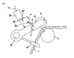
図3を参照すると、たとえばスライバ7a’は、方向Bにおいてケンス5aから引出され、スライバ案内部材43の開口部(挿通用鳩目)を貫通して方向Aに進路変更され、最終的にはスライバ7a”の形態で、被動送給ローラ8および共回転する頂部ローラ9の間のローラ・ニップを通過する。頂部ローラ9は回動可能な加重レバー19の一端に回転可能に固着される。加重レバー19の他端はスライバ送給テーブル6上に取付けられた静止的な支持バー18に固着される。加重レバー19は矢印C、Dの方向に回動可能である。保持要素44を介して支持バー18に固定的に固着された光走査器20が距離センサとして加重レバー19の上方に配備される。図4に依れば、距離センサ20(光センサ)は光送信器20’および光受信器20”から成る。光送信器20’により発せられた光線201は加重レバー19の円滑表面により反射され、反射された光線202は光受信器20”により受信される。参照番号17は電気リード線を表し、距離センサ20はこのリード線を通じて評価ユニット(図6における電子的制御/調整デバイス38を参照)に接続される。文字”a”は、一方では光送信器20’と光受信器20”との間の距離、他方では光送信器20’と加重レバー19との間の距離を表している。
Referring to FIG. 3, for example, the
図5に依ると、各加重レバー19a、19b、19cには、夫々の光走査器20a、20b、20cが組み合わされる。光走査器20a、20bおよび20cは夫々のライン17a、17b、17cを介して、電子的評価手段として作用する制御/調整デバイス38(図6参照)に接続される。リード線17a、17b、17cは、電気パルスを伝達する。
According to FIG. 5, each
リード線17a、17b、17cは、光ファイバ・ケーブルの形態であってもよい。その場合、光パルスを電気パルスに変換する(不図示の)信号変換器を各光走査器20と開ループ/閉ループ制御器との間に配置する必要がある。
The
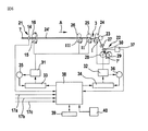
図6に依ると、上記練篠フレームは牽伸システム3を備え、その上流には牽伸システム取入口21が配置されると共に下流には牽伸システム吐出口22が配置されている。取出しローラ15、16により引出された各スライバ7は、測定要素14を通過して搬送される。牽伸システム3はフォー・オーバー・スリー牽伸システムとして設計され、すなわち該システムは、3個の底部ローラI、II、III(Iは底部吐出ローラ、IIは中央底部ローラ、および、IIIは底部送給ローラ)と、4個の頂部ローラ23、24、25、26とから成る。数本のスライバ7a〜7fから成る繊維束7の牽伸作用は牽伸システム3において行われる。牽伸システムは、予備牽伸部および主要牽伸部から成る。ローラ対26/IIIおよび25/IIは予備牽伸領域を形成し、ローラ対25/IIおよび23、24/Iは主要牽伸領域を形成する。引出されたスライバ7は牽伸システム吐出口22におけるウェブ案内部材27に到達して、スライバ・ファネル30を通して吐出ローラ28、29により引出される。スライバ・ファネル30においてはスライバ7はスライバ7’へと集束され、該スライバは引き続きケンス42内へと布置される。歯付きベルトを介して機械的に結合された取出ローラ15、16、底部送給ローラIIIおよび中央底部ローラIIは、所望の値が予め設定され得る可変速度モータ31により駆動される(関係付けられた頂部ローラ26および25は共回転する)。底部吐出ローラIおよび吐出ローラ28、29は主要モータ32により駆動される。可変速度モータ31および主要モータ32の各々は自身の閉ループ・システム33、34を有する。制御(速度制御)は閉制御ループにより行われ、タコジェネレータ35が上記可変速度モータに組み合わされており、タコジェネレータ36が主要モータ32に組み合わされる。上記牽伸システムの吐出口22においては、出現するスライバ7’の質量に比例するたとえば断面積などの変数が、スライバ・ファネル30に組み合わされた吐出測定要素37から獲得される。たとえばマイクロプロセッサを備えたマイクロコンピュータである中央処理ユニット38(開ループ/閉ループ制御器)は、可変速度モータ31に対する所望の変数の設定をコントローラ33に伝達する。測定要素14の測定済み変数は、牽伸操作の間において上記中央処理ユニットに伝達される。可変速度モータ31のために処理された値は、測定要素14からの測定済み変数と、出現するスライバ7’の断面積に対する所望値とに基づいて、中央処理ユニット38にて決定される。吐出測定要素37の測定済み変数は、出現するスライバ7’を監視する役目を果たす(出力スライバ監視)。この制御システムを用いると、ケンス内に送給されるスライバ7の断面積の変動は、予備牽伸プロセスの対応した調整作用により補償され得ると共に、スライバ7’は均一化され得る。参照番号39は入力デバイスを表し、且つ、参照番号40はたとえば視覚的表示ユニットなどの表示手段を表す。17a、17b、17cは、図5に示された如く光走査器20a、20bおよび20cを処理ユニット38(評価ユニット)に夫々接続するリード線を表す。
According to FIG. 6, the training frame includes a
図6は、オートレベラの例を用いて記述された。非調整式の練篠フレームも包含される。 FIG. 6 was described using an auto-leveler example. Non-adjustable Nershino frames are also included.
(最大で8本である)スライバ7は、送給軸架6に取付けられた練篠フレームを通じてケンス5から該送給軸架上へと引出される。該ローラ軸架は主として、2個の支持体および1本のビームを備えて成る。送給ローラが支持バー18および圧力ロール9によってこのビーム上に取付けられている。送給ローラ8は、上記練篠フレームにより駆動される。スライバ案内部材43と、圧力ロール9を備えた支持バー18とが送給ローラに取付けられる。安定化させるために、スライバ7はまずスライバ案内部材43を通じて案内され、次いで上記練篠フレームに向けて被動送給ローラ8上を案内される。可動アーム19を介して支持バー18に接続された圧力ロール9が該スライバ7上に位置すると共にその比較的に大きい自重の故に圧力ロール9が該スライバ7を送給ローラ8上に押圧するときにのみ、スライバ7は送給ローラ8により搬送され得る。故にスライバ7は、送給ローラ8と圧力ロール9との間で一定度合いまで加圧される。圧力ロール9は回転可能に取付けられており、それにより、スライバ7は損傷を蒙ることなしに移動されるようになる。
The sliver 7 (the maximum number is 8) is pulled out from the can 5 onto the feed shaft through a training frame attached to the
圧力ロール9と共に存在する支持バー18上に距離センサ、たとえば(選択的に光ファイバ・ケーブルと共に)光学的距離センサ20などを取付けることにより、圧力ロール9に対する距離測定を行って結果的にスライバの状態を検出することが可能である。その利点は、個々のスライバに対して、完全に機械的に離間された非接触式の監視が個別に行えることである。以下に記述される動作状態は、距離測定と上記機械の動作状態とを結び付けるプログラムから得られる。
By mounting a distance sensor, such as an optical distance sensor 20 (optionally with a fiber optic cable), on a
圧力ロールは存在する。
スライバは存在し、スライバは静止的であり、機械は停止している。
スライバは存在し、スライバは静止的であり、機械は運転されている。
スライバは存在し、スライバは運動しており、機械は停止している。
スライバは存在し、スライバは運動しており、機械は運転されている。
スライバは存在せず、機械は停止している。
スライバは存在せず、機械は運転されている。
There is a pressure roll.
The sliver exists, the sliver is stationary and the machine is stopped.
The sliver exists, the sliver is stationary, and the machine is operating.
The sliver exists, the sliver is in motion, and the machine is stopped.
The sliver exists, the sliver is in motion, and the machine is in operation.
There is no sliver and the machine is stopped.
There is no sliver and the machine is operating.
この評価のシーケンスは、以下の如く展開される。
光学的距離センサ20は圧力ロール9のアーム19上に測定点を有し、該アームはたとえば運動可能に取付けられている。最初の命令時(機械は停止している)に、圧力ロール9はスライバ7なしで送給ローラ8上に載置され、圧力ロール9に対する距離が測定されて制御ユニット38に記憶される。次に、機械は停止された状態で、スライバ7が圧力ロール9と送給ローラ8との間に載置され得る。スライバ7の太さにより距離センサ20と圧力ロール9との間の距離は減少されると共に制御ユニット38は定常的に存在する信号を検出する。この信号は初期始動時における値と比較されて、静止的に存在するスライバ7が検出される。スライバ7が存在すること又は交換されたスライバ7が認識されたことを確実にするために、存在するスライバ7によるこの測定は、上記機械が投入切換えされる前に自動的に常に行う必要がある。スライバ7の搬送(機械の運転)により、圧力ロール9は今や持続的に揺動され、その結果としての距離の変動が検出され、連続的に変化可能な信号が測定され、制御ユニット38はスライバ7が存在して運動していることを検出する。スライバ7が裂断した場合には、圧力ロール9は上記送給ローラ上のスライバ7なしで運転され、測定信号は始動時の上記信号と比較され、始動時における測定値が検出されると共に、それを関数”機械運転”と組み合わせることで、制御ユニット38は上記機械がスライバの存在なしで運転されていることを認識する。各信号を組み合わせることにより制御ユニット38が上記機械は”動作の準備ができていない”ことを検出したという前述した状態の全てにおいては、上記機械は動作不良であり、作動停止される。プログラム技術により上記機械の関数と組み合わされて評価されるこれらの種々の信号を測定することにより、正確で間接的な光学的距離測定に基づいて、ローラ取入口における個々のスライバの効率的な監視を行うことができる。スライバ較正の夫々の個別値は、(たとえばスライバ監視に関する統計値すなわち変化可能な測定パラメータなどを用いる)プログラミングにより更に処理され得る。好適には、8チャネルの評価ユニットが使用され得る。更に、制御工学方法により個々のスライバ監視を停止切換えし得ることが好ましい。
This evaluation sequence is developed as follows.
The
1 入力領域
3 牽伸システム、練篠フレーム
4 スライバ巻取り領域
5a〜5f 紡績用ケンス
6 スライバ送給テーブル
7 スライバ
7a〜7f スライバ
8a〜8f 送給ローラ
9a〜9f 頂部ローラ
10 水平バー
11a〜11h 円筒体
12a、12b 張設用底部ローラ
13 張設用頂部ローラ
14 測定要素
15、16 搬送ローラ
17a、17b、17c リード線
18 支持バー
19a、19b、19c 加重レバー
20、20a、20b、20c 距離センサ、光走査器
20’ 光送信器
20” 光受信器
201 光線
202 光線
21 牽伸システム取入口
22 牽伸システム吐出口
23、24、25、26 頂部ローラ
27 ウェブ案内部材
28、29 吐出ローラ
30 ファネル
31 可変速度モータ
32 主要モータ
33 コントローラ
33、34 システム
35 タコジェネレータ
36 タコジェネレータ
37 吐出測定要素
38 処理ユニット
39 入力デバイス
40 表示手段
41 回転プレート
42 ケンス
43 スライバ案内部材
44 保持要素
I、II、III 底部ローラ
DESCRIPTION OF SYMBOLS 1
Claims (50)
各触覚要素(9;9a〜9f、19;19a、19b、19c)の位置を検出する非接触式距離センサ(20;20a〜20f)(距離測定センサ)が設けられており、これら非接触式距離センサ(20;20a〜20f)は電気的評価デバイス(38)に接続されることを特徴とする、装置。 A device for detecting parameters in a plurality of slivers fed to a drafting system of a spinning machine, in particular detecting the movement and / or presence of a sliver, said parameters being measurable separately in each sliver Each sliver is pulled from the sliver can onto the respective driven supply roller and fed to the drafting system where it is mechanically detected by the haptic element and the deflection of the haptic element can be converted into an electrical signal And the tactile element has a sensor element associated with it,
Non-contact distance sensors (20; 20a to 20f) (distance measuring sensors) for detecting the position of each tactile element (9; 9a to 9f, 19; 19a, 19b, 19c) are provided. An apparatus, characterized in that the distance sensor (20; 20a-20f) is connected to an electrical evaluation device (38).
Applications Claiming Priority (1)
| Application Number | Priority Date | Filing Date | Title |
|---|---|---|---|
| DE102005033180.7A DE102005033180B4 (en) | 2005-07-13 | 2005-07-13 | Device for detecting a parameter on a plurality of fiber bands fed to a drafting system of a spinning machine |
Publications (2)
| Publication Number | Publication Date |
|---|---|
| JP2007023472A true JP2007023472A (en) | 2007-02-01 |
| JP2007023472A5 JP2007023472A5 (en) | 2009-06-04 |
Family
ID=36955531
Family Applications (1)
| Application Number | Title | Priority Date | Filing Date |
|---|---|---|---|
| JP2006191854A Pending JP2007023472A (en) | 2005-07-13 | 2006-07-12 | Device for detecting parameter in two or more slivers fed to draft system of spinning machine |
Country Status (8)
| Country | Link |
|---|---|
| US (1) | US7765648B2 (en) |
| JP (1) | JP2007023472A (en) |
| CN (1) | CN1896351B (en) |
| CH (1) | CH699160B1 (en) |
| DE (1) | DE102005033180B4 (en) |
| FR (1) | FR2889709B1 (en) |
| GB (1) | GB2429784B (en) |
| IT (1) | ITMI20061330A1 (en) |
Cited By (1)
| Publication number | Priority date | Publication date | Assignee | Title |
|---|---|---|---|---|
| CN102877171A (en) * | 2012-10-24 | 2013-01-16 | 苏州友联纺工装备科技股份有限公司 | Broken yarn detection device and broken yarn detection and grading early-warning system |
Families Citing this family (18)
| Publication number | Priority date | Publication date | Assignee | Title |
|---|---|---|---|---|
| DE102005001995B9 (en) * | 2005-01-15 | 2016-04-21 | Rieter Ingolstadt Gmbh | Spinning preparation machine with a control device |
| DE102005023992A1 (en) * | 2005-05-20 | 2006-11-23 | TRüTZSCHLER GMBH & CO. KG | Device on a spinning preparation machine, e.g. Carding, carding, track, combing machine or the like, for determining the mass and / or mass variations of a fiber material, e.g. at least one sliver, non-woven fabric or the like., Of cotton, chemical fibers o. The like. |
| CZ2007273A3 (en) * | 2007-04-17 | 2008-10-29 | Výzkumný ústav textilních stroju Liberec a. s. | Method of measuring weight of fiber strand and apparatus for making the same |
| CN103698549B (en) * | 2013-09-27 | 2016-10-05 | 苏州工业园区明益电器有限公司 | A kind of used in spinning machine sensor device |
| DE102013113308A1 (en) * | 2013-12-02 | 2015-06-03 | Rieter Ingolstadt Gmbh | Textile machine with variable tension distortion |
| CN103696048B (en) * | 2014-01-04 | 2016-04-27 | 朱德金 | A kind of bar cylinder feed rake of drawing frame |
| DE102014110665A1 (en) * | 2014-07-29 | 2016-02-18 | Rieter Ingolstadt Gmbh | Measuring roller and device for measuring a fiber structure |
| DE102015118808A1 (en) * | 2015-11-03 | 2017-05-04 | TRüTZSCHLER GMBH & CO. KG | Carrier profile for a sliver gate for spinning preparation machines, gate and gate arrangement |
| CN105506800A (en) * | 2016-01-13 | 2016-04-20 | 高碧 | Small simple real silk processing broken thread immediate alarming device |
| CN106087149B (en) * | 2016-07-27 | 2018-01-19 | 安徽日发纺织机械有限公司 | A kind of laser broken yarn counting and detecting device and method |
| DE102017102623A1 (en) * | 2017-02-09 | 2018-08-09 | TRüTZSCHLER GMBH & CO. KG | Process and plant for processing fibers |
| CN107745997B (en) * | 2017-11-14 | 2023-07-07 | 经纬纺织机械股份有限公司 | Sliver conveying device unit |
| CN108375681B (en) * | 2018-01-12 | 2020-04-21 | 江汉大学 | Conduction band linear velocity fluctuation detection system |
| IT201800009292A1 (en) * | 2018-10-09 | 2020-04-09 | Savio Macch Tessili Spa | APPARATUS AND METHOD FOR IRONING AND SPINNING OF MIXED YARNS FOR AIR SPINNING MACHINES WITH MULTIPLE FEEDS |
| CN109974561B (en) * | 2019-04-26 | 2023-12-29 | 福建永荣锦江股份有限公司 | Detection device of spinning cake transfer trolley |
| CN111942966B (en) * | 2020-08-26 | 2022-04-08 | 郑才均 | Textile lifting device |
| CN112481784A (en) * | 2020-11-20 | 2021-03-12 | 沈晓艳 | Measuring, detecting and adjusting integrated textile machine |
| CN117570869A (en) * | 2023-11-15 | 2024-02-20 | 珠海盈源电气有限公司 | Contact box detection device for high-voltage switch cabinet |
Citations (15)
| Publication number | Priority date | Publication date | Assignee | Title |
|---|---|---|---|---|
| JPH0227448B2 (en) * | 1983-10-21 | 1990-06-18 | Ishikawa Seisakusho Kk | |
| JPH0533224A (en) * | 1991-07-24 | 1993-02-09 | Kanebo Ltd | Thickness unevenness sensing device of spun sliver |
| JPH0663147B2 (en) * | 1984-09-25 | 1994-08-17 | ツエルヴエーゲル・ウステル・アクチエンゲゼルシヤフト | Draft process controller for auto leveler drawing machine in textile industry. |
| JPH086048Y2 (en) * | 1992-09-29 | 1996-02-21 | 株式会社原織機製作所 | Sliver concentrator in sliver mass detector |
| JPH09105034A (en) * | 1995-05-18 | 1997-04-22 | Truetzschler Gmbh & Co Kg | Apparatus for sucking dust, fly etc., in drawing frame provided with feeder |
| JPH09195138A (en) * | 1996-01-23 | 1997-07-29 | Hara Shiyokuki Seisakusho:Kk | Detector for sliver cross-sectional thickness |
| JPH09228163A (en) * | 1996-02-20 | 1997-09-02 | Hara Shiyokuki Seisakusho:Kk | Sliver unevenness collector in spinning machine |
| JP2584413Y2 (en) * | 1993-09-27 | 1998-11-05 | 株式会社原織機製作所 | Sliver mass detector |
| JPH11286836A (en) * | 1998-03-07 | 1999-10-19 | Truetzschler Gmbh & Co Kg | Sliver feeding apparatus to draft machine of spinning machine such as drawframe |
| JP2000154435A (en) * | 1998-11-18 | 2000-06-06 | Truetzschler Gmbh & Co Kg | Device for sensing sliver thickness fluctuation |
| JP2000248434A (en) * | 1999-02-26 | 2000-09-12 | Truetzschler Gmbh & Co Kg | Device incorporated in draw frame to form bundled slivers |
| JP2001502763A (en) * | 1996-10-30 | 2001-02-27 | ツエルヴエーゲル ルーヴア アクチエンゲゼルシヤフト | Inflow measuring elements for drawing machines |
| JP2001226840A (en) * | 2000-01-28 | 2001-08-21 | Truetzschler Gmbh & Co Kg | Apparatus for detecting movement and/or existence of fiber sliver |
| US20040025303A1 (en) * | 2002-04-02 | 2004-02-12 | Rieter Ingolstadt Spinnereimaschinenbau Ag | Apparatus for the optimizing of the regulation adjustment of a spinning machine as well as a procedure corresponding thereto |
| JP3523365B2 (en) * | 1994-04-29 | 2004-04-26 | リーター、インゴルシュタット、シュピナライマシーネンバウ、アクチェンゲゼルシャフト | Method of correcting measured value signal obtained by a pair of spinning sliver thickness detecting rollers |
Family Cites Families (38)
| Publication number | Priority date | Publication date | Assignee | Title |
|---|---|---|---|---|
| DE904873C (en) * | 1943-07-20 | 1954-02-22 | Herbert Stein | Method and device to compensate for density fluctuations in fiber slivers, slivers or rovings during drawing |
| DE7211136U (en) * | 1971-03-30 | 1974-07-11 | Fratelli Marzoli & C Spa | Automatic device for changing the draft of at least one sliver and the like. For spinning machines |
| CH579767A5 (en) | 1973-11-27 | 1976-09-15 | Truetzschler & Co | |
| GB1557167A (en) | 1975-06-30 | 1979-12-05 | Ici Ltd | Method and apparatus for detecting yarn on rods and severing the yarn |
| DE3804716A1 (en) | 1988-02-15 | 1989-08-24 | Nixdorf Computer Ag | DEVICE FOR MEASURING THE STRENGTH OF TRANSPORTED SHEET MATERIAL |
| DE3834110A1 (en) * | 1988-10-07 | 1990-04-12 | Truetzschler & Co | METHOD AND DEVICE FOR DETECTING THE MOVEMENT OF TEXTILE FIBER TAPES, e.g. CARD TAPES |
| DE3913997A1 (en) * | 1989-02-14 | 1990-08-23 | Rieter Ag Maschf | METERING METHOD AND DEVICE FOR DELIVERING PRESETABLE QUANTITIES OF FIBER FLAKES |
| CH680931A5 (en) | 1990-03-08 | 1992-12-15 | Loepfe Ag Geb | |
| DE4012551C1 (en) * | 1990-04-19 | 1991-06-27 | Schubert & Salzer Maschinenfabrik Ag, 8070 Ingolstadt, De | |
| CH681899A5 (en) | 1990-09-27 | 1993-06-15 | Benninger Ag Maschf | Warping drum wound material monitor - has unit to give indirect measurement of wound thickness where pressure roller bears against it |
| DE4125450C2 (en) | 1991-08-01 | 1995-08-10 | Kodak Ag | Device for determining the thickness of sheets of paper |
| DE4404326A1 (en) | 1993-04-02 | 1994-10-06 | Truetzschler Gmbh & Co Kg | Device for measuring the thickness of a sliver with a sliver guide for guiding the slivers at the drafting device inlet |
| DE4441067A1 (en) | 1993-12-20 | 1995-06-22 | Truetzschler Gmbh & Co Kg | Auto-leveller for draw frame |
| DE19528484A1 (en) | 1995-08-03 | 1997-02-06 | Truetzschler Gmbh & Co Kg | Device on a line for measuring the thickness of a fiber structure |
| DE4438883A1 (en) | 1994-10-31 | 1996-05-02 | Truetzschler Gmbh & Co Kg | Device for measuring the strength of a fiber structure on a line, in particular a regulating line |
| DE4438885B4 (en) * | 1994-10-31 | 2004-08-26 | Trützschler GmbH & Co KG | Device for measuring the thickness of a fiber structure on a regulating line |
| DE19500189B4 (en) * | 1995-01-05 | 2006-09-14 | Rieter Ingolstadt Spinnereimaschinenbau Ag | Method for pressing a feeler on a fiber structure in a tape guide and device for their production |
| IT1282707B1 (en) | 1995-03-28 | 1998-03-31 | Rieter Ag Maschf | MULTI-HEAD TEXTILE COMBING MACHINE |
| DE29511632U1 (en) | 1995-07-19 | 1995-09-28 | Roehm Gmbh | Optical system for contactless measurement of the distance between two calender rolls |
| US5796635A (en) | 1995-08-08 | 1998-08-18 | Rieter Ingolstadt Spinnereimaschinenbau Ag | Device and process for linear measurement of fiber sliver thickness or mass |
| DE19538496A1 (en) | 1995-08-08 | 1997-02-13 | Rieter Ingolstadt Spinnerei | Linear measurement of the sliver thickness or mass |
| DE19537982A1 (en) * | 1995-10-12 | 1997-04-17 | Truetzschler Gmbh & Co Kg | Device on a spinning preparation machine, in particular a draw frame, for measuring the thickness of a fiber structure |
| DE19543229A1 (en) * | 1995-11-20 | 1997-05-22 | Hubert Ott | Monitor for high stretch yarns |
| DE19822886B4 (en) | 1997-07-01 | 2007-03-29 | TRüTZSCHLER GMBH & CO. KG | Regulierstreckwerk for a fiber structure, z. As cotton, chemical fibers o. The like. With at least one default field |
| IT1302166B1 (en) | 1997-09-17 | 2000-07-31 | Truetzschler & Co | DEVICE ON A STRIRATOIO FOR THE MEASUREMENT OF A FIBRECOMPOSITE TAPE MADE OF FIBER TAPES |
| DE19819728A1 (en) * | 1997-09-17 | 1999-03-18 | Truetzschler Gmbh & Co Kg | Thickness measuring device for a fibre sliver combination in a draw frame |
| US6189879B1 (en) | 1998-11-09 | 2001-02-20 | Heidelberger Druckmaschinen Ag | Thickness measurement apparatus |
| DE29823928U1 (en) * | 1998-11-18 | 2000-01-27 | Truetzschler Gmbh & Co Kg | Device for measuring the thickness and / or the unevenness of slivers |
| DE19906139B4 (en) | 1999-02-13 | 2008-01-10 | TRüTZSCHLER GMBH & CO. KG | Regulierstreckwerk for a fiber structure, z. As cotton, chemical fibers o. The like., With at least one default field |
| DE19908309B4 (en) | 1999-02-26 | 2010-03-04 | Rieter Ingolstadt Gmbh | Apparatus for feeding a sliver to a drafting system of a route |
| DE10041893A1 (en) | 2000-08-25 | 2002-03-07 | Truetzschler Gmbh & Co Kg | Device on a regulating section for the direct determination of setting values for the regulating point of use |
| DE10041892A1 (en) | 2000-08-25 | 2002-03-07 | Truetzschler Gmbh & Co Kg | Device on a regulating section for slivers for the direct determination of setting values for the regulating point of use |
| DE10041894B4 (en) | 2000-08-25 | 2011-08-11 | Trützschler GmbH & Co. KG, 41199 | Method and apparatus for drawing fiber sliver in a fibrous material regulating path for directly determining adjustment values for the regulation point of use |
| US6543092B2 (en) | 2001-02-16 | 2003-04-08 | TRüTZSCHLER GMBH & CO. KG | Method of determining setting values for a preliminary draft in a regulated draw frame |
| DE10124433A1 (en) | 2001-05-18 | 2002-11-21 | Bosch Gmbh Robert | Device for optical distance measurement has components that allow easy variation of the beam path direction and divergence to match the target type and distance |
| US7103440B2 (en) * | 2001-12-11 | 2006-09-05 | Rieter Ingolstadt Spinnereimaschinenbau Ag | Use of microwaves for sensors in the spinning industry |
| DE10327469B4 (en) * | 2002-07-06 | 2016-03-10 | Rieter Ingolstadt Gmbh | Sliver cross-section measuring device |
| DE102005023992A1 (en) * | 2005-05-20 | 2006-11-23 | TRüTZSCHLER GMBH & CO. KG | Device on a spinning preparation machine, e.g. Carding, carding, track, combing machine or the like, for determining the mass and / or mass variations of a fiber material, e.g. at least one sliver, non-woven fabric or the like., Of cotton, chemical fibers o. The like. |
-
2005
- 2005-07-13 DE DE102005033180.7A patent/DE102005033180B4/en active Active
-
2006
- 2006-07-06 CH CH01088/06A patent/CH699160B1/en unknown
- 2006-07-07 FR FR0652851A patent/FR2889709B1/en not_active Expired - Fee Related
- 2006-07-07 IT IT001330A patent/ITMI20061330A1/en unknown
- 2006-07-12 JP JP2006191854A patent/JP2007023472A/en active Pending
- 2006-07-12 GB GB0613865A patent/GB2429784B/en not_active Expired - Fee Related
- 2006-07-12 CN CN2006101058306A patent/CN1896351B/en active Active
- 2006-07-13 US US11/485,378 patent/US7765648B2/en not_active Expired - Fee Related
Patent Citations (15)
| Publication number | Priority date | Publication date | Assignee | Title |
|---|---|---|---|---|
| JPH0227448B2 (en) * | 1983-10-21 | 1990-06-18 | Ishikawa Seisakusho Kk | |
| JPH0663147B2 (en) * | 1984-09-25 | 1994-08-17 | ツエルヴエーゲル・ウステル・アクチエンゲゼルシヤフト | Draft process controller for auto leveler drawing machine in textile industry. |
| JPH0533224A (en) * | 1991-07-24 | 1993-02-09 | Kanebo Ltd | Thickness unevenness sensing device of spun sliver |
| JPH086048Y2 (en) * | 1992-09-29 | 1996-02-21 | 株式会社原織機製作所 | Sliver concentrator in sliver mass detector |
| JP2584413Y2 (en) * | 1993-09-27 | 1998-11-05 | 株式会社原織機製作所 | Sliver mass detector |
| JP3523365B2 (en) * | 1994-04-29 | 2004-04-26 | リーター、インゴルシュタット、シュピナライマシーネンバウ、アクチェンゲゼルシャフト | Method of correcting measured value signal obtained by a pair of spinning sliver thickness detecting rollers |
| JPH09105034A (en) * | 1995-05-18 | 1997-04-22 | Truetzschler Gmbh & Co Kg | Apparatus for sucking dust, fly etc., in drawing frame provided with feeder |
| JPH09195138A (en) * | 1996-01-23 | 1997-07-29 | Hara Shiyokuki Seisakusho:Kk | Detector for sliver cross-sectional thickness |
| JPH09228163A (en) * | 1996-02-20 | 1997-09-02 | Hara Shiyokuki Seisakusho:Kk | Sliver unevenness collector in spinning machine |
| JP2001502763A (en) * | 1996-10-30 | 2001-02-27 | ツエルヴエーゲル ルーヴア アクチエンゲゼルシヤフト | Inflow measuring elements for drawing machines |
| JPH11286836A (en) * | 1998-03-07 | 1999-10-19 | Truetzschler Gmbh & Co Kg | Sliver feeding apparatus to draft machine of spinning machine such as drawframe |
| JP2000154435A (en) * | 1998-11-18 | 2000-06-06 | Truetzschler Gmbh & Co Kg | Device for sensing sliver thickness fluctuation |
| JP2000248434A (en) * | 1999-02-26 | 2000-09-12 | Truetzschler Gmbh & Co Kg | Device incorporated in draw frame to form bundled slivers |
| JP2001226840A (en) * | 2000-01-28 | 2001-08-21 | Truetzschler Gmbh & Co Kg | Apparatus for detecting movement and/or existence of fiber sliver |
| US20040025303A1 (en) * | 2002-04-02 | 2004-02-12 | Rieter Ingolstadt Spinnereimaschinenbau Ag | Apparatus for the optimizing of the regulation adjustment of a spinning machine as well as a procedure corresponding thereto |
Cited By (1)
| Publication number | Priority date | Publication date | Assignee | Title |
|---|---|---|---|---|
| CN102877171A (en) * | 2012-10-24 | 2013-01-16 | 苏州友联纺工装备科技股份有限公司 | Broken yarn detection device and broken yarn detection and grading early-warning system |
Also Published As
| Publication number | Publication date |
|---|---|
| FR2889709A1 (en) | 2007-02-16 |
| DE102005033180A1 (en) | 2007-01-25 |
| GB2429784B (en) | 2010-02-10 |
| CN1896351B (en) | 2011-04-13 |
| GB2429784A (en) | 2007-03-07 |
| CH699160B1 (en) | 2010-01-29 |
| DE102005033180B4 (en) | 2020-03-12 |
| GB0613865D0 (en) | 2006-08-23 |
| CN1896351A (en) | 2007-01-17 |
| FR2889709B1 (en) | 2010-07-30 |
| US7765648B2 (en) | 2010-08-03 |
| US20070028422A1 (en) | 2007-02-08 |
| ITMI20061330A1 (en) | 2007-01-14 |
Similar Documents
| Publication | Publication Date | Title |
|---|---|---|
| JP2007023472A (en) | Device for detecting parameter in two or more slivers fed to draft system of spinning machine | |
| JP5221782B2 (en) | For example, in a pre-spinning machine such as a flat card, a roller card, a knitting frame, or a fine cotton machine, the mass of fiber material such as at least one fiber sliver, such as cotton or synthetic fiber, and a fiber web, and / or Or a device to check mass fluctuation | |
| US5400476A (en) | Apparatus and method for controlling draft uniformity in textile sliver | |
| JP5368028B2 (en) | A device to monitor the noil rate on combing machines | |
| US7926147B2 (en) | Apparatus for the fibre-sorting or fibre-selection of a fibre bundle comprising textile fibres, especially for combing | |
| JP2006328626A5 (en) | ||
| JP2007023472A5 (en) | ||
| US6292982B1 (en) | Sliver deflecting mechanism in a regulated draw frame | |
| JP5543145B2 (en) | Apparatus for or in a spinning pretreatment machine having a drilling mechanism for drawing fiber material in the form of stranded wire | |
| JPS638213B2 (en) | ||
| US4848075A (en) | Method of adjusting the tensile force ratio between an outer thread and an inner thread when manufacturing cabled industrial yarns, and an apparatus for implementing this method | |
| CN105905680B (en) | Yarn reeling device and fiber are mechanical | |
| JP2010047892A (en) | Device for spinning pre-treating machine having drawing mechanism for drawing fiber material of twisted fiber form or in the pre-treating machine | |
| US6640154B2 (en) | Device for determining adjustment values for the pre-draft of a sliver | |
| JP2000355837A (en) | Drafting device | |
| US4551969A (en) | Apparatus for controlling the winding speed of roving in roving frame | |
| US6543093B2 (en) | Apparatus for detecting displacements and/or presence of sliver in a fiber processing machine | |
| JP5529474B2 (en) | Machines with spinning gaps, in particular carding machines, draw frames, combing machines or devices for correcting measurement signals for flyers | |
| CN210162943U (en) | Independent constant-tension elastic wire control device | |
| CN114381835A (en) | Textile machine and method for determining the quality of a yarn connection | |
| CN1008193B (en) | Open end spinner piecing method and apparatus and multi-position friction spinner embodying same | |
| US6453515B1 (en) | Apparatus for measuring the tension of silver running in a draw frame | |
| CN114016172B (en) | Yarn breakage detection device for twisting machine of superfine fiber | |
| JP3180534B2 (en) | Stretch false twisting machine | |
| CN1214743A (en) | Device for measuring thickness and/or unevenness of wadding or non-wovens |
Legal Events
| Date | Code | Title | Description |
|---|---|---|---|
| A521 | Written amendment |
Free format text: JAPANESE INTERMEDIATE CODE: A523 Effective date: 20090421 |
|
| A621 | Written request for application examination |
Free format text: JAPANESE INTERMEDIATE CODE: A621 Effective date: 20090421 |
|
| A977 | Report on retrieval |
Free format text: JAPANESE INTERMEDIATE CODE: A971007 Effective date: 20110926 |
|
| A131 | Notification of reasons for refusal |
Free format text: JAPANESE INTERMEDIATE CODE: A131 Effective date: 20111004 |
|
| A521 | Written amendment |
Free format text: JAPANESE INTERMEDIATE CODE: A523 Effective date: 20111124 |
|
| A02 | Decision of refusal |
Free format text: JAPANESE INTERMEDIATE CODE: A02 Effective date: 20120110 |
|
| A521 | Written amendment |
Free format text: JAPANESE INTERMEDIATE CODE: A523 Effective date: 20120208 |
|
| A911 | Transfer of reconsideration by examiner before appeal (zenchi) |
Free format text: JAPANESE INTERMEDIATE CODE: A911 Effective date: 20120410 |
|
| A912 | Removal of reconsideration by examiner before appeal (zenchi) |
Free format text: JAPANESE INTERMEDIATE CODE: A912 Effective date: 20120511 |