JP2007014902A - Desalination apparatus and washing method of pretreatment membrane of desalination apparatus - Google Patents
Desalination apparatus and washing method of pretreatment membrane of desalination apparatus Download PDFInfo
- Publication number
- JP2007014902A JP2007014902A JP2005200459A JP2005200459A JP2007014902A JP 2007014902 A JP2007014902 A JP 2007014902A JP 2005200459 A JP2005200459 A JP 2005200459A JP 2005200459 A JP2005200459 A JP 2005200459A JP 2007014902 A JP2007014902 A JP 2007014902A
- Authority
- JP
- Japan
- Prior art keywords
- pretreatment
- water
- membrane
- desalination apparatus
- reverse osmosis
- Prior art date
- Legal status (The legal status is an assumption and is not a legal conclusion. Google has not performed a legal analysis and makes no representation as to the accuracy of the status listed.)
- Pending
Links
Images
Classifications
-
- Y—GENERAL TAGGING OF NEW TECHNOLOGICAL DEVELOPMENTS; GENERAL TAGGING OF CROSS-SECTIONAL TECHNOLOGIES SPANNING OVER SEVERAL SECTIONS OF THE IPC; TECHNICAL SUBJECTS COVERED BY FORMER USPC CROSS-REFERENCE ART COLLECTIONS [XRACs] AND DIGESTS
- Y02—TECHNOLOGIES OR APPLICATIONS FOR MITIGATION OR ADAPTATION AGAINST CLIMATE CHANGE
- Y02A—TECHNOLOGIES FOR ADAPTATION TO CLIMATE CHANGE
- Y02A20/00—Water conservation; Efficient water supply; Efficient water use
- Y02A20/124—Water desalination
- Y02A20/131—Reverse-osmosis
Abstract
Description
本発明は、淡水化装置及び淡水化装置の前処理膜の洗浄方法に関する。 The present invention relates to a desalination apparatus and a method for cleaning a pretreatment membrane of the desalination apparatus.
離島又は旅客者が乗船する長距離航行大型客船においては、原水(海水)を淡水化させて上水として使用する海水淡水化装置が用いられている。 2. Description of the Related Art In long-distance navigation large passenger ships on which remote islands or passengers board, seawater desalination apparatuses that use fresh water (seawater) as fresh water for use as fresh water are used.
このような淡水化装置は、原水である海水中の濁質分を除去するために、前処理技術として、UF膜(限外濾過膜)又はMF膜(精密濾過膜)が用いられている。
ところで、該膜は所定時間運転した後には捕集された濁質分を除去する必要があるので、従来では、前処理膜で濾過した濾過水を逆洗水として用いていた(特許文献1)。
Such a desalination apparatus uses a UF membrane (ultrafiltration membrane) or an MF membrane (microfiltration membrane) as a pretreatment technique in order to remove turbid components in seawater that is raw water.
By the way, since it is necessary to remove the collected turbid matter after the membrane has been operated for a predetermined time, conventionally, filtered water filtered through a pretreatment membrane has been used as backwash water (Patent Document 1). .
しかしながら、原水を濾過した濾過水は淡水の原料であるので、逆洗水を多用することは、透過水量を減らすことになり、経済性が低下する、という問題がある。 However, since the filtered water obtained by filtering the raw water is a raw material for fresh water, using a large amount of backwash water reduces the amount of permeated water, resulting in a problem of reduced economic efficiency.
また、従来においては、逆洗に用いる量は経験に基づくものであり、水質等の外的要因が変動した場合に、圧損等を指標として運用を実施しているのが現状である。
最適な逆洗量を把握するためには、運転状況を見ながら実施する必要があり、状況が変化してからの対応ではラグタイムが生じ、最悪の場合には前処理膜がつまり、この結果化学洗浄を余儀なくされる、という問題がある。
Conventionally, the amount used for backwashing is based on experience, and when external factors such as water quality fluctuate, the operation is carried out using pressure loss as an index.
In order to grasp the optimum backwashing amount, it is necessary to carry out while looking at the operation status.In response to the change of the situation, lag time occurs, and in the worst case, the pretreatment film is blocked. There is a problem that chemical cleaning is forced.
一方、UF膜を運用する際、入口側に少量の凝集剤を入れることにより、洗浄が効率的に行われる例がある。凝集剤の量は圧損等を指標として運用を実施しているが、最適な逆洗量を把握するためには、運転状況を見ながら実施する必要があり、状況が変化してからの対応ではラグタイムが生じ、最悪の場合には前処理膜がつまり、この結果、化学洗浄を余儀なくされるという、問題がある。 On the other hand, when operating a UF membrane, there is an example in which cleaning is performed efficiently by putting a small amount of a flocculant on the inlet side. The amount of flocculant is operated using pressure loss etc. as an index, but in order to grasp the optimal backwash amount, it is necessary to perform it while looking at the operating status. There is a problem in that lag time occurs, and in the worst case, the pretreatment film is clogged, and as a result, chemical cleaning is forced.
本発明は、前記問題に鑑み、濾過水を用いることなく、前処理膜を洗浄することができる淡水化装置及び淡水化装置の前処理膜の洗浄方法を提供することを課題とする。 This invention makes it a subject to provide the washing | cleaning method of the pretreatment film | membrane of the desalination apparatus and desalination apparatus which can wash | clean a pretreatment film | membrane, without using filtered water in view of the said problem.
上述した課題を解決するための本発明の第1の発明は、原水中の濁質分を濾過する前処理膜を有する前処理装置と、前記前処理装置からの濾過水から塩分を除去して淡水を得る逆浸透膜を有する逆浸透膜装置と、前記逆浸透膜装置からの塩分が濃縮された濃縮水を前記前処理装置に送給する逆洗ラインとを具備してなり、前記濃縮水を前記前処理膜の逆洗浄に用いてなることを特徴とする淡水化装置にある。 The first invention of the present invention for solving the above-mentioned problem is to remove a salt content from a pretreatment device having a pretreatment membrane for filtering turbid components in raw water and filtered water from the pretreatment device. A reverse osmosis membrane device having a reverse osmosis membrane for obtaining fresh water, and a backwash line for feeding concentrated water enriched with salt from the reverse osmosis membrane device to the pretreatment device, the concentrated water Is used for back cleaning of the pretreatment membrane.
第2の発明は、第1の発明において、前記前処理装置又は逆浸透膜装置のいずれか一方又は両方を複数台具備することを特徴とする淡水化装置にある。 A second invention is the desalination apparatus according to the first invention, wherein the desalination apparatus comprises a plurality of either or both of the pretreatment device and the reverse osmosis membrane device.
第3の発明は、第1又は2の発明において、前記逆浸透膜装置からの塩分が濃縮された濃縮水を貯留する貯留タンクを具備することを特徴とする淡水化装置にある。 According to a third aspect of the present invention, there is provided a desalination apparatus according to the first or second aspect of the present invention, further comprising a storage tank that stores the concentrated water from which the salinity is concentrated.
第4の発明は、第1乃至3のいずれか一つの発明において、前記逆洗ラインに酸を供給する酸供給部を具備することを特徴とする淡水化装置にある。 According to a fourth aspect of the present invention, there is provided a desalination apparatus according to any one of the first to third aspects, further comprising an acid supply unit configured to supply an acid to the backwash line.
第5の発明は、第1乃至4のいずれか一つの発明において、前記逆洗ラインがフラッシング部を具備することを特徴とする淡水化装置にある。 A fifth invention is the desalination apparatus according to any one of the first to fourth inventions, wherein the backwashing line includes a flushing section.
第6の発明は、第1乃至5のいずれか一つの発明において、前記前処理装置から排出される逆洗水の排出ラインに濁度計を具備してなり、濁度に応じて濃縮水の供給量を調整してなることを特徴とする淡水化装置にある。 A sixth invention is the invention according to any one of the first to fifth inventions, wherein a turbidimeter is provided in a discharge line of backwash water discharged from the pretreatment device, and concentrated water according to the turbidity. It exists in the desalination apparatus characterized by adjusting supply_amount | feed_rate.
第7の発明は、原水中の濁質分を前処理膜で濾過した後に、逆浸透膜を用いて淡水を得る際に、逆浸透膜で濃縮された濃縮水を、前記前処理膜の逆洗浄に用いることを特徴とする淡水化装置の前処理膜の洗浄方法にある。 According to a seventh aspect of the present invention, when fresh water is obtained using a reverse osmosis membrane after filtering turbid components in raw water with a pretreatment membrane, the concentrated water concentrated by the reverse osmosis membrane is used as a reverse of the pretreatment membrane. The present invention relates to a method for cleaning a pretreatment membrane of a desalinator characterized by being used for cleaning.
第8の発明は、第7の発明において、前記前処理膜の逆洗浄後の逆洗浄液中の濁度を計測しつつ、逆洗浄に用いる濃縮水の供給量を調整することを特徴とする淡水化装置の前処理膜の洗浄方法にある。 An eighth invention is the fresh water characterized in that, in the seventh invention, the amount of concentrated water used for backwashing is adjusted while measuring the turbidity in the backwashing liquid after backwashing the pretreatment membrane. In the cleaning method of the pretreatment film of the chemical converter.
本発明によれば、濃縮水を前処理膜の洗浄水として用いるので、従来のように濾過水の一部を逆洗水として用いることがなく、濾過水の回収率が低下することが解消され、濾過水を全量淡水化することができる。 According to the present invention, since the concentrated water is used as the washing water for the pretreatment membrane, a part of the filtered water is not used as the backwashing water as in the prior art, and the reduction of the filtered water recovery rate is solved. The whole amount of filtered water can be desalted.
以下、この発明につき図面を参照しつつ詳細に説明する。なお、この実施例によりこの発明が限定されるものではない。また、下記実施例における構成要素には、当業者が容易に想定できるもの、あるいは実質的に同一のものが含まれる。 Hereinafter, the present invention will be described in detail with reference to the drawings. Note that the present invention is not limited to the embodiments. In addition, constituent elements in the following embodiments include those that can be easily assumed by those skilled in the art or those that are substantially the same.
本発明による実施例1に係る淡水化装置について、図面を参照して説明する。
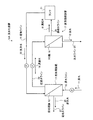
図1は、実施例1に係る淡水化装置を示す概念図である。
図1に示すように、本実施例に係る淡水化装置10Aは、原水(原水)11中の濁質分を濾過する前処理膜12を有する前処理装置13と、前記前処理装置13から供給された濾過水14から塩分を除去して淡水15を得る逆浸透膜(RO膜)16を有する逆浸透膜装置17と、前記逆浸透膜装置17からの塩分が濃縮された濃縮水18を前記前処理装置13に送給する逆洗ライン19とを具備してなり、前記濃縮水18を洗浄水20として用いて、前記前処理膜12の逆洗浄を行うようにしている。
ここで、図中、符号21は濃縮水18を貯留するタンクであり、22は原水11を前処理装置13に供給する原水ライン、23は濾過水14を前処理装置13から逆浸透膜装置17に供給する濾過水ライン、24は濃縮水18をタンク21に供給する濃縮水ライン、25は淡水15を外部の水使用設備等に供給する淡水ライン、Pは送給液ポンプを図示する。
A desalination apparatus according to a first embodiment of the present invention will be described with reference to the drawings.
FIG. 1 is a conceptual diagram illustrating a desalination apparatus according to a first embodiment.
As shown in FIG. 1, a
Here, in the figure,
前記構成の淡水化装置10Aにおいて、原水11は前処理装置13の前処理膜12で濁質分を除去して、濾過水ライン23を経由して濾過水14が逆浸透膜装置17に送給される。そして、逆浸透膜装置17で塩分を濃縮して淡水15を得た後、淡水ライン25を経由して外部の図示しない水使用設備等に送給される。なお、濃縮された濃縮水18は濃縮水ライン24を経由してタンク21に貯留される。ここで、濁質分を除去する前記前処理膜12は、例えばUF膜(限外濾過膜)又はMF膜(精密濾過膜)等の分離膜を挙げることができるがこれらに限定されるものではない。
In the
そして、前処理装置13を逆洗浄する場合には、所定時間の淡水化を行った後、原水11の供給を停止し、タンク21から濃縮水18を洗浄水20として逆洗ライン19を経由して前処理装置13に送給し、前処理膜12の逆洗を行う。そして濁質分を含む逆洗水26は逆洗水ライン27から外部に送給され、所定の処理を行う。
When the
この結果、従来技術においては濾過水14の一部を洗浄水として用いていたので、前処理装置13からの濾過水14の回収率が低下していたが、本実施例によれば濾過水14の減少が皆無となり、濾過水14の全量を逆浸透膜装置17に供給して淡水15に変換することができ、淡水化処理における経済性が向上する。
As a result, in the prior art, since a part of the filtered
また、本発明における洗浄水20は、従来の逆洗水とは異なり、逆浸透膜装置17から排出される濃縮水18を用いるようにしているので、塩分濃度が高く(塩分濃度は原水の1.5〜2倍)、通常の海洋細菌が死滅することなる。よって、前処理膜12の逆洗浄処理において、濁質の除去と共に、殺菌処理を行うことができるという、相乗効果を奏することとなる。
Further, unlike the conventional backwash water, the
次に、本発明による実施例2に係る淡水化装置について、図面を参照して説明する。
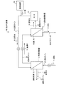
図2は、実施例2に係る淡水化装置を示す概念図である。なお、図1の淡水化装置と同一の部材については、同一の符号を付してその説明は省略する。
図2に示すように、本実施例に係る淡水化装置10Bは、実施例1の淡水化装置10Aにおいて、逆洗ライン19に酸31を供給する酸供給部32を設けてなるものである。
Next, a desalination apparatus according to Embodiment 2 of the present invention will be described with reference to the drawings.
FIG. 2 is a conceptual diagram illustrating a desalination apparatus according to a second embodiment. In addition, about the member same as the desalination apparatus of FIG. 1, the same code | symbol is attached | subjected and the description is abbreviate | omitted.
As shown in FIG. 2, the
これにより、酸31を供給して洗浄水20を中和するようにしているので、塩濃度が高い(塩分濃度は1.5〜2倍)濃縮水18を用いた場合においても、逆洗ライン19内の配管内部のスケール付着を防止することができる。
なお、供給する酸31は、塩酸、硫酸、硝酸等の希薄な酸を供給して、pHが6となるようにしている。
As a result, the acid 31 is supplied to neutralize the
The acid 31 to be supplied is supplied with a dilute acid such as hydrochloric acid, sulfuric acid or nitric acid so that the pH becomes 6.
次に、本発明による実施例3に係る淡水化装置について、図面を参照して説明する。
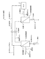
図3は、実施例3に係る淡水化装置を示す概念図である。なお、図1の淡水化装置と同一の部材については、同一の符号を付してその説明は省略する。
図3に示すように、本実施例に係る淡水化装置10Cは、実施例1の淡水化装置10Aにおいて、逆洗ライン19にフラッシング部であるフラッシングライン33を設けたものである。
Next, a desalination apparatus according to Embodiment 3 of the present invention will be described with reference to the drawings.
FIG. 3 is a conceptual diagram illustrating a desalination apparatus according to a third embodiment. In addition, about the member same as the desalination apparatus of FIG. 1, the same code | symbol is attached | subjected and the description is abbreviate | omitted.
As shown in FIG. 3, the
これにより、フラッシングライン33によりフラッシングさせて濃縮水18を放出するようにしておくことにより、逆洗しない間における逆洗ライン19の配管内部での微生物の繁殖を抑制するようにしている。
Thus, by flushing with the flushing line 33 and releasing the
次に、本発明による実施例4に係る淡水化装置について、図面を参照して説明する。
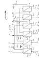
図4は、実施例4に係る淡水化装置を示す概念図である。なお、図1の淡水化装置と同一の部材については、同一の符号を付してその説明は省略する。
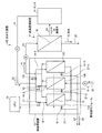
図4に示すように、本実施例に係る淡水化装置10Dは、実施例1の淡水化装置10Aに係る前処理装置13と逆浸透膜装置17とを各複数台(本実施例では3台)設置したものである。
Next, a desalination apparatus according to Embodiment 4 of the present invention will be described with reference to the drawings.
FIG. 4 is a conceptual diagram illustrating a desalination apparatus according to a fourth embodiment. In addition, about the member same as the desalination apparatus of FIG. 1, the same code | symbol is attached | subjected and the description is abbreviate | omitted.
As shown in FIG. 4, the desalination apparatus 10D according to the present embodiment includes a plurality of
すなわち、本実施例に係る淡水化装置10Dは、原水11中の濁質分を濾過する前処理膜12を有する前処理装置13−1〜13−3と、前記前処理装置13−1〜13−3からの濾過水14から塩分を除去して淡水15を得る逆浸透膜16を有する逆浸透膜装置17−1〜17−3と、前記逆浸透膜装置17−1〜17−3からの塩分が濃縮された濃縮水18を前記前処理装置13−1〜13−3に送給する逆洗ライン19−1〜19−3とを具備してなり、濃縮水18を洗浄水20として用いて、前記前処理膜12の逆洗浄を行うようにしている。
ここで、本実施例では、逆洗ライン19−1〜19−3にそれぞれ洗浄水20を供給するために、開閉弁V1〜V3が介装され、この開閉弁V1〜V3の開閉により、洗浄を行うようにしている。
That is, the desalination apparatus 10D which concerns on a present Example is the pretreatment apparatus 13-1 to 13-3 which has the pretreatment film |
Here, in this embodiment, on-off valves V1 to V3 are provided to supply the
本実施例では前処理装置と逆浸透膜装置とを複数台を用いているので、いずれかの装置を停止して逆洗浄する際にも、濃縮水18を確保することができるので、実施例1のようにタンク21を設置することがなくなる。
In this embodiment, since a plurality of pretreatment devices and reverse osmosis membrane devices are used, the
図4に示す実施例の場合では、前処理装置13−1、13−3では濾過を行っており、逆浸透膜装置17−1、17−3から淡水15を得ているので、バルブV1とV3とを閉じている。そして、前処理装置13−2に対しては、原水11の供給を停止し、前記逆浸透膜装置17−1、17−3からの濃縮水18を用いて、バルブV2を開放させることにより前処理装置13−2内に供給することで、前記前処理装置13−2の前処理膜12の逆洗浄を行うようにしている。
In the case of the embodiment shown in FIG. 4, the pretreatment devices 13-1 and 13-3 perform filtration, and
これにより、所定時間原水11を濾過した前処理膜12を交互に洗浄水20で洗浄するができる。例えば1時間運転した後に5分程度の逆洗浄を行い、常に効率的な淡水化を行うようにすることができる。
Thereby, the pretreatment film |
なお、本実施例では、前処理装置と逆浸透膜装置との設置台数は同数としたが、本発明はこれに限定されるものではなく、いずれか一方が少ない場合でも適用することができる。 In this embodiment, the number of pretreatment devices and reverse osmosis membrane devices installed is the same. However, the present invention is not limited to this, and the present invention can be applied even when one of them is small.
次に、本発明による実施例5に係る淡水化装置について、図面を参照して説明する。
図5は、実施例5に係る淡水化装置を示す概念図である。なお、図1乃至4に係る淡水化装置と同一の部材については、同一の符号を付してその説明は省略する。
図5に示すように、本実施例に係る淡水化装置10Eは、実施例1の淡水化装置10Aに係る前処理装置13を複数の前処理モジュール13A〜13Cから構成してなり、これらのモジュールで濾過された濾過水14を1台の逆浸透膜装置17で淡水化を行うようにしたものである。
Next, a desalination apparatus according to Embodiment 5 of the present invention will be described with reference to the drawings.
FIG. 5 is a conceptual diagram illustrating a desalination apparatus according to a fifth embodiment. In addition, about the same member as the desalination apparatus which concerns on FIG. 1 thru | or 4, the same code | symbol is attached | subjected and the description is abbreviate | omitted.
As shown in FIG. 5, the desalination apparatus 10E according to the present embodiment is configured by configuring the
また、逆洗水26の排出ライン27−1〜27−3に濁質計51−1〜51−3を各々設置し、これらの濁質計からの情報を制御装置(CPU)52に送るようにしている。そして、この情報により、前処理膜12への洗浄水20の供給量を、バルブV1〜V3の開閉時間を調整することで、その洗浄度合いを調節するようにしている。
Moreover, the turbidimeters 51-1 to 51-3 are respectively installed in the discharge lines 27-1 to 27-3 of the
本実施例では、濃縮水18を洗浄水20として用いているので、前処理膜12の洗浄が十分でない場合には、前記濁質計51−1〜51−3の情報を元にして十分な洗浄を行うことができる。すなわち、従来では、濁質計を設置している場合でも、濾過水を洗浄水として用いていたので、淡水化量が減少するので、十分な洗浄を実施することができなかったが、本発明によれば、濃縮水は多量に発生するので、所望の洗浄基準に満たない場合には、更に濃縮水を用いての洗浄が可能となる。
In the present embodiment, the
以上のように、本発明に係る淡水化装置は、従来のような濾過水の一部を用いて前処理膜の洗浄を行うことがないので、淡水化効率を低下させることがないので、海水を淡水化する設備に用いて適している。 As described above, since the desalination apparatus according to the present invention does not clean the pretreatment membrane using a part of the conventional filtered water, the desalination efficiency is not lowered. It is suitable for use in facilities that desalinate water.
10A〜10E 淡水化装置
11 原水
12 前処理膜
13 前処理装置
14 濾過水
15 淡水
16 逆浸透膜
17 逆浸透膜装置
18 濃縮水
19 逆洗ライン
20 洗浄水
21 タンク
10A to
Claims (8)
前記前処理装置からの濾過水から塩分を除去して淡水を得る逆浸透膜を有する逆浸透膜装置と、
前記逆浸透膜装置からの塩分が濃縮された濃縮水を前記前処理装置に送給する逆洗ラインとを具備してなり、前記濃縮水を前記前処理膜の逆洗浄に用いてなることを特徴とする淡水化装置。 A pretreatment device having a pretreatment membrane for filtering turbid components in raw water;
A reverse osmosis membrane device having a reverse osmosis membrane that obtains fresh water by removing salt from the filtered water from the pretreatment device;
A backwash line for feeding the concentrated water from which the salt content from the reverse osmosis membrane device is concentrated to the pretreatment device, and using the concentrated water for backwashing the pretreatment membrane. Features a desalination device.
前記前処理装置又は逆浸透膜装置のいずれか一方又は両方を複数台具備することを特徴とする淡水化装置。 In claim 1,
A desalination apparatus comprising a plurality of either or both of the pretreatment apparatus and the reverse osmosis membrane apparatus.
前記逆浸透膜装置からの塩分が濃縮された濃縮水を貯留する貯留タンクを具備することを特徴とする淡水化装置。 In claim 1 or 2,
A desalination apparatus comprising a storage tank for storing concentrated water enriched in salt from the reverse osmosis membrane apparatus.
前記逆洗ラインに酸を供給する酸供給部を具備することを特徴とする淡水化装置。 In any one of Claims 1 thru | or 3,
The desalination apparatus characterized by including the acid supply part which supplies an acid to the said backwash line.
前記逆洗ラインがフラッシング部を具備することを特徴とする淡水化装置。 In any one of Claims 1 thru | or 4,
The desalination apparatus, wherein the backwash line includes a flushing section.
前記前処理装置から排出される逆洗水の排出ラインに濁度計を具備してなり、濁度に応じて濃縮水の供給量を調整してなることを特徴とする淡水化装置。 In any one of Claims 1 thru | or 5,
A desalination apparatus comprising a turbidimeter in a discharge line of backwash water discharged from the pretreatment apparatus, and adjusting a supply amount of concentrated water according to the turbidity.
前記前処理膜の逆洗浄後の逆洗浄液中の濁度を計測しつつ、逆洗浄に用いる濃縮水の供給量を調整することを特徴とする淡水化装置の前処理膜の洗浄方法。 In claim 7,
A method for cleaning a pretreatment membrane of a desalination apparatus, comprising adjusting a supply amount of concentrated water used for backwashing while measuring turbidity in a backwashing liquid after backwashing the pretreatment membrane.
Priority Applications (1)
| Application Number | Priority Date | Filing Date | Title |
|---|---|---|---|
| JP2005200459A JP2007014902A (en) | 2005-07-08 | 2005-07-08 | Desalination apparatus and washing method of pretreatment membrane of desalination apparatus |
Applications Claiming Priority (1)
| Application Number | Priority Date | Filing Date | Title |
|---|---|---|---|
| JP2005200459A JP2007014902A (en) | 2005-07-08 | 2005-07-08 | Desalination apparatus and washing method of pretreatment membrane of desalination apparatus |
Publications (1)
| Publication Number | Publication Date |
|---|---|
| JP2007014902A true JP2007014902A (en) | 2007-01-25 |
Family
ID=37752507
Family Applications (1)
| Application Number | Title | Priority Date | Filing Date |
|---|---|---|---|
| JP2005200459A Pending JP2007014902A (en) | 2005-07-08 | 2005-07-08 | Desalination apparatus and washing method of pretreatment membrane of desalination apparatus |
Country Status (1)
| Country | Link |
|---|---|
| JP (1) | JP2007014902A (en) |
Cited By (6)
| Publication number | Priority date | Publication date | Assignee | Title |
|---|---|---|---|---|
| KR100800453B1 (en) * | 2007-01-31 | 2008-02-04 | 주식회사 클로랜드 | Water treatment apparatus using the hollow fiber membrane module |
| JP2011177654A (en) * | 2010-03-01 | 2011-09-15 | Asahi Kasei Chemicals Corp | Filtration apparatus |
| JP2011212541A (en) * | 2010-03-31 | 2011-10-27 | Kurita Water Ind Ltd | Filtration device and water treatment device |
| JP2011212542A (en) * | 2010-03-31 | 2011-10-27 | Kurita Water Ind Ltd | Method for backwashing filter treatment means and water treatment apparatus therefor |
| JP2021037482A (en) * | 2019-09-04 | 2021-03-11 | オルガノ株式会社 | Water treatment system and water treatment method |
| WO2024070576A1 (en) * | 2022-09-26 | 2024-04-04 | 東レ株式会社 | Fresh water production method |
Citations (3)
| Publication number | Priority date | Publication date | Assignee | Title |
|---|---|---|---|---|
| JPH09220449A (en) * | 1996-02-15 | 1997-08-26 | Kurita Water Ind Ltd | Membrane separation device |
| JPH10263539A (en) * | 1997-03-28 | 1998-10-06 | Japan Organo Co Ltd | Member treating method of water to be treated and membrane treating device |
| JPH11244852A (en) * | 1998-02-26 | 1999-09-14 | Japan Organo Co Ltd | Desalination device and back washing method of filter used for desalination device |
-
2005
- 2005-07-08 JP JP2005200459A patent/JP2007014902A/en active Pending
Patent Citations (3)
| Publication number | Priority date | Publication date | Assignee | Title |
|---|---|---|---|---|
| JPH09220449A (en) * | 1996-02-15 | 1997-08-26 | Kurita Water Ind Ltd | Membrane separation device |
| JPH10263539A (en) * | 1997-03-28 | 1998-10-06 | Japan Organo Co Ltd | Member treating method of water to be treated and membrane treating device |
| JPH11244852A (en) * | 1998-02-26 | 1999-09-14 | Japan Organo Co Ltd | Desalination device and back washing method of filter used for desalination device |
Cited By (9)
| Publication number | Priority date | Publication date | Assignee | Title |
|---|---|---|---|---|
| KR100800453B1 (en) * | 2007-01-31 | 2008-02-04 | 주식회사 클로랜드 | Water treatment apparatus using the hollow fiber membrane module |
| JP2011177654A (en) * | 2010-03-01 | 2011-09-15 | Asahi Kasei Chemicals Corp | Filtration apparatus |
| JP2011212541A (en) * | 2010-03-31 | 2011-10-27 | Kurita Water Ind Ltd | Filtration device and water treatment device |
| JP2011212542A (en) * | 2010-03-31 | 2011-10-27 | Kurita Water Ind Ltd | Method for backwashing filter treatment means and water treatment apparatus therefor |
| JP2021037482A (en) * | 2019-09-04 | 2021-03-11 | オルガノ株式会社 | Water treatment system and water treatment method |
| WO2021044785A1 (en) * | 2019-09-04 | 2021-03-11 | オルガノ株式会社 | Water treatment system and water treatment method |
| CN113396130A (en) * | 2019-09-04 | 2021-09-14 | 奥加诺株式会社 | Water treatment system and water treatment method |
| JP7239428B2 (en) | 2019-09-04 | 2023-03-14 | オルガノ株式会社 | Water treatment system and water treatment method |
| WO2024070576A1 (en) * | 2022-09-26 | 2024-04-04 | 東レ株式会社 | Fresh water production method |
Similar Documents
| Publication | Publication Date | Title |
|---|---|---|
| JP5582740B2 (en) | Desalination apparatus and method for cleaning pretreatment membrane of desalination apparatus | |
| JP2007130523A (en) | Membrane washing method for water treatment system | |
| Chew et al. | Practical performance analysis of an industrial-scale ultrafiltration membrane water treatment plant | |
| KR101928212B1 (en) | Method for washing reverse osmosis membrane | |
| JP2007014902A (en) | Desalination apparatus and washing method of pretreatment membrane of desalination apparatus | |
| JP2010094584A (en) | Method of treating ballast water and apparatus for treating ballast water | |
| JP2015229146A (en) | Cleaning method of membrane module | |
| JPH10225682A (en) | Method of removing boron in reverse osmosis seawater desalination | |
| JP4804176B2 (en) | Seawater filtration | |
| WO2010096047A2 (en) | Filter cleaning method | |
| JP6344114B2 (en) | Water treatment apparatus and water treatment equipment cleaning method | |
| JP2007216102A (en) | Filtering device, and membrane washing method of this filtering device | |
| JP5339054B2 (en) | Water treatment method | |
| JP2007268359A (en) | Membrane separation method | |
| JP2011104504A (en) | Washing method of water treatment facility | |
| JP5250684B2 (en) | Seawater desalination method and seawater desalination apparatus | |
| JP2011041907A (en) | Water treatment system | |
| WO2012057176A1 (en) | Water-treatment method and desalinization method | |
| JP2013034938A (en) | Method for washing membrane module | |
| JP6428017B2 (en) | Water treatment apparatus and water treatment equipment cleaning method | |
| JP6467911B2 (en) | Water treatment system | |
| JP2017176951A (en) | Method for cleaning separation membrane module | |
| JP2001252536A (en) | Method for cleaning filter membrane and apparatus for filtering seawater using the same | |
| Xie et al. | Pre-treatment optimisation of SWRO membrane desalination under tropical conditions | |
| EP2218494B1 (en) | Method and device for the purification of an aqueous fluid |
Legal Events
| Date | Code | Title | Description |
|---|---|---|---|
| A621 | Written request for application examination |
Free format text: JAPANESE INTERMEDIATE CODE: A621 Effective date: 20070703 |
|
| A977 | Report on retrieval |
Free format text: JAPANESE INTERMEDIATE CODE: A971007 Effective date: 20090716 |
|
| A131 | Notification of reasons for refusal |
Free format text: JAPANESE INTERMEDIATE CODE: A131 Effective date: 20090901 |
|
| A521 | Written amendment |
Free format text: JAPANESE INTERMEDIATE CODE: A523 Effective date: 20091030 |
|
| A02 | Decision of refusal |
Free format text: JAPANESE INTERMEDIATE CODE: A02 Effective date: 20100406 |