JP2006312936A - Controlled leakage valve for piston cooling nozzle - Google Patents
Controlled leakage valve for piston cooling nozzle Download PDFInfo
- Publication number
- JP2006312936A JP2006312936A JP2006123845A JP2006123845A JP2006312936A JP 2006312936 A JP2006312936 A JP 2006312936A JP 2006123845 A JP2006123845 A JP 2006123845A JP 2006123845 A JP2006123845 A JP 2006123845A JP 2006312936 A JP2006312936 A JP 2006312936A
- Authority
- JP
- Japan
- Prior art keywords
- valve
- cooling
- piston
- channel
- pressure
- Prior art date
- Legal status (The legal status is an assumption and is not a legal conclusion. Google has not performed a legal analysis and makes no representation as to the accuracy of the status listed.)
- Pending
Links
Images


Classifications
-
- F—MECHANICAL ENGINEERING; LIGHTING; HEATING; WEAPONS; BLASTING
- F01—MACHINES OR ENGINES IN GENERAL; ENGINE PLANTS IN GENERAL; STEAM ENGINES
- F01P—COOLING OF MACHINES OR ENGINES IN GENERAL; COOLING OF INTERNAL-COMBUSTION ENGINES
- F01P3/00—Liquid cooling
- F01P3/06—Arrangements for cooling pistons
- F01P3/08—Cooling of piston exterior only, e.g. by jets
-
- F—MECHANICAL ENGINEERING; LIGHTING; HEATING; WEAPONS; BLASTING
- F01—MACHINES OR ENGINES IN GENERAL; ENGINE PLANTS IN GENERAL; STEAM ENGINES
- F01M—LUBRICATING OF MACHINES OR ENGINES IN GENERAL; LUBRICATING INTERNAL COMBUSTION ENGINES; CRANKCASE VENTILATING
- F01M1/00—Pressure lubrication
- F01M1/08—Lubricating systems characterised by the provision therein of lubricant jetting means
-
- F—MECHANICAL ENGINEERING; LIGHTING; HEATING; WEAPONS; BLASTING
- F01—MACHINES OR ENGINES IN GENERAL; ENGINE PLANTS IN GENERAL; STEAM ENGINES
- F01M—LUBRICATING OF MACHINES OR ENGINES IN GENERAL; LUBRICATING INTERNAL COMBUSTION ENGINES; CRANKCASE VENTILATING
- F01M1/00—Pressure lubrication
- F01M1/16—Controlling lubricant pressure or quantity
Abstract
Description
本発明は、内燃エンジンにおけるピストンの冷却ノズル用の供給装置であって、ピストンの頂面、即ち、燃焼室の外側のピストンの表面に対して、又は、ピストンの頂面のギャラリー内に油といった冷却流体を発射可能にする供給装置に係る。 The invention is a supply device for a cooling nozzle of a piston in an internal combustion engine, such as oil on the top surface of the piston, i.e. on the surface of the piston outside the combustion chamber or in the gallery on the top surface of the piston. The present invention relates to a supply device that enables discharge of a cooling fluid.
習慣的に使用されているピストン冷却ノズルは、エンジン内に固定され、冷却流体用の流入開口と連通する取り外し可能な部品である。ノズルの位置は、冷却流体の噴流がピストン頂面の又はピストン頂面のギャラリーの正確なゾーンに向けて方向付けられるような精度で決定される。ノズルは交換可能な部品であって、その差し替えは、原則的に、エンジンブロック自体のオーバーホールを必要としない。 A customarily used piston cooling nozzle is a removable part that is fixed in the engine and communicates with an inlet opening for cooling fluid. The position of the nozzle is determined with accuracy such that the jet of cooling fluid is directed towards the exact zone of the piston top surface or the gallery of the piston top surface. The nozzle is a replaceable part, and its replacement in principle does not require an overhaul of the engine block itself.
今日のエンジンでは、ピストンの冷却ノズルは、エンジンの潤滑回路によって供給される。その回路内を、冷却及び潤滑流体が、エンジン自体によって回転駆動される油ポンプによって推進される。 In today's engines, the piston cooling nozzle is supplied by the engine's lubrication circuit. Within that circuit, cooling and lubricating fluid is propelled by an oil pump that is driven in rotation by the engine itself.
従って、冷却流体は、2つの役割を有する。第1の役割は、エンジン、特に、ピストンの加熱した素子を冷却し、それらの素子が発生する熱エネルギーを、冷却流体を介して運び去ることである。冷却流体の流速及び熱容量は良好に選択される。冷却流体の第2の役割は、クランク軸受、連接棒の大小の端、ピストンとライナーの間の摺動面といったエンジンの動く部品の潤滑を確実にすることである。使用される流体は一般的に油である。従って、本願では、油、冷却流体、又は更には冷却及び潤滑流体を区別することなく使用する。 Accordingly, the cooling fluid has two roles. The first role is to cool the heated elements of the engine, in particular the piston, and carry away the thermal energy generated by those elements via the cooling fluid. The flow rate and heat capacity of the cooling fluid are well selected. The second role of the cooling fluid is to ensure lubrication of moving parts of the engine such as crank bearings, connecting rod large and small ends, sliding surfaces between the piston and liner. The fluid used is generally oil. Accordingly, in this application, oil, cooling fluid, or even cooling and lubricating fluid are used without distinction.
競争力があるように機器の費用を下げる絶え間ない努力において、自動車設計者は、油ポンプのサイズを減少することを試みる。この油ポンプの小規模化によって、エンジン設計者に、低いエンジン回転数において、潤滑のための油の低い流速で対処しなくてはならなくなる。従って、小型の油ポンプに適応し、同時に依然として、油の容認された低い流速においても低回転数のエンジンの動く部分の良好な潤滑を確実にすることが可能な手段を設計することが必要である。 In constant efforts to reduce equipment costs to be competitive, automotive designers attempt to reduce the size of the oil pump. This downsizing of the oil pump requires engine designers to deal with low oil flow rates for lubrication at low engine speeds. It is therefore necessary to design a means that can accommodate small oil pumps and at the same time still ensure good lubrication of the moving parts of the engine at low speeds even at the low oil flow rates allowed. is there.
このために、冷却流体の圧力が特定の閾値を超えるまで冷却流体の循環を、バルブによって阻止可能な冷却ノズル用の一般的な供給装置がある。冷却ノズル用の供給装置のそのような構造のバルブは、時に、冷却流体の通過のための開口を遮断するよう座部に対して圧縮バネによって押される球の形である。 For this purpose, there are common supply devices for cooling nozzles that can prevent the circulation of the cooling fluid by means of valves until the pressure of the cooling fluid exceeds a certain threshold. Such structured valves of the supply device for the cooling nozzle are sometimes in the form of a sphere that is pressed by a compression spring against the seat to block the opening for the passage of cooling fluid.
エンジンが、低回転数で回転する際、冷却流体の圧力は、特定の閾値圧力未満である。即ち、座部の開口は遮断されるので、ピストン頂面のゾーンに向けて方向付けられる冷却流体の噴流はない。このようにすると、低エンジン回転数において、油の大部分は、クランク軸受、連接棒の大端、更には小端といったエンジンのより敏感な動く部品の潤滑のために取っておかれる。 As the engine rotates at low rpm, the pressure of the cooling fluid is below a certain threshold pressure. That is, because the seat opening is blocked, there is no jet of cooling fluid directed toward the zone of the piston top surface. In this way, at low engine speeds, most of the oil is set aside to lubricate more sensitive moving parts of the engine, such as crank bearings, connecting rod large ends, and even small ends.
高エンジン回転数では、冷却流体の圧力は、特定の閾値圧力より大きく、そして、冷却ノズルの油供給装置のバルブは開かれ、ピストン頂面のゾーンに対して冷却流体の噴流が方向付けられることを可能にする。 At high engine speeds, the cooling fluid pressure is greater than a certain threshold pressure, and the cooling nozzle oil supply valve is opened and the jet of cooling fluid is directed against the zone at the top of the piston. Enable.
本発明は、そのようなバルブ型供給装置を用いた際のエンジンの内部の動く部品への摩耗影響の観察の結果生まれたものである。 The present invention was born as a result of observing the influence of wear on moving parts inside the engine when such a valve-type supply device is used.
同様に、周知のバルブ型冷却ノズルでは、人間の耳が知覚可能な雑音及び振動が、冷却ノズル用の供給装置のバルブを開くときに生成され、これは、ユーザにとって寄生的雑音源となる。 Similarly, in known valve-type cooling nozzles, noise and vibration perceptible to the human ear are generated when opening the valve of the supply device for the cooling nozzle, which is a source of parasitic noise for the user.
低エンジン回転数での潤滑を向上するために、2つの回路を有する油流入装置が既に、特許文献1に提案されている。この文献では、油は、エンジンブロック内で主チャンネルと二次チャンネルとに分かれる、エンジンブロック内に形成された共通チャネルからエンジン気筒内に入れられる。バルブ型ノズルは、エンジンブロックの主チャンネルの端において接続され、上流セグメントと、制御バルブと、主油噴流をピストン頂面に向けて長手方向に案内する下流セグメントを含む。エンジンブロックの二次チャネルは、エンジンブロック内の油を、バルブの上流にある共通チャンネルからエンジン気筒内に直接的に運び、二次油噴流をエンジン気筒において横断するよう案内する。主油噴流と二次油噴流は交差する。横断するよう案内される二次油噴流は、気筒におけるピストンの移動に対して垂直であり、従って、ピストンの移動によって不安定にされる。その結果、その効率は最適ではない。二次チャンネルの形成は、エンジンブロックの更なる機械加工を必要とし、この機械加工は費用がかかりまた変更可能ではなく或いは全ての現行のエンジンブロック構成に容易に適応可能ではない。
本発明は、摩耗影響を低減することを可能にし、同時に、バルブ型供給装置が取り付けられたエンジンにおける寄生的雑音及び振動を低減する取り外し可能及び交換可能な手段を、エンジンブロックの変更及び改変なく、設計することを目的とする。 The present invention makes it possible to reduce wear effects while at the same time providing removable and replaceable means for reducing parasitic noise and vibration in engines fitted with valve-type feeders, without engine block changes and modifications. The purpose is to design.
これらの目的及び他の目的を達成するために、本発明は、内燃エンジンの1つ以上のピストンに冷却及び潤滑流体を供給する装置において、該装置は、内燃エンジンのピストン用の1つ以上の取り外し可能な冷却及び潤滑ノズルを含み、該装置は、少なくとも1つの取り外し可能なバルブを有し、バルブは、供給チャネルに接続可能な上流チャネルと、冷却流体をピストンに運ぶ下流チャネルを有し、取り外し可能なバルブは、座部の開口を遮断するようコンパートメント内を可動な遮断素子を含む閉鎖手段を有し、取り外し可能なバルブは、上流の圧力が閾値圧力より大きい場合には開き、上流の圧力が閾値圧力未満である場合には閉じることによって冷却流体の圧力に反応する装置を提供し、本発明では、取り外し可能なバルブは更に、バルブの閉鎖手段と並列して、上流チャネルを下流チャネルに接続する較正された漏出の手段を有する。 To achieve these and other objects, the present invention provides an apparatus for supplying cooling and lubricating fluid to one or more pistons of an internal combustion engine, the apparatus comprising one or more for an internal combustion engine piston. Including a removable cooling and lubrication nozzle, the apparatus having at least one removable valve, the valve having an upstream channel connectable to a supply channel and a downstream channel carrying cooling fluid to the piston; The removable valve has closing means including a blocking element movable within the compartment to block the seat opening, and the removable valve opens when the upstream pressure is greater than the threshold pressure, and the upstream valve A device is provided that reacts to the pressure of the cooling fluid by closing when the pressure is below a threshold pressure, and in the present invention, the removable valve further comprises: In parallel with the closure means Lube comprises means calibrated leak to connect upstream channel to the downstream channel.
このような構造は、エンジンが低回転数で回転しているときにも冷却ノズル内に低流速の流体を供給し、それにより、ピストンとライナーの間の摺動接触に潤滑油を差すことが依然として可能である。漏れ量は、低エンジン回転数における油流速は、摺動接触の潤滑を可能にするのにちょうど十分であり、有意にエンジンの他の動く部品の潤滑を低減しないよう較正される。 Such a structure provides a low flow rate fluid into the cooling nozzle even when the engine is rotating at a low speed, thereby injecting lubricating oil into the sliding contact between the piston and the liner. Still possible. The amount of leakage is calibrated so that the oil flow rate at low engine speeds is just enough to allow lubrication of sliding contacts and does not significantly reduce lubrication of other moving parts of the engine.
高エンジン回転数では、摺動接触にあるピストンとライナーを冷却することが一般的に必要となる。エンジン回転数における増加は、冷却回路における流体の圧力を増加する。その結果、可動な遮断素子は、座部から離れるよう動き、それにより、油が、座部に形成された開口を通過することを可能にする。その結果、エンジンの動く部品の潤滑と、熱エネルギーを運び去ることによるそれらの冷却の両方を確実にする十分な油流速を有する。 At high engine speeds it is generally necessary to cool the piston and liner in sliding contact. An increase in engine speed increases the fluid pressure in the cooling circuit. As a result, the movable blocking element moves away from the seat, thereby allowing oil to pass through the opening formed in the seat. As a result, it has a sufficient oil flow rate to ensure both lubrication of the moving parts of the engine and their cooling by carrying away heat energy.
このようにすると、エンジンが低回転数で回転する、即ち、冷却流体の圧力が特定の閾値圧力未満である場合を含むエンジンの動く部品の永久且つ良好に分布された潤滑を確実にすることによって摩耗の影響を最小限にする。噴流の方向は変わらず、また、バルブの状態に関係なくピストン頂面に対して長手方向のままである。従って、もたらされる潤滑は最適である。何故なら、潤滑は、ピストンの動作によって妨げられないからである。 In this way, by ensuring permanent and well-distributed lubrication of the moving parts of the engine, including when the engine rotates at a low speed, i.e. when the cooling fluid pressure is below a certain threshold pressure. Minimize wear effects. The direction of the jet remains unchanged and remains longitudinal with respect to the piston top surface regardless of the state of the valve. The resulting lubrication is therefore optimal. This is because lubrication is not hindered by piston movement.
低エンジン回転数において、冷却流体の低流速が、ピストン頂面のゾーンを指すノズルを冷却するのに十分である。これは十分である。何故なら、低エンジン回転数において、冷却流体が潤滑の役割以外の役割を果たす必要がないからである。 At low engine speeds, the low flow rate of the cooling fluid is sufficient to cool the nozzle pointing to the piston top zone. This is enough. This is because at low engine speeds, the cooling fluid need not play any role other than lubrication.
同時に、冷却流体の圧力が特定の閾値圧力未満である場合に下流チャネル内に僅かな油循環を維持することは、供給装置のバルブの開放時の上流チャネルにおける圧力と下流チャネルにおける圧力との差を低減することが可能である。その結果、供給装置のバルブの遮断素子の動作を減衰し、それにより、バルブの遮断素子の移動によって生成される雑音を顕著に低減する。 At the same time, maintaining a slight oil circulation in the downstream channel when the cooling fluid pressure is below a certain threshold pressure is the difference between the pressure in the upstream channel and the pressure in the downstream channel when the supply valve is opened. Can be reduced. As a result, the operation of the shut-off element of the valve of the supply device is attenuated, thereby significantly reducing the noise generated by the movement of the shut-off element of the valve.
第1の実施例では、冷却流体供給装置は、ピストンの頂面用の幾つかの冷却及び潤滑ノズルに共通の較正された漏出の手段を有するバルブを含むことが可能である。 In a first embodiment, the cooling fluid supply can include a valve having calibrated leakage means common to several cooling and lubrication nozzles for the top surface of the piston.
第2の実施例では、冷却流体供給装置は、ピストンの頂面の各冷却及び潤滑ノズルは、較正された漏出の手段を有するバルブを含むよう構成されることが可能である。 In a second embodiment, the cooling fluid supply device can be configured such that each cooling and lubrication nozzle on the top surface of the piston includes a valve having calibrated leakage means.
有利には、閾値圧力は、ガソリンエンジンについては、約1.8乃至約2.8バールであり、ディーゼルエンジンについては、約1.2乃至約2.5バールである。 Advantageously, the threshold pressure is about 1.8 to about 2.8 bar for gasoline engines and about 1.2 to about 2.5 bar for diesel engines.
好適には、較正された漏出の手段は、バルブの座部に形成された少なくとも1つのノッチを含むことが可能である。 Suitably, the calibrated leakage means may comprise at least one notch formed in the seat of the valve.
従って、漏出手段を、経済的、単純、且つ高速な方法で実現することができ、この漏出手段は、形成されたノッチの深度によって容易に寸法調整可能である。 Thus, the leaking means can be realized in an economical, simple and fast way, and this leaking means can be easily dimensioned according to the depth of the notch formed.
本発明の構成された漏出の手段の第2の実施例は、以下のように考えられる。即ち、
−バルブは、コンパートメントの周りに配置され、下流チャネルと連通する環状室を有するバルブ本体を含み、
−遮断素子は、座部の開口と、環状室と連通するようコンパートメントに設けられた少なくとも1つのラジアル通路とを同時に遮断するピストンであり、
−較正された漏出の手段は、コンパートメントを環状室と永久連通させるラジアル孔であり、
−少なくとも1つのラジアル通路は、ラジアル孔の直径より大きい直径を有する。
The second embodiment of the constructed leakage means of the present invention is considered as follows. That is,
The valve comprises a valve body arranged around the compartment and having an annular chamber in communication with the downstream channel;
The blocking element is a piston that simultaneously blocks the opening of the seat and at least one radial passage provided in the compartment to communicate with the annular chamber;
The calibrated means of leakage is a radial hole that makes the compartment in permanent communication with the annular chamber;
The at least one radial passage has a diameter larger than the diameter of the radial hole;
本発明の装置の別の実施例は、以下のように考えられる。即ち、
−較正された漏出の手段は、バルブの座部に形成された少なくとも1つのノッチを含み、
−遮断素子は、ヘッドを有するピストンであり、
−ピストンのヘッドは、コンパートメントを下流チャネルと連通させる軸方向通路と連通する横通路を有する。
Another embodiment of the device of the present invention is considered as follows. That is,
The calibrated leakage means comprises at least one notch formed in the seat of the valve;
The blocking element is a piston having a head;
The head of the piston has a transverse passage communicating with an axial passage communicating the compartment with the downstream channel;
本発明では、内燃エンジンは、上述したような装置によって冷却及び循環流体が供給される1つ以上のピストンを有しうる。 In the present invention, the internal combustion engine may have one or more pistons that are supplied with cooling and circulating fluids by a device as described above.
有利には、本発明のバルブ型供給装置は、以下を場合により含むバルブノズルを形成するようノズル内に全体的に組み込まれることが可能である。即ち、
−上流チャネル及び下流チャネルを有するバルブ本体と、
−上流チャネルと下流チャネルとの間の座部の開口を遮断するようコンパートメント内を可動な遮断素子を含む、バルブ本体内における閉鎖手段と、
−閉鎖手段と並列して上流チャネルを下流チャネルに接続する較正された漏出の手段とを含み、遮断素子は、上流の圧力が閾値圧力より大きい場合には開き、上流の圧力が閾値圧力未満である場合には閉じることによって冷却流体の圧力に反応する。
Advantageously, the valve-type supply device of the present invention can be integrated entirely within the nozzle to form a valve nozzle that optionally includes: That is,
A valve body having an upstream channel and a downstream channel;
A closing means in the valve body comprising a blocking element movable in the compartment to block the opening of the seat between the upstream channel and the downstream channel;
-A calibrated leakage means connecting the upstream channel to the downstream channel in parallel with the closing means, the blocking element being opened when the upstream pressure is greater than the threshold pressure, and the upstream pressure being less than the threshold pressure; In some cases, it reacts to the pressure of the cooling fluid by closing.
好適には、バルブ本体は、上流チャネルを有し、貫通の軸方向に沿ってエンジンのボア内に軸方向に適合し且つボアによって到着する冷却及び潤滑流体を受容するよう形作られる上流セグメントを含む。 Preferably, the valve body has an upstream channel and includes an upstream segment that is axially fitted into the engine bore along the axial direction of the penetration and is configured to receive cooling and lubricating fluid arriving by the bore. .
別の面では、バルブノズルは、バルブ本体における少なくとも1つの下流チャネルと、冷却及び潤滑流体の少なくとも1つの噴流を冷却されるべきピストン上に案内するための少なくとも1つの下流管を有する流出構造を含むことが可能である。 In another aspect, the valve nozzle comprises an outflow structure having at least one downstream channel in the valve body and at least one downstream tube for guiding at least one jet of cooling and lubricating fluid onto the piston to be cooled. It is possible to include.
有利には、冷却及び潤滑流体の下流流出管は、その自由端はピストンに向けられ、縮小部を含む湾曲管である。 Advantageously, the downstream outlet pipe for cooling and lubricating fluid is a curved pipe whose free end is directed to the piston and which includes a reduction.
本発明では、バルブノズルは、ガソリンエンジンについては、約1.8乃至約2.8バールであり、ディーゼルエンジンについては、約1.2乃至約2.5バールの閾値圧力を有することが可能である。 In the present invention, the valve nozzle can have a threshold pressure of about 1.8 to about 2.8 bar for gasoline engines and about 1.2 to about 2.5 bar for diesel engines. is there.
有利には、較正された漏出の手段は、バルブの座部に形成された少なくとも1つのノッチを含むことが可能である。 Advantageously, the calibrated leakage means may comprise at least one notch formed in the seat of the valve.
好適には、バルブノズルは、以下のようであることが可能である。 Preferably, the valve nozzle can be as follows.
−バルブ本体は、コンパートメントの周りに配置され、下流チャネルと連通する環状室を含み、
−遮断素子は、座部の開口と、環状室と連通するようコンパートメントに設けられた少なくとも1つのラジアル通路とを同時に遮断するピストンであり、
−較正された漏出の手段は、コンパートメントを環状室と永久連通させるラジアル孔であり、
−少なくとも1つのラジアル通路は、ラジアル孔の直径より大きい直径を有すること。
The valve body includes an annular chamber disposed around the compartment and in communication with the downstream channel;
The blocking element is a piston that simultaneously blocks the opening of the seat and at least one radial passage provided in the compartment to communicate with the annular chamber;
The calibrated means of leakage is a radial hole that makes the compartment in permanent communication with the annular chamber;
The at least one radial passage has a diameter larger than the diameter of the radial hole;
有利な方法では、バルブノズルは以下のようであることが可能である。 In an advantageous manner, the valve nozzle can be as follows.
−較正された漏出の手段は、バルブの座部に形成された少なくとも1つのノッチを含み、
−遮断素子は、ヘッドを有するピストンであり、
−ピストンのヘッドは、コンパートメントを下流チャネルと連通させる軸方向通路と連通する横通路を有する。
The calibrated leakage means comprises at least one notch formed in the seat of the valve;
The blocking element is a piston having a head;
The head of the piston has a transverse passage communicating with an axial passage communicating the compartment with the downstream channel;
本発明では、内燃エンジンは、該内燃エンジンの1つ以上のピストンに冷却及び潤滑流体を供給する上述したようなバルブノズルを有しうる。 In the present invention, the internal combustion engine may have a valve nozzle as described above that supplies cooling and lubricating fluid to one or more pistons of the internal combustion engine.
本発明の他の目的、特徴、及び利点は、添付図面と関連して与える特定の実施例の以下の説明から明らかとなろう。 Other objects, features and advantages of the present invention will become apparent from the following description of specific embodiments given in conjunction with the accompanying drawings.
図1は、内燃エンジンのピストン用の冷却及び潤滑油供給装置の本発明による第1の実施例を示す。ここでは、4気筒インラインエンジンの冷却ノズルの油供給装置を示すが、本発明は、異なる構成(V字型、スター型、W字型等)及び異なる数の気筒を有する任意の他のエンジンにも困難なく適応可能であることは明白である。 FIG. 1 shows a first embodiment according to the invention of a cooling and lubricating oil supply device for a piston of an internal combustion engine. Here, a cooling nozzle oil supply device for a four-cylinder in-line engine is shown, but the present invention applies to any other engine having a different configuration (V-shaped, star-shaped, W-shaped, etc.) and a different number of cylinders. It is clear that it can be applied without difficulty.
この配置では、較正された漏出量を有する中心の取り外し可能バルブ21が、エンジンブロック内の供給チャネル7から、取り外し可能な冷却及び潤滑ノズル8a、8b、8c、及び8dへの冷却及び潤滑流体の流れを制御し、取り外し可能な冷却及び潤滑ノズル8a、8b、8c、及び8dは、それぞれの下流チャネル9a、9b、9c、及び9dによって、冷却及び潤滑流体の噴流を、冷却されるべき各ピストン10a、10b、10c、及び10dの頂面に案内する。
In this arrangement, a central
この配置では、取り外し可能な冷却及び潤滑ノズル8a、8b、8c、及び8dは、内部バルブを有さない。このようなノズル8a、8b、8c、及び8dの例示的な実施例を、図3に示す。図3は、ダブルノズル11とシングルノズル12を示す。
In this arrangement, the removable cooling and
シングルノズル12は、供給チャネル7(図1)に接続されるよう設計される1つの分岐先12aを有し、また、シングルノズル12は、冷却及び潤滑流体の噴流を冷却されるべきピストン10a、10b、10c、及び10dの頂面に対して案内するよう設計される湾曲管12bを有し、また、シングルノズル12は、湾曲管12bの自由端12cに位置付けられる縮小部12dにおいて終端する。
The
ダブルノズル11は、その分岐先11aによって供給チャネル7に接続され、また、2つの湾曲した流出管11b及び11cを有する。それらの自由端11d及び11eは、縮勝負11f及び11gを有する。湾曲した流出管11b及び11cの自由端11d及び11eは、それぞれ、冷却及び潤滑流体の少なくとも1つの噴流を、冷却されるべきピストン10a−10dの頂面に対して案内するよう設計される。
The
図2は、本発明によるピストン10a、10b、10c、及び10dの冷却及び潤滑ノズル8a、8b、8c、及び8dの油供給装置の第2の実施例を示す概略図である。この実施例では、冷却及び潤滑流体は、供給チャネル7によって、ノズル8a、8b、8c、及び8dに供給され、各ノズル8a、8b、8c、及び8d自体が、較正された漏出量の手段を有するバルブ21a、21b、21c、及び21dを含む。
FIG. 2 is a schematic diagram showing a second embodiment of the oil supply device for cooling and
バルブ21a−21dと較正された漏出の手段を含むこのようなバルブノズル8a、8b、8c、及び8dは、図4に示す。図4では、較正された漏出の手段のバルブ21と、2つの湾曲した流出管11b及び11cを有するダブルバルブノズル110を示す。更に、較正された漏出の手段のバルブ21が組み合わされ、1つの湾曲した流出管12bを有するシングルバルブノズル120も示す。
このようなバルブノズル110又は120は、バルブ本体210を有し、その上流セグメント21eは、貫通の軸方向に沿ってエンジンのボア内に軸方向に適合するよう設計される。バルブノズルは、エンジンブロックにおいて取り外し可能な素子であり、エンジンブロック自体の変更なく容易に交換可能及び適応可能である。
Such a
図5aは、閉状態にある本発明のバルブ21の第1の実施例を断面で示す。バルブ21は、エンジン冷却回路の供給チャネル7に連通可能な上流チャネル13を有するバルブ本体210を含み、エンジン冷却回路内の圧力は、エンジン設計者に選択された特定の閾値圧力より低い。バネ15が、座部19に対して、コンパートメント17内で可動の遮断素子16を、座部19の開口18を遮断するよう押し、それにより、上流チャネル13からコンパートメント17及び下流チャネル14内に冷却及び潤滑流体が通過することを阻止する。
FIG. 5a shows in cross-section a first embodiment of the
2つのノッチ20が座部19に形成され、これらは、バルブ21の閉鎖のゾーンと並列して、上流チャネル13によってコンパートメント17内に到着する冷却及び潤滑流体の漏れ手段を構成する。この漏れ手段は、座部19に形成されるノッチ20の深度によって較正される。従って、エンジン設計者によって選択された特定の閾値圧力より低い冷却回路の圧力についてでも、ノッチ20の断面積及び冷却流体の圧力によって決定される速度でのバルブ21を通る冷却及び潤滑流体の循環がある。
Two
図5bは、図5aのバルブ21の開状態を示す。この場合、冷却流体の圧力は、エンジン設計者によって選択された特定の閾値圧力より大きく、従って、遮断素子16は、圧力下で上流チャネル13を通り到着する冷却及び潤滑流体によって押し戻され、バネ15を圧縮する。従って、遮断素子16は、その行程の終わりに到達し、停止部22に接する。その結果、冷却及び潤滑流体は、バルブ21の上流チャネル13から下流チャネル14に、コンパートメント17を通過して、自由に循環可能である。
FIG. 5b shows the open state of the
図6a及び6bは、それぞれその閉状態及び開状態にある本発明によるバルブ機構の第2の実施例を示す。 Figures 6a and 6b show a second embodiment of the valve mechanism according to the invention in its closed and open states, respectively.
図6aでは、冷却及び潤滑流体は、上流チャネル13によってバルブ21内に到着する。冷却流体の圧力が、エンジン設計者によって選択された特定の閾値圧力未満である場合、コンパートメント17内で可動の遮断素子16は、座部19の開口18を遮断し、それにより、冷却及び潤滑流体が、大きい直径D2(図6b)を有するラジアル通路へのアクセスを得ることがないようにする。その結果、冷却及び潤滑流体の減少された流速が、小さい直径D1を有するラジアル孔25によって流入室23から環状室24内に流れ、その後、下流チャネル14を通り出る。遮断素子16は、バネ15によって座部19に対して保持される。
In FIG. 6 a, the cooling and lubricating fluid arrives in the
図6bでは、最大開状態にある図6aのバルブ21を示す。この場合、冷却流体の圧力は、エンジン設計者によって選択された特定の閾値圧力より大きく、これは、上流チャネル13によって到着する冷却及び潤滑流体に、コンパートメント17内に遮断素子16を押し戻させ、バネ15を圧縮させる。従って、遮断素子16は、座部19の開口18を空け、油が、大きい直径D2のラジアル通路26に到達しその後流入室23から下流チャネル14に接続される環状室24内に流れることを可能にする。ラジアル通路26の直径D2は、ラジアル孔25の直径D1より大きく、バルブ21を通る冷却流体の循環は、潤滑及び冷却の両方を確実にしながらより高い速度で行われることが可能である。
In FIG. 6b, the
従って、較正された漏れの手段は、一旦開かれると、バルブ21によって油のために残された通路、即ち、バルブ21のコンパートメント17と環状室24との間の側壁に形成される直径D2のラジアル通路26の直径より小さい直径D1のラジアル孔25を含み、冷却及び潤滑流体が、上流チャネル13に接続された供給チャネル7から下流チャネルに流れることを可能にする。
Thus, the calibrated means of leakage, once opened, is of the diameter D2 formed in the passage left for oil by the
図7a及び7bは、それぞれその閉状態及び開状態にある本発明によるバルブ機構の第3の実施例を示す。 Figures 7a and 7b show a third embodiment of the valve mechanism according to the invention in its closed and open states, respectively.
図7aは、その閉状態にある本発明の第3の実施例によるバルブを断面で示す。上流チャネル13は、冷却回路の供給チャネル7と連通し、その中では、圧力は、エンジン設計者によって選択された特定の閾値圧力より低い。バネ15は、コンパートメント17内で可動なピストンである遮断素子16を、座部19の開口18を遮断するよう押し、それにより、上流チャネル13からコンパートメント17及び下流チャネル14への冷却及び潤滑流体の通過を阻止する。
FIG. 7a shows in cross-section a valve according to a third embodiment of the invention in its closed state. The
2つのノッチ20が座部19に形成され、これらは、バルブ21の閉鎖のゾーンと並列して、上流チャネル13によってコンパートメント17内に到着する冷却及び潤滑流体の漏れ手段を構成する。この漏れの手段は、座部19に形成されるノッチ20の深度によって較正される。一旦コンパートメント17内に入ると、冷却及び潤滑流体は、下流チャネル14に到達するようピストンヘッド29内に位置付けられる横通路27と、軸方向通路28を通ることが可能である。
Two
従って、エンジン設計者によって選択された特定の閾値圧力より低い冷却回路の圧力についてでも、ノッチ20の断面積及び冷却流体の圧力によって決定される流速でのバルブ21を通る冷却及び潤滑流体の僅かな循環が依然としてある。
Thus, even for cooling circuit pressures below a specific threshold pressure selected by the engine designer, a small amount of cooling and lubricating fluid through
図7bは、図7aのバルブ21の開状態を示す。この場合、冷却流体の圧力は、エンジン設計者によって選択された特定の閾値圧力より大きく、従って、遮断素子16は、圧力下で上流チャネル13を通り到着する冷却及び潤滑流体によって押し戻される。従って、遮断素子16は、その行程の終わりに到達し、停止部22に接する。その結果、冷却及び潤滑流体は、バルブ21の上流チャネル13から下流チャネルに、コンパートメント17を通過して、バルブ21が閉状態にある場合に可能であるよりもより実質的な流速で、自由に循環可能である。
FIG. 7b shows the open state of the
図5a、5b、6a、6b、7a、7bに記載する3つの実施例において、同じバルブ21において、幾つかの流出管に接続され、幾つかの冷却及び潤滑流体を冷却されるべきピストンに案内する幾つかの下流チャネル14を有することは想到可能である。
In the three embodiments described in FIGS. 5a, 5b, 6a, 6b, 7a, 7b, the
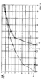
図8は、冷却流体の圧力の関数として3つの流速の曲線を示す。 FIG. 8 shows three flow rate curves as a function of cooling fluid pressure.
これらのうち、曲線1は、内燃エンジン(図1及び2)のピストン10a、10b、10c、及び10dの冷却及び潤滑ノズル8a、8b、8c、及び8d用の油供給バルブ21を有さない冷却回路の場合において、圧力の関数として冷却及び潤滑流体の流速を示す。油の通過を中断するバルブ21がないので、ゼロに等しくなく、また、略ゼロの圧力からより高い圧力まで非常に増加する油流速を認識するであろう。
Of these,
同じ図8において、曲線2は、冷却回路が、冷却流体の圧力に応答し、従って、上流圧力が閾値圧力より大きい場合に開き、また、上流圧力が閾値圧力未満である場合に完全に閉じる一般的なバルブを有する場合において、冷却流体の圧力の関数として冷却及び潤滑流体の流速を示す。例示的に、ここでは、閾値圧力は、2バールとする。冷却及び潤滑流体の流速は、ゼロ圧力と、ここでは2バールである閾値圧力の間の冷却流体の圧力に対してゼロである。冷却流体の圧力が2バールに到達すると、ピストン10a、10b、10c、及び10d(図1及び2)の冷却及び潤滑ノズル8a、8b、8c、及び8dの油供給装置の一般的なバルブは、以下のように反応する。即ち、遮断素子がコンパートメント内で動き、そして、冷却及び潤滑流体が座部の開口を通り流れることを可能にする。従って、油流速は、曲線1の流速と実質的に同じになるまで増加する。
In the same FIG. 8,
同じ図8において、曲線3は、エンジンのピストン10a−10dに油を供給するために本発明の漏れ装置を使用する場合において、冷却流体の圧力の関数として冷却流体の流速を示す。冷却流体の圧力が、基本的にゼロ圧力から増加するとき、流速が確立され、また更に、流速QA及び圧力PAにおいて曲線3上に位置付けられる点Aまで有意に増加する。圧力PAは、エンジン設計者によって選択された特定の閾値圧力に等しい(ここでは、2バール)。点Aは、低エンジン回転数(即ち、冷却流体の圧力は閾値圧力未満である)において、ピストンとライナーの間の摺動接触を滑らかにするのにちょうど十分である非ゼロ流速を確実にするよう設計者によって選択される。
In the same FIG. 8, curve 3 shows the cooling fluid flow rate as a function of the cooling fluid pressure when using the leakage device of the present invention to supply oil to the
曲線1及び3の間の領域4は、低エンジン回転数において本発明の油供給装置があることにより節約される冷却及び潤滑流体の量を示し、その結果、この油量は、クランク軸受、連接棒の大端及び小端といったエンジンのより重要な動く部品に潤滑油を差すために使用されることが可能である。
曲線3及び曲線2の間の領域5は、低エンジン回転数におけるピストンとライナーの間の摺動接触の潤滑のために使用される冷却及び潤滑流体の量を示し、これは、従って、低エンジン回転数における摺動接触への摩耗影響を大幅に減少することを可能にする。
Region 5 between curve 3 and
当業者は、図8のグラフの点Aの位置は調節可能であることを容易に理解するであろう。即ち、漏出量は、ノッチ20の深度又はラジアル孔25の直径の関数として較正される。トリガ閾値は、バネ15の選択された剛性によって決定される。
Those skilled in the art will readily understand that the position of point A in the graph of FIG. 8 is adjustable. That is, the leak rate is calibrated as a function of the depth of the
本発明は、本願に明示的に記載した実施例に限定されない。むしろ、本発明は、請求項の範囲に含まれる様々な変形及び一般化を包含する。 The invention is not limited to the embodiments explicitly described in the present application. Rather, the present invention encompasses various modifications and generalizations that fall within the scope of the claims.
7 供給チャネル
8a、8b、8c、8d 冷却及び潤滑ノズル
9a、9b、9c、9d 下流チャネル
10a、10b、10c、10d ピストン
11 ダブルノズル
12 シングルノズル
13 上流チャネル
14 下流チャネル
15 バネ
16 遮断素子
17 コンパートメント
18 開口
19 座部
20 ノッチ
21 バルブ
21a、21b、21c、21d バルブ
210 バルブ本体
22 停止部
23 流入室
24 環状室
25 ラジアル孔
26 ラジアル通路
27 横通路
28 軸方向通路
29 ピストンヘッド
7
Claims (17)
前記装置は、前記内燃エンジンの前記ピストン用の1つ以上の取り外し可能な冷却及び潤滑ノズル(8a、8b、8c、8d)を含み、
前記装置は、少なくとも1つの取り外し可能なバルブ(21)を有し、
前記バルブは、供給チャネル(7)に接続可能な上流チャネル(13)と、前記冷却流体を前記ピストンに運ぶ下流チャネル(14)を有し、
前記取り外し可能なバルブは、座部(19)の開口(18)を遮断するようコンパートメント(17)内を可動な遮断素子(16)を含む閉鎖手段を有し、
前記取り外し可能なバルブは、前記上流の圧力が閾値圧力より大きい場合には開き、前記上流の圧力が前記閾値圧力未満である場合には閉じることによって前記冷却流体の圧力に反応する装置であって、
前記取り外、し可能なバルブは更に、前記バルブの前記閉鎖手段(16、17、18、19)と並列して、前記上流チャネルを前記下流チャネルに接続する較正された漏出の手段(20、25)を有することを特徴とする装置。 In an apparatus for supplying cooling and lubricating fluid to one or more pistons (10a, 10b, 10c, 10d) of an internal combustion engine,
The apparatus includes one or more removable cooling and lubrication nozzles (8a, 8b, 8c, 8d) for the piston of the internal combustion engine;
Said device comprises at least one removable valve (21);
The valve has an upstream channel (13) connectable to a supply channel (7) and a downstream channel (14) carrying the cooling fluid to the piston;
The removable valve has closing means including a blocking element (16) movable in the compartment (17) to block the opening (18) of the seat (19);
The removable valve is a device that reacts to the pressure of the cooling fluid by opening when the upstream pressure is greater than a threshold pressure and closing when the upstream pressure is less than the threshold pressure. ,
The removable valve further comprises calibrated leakage means (20, 20) connecting the upstream channel to the downstream channel in parallel with the closing means (16, 17, 18, 19) of the valve. 25) The apparatus characterized by having.
前記遮断素子(16)は、前記座部(19)の前記開口(18)と、前記環状室(24)と連通するよう前記コンパートメント(17)に設けられた少なくとも1つのラジアル通路(26)とを同時に遮断するピストンであり、
前記較正された漏出の手段は、前記コンパートメント(17)を前記環状室(24)と永久連通させるラジアル孔(25)であり、
前記少なくとも1つのラジアル通路(26)は、前記ラジアル孔(25)の直径(D1)より大きい直径(D2)を有することを特徴とする請求項1記載の装置。 The valve (21) includes a valve body (210) having an annular chamber (24) disposed around the compartment (17) and in communication with the downstream channel (9a, 9b, 9c, 9d),
The blocking element (16) includes at least one radial passage (26) provided in the compartment (17) so as to communicate with the opening (18) of the seat (19) and the annular chamber (24). Is a piston that simultaneously blocks
The calibrated means of leakage is a radial hole (25) which makes the compartment (17) in permanent communication with the annular chamber (24);
The device according to claim 1, characterized in that the at least one radial passage (26) has a diameter (D2) which is larger than the diameter (D1) of the radial hole (25).
前記遮断素子(16)は、ヘッド(29)を有するピストンであり、
前記ピストンの前記ヘッド(29)は、前記コンパートメント(17)を前記下流チャネル(9a、9b、9c、9d)と連通させる軸方向通路(28)と連通する横通路(27)を有することを特徴とする請求項1記載の装置。 The calibrated leakage means comprises at least one notch (20) formed in the seat (19) of the valve (21);
The blocking element (16) is a piston having a head (29);
The head (29) of the piston has a lateral passage (27) in communication with an axial passage (28) that communicates the compartment (17) with the downstream channel (9a, 9b, 9c, 9d). The apparatus according to claim 1.
上流チャネル(13)及び下流チャネル(14)を有するバルブ本体(210)と、
前記上流チャネル(13)と前記下流チャネル(14)との間の座部(19)の開口(18)を遮断するようコンパートメント(17)内を可動な遮断素子(16)を含む、前記バルブ本体(210)内における閉鎖手段と、
前記閉鎖手段(16、17、18、19)と並列して、前記上流チャネル(13)を前記下流チャネル(14)に接続する較正された漏出の手段と、
を含み、
前記遮断素子(16)は、前記上流の圧力が閾値圧力より大きい場合には開き、前記上流の圧力が前記閾値圧力未満である場合には閉じることによって冷却流体の圧力に反応することを特徴とするバルブノズル。 A valve nozzle (110, 120) for implementing the device according to claim 1,
A valve body (210) having an upstream channel (13) and a downstream channel (14);
The valve body comprising a blocking element (16) movable in a compartment (17) to block an opening (18) in a seat (19) between the upstream channel (13) and the downstream channel (14) (210) closing means;
Calibrated leakage means connecting the upstream channel (13) to the downstream channel (14) in parallel with the closing means (16, 17, 18, 19);
Including
The shut-off element (16) is responsive to the pressure of the cooling fluid by opening when the upstream pressure is greater than a threshold pressure and closing when the upstream pressure is less than the threshold pressure. Valve nozzle to do.
前記遮断素子(16)は、前記座部(19)の前記開口(18)と、前記環状室(24)と連通するよう前記コンパートメント(17)に設けられた少なくとも1つのラジアル通路(26)とを同時に遮断するピストンであり、
前記較正された漏出の手段は、前記コンパートメント(17)を前記環状室(24)と永久連通させるラジアル孔(25)であり、
前記少なくとも1つのラジアル通路(26)は、前記ラジアル孔(25)の直径(D1)より大きい直径(D2)を有することを特徴とする請求項8記載のバルブノズル。 The valve body (210) includes an annular chamber (24) disposed around the compartment (17) and in communication with the downstream channel (9a, 9b, 9c, 9d);
The blocking element (16) includes at least one radial passage (26) provided in the compartment (17) so as to communicate with the opening (18) of the seat (19) and the annular chamber (24). Is a piston that simultaneously blocks
The calibrated means of leakage is a radial hole (25) which makes the compartment (17) in permanent communication with the annular chamber (24);
The valve nozzle according to claim 8, characterized in that the at least one radial passage (26) has a diameter (D2) greater than the diameter (D1) of the radial hole (25).
前記遮断素子(16)は、ヘッド(29)を有するピストンであり、
前記ピストンの前記ヘッド(29)は、前記コンパートメント(17)を前記下流チャネル(9a、9b、9c、9d)と連通させる軸方向通路(28)と連通する横通路(27)を有することを特徴とする請求項8記載のバルブノズル。 The calibrated leakage means comprises at least one notch (20) formed in the seat (19) of the valve (21);
The blocking element (16) is a piston having a head (29);
The head (29) of the piston has a lateral passage (27) in communication with an axial passage (28) that communicates the compartment (17) with the downstream channel (9a, 9b, 9c, 9d). The valve nozzle according to claim 8.
Applications Claiming Priority (1)
| Application Number | Priority Date | Filing Date | Title |
|---|---|---|---|
| FR0504702A FR2885170B1 (en) | 2005-05-02 | 2005-05-02 | CONTROLLED LEAK CHECK VALVE FOR PISTON COOLING SPRAY |
Publications (2)
| Publication Number | Publication Date |
|---|---|
| JP2006312936A true JP2006312936A (en) | 2006-11-16 |
| JP2006312936A5 JP2006312936A5 (en) | 2007-07-12 |
Family
ID=35998395
Family Applications (1)
| Application Number | Title | Priority Date | Filing Date |
|---|---|---|---|
| JP2006123845A Pending JP2006312936A (en) | 2005-05-02 | 2006-04-27 | Controlled leakage valve for piston cooling nozzle |
Country Status (11)
| Country | Link |
|---|---|
| US (1) | US7350484B2 (en) |
| EP (1) | EP1728981A3 (en) |
| JP (1) | JP2006312936A (en) |
| KR (1) | KR100738248B1 (en) |
| CN (1) | CN1858415A (en) |
| AU (1) | AU2006201807A1 (en) |
| BR (1) | BRPI0601570A (en) |
| CA (1) | CA2544956A1 (en) |
| DE (1) | DE06356049T9 (en) |
| ES (1) | ES2276645T1 (en) |
| FR (1) | FR2885170B1 (en) |
Cited By (4)
| Publication number | Priority date | Publication date | Assignee | Title |
|---|---|---|---|---|
| JP2008232145A (en) * | 2007-03-16 | 2008-10-02 | Bontaz Centre | Cooling sprayer having valve |
| JP2009191679A (en) * | 2008-02-13 | 2009-08-27 | Ogino Kogyo Kk | Oil jet device |
| JP2012225301A (en) * | 2011-04-21 | 2012-11-15 | Toyota Motor Corp | Actuator for driving internal combustion engine variable valve mechanism, and actuator oil injection control device |
| CN105221232A (en) * | 2015-11-05 | 2016-01-06 | 重庆驰龙摩托车配件有限公司 | A kind of motorcycle twin cylinder engine piston cooling device |
Families Citing this family (24)
| Publication number | Priority date | Publication date | Assignee | Title |
|---|---|---|---|---|
| FR2885170B1 (en) | 2005-05-02 | 2007-09-21 | Bontaz Ct Sa | CONTROLLED LEAK CHECK VALVE FOR PISTON COOLING SPRAY |
| US7806234B2 (en) * | 2007-05-09 | 2010-10-05 | Toyota Motor Engineering And Manufacturing North America, Inc. | Lubricant delivery systems and methods for controlling flow in lubricant delivery systems |
| US8397749B2 (en) * | 2007-09-07 | 2013-03-19 | Metaldyne Company Llc | Piston cooling jet with tracking ball orifice |
| DE502008000983D1 (en) | 2008-01-18 | 2010-09-02 | Ford Global Tech Llc | control valve |
| FR2935771B1 (en) | 2008-09-09 | 2010-10-08 | Bontaz Centre Sa | DEVICE FOR CONTROLLING THE SUPPLY OF A SYSTEM WITH A FLUID |
| CN102985657A (en) * | 2010-04-15 | 2013-03-20 | 万国引擎知识产权有限责任公司 | Engine with electronically controlled piston cooling jets and method for controlling the same |
| CN101886570B (en) * | 2010-06-02 | 2012-02-29 | 奇瑞汽车股份有限公司 | Piston cooling spray nozzle structure |
| GB2490938A (en) * | 2011-05-19 | 2012-11-21 | Gm Global Tech Operations Inc | Method to diagnose a fault of an oil piston cooling jets valve |
| US8707927B2 (en) * | 2011-07-20 | 2014-04-29 | GM Global Technology Operations LLC | Oil squirter |
| US8387571B2 (en) * | 2011-11-04 | 2013-03-05 | Ford Global Technologies, Llc | Oil delivery system |
| ES2545753T3 (en) * | 2012-04-17 | 2015-09-15 | Fpt Industrial S.P.A. | Method for controlling a piston cooling circuit of an internal combustion engine of an industrial vehicle |
| CN102758676B (en) * | 2012-08-02 | 2014-12-10 | 三一重工股份有限公司 | Engine piston cooling nozzle, engine and engineering machinery |
| FR3004489B1 (en) | 2013-04-11 | 2017-04-28 | Bontaz Centre R & D | COOLING DEVICE FOR A REDUCED INTERNAL COMBUSTION ENGINE AND METHOD FOR MANUFACTURING SUCH A DEVICE |
| JP6216865B2 (en) * | 2013-04-11 | 2017-10-18 | ボンタ サントル エール エ デー | Apparatus for controlling fluid supply to a system to optimize fluid consumption |
| US9956508B2 (en) | 2013-04-16 | 2018-05-01 | Cummins Filtration Ip, Inc. | Filter element with air vent |
| DE102013014930A1 (en) * | 2013-09-11 | 2015-03-12 | Man Truck & Bus Ag | Control valve for a lubricant nozzle |
| GB201519640D0 (en) * | 2015-11-06 | 2015-12-23 | Gm Global Tech Operations Inc | Piston cooling jet for an internal combustion engine |
| US10590830B1 (en) * | 2018-10-23 | 2020-03-17 | GM Global Technology Operations LLC | Internal combustion engine including piston cooling jets |
| US11333140B2 (en) * | 2019-06-11 | 2022-05-17 | Caterpillar Inc. | Cooling block for multi-cylinder air compressor |
| US11248515B2 (en) * | 2019-08-02 | 2022-02-15 | Transportation Ip Holdings, Llc | Piston cooling jet system |
| USD921044S1 (en) * | 2019-08-02 | 2021-06-01 | Transportation Ip Holdings, Llc | Piston cooling apparatus |
| USD928201S1 (en) * | 2019-08-02 | 2021-08-17 | Transportation Ip Holdings, Llc | Piston cooling apparatus |
| WO2021026209A1 (en) | 2019-08-08 | 2021-02-11 | Cummins Inc. | Passive piston cooling nozzle control with low speed hot running protection |
| USD965029S1 (en) * | 2020-09-11 | 2022-09-27 | Transportation Ip Holdings, Llc | Piston cooling jet |
Family Cites Families (17)
| Publication number | Priority date | Publication date | Assignee | Title |
|---|---|---|---|---|
| DE2847057A1 (en) * | 1978-10-28 | 1980-05-08 | Daimler Benz Ag | INTERNAL COMBUSTION ENGINE WITH COOLING SYSTEM |
| JPS57126505U (en) | 1981-01-31 | 1982-08-06 | ||
| JPS57126504U (en) | 1981-01-31 | 1982-08-06 | ||
| US4364399A (en) * | 1981-02-23 | 1982-12-21 | Dashefsky Joseph H | Diagnostic instrument |
| JPS61107914U (en) | 1984-12-19 | 1986-07-09 | ||
| DE3843827A1 (en) * | 1988-12-24 | 1990-07-05 | Kloeckner Humboldt Deutz Ag | INTERNAL COMBUSTION ENGINE WITH TWO HYDRAULIC LIQUID CIRCUITS |
| DE4018363A1 (en) * | 1990-06-08 | 1991-12-12 | Wahler Gmbh & Co Gustav | PRESSURE CONTROL VALVE, ESPECIALLY FOR OIL SPRAY NOZZLES FOR INTERNAL COMBUSTION ENGINES |
| JPH0552225U (en) * | 1991-12-16 | 1993-07-13 | いすゞ自動車株式会社 | Oil jet for piston cooling |
| JP3477316B2 (en) * | 1996-06-05 | 2003-12-10 | 日産自動車株式会社 | Internal combustion engine piston cooling device |
| KR100380211B1 (en) * | 1999-12-07 | 2003-04-16 | 현대자동차주식회사 | Oil jet apparatus for cooling of piston |
| FR2827009B1 (en) * | 2001-07-04 | 2003-12-12 | Bontaz Centre Sa | PISTON COOLING JET |
| JP2004346766A (en) * | 2003-05-20 | 2004-12-09 | Toyota Motor Corp | Oil feeder for internal combustion engine |
| US7152623B2 (en) * | 2003-09-09 | 2006-12-26 | Metaldyne Company, Llc | Fluid jet for providing fluid under pressure to a desired location |
| FR2859756B1 (en) * | 2003-09-16 | 2007-09-21 | Bontaz Centre Sa | COOLING DEVICE FOR MOTOR PISTONS. |
| US6955142B2 (en) * | 2004-02-25 | 2005-10-18 | General Motors Corporation | Piston and cylinder oil squirter rail and system |
| DE102004017909A1 (en) * | 2004-04-13 | 2005-11-10 | Bayerische Motoren Werke Ag | Device for cooling at least one piston of an internal combustion engine |
| FR2885170B1 (en) | 2005-05-02 | 2007-09-21 | Bontaz Ct Sa | CONTROLLED LEAK CHECK VALVE FOR PISTON COOLING SPRAY |
-
2005
- 2005-05-02 FR FR0504702A patent/FR2885170B1/en active Active
-
2006
- 2006-04-26 DE DE06356049T patent/DE06356049T9/en active Active
- 2006-04-26 EP EP06356049A patent/EP1728981A3/en not_active Withdrawn
- 2006-04-26 CA CA002544956A patent/CA2544956A1/en not_active Abandoned
- 2006-04-26 ES ES06356049T patent/ES2276645T1/en active Pending
- 2006-04-27 JP JP2006123845A patent/JP2006312936A/en active Pending
- 2006-05-01 AU AU2006201807A patent/AU2006201807A1/en not_active Abandoned
- 2006-05-02 US US11/416,292 patent/US7350484B2/en not_active Expired - Fee Related
- 2006-05-02 BR BRPI0601570-0A patent/BRPI0601570A/en not_active IP Right Cessation
- 2006-05-02 KR KR1020060039550A patent/KR100738248B1/en active IP Right Grant
- 2006-05-08 CN CNA2006100785159A patent/CN1858415A/en active Pending
Cited By (5)
| Publication number | Priority date | Publication date | Assignee | Title |
|---|---|---|---|---|
| JP2008232145A (en) * | 2007-03-16 | 2008-10-02 | Bontaz Centre | Cooling sprayer having valve |
| JP4629119B2 (en) * | 2007-03-16 | 2011-02-09 | ボンタ セントル | Cooling sprayer with valve |
| JP2009191679A (en) * | 2008-02-13 | 2009-08-27 | Ogino Kogyo Kk | Oil jet device |
| JP2012225301A (en) * | 2011-04-21 | 2012-11-15 | Toyota Motor Corp | Actuator for driving internal combustion engine variable valve mechanism, and actuator oil injection control device |
| CN105221232A (en) * | 2015-11-05 | 2016-01-06 | 重庆驰龙摩托车配件有限公司 | A kind of motorcycle twin cylinder engine piston cooling device |
Also Published As
| Publication number | Publication date |
|---|---|
| CN1858415A (en) | 2006-11-08 |
| DE06356049T9 (en) | 2008-06-05 |
| EP1728981A2 (en) | 2006-12-06 |
| BRPI0601570A (en) | 2007-07-17 |
| DE06356049T1 (en) | 2007-05-10 |
| KR20060114652A (en) | 2006-11-07 |
| US7350484B2 (en) | 2008-04-01 |
| KR100738248B1 (en) | 2007-07-12 |
| FR2885170A1 (en) | 2006-11-03 |
| FR2885170B1 (en) | 2007-09-21 |
| CA2544956A1 (en) | 2006-11-02 |
| US20060243226A1 (en) | 2006-11-02 |
| AU2006201807A1 (en) | 2006-11-16 |
| EP1728981A3 (en) | 2008-08-20 |
| ES2276645T1 (en) | 2007-07-01 |
Similar Documents
| Publication | Publication Date | Title |
|---|---|---|
| JP2006312936A (en) | Controlled leakage valve for piston cooling nozzle | |
| US6672262B2 (en) | Piston cooling nozzle | |
| CN104736810A (en) | Internal combustion engine | |
| JP2011058458A (en) | Oil supply device of internal combustion engine | |
| US20190107033A1 (en) | Valve for adjusting a cooling fluid flow for piston cooling | |
| FI122862B (en) | Piston pump with anti-deposit protection | |
| JP2008101594A (en) | Lubricating oil supply structure for piston and piston ring | |
| JP2014009669A (en) | Lubricant supply device of internal combustion engine | |
| US20180156082A1 (en) | Regulator assembly | |
| US20200018199A1 (en) | Oil supply device | |
| JP2001520719A (en) | Fuel injection pumps for internal combustion engines, especially large and low speed marine diesel engines | |
| RU2739431C1 (en) | Lubrication system with oil passage and nozzle | |
| JP6885348B2 (en) | Oil jet device | |
| JP6258773B2 (en) | Internal combustion engine flow control valve | |
| JP7205211B2 (en) | high pressure pump | |
| JP2020051268A (en) | Oil supply device for internal combustion engine | |
| JPS6327527B2 (en) | ||
| JP2006170066A (en) | Oil supply device | |
| KR200476236Y1 (en) | Apparatus for cooling oil gallery of engine | |
| RU2777178C2 (en) | Valve for adjustment of cooling medium flow for cooling pistons | |
| MXPA06004839A (en) | Controlled leakage valve for piston cooling nozzle | |
| JP2014101763A (en) | Oil supply device for internal combustion engine | |
| KR101039528B1 (en) | Apparatus to cool the piston using counter webs | |
| JPH0968042A (en) | Oil injection device for four-cycle engine | |
| KR101294045B1 (en) | Hydraulic chain tensioner |
Legal Events
| Date | Code | Title | Description |
|---|---|---|---|
| A521 | Request for written amendment filed |
Free format text: JAPANESE INTERMEDIATE CODE: A523 Effective date: 20070529 |
|
| A131 | Notification of reasons for refusal |
Free format text: JAPANESE INTERMEDIATE CODE: A131 Effective date: 20090526 |
|
| A02 | Decision of refusal |
Free format text: JAPANESE INTERMEDIATE CODE: A02 Effective date: 20091110 |