JP2006293003A - Process cartridge and electrophotographic image forming apparatus - Google Patents
Process cartridge and electrophotographic image forming apparatus Download PDFInfo
- Publication number
- JP2006293003A JP2006293003A JP2005113398A JP2005113398A JP2006293003A JP 2006293003 A JP2006293003 A JP 2006293003A JP 2005113398 A JP2005113398 A JP 2005113398A JP 2005113398 A JP2005113398 A JP 2005113398A JP 2006293003 A JP2006293003 A JP 2006293003A
- Authority
- JP
- Japan
- Prior art keywords
- contact
- cartridge
- process cartridge
- main body
- memory
- Prior art date
- Legal status (The legal status is an assumption and is not a legal conclusion. Google has not performed a legal analysis and makes no representation as to the accuracy of the status listed.)
- Granted
Links
Images


Classifications
-
- G—PHYSICS
- G03—PHOTOGRAPHY; CINEMATOGRAPHY; ANALOGOUS TECHNIQUES USING WAVES OTHER THAN OPTICAL WAVES; ELECTROGRAPHY; HOLOGRAPHY
- G03G—ELECTROGRAPHY; ELECTROPHOTOGRAPHY; MAGNETOGRAPHY
- G03G21/00—Arrangements not provided for by groups G03G13/00 - G03G19/00, e.g. cleaning, elimination of residual charge
- G03G21/16—Mechanical means for facilitating the maintenance of the apparatus, e.g. modular arrangements
- G03G21/18—Mechanical means for facilitating the maintenance of the apparatus, e.g. modular arrangements using a processing cartridge, whereby the process cartridge comprises at least two image processing means in a single unit
- G03G21/1839—Means for handling the process cartridge in the apparatus body
- G03G21/1867—Means for handling the process cartridge in the apparatus body for electrically connecting the process cartridge to the apparatus, electrical connectors, power supply
-
- G—PHYSICS
- G03—PHOTOGRAPHY; CINEMATOGRAPHY; ANALOGOUS TECHNIQUES USING WAVES OTHER THAN OPTICAL WAVES; ELECTROGRAPHY; HOLOGRAPHY
- G03G—ELECTROGRAPHY; ELECTROPHOTOGRAPHY; MAGNETOGRAPHY
- G03G21/00—Arrangements not provided for by groups G03G13/00 - G03G19/00, e.g. cleaning, elimination of residual charge
- G03G21/16—Mechanical means for facilitating the maintenance of the apparatus, e.g. modular arrangements
- G03G21/1642—Mechanical means for facilitating the maintenance of the apparatus, e.g. modular arrangements for connecting the different parts of the apparatus
- G03G21/1652—Electrical connection means
-
- G—PHYSICS
- G03—PHOTOGRAPHY; CINEMATOGRAPHY; ANALOGOUS TECHNIQUES USING WAVES OTHER THAN OPTICAL WAVES; ELECTROGRAPHY; HOLOGRAPHY
- G03G—ELECTROGRAPHY; ELECTROPHOTOGRAPHY; MAGNETOGRAPHY
- G03G21/00—Arrangements not provided for by groups G03G13/00 - G03G19/00, e.g. cleaning, elimination of residual charge
- G03G21/16—Mechanical means for facilitating the maintenance of the apparatus, e.g. modular arrangements
- G03G21/18—Mechanical means for facilitating the maintenance of the apparatus, e.g. modular arrangements using a processing cartridge, whereby the process cartridge comprises at least two image processing means in a single unit
- G03G21/1875—Mechanical means for facilitating the maintenance of the apparatus, e.g. modular arrangements using a processing cartridge, whereby the process cartridge comprises at least two image processing means in a single unit provided with identifying means or means for storing process- or use parameters, e.g. lifetime of the cartridge
- G03G21/1878—Electronically readable memory
- G03G21/1882—Electronically readable memory details of the communication with memory, e.g. wireless communication, protocols
- G03G21/1885—Electronically readable memory details of the communication with memory, e.g. wireless communication, protocols position of the memory; memory housings; electrodes
-
- G—PHYSICS
- G03—PHOTOGRAPHY; CINEMATOGRAPHY; ANALOGOUS TECHNIQUES USING WAVES OTHER THAN OPTICAL WAVES; ELECTROGRAPHY; HOLOGRAPHY
- G03G—ELECTROGRAPHY; ELECTROPHOTOGRAPHY; MAGNETOGRAPHY
- G03G2221/00—Processes not provided for by group G03G2215/00, e.g. cleaning or residual charge elimination
- G03G2221/16—Mechanical means for facilitating the maintenance of the apparatus, e.g. modular arrangements and complete machine concepts
- G03G2221/1651—Mechanical means for facilitating the maintenance of the apparatus, e.g. modular arrangements and complete machine concepts for connecting the different parts
- G03G2221/166—Electrical connectors
-
- G—PHYSICS
- G03—PHOTOGRAPHY; CINEMATOGRAPHY; ANALOGOUS TECHNIQUES USING WAVES OTHER THAN OPTICAL WAVES; ELECTROGRAPHY; HOLOGRAPHY
- G03G—ELECTROGRAPHY; ELECTROPHOTOGRAPHY; MAGNETOGRAPHY
- G03G2221/00—Processes not provided for by group G03G2215/00, e.g. cleaning or residual charge elimination
- G03G2221/16—Mechanical means for facilitating the maintenance of the apparatus, e.g. modular arrangements and complete machine concepts
- G03G2221/18—Cartridge systems
- G03G2221/183—Process cartridge
- G03G2221/1884—Projections on process cartridge for guiding mounting thereof in main machine
Landscapes
- Engineering & Computer Science (AREA)
- Physics & Mathematics (AREA)
- General Physics & Mathematics (AREA)
- Computer Vision & Pattern Recognition (AREA)
- Computer Networks & Wireless Communication (AREA)
- Electrophotography Configuration And Component (AREA)
Abstract
Description
本発明はプロセスカートリッジ及びこれを用いた電子写真画像形成装置に関するものである。 The present invention relates to a process cartridge and an electrophotographic image forming apparatus using the same.
電子写真画像形成装置において、電子写真感光体ドラムやプロセス手段を一体的にカートリッジ化したプロセスカートリッジ方式によれば、電子写真画像形成装置のメンテナンスをサービスマンによらずユーザ自身で行うことができる。従って、操作性を格段に向上することができた。そこで、このプロセスカートリッジ方式は、電子写真画像形成装置において広く用いられている。 In the electrophotographic image forming apparatus, according to the process cartridge system in which the electrophotographic photosensitive drum and the process means are integrally formed as a cartridge, maintenance of the electrophotographic image forming apparatus can be performed by the user himself / herself without depending on the service person. Therefore, the operability can be remarkably improved. Therefore, this process cartridge system is widely used in electrophotographic image forming apparatuses.
また今日ではプロセスカートリッジに、電子写真画像形成装置の装置本体に伝達するための情報を記憶するメモリ(ICメモリ等)を搭載しているものがある。そして、プロセスカートリッジを装置本体に装着した際に、装置本体とプロセスカートリッジとが情報をやりとりすることができるようにしている。これにより、カートリッジの使用状況等の状態を装置本体の制御部に報知するものが提案されている(特許文献1)。 Today, some process cartridges are equipped with a memory (such as an IC memory) that stores information to be transmitted to the main body of the electrophotographic image forming apparatus. When the process cartridge is mounted on the apparatus main body, the apparatus main body and the process cartridge can exchange information. Accordingly, there has been proposed one that notifies the controller of the apparatus main body of the state of use or the like of the cartridge (Patent Document 1).
上記プロセスカートリッジに搭載したメモリに、プロセスカートリッジのロット番号、画像形成装置の特性およびプロセス手段の特性等の情報を登録する。これによって、装置本体あるいはプロセスカートリッジのメンテナンスを容易にする。さらに、メモリに記録された情報に応じて画像形成の制御を行う。これによって、最良の条件で画像形成が行われるようになってきた。 Information such as the process cartridge lot number, the characteristics of the image forming apparatus, and the characteristics of the process means is registered in the memory mounted on the process cartridge. This facilitates maintenance of the apparatus main body or the process cartridge. Further, image formation is controlled according to information recorded in the memory. As a result, image formation has been performed under the best conditions.
また画像形成装置においては、プロセスカートリッジに搭載されたメモリと画像形成装置本体を電気的に接続するための電気接続方法としては、コネクタやバネ材による接点を用いて接続する接触式の電気接続方法が知られている。これは、構成が簡単で、コスト的にも有利だからである(特許文献2)。 In the image forming apparatus, as an electrical connection method for electrically connecting the memory mounted on the process cartridge and the image forming apparatus main body, a contact-type electrical connection method for connecting using a contact using a connector or a spring material It has been known. This is because the configuration is simple and advantageous in terms of cost (Patent Document 2).
メモリのプロセスカートリッジへの固定方法としても様々な方法が知られている。そのひとつはメモリをプロセスカートリッジの枠体に両面テープ等で固定する方法である。貼付け面に比較的広い面を設けることができる場合に有効である。また、プロセスカートリッジと画像形成装置との間での信号のやり取りを非接触で行う場合、メモリを枠体に直接インサート成形する方法や熱溶着で固定する方法が知られている(特許文献3)。 Various methods are known as a method for fixing the memory to the process cartridge. One of them is a method of fixing the memory to the frame of the process cartridge with a double-sided tape or the like. This is effective when a relatively wide surface can be provided on the pasting surface. In addition, when the signal exchange between the process cartridge and the image forming apparatus is performed in a non-contact manner, there are known a method in which a memory is directly inserted into a frame body and a method in which the memory is fixed by thermal welding (Patent Document 3). .
本発明は上記従来技術を更に発展させたものである。 The present invention is a further development of the above prior art.
本発明の目的は、プロセスカートリッジにカートリッジ電気接点を容易に設けることが可能なプロセスカートリッジ及びこれを用いる電子写真画像形成装置を提供するものである。 An object of the present invention is to provide a process cartridge and an electrophotographic image forming apparatus using the process cartridge in which cartridge electrical contacts can be easily provided on the process cartridge.
本発明の他の目的は、プロセスカートリッジに設けたカートリッジ電気接点を確実にカートリッジ表面に露出させて本体接点と電気的接続が可能なプロセスカートリッジ及びこれを用いる電子写真画像形成装置を提供するものである。 Another object of the present invention is to provide a process cartridge which can be electrically connected to a main body contact by reliably exposing a cartridge electrical contact provided on the process cartridge to the surface of the cartridge, and an electrophotographic image forming apparatus using the process cartridge. is there.
本発明の他の目的は、プロセスカートリッジへの接点部材の組み付け及び分解が容易なプロセスカートリッジ及びこれを用いる電子写真画像形成装置を提供するものである。 Another object of the present invention is to provide a process cartridge in which a contact member can be easily assembled and disassembled to a process cartridge, and an electrophotographic image forming apparatus using the process cartridge.
上記課題を解決するための本発明における代表的な手段は、本体電気接点を有する電子写真画像形成装置本体に着脱自在なプロセスカートリッジにおいて、電子写真感光体と、前記電子写真感光体に作用するプロセス手段と、前記プロセスカートリッジに関する情報を記憶するメモリと、前記メモリの情報を前記電子写真画像形成装置本体に伝達するために前記本体電気接点と電気的に接続可能なカートリッジ電気接点を有する接点部材と、前記接点部材を支持するための接点支持手段と、を有し、前記接点支持手段は、前記接点部材の前記電子写真感光体の長手方向である幅方向の移動を規制するための所定間隔を有する第1規制部と、前記接点部材の前記幅方向と直交する厚さ方向の移動を規制するための所定間隔を有する第2規制部と、前記幅方向及び前記厚さ方向と直交する高さ方向の一方向が開口した開口部とを有し、前記接点部材を前記開口部から前記接点支持手段へ挿入装着可能であることを特徴とする。 A typical means in the present invention for solving the above problems is an electrophotographic photosensitive member and a process acting on the electrophotographic photosensitive member in a process cartridge which is detachable from the main body of the electrophotographic image forming apparatus having a main body electrical contact. Means, a memory for storing information relating to the process cartridge, and a contact member having a cartridge electrical contact that can be electrically connected to the body electrical contact for transmitting the information in the memory to the electrophotographic image forming apparatus body. Contact support means for supporting the contact member, and the contact support means has a predetermined interval for restricting movement of the contact member in the width direction which is the longitudinal direction of the electrophotographic photosensitive member. A first restricting part having a second restricting part having a predetermined interval for restricting movement of the contact member in a thickness direction orthogonal to the width direction; An opening that opens in one direction in the height direction perpendicular to the width direction and the thickness direction, and the contact member can be inserted and attached to the contact support means from the opening. .
本発明にあっては、接点部材を接点支持手段の開口部から挿入すると、第1規制部と第2規制部によって、接点部材の移動が規制される。このため、接点部材を簡単に取り付けることができる。 In the present invention, when the contact member is inserted from the opening of the contact support means, the movement of the contact member is restricted by the first restricting portion and the second restricting portion. For this reason, a contact member can be easily attached.
〔第1実施形態〕
次に本発明の一実施形態に係るプロセスカートリッジ及びこれを用いる電子写真画像形成装置について図面を参照して説明する。
[First Embodiment]
Next, a process cartridge and an electrophotographic image forming apparatus using the same according to an embodiment of the present invention will be described with reference to the drawings.
[多色画像形成装置の全体構成]
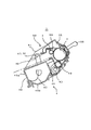
まず多色画像形成装置の全体構成について、図1を参照して概要説明する。なお、図1は多色画像形成装置の一態様であるフルカラーレーザービームプリンタの全体構成を示す縦断面図である。
[Overall configuration of multicolor image forming apparatus]
First, the overall configuration of the multicolor image forming apparatus will be outlined with reference to FIG. FIG. 1 is a longitudinal sectional view showing the overall configuration of a full-color laser beam printer which is an embodiment of a multicolor image forming apparatus.
図1に示す画像形成装置本体(以下「装置本体」という)100は、垂直方向に並設された4個のドラム形状の電子写真感光体である電子写真感光体ドラム1(1a,1b,1c,1d)を備えている。この電子写真感光体ドラム(以下「感光体ドラム」という)1は、駆動手段(不図示)によって、同図中、反時計回りに回転駆動される。感光体ドラム1の周囲には、その回転方向に従って順に、感光体ドラム1表面を均一に帯電する帯電装置2(2a,2b,2c,2d)、感光体ドラム1に形成した静電潜像にトナーを付着させてトナー像として現像する現像装置4(4a,4b,4c,4d)、感光体ドラム1上のトナー像を記録媒体Sに転写させる静電転写装置5、転写後の感光体ドラム1表面に残った転写残トナーを除去するクリーニング装置6(6a,6b,6c,6d)等が配設されている。
An image forming apparatus main body (hereinafter referred to as “apparatus main body”) 100 shown in FIG. 1 includes four electrophotographic photosensitive drums 1 (1a, 1b, 1c) which are four drum-shaped electrophotographic photosensitive bodies arranged in parallel in the vertical direction. , 1d). This electrophotographic photosensitive drum (hereinafter referred to as “photosensitive drum”) 1 is rotationally driven counterclockwise in the drawing by a driving means (not shown). Around the
ここで、感光体ドラム1と帯電装置2、現像装置4、クリーニング装置6は一体的にカートリッジ化されプロセスカートリッジ(以下「カートリッジ」という)7を形成している。
Here, the
また、装置本体の奥側には画像情報に基づいて感光体ドラム1に選択的な露光を行い、感光体ドラム1に潜像を形成するためのスキャナユニット3(3a,3b,3c,3d)が設けられている。
A scanner unit 3 (3a, 3b, 3c, 3d) for selectively exposing the
静電転写装置5には、すべての感光体ドラム1a,1b,1c,1dに対向し、接するように循環移動する静電転写ベルト11が配設されている。静電転写ベルト11には樹脂フィルムや、ゴム基層上に樹脂層が設けられた多層フィルム状部材が用いられている。この静電転写ベルト11は、駆動ローラ13、従動ローラ14a,14b、テンションローラ15に張架されている。そして、静電吸着ローラ22へのバイアス印加によって静電転写ベルト11の外周面に記録媒体Sを静電吸着して上記感光体ドラム1に記録媒体Sを接触させるべく循環移動する。これにより、記録媒体Sは静電転写ベルト11により転写位置まで搬送され、感光体ドラム1上のトナー像を転写される。
The electrostatic transfer device 5 is provided with an electrostatic transfer belt 11 that circulates and moves so as to face and contact all the photosensitive drums 1a, 1b, 1c, and 1d. For the electrostatic transfer belt 11, a resin film or a multilayer film-like member having a resin layer provided on a rubber base layer is used. The electrostatic transfer belt 11 is stretched around a driving roller 13, driven rollers 14a and 14b, and a
この静電転写ベルト11の内側に当接し、4個の感光体ドラム1a,1b,1c,1dに対向した位置に転写ローラ12(12a,12b,12c,12d)が並設されている。これら転写ローラ12に、転写時に感光体ドラム1上のトナー像と逆極性のバイアスが印加することで、前記感光体ドラム1上のトナー像が記録媒体Sに転写される。
Transfer rollers 12 (12a, 12b, 12c, 12d) are arranged side by side in contact with the inside of the electrostatic transfer belt 11 and facing the four photosensitive drums 1a, 1b, 1c, 1d. A bias having a polarity opposite to that of the toner image on the
給送部16は、画像形成部に記録媒体Sを給送搬送するものであり、前記静電転写ベルト11とともに記録媒体Sを搬送する搬送手段を構成するものである。この給送部16には複数枚の記録媒体Sを収納した給送カセット17が装着されている。画像形成時には給送ローラ18(半月ローラ)、レジストローラ19が画像形成動作に応じて駆動回転する。これにより、給送カセット17内の記録媒体Sを1枚ずつ分離給送する。そして、レジストローラ19によって静電転写ベルト11の回転と画像書出し位置の同期をとって、静電転写ベルト11へと給送されていく。
The
定着部20は、記録媒体Sに転写された複数色のトナー画像を定着させるものであり、回転する加熱ローラ21aと、これに圧接して記録媒体Sに熱及び圧力を与える加圧ローラ21bとからなる。 The fixing unit 20 fixes the toner images of a plurality of colors transferred to the recording medium S, a heating roller 21a that rotates, and a pressure roller 21b that presses and applies heat and pressure to the recording medium S. Consists of.
画像形成の動作としては、カートリッジ7a,7b,7c,7dが、印字タイミングに合わせて順次駆動される。そして、その駆動に応じて感光体ドラム1a,1b,1c,1dが、反時計回り方向に回転駆動される。そして、各々のカートリッジ7に対応するスキャナユニット3が順次駆動される。この駆動により、周面が一様に帯電された感光体ドラム1に静電潜像が形成される。そして、前記潜像が現像装置4によってトナー現像される。
As an image forming operation, the cartridges 7a, 7b, 7c, and 7d are sequentially driven in accordance with the print timing. In response to the drive, the photosensitive drums 1a, 1b, 1c, and 1d are driven to rotate counterclockwise. Then, the
前記画像形成と同期して、記録媒体Sが搬送手段によって感光体ドラム1と対向する位置に搬送される。そして、静電転写ベルト11を挟んで各感光体ドラム1と対向した転写ローラ12(12a,12b,12c,12d)へ転写バイアスを印加することで、各感光体ドラム1上の各色現像剤像が記録媒体Sに重畳転写される。これによって、記録媒体Sにカラー画像を形成される。
In synchronization with the image formation, the recording medium S is conveyed to a position facing the
4色のトナー像を転写された記録媒体Sは、ベルト駆動ローラ13の曲率により静電転写ベルト11から曲率分離され、定着部20に搬入される。記録媒体Sは、定着部20で上記トナー像を熱定着された後、排出ローラ23によって、排出部24から画像面を下にした状態で本体外に排出される。 The recording medium S to which the four color toner images are transferred is separated from the electrostatic transfer belt 11 by the curvature of the belt driving roller 13 and is carried into the fixing unit 20. After the toner image is heat-fixed by the fixing unit 20, the recording medium S is discharged out of the main body by the discharge roller 23 with the image surface down.
[カートリッジの構成]
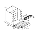
次に本実施形態に係るカートリッジについて、図2及び図3により詳細に説明する。図2及び図3はトナーを収納したカートリッジ7の主断面および斜視図を示している。なお、イエロー、マゼンダ、シアン、ブラックの各カートリッジ7a,7b,7c,7dは同一構成である。
[Cartridge configuration]
Next, the cartridge according to the present embodiment will be described in detail with reference to FIGS. 2 and 3 show a main cross section and a perspective view of the
カートリッジ7は、感光体ドラム1と、帯電手段およびクリーニング手段を備えたクリーナユニット50、および感光体ドラム1上の静電潜像を現像する現像装置を構成する現像ユニット4に分かれている。
The
クリーナユニット50は、感光体ドラム1が軸受部材を介してクリーニング枠体51に回動自在に取り付けられている。感光体ドラム1の周上には、感光体ドラム1の外周面に設けられた感光層を一様に帯電させるための一次帯電装置2が設けられている。また、感光体ドラム1の周上には、および転写後に感光体ドラム1上に残った現像剤(残留トナー)を除去するためのクリーニングブレード(以下、「ブレード」という)60が配設されている。さらに、ブレード60によって感光体ドラム1表面から除去された残留トナーは、ブレード60上方に設けられた残留トナー収納部55に納められる。
In the
現像ユニット4は、感光体ドラム1と微少間隙を保持して矢印方向に回転する現像スリーブ40、およびトナーを収容する現像枠体45a,45bとから構成される。
The developing
現像枠体45a,45bは結合され(超音波溶着等により結合)、現像容器ユニット46となる。
The developing frame bodies 45a and 45b are coupled (coupled by ultrasonic welding or the like) to form the developing
現像スリーブ40は軸受け部材を介して回転自在に現像容器ユニット46に支持されている。また現像スリーブ40の周上には、現像スリーブ40と接触して矢印方向に回転するトナー供給ローラ43と現像ブレード44がそれぞれ配置されている。さらに現像容器ユニット46内には収容されたトナーを撹拌するとともにトナー供給ローラ43に搬送するためのトナー搬送機構42が設けられている。
The developing
そして現像ユニット4は、現像容器ユニット46の両端に設けた結合穴47とクリーナユニット50のクリーニング枠体51両端に設けた支持穴52を合わせ、クリーナユニット50両端からピン49を差し込む。それによって現像ユニット4全体がクリーナユニット50に対して揺動自在に支持された吊り構造となっている。
In the developing
また、支持穴52を中心に現像スリーブ40が感光体ドラム1に接触するように加圧ばね(図示せず)によって現像ユニット4が常に付勢されている。
Further, the developing
[装置本体に対するカートリッジの装着構成]
次に、装置本体100に対するカートリッジ7の装着部について、図4を用いて説明する。図4に示すように、装置本体100には前扉101が設けられていて、回動可能に設けられている。また、前扉101の奥には静電転写装置5が回動可能に設けられている。これら前扉101、静電転写装置5が開いた状態で、カートリッジ7は、装置本体100に対して着脱可能となる。カートリッジ7の両端部の感光体ドラム支持部近傍には把手部材90が設けられていて、カートリッジ着脱時には本体前扉側に突出している。
[Installation configuration of cartridge in the main unit]
Next, the mounting portion of the
カートリッジ7は、装置本体100内に設けられているガイドレール部102,103と、カートリッジ7の長手方向両側面に設けられた挿入ガイド部53(図3もあわせて参照)とが係合することにより、装置本体100に対し着脱可能となる。
In the
そして、ユーザがカートリッジ7の装着を完了し、前扉101を閉めると加圧力(不図示)がカートリッジ7に付与される。さらに画像形成される時の駆動力により、装置本体100に対するカートリッジ7の位置が決まる。
When the user completes the mounting of the
[メモリ]
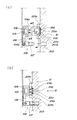
本実施形態のカートリッジ7には、カートリッジ7のロット番号、画像形成装置の特性およびプロセス手段の特性等の情報を記憶するメモリ200が設けられている。次に前記メモリについて、図3、図5、図7を用いて説明する。なお、図5はメモリの単品を表した斜視図であり、図7は装置本体側の電気接点周囲を表す斜視図である。
[memory]
The
本実施形態のカートリッジ7はメモリ200に格納した情報を装置本体100とやりとりすることで、カートリッジ7の使用状況等の状態を装置本体100に設けられた制御部(不図示)に報知する。そして、前記情報に応じて画像形成の制御を行う。これによって、最良の条件で画像形成を行う。
The
本実施形態のメモリ200は、図5に示すように、メモリ基板202の一方面側に取り付けられている。このメモリ基板202は四角形の板部材であり、他方面側に一対のカートリッジ電気接点201a,201bを有する接点部材である。そして前記メモリ基板202は、クリーニングユニット50に設けられた後述する接点支持手段に取り付けられている。
As shown in FIG. 5, the
前記カートリッジ電気接点201a,201bは、カートリッジ7が装置本体100に装着された際に、装置本体側の本体電気接点104a,104bと電気的に接続する。そして、前記電気接点104a,104bを介して前記メモリ200に記憶した情報を装置本体100に伝達する。
The cartridge
前記メモリ基板202は、カートリッジ電気接点201a,202bが外側になるように、クリーニング枠体51に取り付けられている。尚、カートリッジ7の装着方向に対して略下流側にカートリッジ電気接点201a,201bが面するように配置されている。
The
なお、本実施形態にあっては、前記メモリ基板202を取り付けたクリーニングユニット50の長手方向において、前記カートリッジ電気接点201a,202bの近傍に嵌合溝203が設けられている。この嵌合溝203は、カートリッジ7が装置本体100に装着される際に、本体電気接点104a,104bに対する前記カートリッジ電気接点201a,202bの位置決めを行うためにカートリッジ7に設けられた位置決め部材と係合する被位置決め部となる。
In the present embodiment, a
[メモリ基板の取り付け及び取り外し構成]
次にメモリ基板202のカートリッジへの取り付け及び取り外し構成について、図6及び図8を用いて説明する。
[Memory board installation and removal configuration]
Next, a configuration for attaching and detaching the
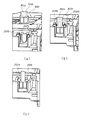
図6はメモリ基板202のカートリッジ7への取り付け、分解方法を順を追ってあらわした斜視説明図である。図8はカートリッジの装着過程を追ってカートリッジと電気接点ユニットの一部を長手方向で切った断面図である。
FIG. 6 is a perspective explanatory view showing the attachment and disassembly method of the
なお、図6(a)に示すように、感光体ドラムの回転軸線方向であるドラム長手方向(矢印X方向)をメモリ基板202の幅方向とする。また、前記幅方向と直交するカートリッジ挿脱方向(矢印Y方向)をメモリ基板202の厚さ方向とする。また、前記幅方向及び厚さ方向と直交する方向(矢印Z方向)をメモリ基板202の高さ方向とする。
As shown in FIG. 6A, the drum longitudinal direction (arrow X direction), which is the rotational axis direction of the photosensitive drum, is the width direction of the
クリーニング枠体51にはメモリ基板202を支持するための接点支持手段204が形成されている。この接点支持手段204の中央付近にはメモリ基板202の一面側に設けたメモリ200を逃げるための逃げ凹部205が形成されている。そして、前記逃げ凹部205の周囲にはカートリッジ電気接点201a,201bが本体側電気接点104a,104bに接触した時に接点圧を受け、メモリ基板202が厚さ方向に移動するのを規制する受け面206が設けられている。
The
更にドラム長手方向で受け面206の外側には断面L字形状の一対の規制部材220a,220bが対向するようにクリーニング枠体51と一体的に設けられている(図8の断面図参照)。これにより、前記受け面206を挟んで一対のスリット部207a,207bが形成されている。このスリット部207a,207bによって構成される本実施形態の接点支持手段は、基板高さ方向の一方側である上方が開口した開口部211a,211bを有するスリット形状をしている。
Further, a pair of restricting members 220a and 220b having an L-shaped cross section are provided integrally with the
メモリ基板202をカートリッジ7に取り付ける場合には、前記開口部211a,211bからメモリ基板202のカートリッジ電気接点201a,201bを挟んだ両端部の稜線202a,202bをそれぞれスリット部207a,207bに係合して挿入する。本実施形態ではメモリ基板202は四角形であるが、前記係合構成はメモリ基板202の形によらない。すなわち、カートリッジ電気接点201a,201bを挟んだメモリ基板202の一対の稜線をクリーニング枠体51に形成された一対のスリット部207a,207bに係合できればよい。
When the
上記のようにメモリ基板202をスリット部207a,207bに挿入すると、メモリ基板202の幅方向の移動が所定間隔を有する第1規制部によって規制される。また、メモリ基板202の厚さ方向の移動が所定間隔を有する第2規制部によって規制される。
When the
すなわち、対向して設けられた一対の規制部材220a,220bの基板幅方向の対向内面間によって所定間隔を有する第1規制部が構成されている。また、前記受け面206と規制部材220a,220bの厚さ方向内面間によって所定間隔を有する第2規制部が構成されている。
That is, a first restricting portion having a predetermined interval is formed by the opposing inner surfaces in the substrate width direction of the pair of restricting members 220a and 220b provided facing each other. Further, a second restricting portion having a predetermined interval is formed by the receiving
これにより、メモリ基板202をスリット部207a,207bに挿入すると、メモリ基板202の基板幅方向の移動は規制部材220a,220bの幅方向対向内面によって規制される。また、メモリ基板202は基板厚さ方向の移動は前記受け面206と規制部材220a,220bの厚さ方向内面で規制される。
Accordingly, when the
ここで、前記第2規制部の間隔、すなわち受け面206と規制部材220a,220bの厚さ方向内面間の間隔W1は、メモリ基板202の厚さ方向長さW2よりもやや広めに構成されている(W1>W2)。また、前記第1規制部の間隔、すなわち規制部材220a,220bの幅方向対向内面間の間隔W5はメモリ基板202の幅方向長さW6よりも広めに構成されている。このため、メモリ基板202は抵抗無くスリット部207a,207bに挿入することができる。
Here, the interval between the second restricting portions, that is, the interval W1 between the receiving
また、前記第2規制部の間隔W1と基板厚さW2との関係は、後述する本体電気接点104a,104bの接点ストローク量をUとすると、W2<W1、かつ、(W1−W2)<U、の関係にある。
Further, the relationship between the interval W1 of the second restricting portion and the substrate thickness W2 is W2 <W1 and (W1−W2) <U, where U is a contact stroke amount of main body
つまり、メモリ基板202の厚さ方向Yのがた量は0以上で、本体電気接点104a,104bのストロークでメモリ基板202を受け面206に確実に突き当たるように構成されている。
That is, the amount of play in the thickness direction Y of the
また、受け面206の位置はメモリ基板202が突き当たった時に本体電気接点104a,104bから確実な接点圧を受けて安定した電気的接続がなさるように、その位置を基準として第2規制部の間隔W1が決められている。
Further, the position of the receiving
また、前記一対の規制部材220a,220b間は、スリット部207a,207bに挿入装着されたメモリ基板202のカートリッジ電気接点201a,201bが露出する露出部となる。そして、前記露出部の長さW3はメモリ基板202のカートリッジ電気接点201a,201bの基板幅方向長さW4より広めに設定されている。
Further, between the pair of regulating members 220a and 220b is an exposed portion where the cartridge
ここで、前記長さW3,W4,W5,W6の関係は、W3>W4、かつ、W5>W6、かつ、(W3−W4)>(W5−W6)となるように構成されている。 Here, the relationship between the lengths W3, W4, W5, and W6 is configured such that W3> W4, W5> W6, and (W3−W4)> (W5−W6).
つまり、メモリ基板202の基板幅方向Xのがた量は0以上かつ、メモリ基板202が基板幅方向Xにずれたとしても規制部材220a,220bによりカートリッジ電気接点部201a,201bが隠れないように構成されている。
In other words, even if the amount of play in the substrate width direction X of the
また、前記スリット部207a,207bの上部であって前記開口部211a,211bの端部には突起部208a,208bが設けられている。メモリ基板202をクリーニング枠体51に取り付ける際には、メモリ基板202を図6(a)の矢印Pの方向より挿入する(図6(a)参照)。メモリ基板202がスリット部207a,207bの下端に形成された突当面209に突き当たるまで挿入する(図6(b)参照)。その後、同じく矢印P方向からスリット部207a,207b両端に形成された突起部208a,208bを熱溶着、超音波溶着等で溶解させる。これにより、スリット部207a,207bの開口部が覆われる(図6(c))。よって、突起部208a,208bがメモリ基板202の抜け止めをするための抜け止め部210a,210bとなり、メモリ基板202はクリーニング枠体51から脱落することなく取り付けられる。
なお、本実施形態では前記突起部208a,208bを溶解させることでメモリ基板202がカートリッジ7から脱落しないようにした。しかし、これ以外にも例えば、メモリ基板202の挿入方向下流側に、スリット部207a,207bの基板幅方向における間隔が、メモリ基板202の幅方向長さよりやや狭くなるような突起を設けてもよい。この方法では、メモリ基板202の挿入の際、多少の挿入力は必要であるが、挿入が完了すれば、特に後工程は必要なく突起によりメモリ基板202は抜けなくなる。
In the present embodiment, the
本実施形態にあってはメモリ基板202の稜線202a,202bをスリット部207a,207bで覆い、その内側にカートリッジ電気接点201a,201bが配されていることになる。このため、カートリッジ電気接点201a,201bは周囲のクリーニング枠体51の表面より凹んだ位置に配されている。よって、カートリッジ7を扱うときに、ユーザがカートリッジ電気接点201a,201bに触れることが抑制されることになる。
In the present embodiment, the
次に、カートリッジ7をリサイクルする場合のメモリ基板202の取り出しについて説明する。カートリッジ7からメモリ基板202を取り出す場合には、図6(d)に示すように、ニッパー等の工具を使用し、溶解した抜け止め部210a,210bを切除して除去する。そして、スリット部207a,207bに開口部211a,211bを形成する。これにより、メモリ基板202を容易に取り外すことができる。更に、リサイクルしたカートリッジに新しいメモリ基板202を取り付ける場合には、メモリ基板202を再度スリット部207a,207bに挿入する。そして、スリット部207a,207bを再度そのまま溶着するか、別部材を添えて溶解するかの方法で、メモリ基板202を抜けないようにすれば完了する。このように何度でリサイクル可能となる。
Next, removal of the
{カートリッジ電気接点と本体電気接点の接続構成}
次に、カートリッジ7に設けられたメモリ200のカートリッジ電気接点201a,202bと装置本体100に設けられた本体電気接点104a,104bの接続構成について、図7を用いて説明する。
{Connection configuration of cartridge electrical contacts and body electrical contacts}
Next, a connection configuration of the cartridge
前述したように、カートリッジ7にはその背面側においてクリーニング枠体51にメモリ基板202が取り付けられている。また、図7に示すように、本体電気接点部104a,104bを支持する接点保持部105と、これを支持する支持部材106が設けられている。尚、接点保持部105と支持部材106は一体的に接点ユニット108として本体フレーム109に対してドラム長手方向(メモリ基板幅方向)にのみ可動可能に取り付けられている。
As described above, the
カートリッジ7は装置本体100の装着部に背面側を先にして挿入される(図4参照)。そして、カートリッジ7が装置本体の所定の位置に至る直前に、カートリッジ7に設けられた被位置決め部である嵌合溝203が装置本体100に設けられた支持部材106に設けられた位置決め部材である位置決めボス107と係合する。そして、前記ドラム長手方向において接点ユニット108の位置がカートリッジ7に対して決まる。
The
その後、前記メモリ基板202に設けられたカートリッジ電気接点201a,201bと、前記本体電気接点104a,104bとが接触して電気的に導通状態になる。
Thereafter, the cartridge
これにより、前記メモリ200と装置本体100に設けられた制御回路部(不図示)との電気的情報の授受が可能となる。なお、前記カートリッジ電気接点201a,201bと本体電気接点104a,104bは電気接続の信頼性のために表面は金メッキされた電気接点となっている。これによって、電気接続の信頼性を向上させる。具体的には、本実施形態に用いられている本体電気接点104a,104bとカートリッジ電気接点201a,201bの材質は、銅に金メッキを施したものである。
As a result, electrical information can be exchanged between the
尚、本実施形態における位置決めボス107と嵌合溝203の嵌合は、強固な嵌合でなくても良い。従って、挿入して位置決めする程度に嵌合されていれば良い。また、位置決めボス107と嵌合溝203は高さ方向Zに関しては位置決めされずフリーである。つまり、接点ユニット108とカートリッジ7は高さ方向(図6(a)の矢印Z方向)については別々に本体フレーム109に対して位置決めされている。
Note that the fitting between the
ここで、図8を用いてカートリッジ7の装着過程を別の角度から見た状態で説明する。ユーザがカートリッジ7を装着方向(矢印Q方向)に移動させる(図8(a)参照)と、カートリッジ7の装置本体100への装着時においては、位置決めボス107の先端部がクリーニング枠体51の嵌合溝203に挿入される(図8(b)。そして、更にカートリッジ7を挿入すると位置決めボス107が嵌合する。その後でカートリッジ電気接点201a,201bが本体電気接点104a,104bと当接する。
Here, the mounting process of the
そして支持部材106の位置決めボス107は、カートリッジ7が装置本体100内に装着される際に、ドラム長手方向に片寄って装着された場合であっても、嵌合溝203に誘導されるように先端部が尖っている。これによって、カートリッジ7が装着した時に位置決めボス107の中心が必ず嵌合溝203内に配置される。そのため、先に述べたようにメモリ基板202がドラム長手方向にある程度がたを持っていたとしても、接点ユニット108はメモリ基板202のすぐ近くで直接、ドラム長手方向(メモリ基板幅方向)に位置決めされている。このため、確実に本体電気接点104a,104bとカートリッジ電気接点201a,201bは電気的接続される。
The
次にメモリ基板202の厚さ方向の位置決めについて、図9を用いて説明する。前述したように、メモリ基板202はスリット部207(207a,207b)に対してがたを持って配置されている。すなわち、メモリ基板202はスリット部207内のどこにいるか分からない。
Next, the positioning of the
装置本体に設けられた本体電気接点104(104a,104b)は弾性を有するバネである。これにより、本体電気接点104は接点保持部105から突出するように付勢されている(図9の実線の状態)。そして、カートリッジ7を所定の位置まで装着すると、本体電気接点104は図9の破線で示すように、接点保持部105内へ押し込まれる。すなわち、本体電気接点104はカートリッジ装着方向に沿って所定のストローク量で移動可能になっている。このため、カートリッジ7を装着すると、本体電気接点104とカートリッジ電気接点201(201a,201b)は当接しながら互いに力を受ける。
The main body electrical contacts 104 (104a, 104b) provided on the apparatus main body are elastic springs. As a result, the main body
すなわち、本体電気接点部104は所定量撓み、弾性力によりメモリ基板202はカートリッジ7の受け面206に押し付けられる(図9の破線の状態から実線の状態に移動する)。これによりメモリ基板202のスリット207内の位置が決まり、かつ電気接点同士が所定に接点圧で接続され電気的に安定する。
That is, the main body
また、上記のように、本体電気接点104がカートリッジ電気接点201と当接する際に、カートリッジ7の装着動作により本体電気接点104の接触位置がカートリッジ電気接点201に対し相対的に移動する。これにより、接点同士がワイピングすることになる。このため、接点にゴミなどが付着していても前記ワイピングによって除去され、接点相互の接触、接続が安定する。
Further, as described above, when the main body
ここでのワイピングを行う際、カートリッジ電気接点201と本体電気接点104とが摺擦することになる。しかし、ワイピングを行う回数はカートリッジ7を交換する回数である。そのため、交換する回数は、装置本体100が寿命中に、画像を形成する画像形成枚数に比べると非常に少ない。よって通常のカートリッジ7の交換によって、本体電気接点104に削れを生じさせるようなことはない。単に、ワイピングを行うだけである。
When wiping is performed here, the cartridge
カートリッジ7が装置本体100に装着された際には、支持部材105がクリーニングユニット50に対してドラム長手方向に対して一体的に支持される。この状態において、カートリッジ7が装置本体100内で長手方向に移動した場合でも、支持部材106はクリーニング枠体51に対して追従する。図7に示すように、本体電気接点104は板状のバネ部材であり、ドラム長手方向にせん断力が働くと接点バネに負荷がかかり、折れやすくなる。しかし、本実施形態の支持部材106は前記の如くクリーニング枠体51に追従するため、本体電気接点104a,104bとカートリッジ電気接点94a,94bが摺動することを防止できる。
When the
上記のように、本実施形態のカートリッジ7は、クリーニング枠体51に、一方向に開口部を有する一対のスリット部を形成し、メモリ基板202を形成する稜線のうち、カートリッジ電気接点201a,201bを挟む一対の稜線を一対のスリット部で挟持する。これにより、メモリ基板202はカートリッジ7に支持される。このように、ごく簡単な方法でメモリ基板202を取り付けることが可能である。
As described above, in the
また、メモリ基板202のカートリッジ電気接点201a,201bは周囲のカートリッジ枠体表面より凹んだ所に配されている。そのため、ユーザが指等で触りずらく、接点不良になる原因を少なくすることができる
また、メモリ基板202を差し込むスリット部の間隔をメモリ基板202の厚みよりやや広めにして、基板厚み方向のメモリ基板202の位置決めは本体電気接点104a,104bのバネの加圧力により行う。これにより、スリット部207a,207bへのメモリ基板202の挿入性が良くなり、組立性が向上する。
In addition, the cartridge
また、メモリ基板202は基板幅方向において、メモリ基板202を支持する規制部材220a,220bに対して、カートリッジ電気接点201a,201bが隠れない程度にがたを持つことにより、メモリ基板202の組立性が向上している。
Further, the
また、スリット部207a,207bにメモリ基板202を挿入し、スリット部の開口部211a,211bを埋めることにより抜け止め部とすることができる。このように、簡単な方法でメモリ基板202を組み立てることが可能である。そして、スリット部207a,207bへのメモリ基板202の挿入方向とスリット部を埋める動作は一方向(本実施形態では上部)から行うことができ、この点でも組立性が向上する。
Further, the
また、カートリッジ7のリサイクルの際に、メモリ基板202の取り外し、再取り付けを行う場合にも、前記抜け止め部切り欠くことによって容易に取り外すことができる。そして、その切り欠いた部分を再度埋めるという作業でメモリ基板202の再取り付けできる。このため、簡単な作業工程でリサイクル可能となり、リサイクルの効率が随分と向上する。
In addition, when the
また、上記のようにメモリ基板202をスリット部207a,207bに挿入して取り付ける構成にあっては、一方側に基板の一方側面にカートリッジ電気接点201a,201bを配置し、他方面側にメモリ200を配置する。したがってメモリ基板202の小型化に効果的である。すなわち、基板の両面に突起物があるような両面テープの貼付面や接着面が作りづらい形状であっても簡単に取り付け作業ができる。
In the configuration in which the
また、更に本体電気接点104a,104bを支持するユニットがメモリ基板202の近傍でカートリッジ枠体に対して、少なくともドラム長手方向において直接位置決めされ。そのため、メモリ基板202のがた量を増やすことができ、より一層の組立性の向上につながる。
Further, a unit supporting the main body
また、メモリ基板202の対向する2辺をスリット部で挟持し、カートリッジ電気接点201a,201bをスリット部207a,207bに挟持した部分以外に配置することにより、接点範囲を狭くすることができる。そのため、高価な金メッキの使用量をできるだけ少なくすることができる。
In addition, the contact range can be narrowed by sandwiching the two opposing sides of the
〔第2実施形態〕
次に第2実施形態に係る装置について図10を参照して説明する。なお、本実施形態の装置の基本構成は前述した実施形態と同一であるため重複する説明は省略し、ここでは本実施形態の特徴となる構成について説明する。また、前述した実施形態と同一機能を有する部材には同一符号を付す。
[Second Embodiment]
Next, an apparatus according to the second embodiment will be described with reference to FIG. Note that the basic configuration of the apparatus of the present embodiment is the same as that of the above-described embodiment, and thus redundant description is omitted. Here, the configuration that is a feature of the present embodiment will be described. Moreover, the same code | symbol is attached | subjected to the member which has the same function as embodiment mentioned above.
前述した第1実施形態ではカートリッジ電気接点201a,201bとメモリ200が一体となったメモリ基板202について述べた。しかし、本実施形態では、メモリのみを搭載した基板とカートリッジ電気接点が一体でない場合について述べる。尚、図10ではメモリを搭載した基板は省略している。
In the first embodiment described above, the
本実施形態はカートリッジ情報を記憶したメモリをカートリッジのいずれかの部分に配置してある。そして、前記メモリとは別体でカートリッジ電気接点301a,301bを有する接点部材である基板302が設けられ、図示しない配線によりメモリと電気的に接続されている。なお、この基板302の取り付け構成は前述した実施形態と同様である。
In this embodiment, a memory storing cartridge information is arranged in any part of the cartridge. A
このように、メモリとカートリッジ電気接点とを別体で構成することにより、カートリッジ内でメモリとカートリッジ電気接点の配置の効率化を図ることができる。 In this manner, by configuring the memory and the cartridge electrical contacts separately, the arrangement of the memory and the cartridge electrical contacts in the cartridge can be made more efficient.
〔他の実施形態〕
前述した実施形態においては、接触現像方式のカラー電子写真画像形成装置及びカートリッジを例に挙げて説明した。しかしながら、モノクロ電子写真画像形成装置や非接触現像方式、または装置本体に装着可能な現像ユニット及び現像剤を有する現像剤ユニットにも本発明は適用できるものである。
Other Embodiment
In the above-described embodiments, the contact developing type color electrophotographic image forming apparatus and the cartridge have been described as examples. However, the present invention can also be applied to a monochrome electrophotographic image forming apparatus, a non-contact development method, or a developer unit having a developer unit and a developer that can be attached to the apparatus main body.
また、前述した実施形態において、カートリッジとは、感光体ドラムと少なくとも1つのプロセス手段を有するものである。プロセス手段としては例えば帯電手段、現像手段、クリーニング手段がある。従って、カートリッジとは、帯電手段、現像手段またはクリーニング手段と感光体ドラムとを一体的にカートリッジ化し、このカートリッジを装置本体に対して着脱可能とするものである。および、帯電手段、現像手段、クリーニング手段の少なくとも1つと感光体ドラムとを一体的にカートリッジ化して装置本体に着脱可能とするものである。更に、少なくとも現像手段と感光体ドラムとを一体的にカートリッジ化して装置本体に着脱可能とするものをいう。 In the above-described embodiment, the cartridge has a photosensitive drum and at least one process means. Examples of the process means include a charging means, a developing means, and a cleaning means. Accordingly, the cartridge means that the charging means, the developing means or the cleaning means and the photosensitive drum are integrated into a cartridge, and this cartridge can be attached to and detached from the apparatus main body. In addition, at least one of the charging unit, the developing unit, and the cleaning unit and the photosensitive drum are integrally formed into a cartridge that can be attached to and detached from the apparatus main body. Further, it means that at least the developing means and the photosensitive drum are integrated into a cartridge so as to be detachable from the apparatus main body.
また、電子写真画像形成装置とは、電子写真画像形成方式を用いて記録媒体に画像を形成するものである。そして、電子写真画像形成装置の例としては、例えば、電子写真複写機、電子写真プリンタ(例えば、レーザービームプリンタ、LEDプリンタ等)、ファクシミリ装置及びワードプロセッサ等が含まれる。 The electrophotographic image forming apparatus forms an image on a recording medium using an electrophotographic image forming system. Examples of the electrophotographic image forming apparatus include an electrophotographic copying machine, an electrophotographic printer (for example, a laser beam printer, an LED printer, etc.), a facsimile apparatus, a word processor, and the like.
S …記録媒体
1 …感光体ドラム
4 …現像ユニット
7 …カートリッジ
16 …給送部
24 …排出部
45a,45b …現像枠体
46 …現像容器ユニット
50 …クリーナユニット
51 …クリーニング枠体
100 …装置本体
101 …前扉
102,103 …ガイドレール部
104a,104b …本体電気接点
105 …接点保持部
106 …支持部材
107 …ボス
108 …接点ユニット
109 …本体フレーム
200 …メモリ
201a,201b …カートリッジ電気接点
202 …メモリ基板
202a,202b …稜線
203 …嵌合溝
204 …接点支持手段
205 …逃げ凹部
206 …受け面
207a,207b …スリット部
208a,208b …突起部
209 …突当面
210a,210b …抜け止め部
211a,211b …開口部
220a,220b …規制部材
301a,301b …カートリッジ電気接点
302 …基板
S: Recording medium 1 ...
16… Feeding department
24… discharge section
45a, 45b ... Development frame
46… Developer container unit
50… Cleaner unit
51… Cleaning frame
100 ... Main unit
101… Front door
102, 103 ... guide rail
104a, 104b ... Body electrical contacts
105… Contact holding part
106… Support member
107… Boss
108… Contact unit
109… Body frame
200 ... memory
201a, 201b ... cartridge electrical contacts
202 ... Memory board
202a, 202b ... ridgeline
203… Mating groove
204… Contact support means
205… relief recess
206… receiving surface
207a, 207b ... slit part
208a, 208b ... Projection
209… for the time being
210a, 210b ... retaining part
211a, 211b ... opening
220a, 220b ... restriction member
301a, 301b ... Cartridge electrical contacts
302… Board
Claims (13)
電子写真感光体と、
前記電子写真感光体に作用するプロセス手段と、
前記プロセスカートリッジに関する情報を記憶するメモリと、
前記メモリの情報を前記電子写真画像形成装置本体に伝達するために前記本体電気接点と電気的に接続可能なカートリッジ電気接点を有する接点部材と、
前記接点部材を支持するための接点支持手段と、
を有し、
前記接点支持手段は、前記接点部材の前記電子写真感光体の長手方向である幅方向の移動を規制するための所定間隔を有する第1規制部と、前記接点部材の前記幅方向と直交する厚さ方向の移動を規制するための所定間隔を有する第2規制部と、前記幅方向及び前記厚さ方向と直交する高さ方向の一方向が開口した開口部とを有し、
前記接点部材を前記開口部から前記接点支持手段へ挿入装着可能であることを特徴とするプロセスカートリッジ。 In a process cartridge that is detachable from an electrophotographic image forming apparatus main body having a main body electrical contact,
An electrophotographic photoreceptor;
Process means acting on the electrophotographic photoreceptor;
A memory for storing information on the process cartridge;
A contact member having a cartridge electrical contact that can be electrically connected to the main body electrical contact for transmitting information of the memory to the main body of the electrophotographic image forming apparatus;
Contact support means for supporting the contact member;
Have
The contact support means includes a first restricting portion having a predetermined interval for restricting movement of the contact member in a width direction that is a longitudinal direction of the electrophotographic photosensitive member, and a thickness orthogonal to the width direction of the contact member. A second restricting portion having a predetermined interval for restricting movement in the vertical direction, and an opening in which one direction in the height direction perpendicular to the width direction and the thickness direction is opened,
A process cartridge, wherein the contact member can be inserted and attached to the contact support means from the opening.
前記接点支持手段の前記第2規制部の間隔をW1、
前記接点部材の前記厚さ方向の長さをW2、
前記本体電気接点の前記ストローク量をU、
としたとき、
W2<W1、かつ、(W1−W2)<U
の関係を有することを特徴とする請求項1記載のプロセスカートリッジ。 The main body electrical contact is a spring that is movable in a predetermined stroke amount in the thickness direction of the contact member,
The interval between the second restricting portions of the contact support means is W1,
The length of the contact member in the thickness direction is W2,
The stroke amount of the main body electrical contact is U,
When
W2 <W1 and (W1-W2) <U
The process cartridge according to claim 1, wherein:
前記露出部の長さをW3、
前記カートリッジ電気接点の長さをW4、
前記第1規制部の間隔をW5、
前記接点部材の前記幅方向長さをW6、
としたとき、
W3>W4、かつ、W5>W6、かつ、(W3−W4)>(W5−W6)
の関係を有することを特徴とする請求項1又は請求項2に記載のプロセスカートリッジ。 The contact support means has an exposed portion for exposing the cartridge electrical contact of the attached contact member,
The length of the exposed portion is W3,
The length of the cartridge electrical contact is W4,
The interval between the first restricting portions is W5,
The width direction length of the contact member is W6,
When
W3> W4 and W5> W6 and (W3-W4)> (W5-W6)
The process cartridge according to claim 1, wherein the process cartridge has the following relationship.
請求項1乃至請求項12のいずれかに記載のプロセスカートリッジを装着するための装着部と、
前記プロセスカートリッジのカートリッジ電気接点と電気的に接続可能であって、所定のストローク量でストローク可能な本体電気接点と、
記録媒体を搬送するための搬送手段と、
を有することを特徴とする電子写真画像形成装置。 In an electrophotographic image forming apparatus in which a process cartridge is detachable and forms an image on a recording medium,
A mounting portion for mounting the process cartridge according to any one of claims 1 to 12,
A body electrical contact that is electrically connectable to a cartridge electrical contact of the process cartridge and is capable of stroke with a predetermined stroke amount;
Conveying means for conveying the recording medium;
An electrophotographic image forming apparatus comprising:
Priority Applications (6)
| Application Number | Priority Date | Filing Date | Title |
|---|---|---|---|
| JP2005113398A JP4794892B2 (en) | 2005-04-11 | 2005-04-11 | Process cartridge and electrophotographic image forming apparatus |
| US11/401,330 US7450877B2 (en) | 2005-04-11 | 2006-04-11 | Process cartridge and electrophotographic image forming apparatus |
| US12/245,110 US7702251B2 (en) | 2005-04-11 | 2008-10-03 | Process cartridge and electrophotographic image forming apparatus |
| US12/715,747 US7945185B2 (en) | 2005-04-11 | 2010-03-02 | Process cartridge and electrophotographic image forming apparatus |
| US12/915,799 US8155554B2 (en) | 2005-04-11 | 2010-10-29 | Process cartridge and electrophotographic image forming apparatus |
| US13/423,449 US8494399B2 (en) | 2005-04-11 | 2012-03-19 | Process cartridge and electrophotrographic image forming apparatus |
Applications Claiming Priority (1)
| Application Number | Priority Date | Filing Date | Title |
|---|---|---|---|
| JP2005113398A JP4794892B2 (en) | 2005-04-11 | 2005-04-11 | Process cartridge and electrophotographic image forming apparatus |
Related Child Applications (2)
| Application Number | Title | Priority Date | Filing Date |
|---|---|---|---|
| JP2010215034A Division JP4847600B2 (en) | 2010-09-27 | 2010-09-27 | Cartridge and image forming apparatus |
| JP2010215033A Division JP4795482B2 (en) | 2010-09-27 | 2010-09-27 | Cartridge and image forming apparatus |
Publications (2)
| Publication Number | Publication Date |
|---|---|
| JP2006293003A true JP2006293003A (en) | 2006-10-26 |
| JP4794892B2 JP4794892B2 (en) | 2011-10-19 |
Family
ID=37083278
Family Applications (1)
| Application Number | Title | Priority Date | Filing Date |
|---|---|---|---|
| JP2005113398A Active JP4794892B2 (en) | 2005-04-11 | 2005-04-11 | Process cartridge and electrophotographic image forming apparatus |
Country Status (2)
| Country | Link |
|---|---|
| US (5) | US7450877B2 (en) |
| JP (1) | JP4794892B2 (en) |
Cited By (14)
| Publication number | Priority date | Publication date | Assignee | Title |
|---|---|---|---|---|
| JP2011107645A (en) * | 2009-11-20 | 2011-06-02 | Fuji Xerox Co Ltd | Detachable unit and image forming apparatus |
| JP2012098488A (en) * | 2010-11-02 | 2012-05-24 | Fuji Xerox Co Ltd | Image forming apparatus and attachment part |
| JP2014071130A (en) * | 2012-09-27 | 2014-04-21 | Canon Inc | Cartridge and image forming apparatus |
| JP2014119505A (en) * | 2012-12-13 | 2014-06-30 | Canon Inc | Image forming apparatus |
| US9291994B2 (en) | 2013-08-20 | 2016-03-22 | Canon Kabushiki Kaisha | Cartridge and image forming apparatus |
| JP2016048348A (en) * | 2014-08-28 | 2016-04-07 | 株式会社沖データ | Image forming apparatus and detachable unit |
| US9465317B2 (en) | 2013-02-25 | 2016-10-11 | Ricoh Company, Ltd. | Nozzle insertion member, powder container, and image forming apparatus |
| US9482988B2 (en) | 2011-11-25 | 2016-11-01 | Ricoh Company, Limited | Powder container and image forming apparatus |
| US9482987B2 (en) | 2010-12-03 | 2016-11-01 | Ricoh Company, Ltd. | Powder container, powder supply device and image forming apparatus |
| US9513576B2 (en) | 2013-03-15 | 2016-12-06 | Ricoh Company, Ltd. | Powder container |
| US9720374B2 (en) | 2015-02-16 | 2017-08-01 | Canon Kabushiki Kaisha | Cartridge, image forming apparatus and manufacturing method of the cartridge |
| US9727021B2 (en) | 2015-02-16 | 2017-08-08 | Canon Kabushiki Kaisha | Cartridge, image forming apparatus and manufacturing method of the cartridge |
| US9740139B2 (en) | 2012-06-03 | 2017-08-22 | Ricoh Company, Ltd. | Powder container including a container portion to be engaged with a powder replenishing device |
| JP2023040286A (en) * | 2018-12-28 | 2023-03-22 | キヤノン株式会社 | process cartridge |
Families Citing this family (36)
| Publication number | Priority date | Publication date | Assignee | Title |
|---|---|---|---|---|
| JP4794892B2 (en) * | 2005-04-11 | 2011-10-19 | キヤノン株式会社 | Process cartridge and electrophotographic image forming apparatus |
| JP4681946B2 (en) | 2005-05-27 | 2011-05-11 | キヤノン株式会社 | Process cartridge, developing cartridge, and electrophotographic image forming apparatus |
| JP4498407B2 (en) | 2006-12-22 | 2010-07-07 | キヤノン株式会社 | Process cartridge, electrophotographic image forming apparatus, and electrophotographic photosensitive drum unit |
| JP4948382B2 (en) | 2006-12-22 | 2012-06-06 | キヤノン株式会社 | Coupling member for mounting photosensitive drum |
| US7840154B2 (en) * | 2007-02-20 | 2010-11-23 | Brother Kogyo Kabushiki Kaisha | Image forming device and cartridge |
| JP5311854B2 (en) | 2007-03-23 | 2013-10-09 | キヤノン株式会社 | Electrophotographic image forming apparatus, developing device, and coupling member |
| US7711287B2 (en) * | 2007-05-15 | 2010-05-04 | Canon Kabushiki Kaisha | Cartridge and electrophotographic image forming apparatus |
| US8229320B2 (en) | 2007-05-15 | 2012-07-24 | Canon Kabushiki Kaisha | Electrophotographic image forming apparatus, cartridge, and cartridge holding member with lock and lock releasing members for releasably locking cartridge to the cartridge holding member |
| JP4558083B2 (en) | 2008-06-20 | 2010-10-06 | キヤノン株式会社 | Cartridge, method for assembling the cartridge, and method for disassembling the cartridge |
| JP5127584B2 (en) | 2008-06-20 | 2013-01-23 | キヤノン株式会社 | Drum unit and electrophotographic image forming apparatus |
| JP5424749B2 (en) * | 2008-09-01 | 2014-02-26 | キヤノン株式会社 | cartridge |
| JP4663801B2 (en) * | 2008-09-01 | 2011-04-06 | キヤノン株式会社 | Process cartridge and image forming apparatus |
| JP5335329B2 (en) * | 2008-09-01 | 2013-11-06 | キヤノン株式会社 | Image forming apparatus |
| JP5419584B2 (en) | 2008-09-01 | 2014-02-19 | キヤノン株式会社 | Cartridge and electrophotographic image forming apparatus |
| EP2333620A1 (en) | 2008-09-01 | 2011-06-15 | Canon Kabushiki Kaisha | Developing cartridge, process cartridge, and electrophotographic image forming apparatus |
| JP5147607B2 (en) * | 2008-09-01 | 2013-02-20 | キヤノン株式会社 | Image forming apparatus |
| US8029284B2 (en) * | 2008-09-29 | 2011-10-04 | Maxillent Ltd. | Implants, tools, and methods for sinus lift and lateral ridge augmentation |
| JP5447938B2 (en) * | 2009-09-01 | 2014-03-19 | 株式会社リコー | Image forming apparatus |
| JP5751779B2 (en) * | 2009-10-30 | 2015-07-22 | キヤノン株式会社 | Developing device, developing cartridge, process cartridge, and image forming apparatus |
| JP5554963B2 (en) * | 2009-10-30 | 2014-07-23 | キヤノン株式会社 | Developing cartridge and process cartridge |
| JP5430349B2 (en) * | 2009-10-30 | 2014-02-26 | キヤノン株式会社 | Developer cartridge |
| JP5847507B2 (en) * | 2011-09-14 | 2016-01-20 | キヤノン株式会社 | Cartridge and image forming apparatus |
| US8873992B2 (en) * | 2011-11-07 | 2014-10-28 | Canon Kabushiki Kaisha | Process cartridge and electrophotographic image forming apparatus |
| US8867970B2 (en) | 2011-12-30 | 2014-10-21 | Lexmark International, Inc. | Toner cartridges having positional control features |
| US8867966B2 (en) * | 2011-12-30 | 2014-10-21 | Lexmark International, Inc. | Toner cartridge for use in an image forming device |
| US8879953B2 (en) * | 2012-06-25 | 2014-11-04 | Lexmark International, Inc. | Retainer assembly having positioning features for processing circuitry used within an image forming device supply item |
| PL3214503T3 (en) * | 2013-01-24 | 2020-07-13 | Hewlett-Packard Development Company, L.P. | Electrophotographic image forming apparatus and development cartridge |
| US9182733B2 (en) | 2013-02-07 | 2015-11-10 | Canon Kabushiki Kaisha | Developer supply cartridge, process cartridge and image forming apparatus |
| US9448529B2 (en) | 2013-11-18 | 2016-09-20 | Brother Kogyo Kabushiki Kaisha | Developing cartridge |
| KR20150106729A (en) | 2014-03-12 | 2015-09-22 | 삼성전자주식회사 | Cartridge and electrophotographic image forming apparatus using the same |
| KR102129342B1 (en) | 2015-02-27 | 2020-07-02 | 캐논 가부시끼가이샤 | cartridge |
| JP6512864B2 (en) | 2015-02-27 | 2019-05-15 | キヤノン株式会社 | Cartridge, process cartridge, image forming apparatus |
| KR20170008025A (en) * | 2015-07-13 | 2017-01-23 | 에스프린팅솔루션 주식회사 | electrophotographic image forming apparatus and developing device |
| MX2019002147A (en) | 2016-08-26 | 2019-07-18 | Canon Kk | Cartridge and image forming device. |
| US9989917B1 (en) * | 2017-05-17 | 2018-06-05 | Lexmark International, Inc. | Toner cartridge with positional control features |
| JP6957205B2 (en) | 2017-05-31 | 2021-11-02 | キヤノン株式会社 | Cartridge and image forming equipment |
Citations (5)
| Publication number | Priority date | Publication date | Assignee | Title |
|---|---|---|---|---|
| JPH02296259A (en) * | 1989-04-20 | 1990-12-06 | Xerox Corp | Monitoring guarantee of electrostatic photography type duplicator |
| JPH09213407A (en) * | 1996-01-31 | 1997-08-15 | Canon Inc | Connector, unit, process cartridge and electrophotographic image forming device |
| JPH1039722A (en) * | 1996-07-24 | 1998-02-13 | Canon Inc | Connector, process cartridge and image forming device |
| JP2002229415A (en) * | 2001-02-02 | 2002-08-14 | Sharp Corp | Supplies for image formation and image forming device using the same |
| JP2004109188A (en) * | 2002-09-13 | 2004-04-08 | Canon Inc | Cartridge and image forming apparatus using same |
Family Cites Families (33)
| Publication number | Priority date | Publication date | Assignee | Title |
|---|---|---|---|---|
| JPH04299375A (en) | 1991-03-28 | 1992-10-22 | Tokyo Electric Co Ltd | Electrophotographic device |
| JP3352155B2 (en) | 1992-06-30 | 2002-12-03 | キヤノン株式会社 | Process cartridge and image forming apparatus |
| JP3285414B2 (en) * | 1993-04-28 | 2002-05-27 | キヤノン株式会社 | Process cartridge and image forming apparatus |
| JP3347476B2 (en) * | 1993-06-30 | 2002-11-20 | キヤノン株式会社 | Process cartridge regeneration method |
| JP3869868B2 (en) | 1994-04-27 | 2007-01-17 | キヤノン株式会社 | Process cartridge and image forming apparatus |
| JP3337859B2 (en) | 1994-04-26 | 2002-10-28 | キヤノン株式会社 | Process cartridge and image forming apparatus |
| CA2160649C (en) | 1994-10-17 | 1999-11-23 | Yoshiya Nomura | Toner container, toner container assembling method, process cartridge, and electrophotographic image forming apparatus |
| JP3315560B2 (en) | 1995-06-13 | 2002-08-19 | キヤノン株式会社 | Process cartridge, electrophotographic image forming apparatus, and method of mounting electrophotographic photosensitive drum |
| JP3402872B2 (en) | 1995-08-25 | 2003-05-06 | キヤノン株式会社 | Process cartridge regeneration method and process cartridge |
| JP3359245B2 (en) | 1995-10-25 | 2002-12-24 | キヤノン株式会社 | Process cartridge and electrophotographic image forming apparatus |
| JP3332818B2 (en) | 1996-08-29 | 2002-10-07 | キヤノン株式会社 | Process cartridge, electrophotographic image forming apparatus, and connection terminal connection method |
| JP3332813B2 (en) | 1997-08-01 | 2002-10-07 | キヤノン株式会社 | Process cartridge and electrophotographic image forming apparatus |
| JPH11249495A (en) | 1998-03-03 | 1999-09-17 | Canon Inc | Grounding member, cylindrical member, process cartridge and electrophotographic image forming device |
| JPH11249494A (en) | 1998-03-03 | 1999-09-17 | Canon Inc | Drum flange, cylindrical member, process cartridge and electrophotographic image forming device |
| JP3684092B2 (en) | 1998-10-26 | 2005-08-17 | キヤノン株式会社 | Electrophotographic image forming apparatus |
| GB2354202B (en) * | 2000-08-07 | 2002-09-18 | Dynamic Cassette Int | A printer cartridge kit and method |
| US6829455B2 (en) | 2000-10-20 | 2004-12-07 | Canon Kabushiki Kaisha | Driving force transmission mechanism, image forming apparatus equipped with such a mechanism, and process unit of such an apparatus |
| JP2002244382A (en) | 2000-12-13 | 2002-08-30 | Canon Inc | Processing cartridge, electric contact point member and electrophotographic image forming device |
| JP3840063B2 (en) | 2001-04-27 | 2006-11-01 | キヤノン株式会社 | Process cartridge |
| JP2003162203A (en) | 2001-09-13 | 2003-06-06 | Canon Inc | Unit, developing cartridge, process cartridge, toner cartridge, and electrophotographic image forming device |
| US6922534B2 (en) | 2001-12-28 | 2005-07-26 | Canon Kabushiki Kaisha | Process cartridge and electrophotographic image forming apparatus having electrical connection for memory |
| JP3809402B2 (en) * | 2002-05-17 | 2006-08-16 | キヤノン株式会社 | Process cartridge and electrophotographic image forming apparatus |
| JP3913153B2 (en) | 2002-09-30 | 2007-05-09 | キヤノン株式会社 | Power supply contact member, process cartridge, and image forming apparatus |
| JP4314006B2 (en) | 2002-09-30 | 2009-08-12 | キヤノン株式会社 | Image forming apparatus |
| JP4147120B2 (en) * | 2002-12-26 | 2008-09-10 | 株式会社リコー | Two-component developing device, process cartridge, image forming apparatus |
| US7072603B2 (en) * | 2003-08-01 | 2006-07-04 | Canon Kabushiki Kaisha | Process cartridge and holding member |
| JP3625470B1 (en) * | 2003-09-30 | 2005-03-02 | キヤノン株式会社 | Process cartridge and electrophotographic image forming apparatus |
| JP4110143B2 (en) | 2004-01-30 | 2008-07-02 | キヤノン株式会社 | Electrophotographic image forming apparatus, unit detachable from electrophotographic image forming apparatus, and process cartridge |
| JP3885062B2 (en) | 2004-03-30 | 2007-02-21 | キヤノン株式会社 | Electrophotographic photosensitive drum, process cartridge, and electrophotographic image forming apparatus |
| JP3970279B2 (en) * | 2004-07-30 | 2007-09-05 | キヤノン株式会社 | Process cartridge and electrophotographic image forming apparatus |
| JP4110144B2 (en) * | 2004-09-17 | 2008-07-02 | キヤノン株式会社 | Electrophotographic image forming apparatus |
| JP4886182B2 (en) | 2004-09-27 | 2012-02-29 | キヤノン株式会社 | Cartridge, process cartridge, and electrophotographic image forming apparatus |
| JP4794892B2 (en) * | 2005-04-11 | 2011-10-19 | キヤノン株式会社 | Process cartridge and electrophotographic image forming apparatus |
-
2005
- 2005-04-11 JP JP2005113398A patent/JP4794892B2/en active Active
-
2006
- 2006-04-11 US US11/401,330 patent/US7450877B2/en not_active Expired - Fee Related
-
2008
- 2008-10-03 US US12/245,110 patent/US7702251B2/en active Active
-
2010
- 2010-03-02 US US12/715,747 patent/US7945185B2/en active Active
- 2010-10-29 US US12/915,799 patent/US8155554B2/en active Active
-
2012
- 2012-03-19 US US13/423,449 patent/US8494399B2/en active Active
Patent Citations (5)
| Publication number | Priority date | Publication date | Assignee | Title |
|---|---|---|---|---|
| JPH02296259A (en) * | 1989-04-20 | 1990-12-06 | Xerox Corp | Monitoring guarantee of electrostatic photography type duplicator |
| JPH09213407A (en) * | 1996-01-31 | 1997-08-15 | Canon Inc | Connector, unit, process cartridge and electrophotographic image forming device |
| JPH1039722A (en) * | 1996-07-24 | 1998-02-13 | Canon Inc | Connector, process cartridge and image forming device |
| JP2002229415A (en) * | 2001-02-02 | 2002-08-14 | Sharp Corp | Supplies for image formation and image forming device using the same |
| JP2004109188A (en) * | 2002-09-13 | 2004-04-08 | Canon Inc | Cartridge and image forming apparatus using same |
Cited By (49)
| Publication number | Priority date | Publication date | Assignee | Title |
|---|---|---|---|---|
| JP2011107645A (en) * | 2009-11-20 | 2011-06-02 | Fuji Xerox Co Ltd | Detachable unit and image forming apparatus |
| JP2012098488A (en) * | 2010-11-02 | 2012-05-24 | Fuji Xerox Co Ltd | Image forming apparatus and attachment part |
| US9983509B2 (en) | 2010-12-03 | 2018-05-29 | Ricoh Company, Ltd. | Powder container, powder supply device and image forming apparatus |
| US11550239B2 (en) | 2010-12-03 | 2023-01-10 | Ricoh Company, Ltd. | Powder container, powder supply device and image forming apparatus |
| US11281124B2 (en) | 2010-12-03 | 2022-03-22 | Ricoh Company, Ltd. | Powder container, powder supply device and image forming apparatus |
| US11249421B2 (en) | 2010-12-03 | 2022-02-15 | Ricoh Company, Ltd. | Powder container, powder supply device and image forming apparatus |
| US10908531B2 (en) | 2010-12-03 | 2021-02-02 | Ricoh Company, Ltd. | Powder container, powder supply device and image forming apparatus |
| US10466623B2 (en) | 2010-12-03 | 2019-11-05 | Ricoh Company, Ltd. | Powder container, powder supply device and image forming apparatus |
| US9482987B2 (en) | 2010-12-03 | 2016-11-01 | Ricoh Company, Ltd. | Powder container, powder supply device and image forming apparatus |
| US10281843B2 (en) | 2010-12-03 | 2019-05-07 | Ricoh Company, Ltd. | Powder container, powder supply device and image forming apparatus |
| US9547258B2 (en) | 2010-12-03 | 2017-01-17 | Ricoh Company, Ltd. | Powder container, powder supply device and image forming apparatus |
| US11347163B2 (en) | 2011-11-25 | 2022-05-31 | Ricoh Company, Ltd. | Powder container including a nozzle receiving opening and scoop |
| US10564573B2 (en) | 2011-11-25 | 2020-02-18 | Ricoh Company, Ltd. | Powder container and image forming apparatus |
| US11874613B2 (en) | 2011-11-25 | 2024-01-16 | Ricoh Company, Ltd. | Powder container with a nozzle receiver |
| US11662672B2 (en) | 2011-11-25 | 2023-05-30 | Ricoh Company, Ltd. | Nozzle receiver for use with a toner container |
| US11397391B2 (en) | 2011-11-25 | 2022-07-26 | Ricoh Company, Ltd. | Powder container including a container body, nozzle receiver, and seal |
| US9581937B2 (en) | 2011-11-25 | 2017-02-28 | Ricoh Company, Ltd. | Powder container and image forming apparatus |
| US11231661B2 (en) | 2011-11-25 | 2022-01-25 | Ricoh Company, Ltd. | Powder container including a container body, nozzle receiver, and seal |
| US10156810B2 (en) | 2011-11-25 | 2018-12-18 | Ricoh Company, Ltd. | Powder container and image forming apparatus |
| US11209748B2 (en) | 2011-11-25 | 2021-12-28 | Ricoh Company, Ltd. | Powder container including a nozzle receiving opening and scoop |
| US10915039B2 (en) | 2011-11-25 | 2021-02-09 | Ricoh Company, Ltd. | Powder container and image forming apparatus |
| US9482988B2 (en) | 2011-11-25 | 2016-11-01 | Ricoh Company, Limited | Powder container and image forming apparatus |
| US11467516B2 (en) | 2012-06-03 | 2022-10-11 | Ricoh Company, Ltd. | Powder container and image forming apparatus |
| US10948850B2 (en) | 2012-06-03 | 2021-03-16 | Ricoh Company, Ltd. | Powder container and image forming apparatus |
| US10474062B2 (en) | 2012-06-03 | 2019-11-12 | Ricoh Company, Ltd. | Powder container and image forming apparatus |
| US9740139B2 (en) | 2012-06-03 | 2017-08-22 | Ricoh Company, Ltd. | Powder container including a container portion to be engaged with a powder replenishing device |
| JP2014071130A (en) * | 2012-09-27 | 2014-04-21 | Canon Inc | Cartridge and image forming apparatus |
| JP2014119505A (en) * | 2012-12-13 | 2014-06-30 | Canon Inc | Image forming apparatus |
| US10401760B2 (en) | 2013-02-25 | 2019-09-03 | Ricoh Company, Ltd. | Nozzle insertion member, powder container, and image forming apparatus |
| US10908532B2 (en) | 2013-02-25 | 2021-02-02 | Ricoh Company, Ltd. | Nozzle insertion member, powder container, and image forming apparatus |
| US11543761B2 (en) | 2013-02-25 | 2023-01-03 | Ricoh Company, Ltd. | Powder container including an opening and a shutter with a front end including a surface with lower friction |
| US9465317B2 (en) | 2013-02-25 | 2016-10-11 | Ricoh Company, Ltd. | Nozzle insertion member, powder container, and image forming apparatus |
| US10670990B2 (en) | 2013-02-25 | 2020-06-02 | Ricoh Company, Ltd. | Nozzle insertion member, powder container, and image forming apparatus |
| US10048621B2 (en) | 2013-02-25 | 2018-08-14 | Ricoh Company, Ltd. | Nozzle insertion member, powder container, and image forming apparatus |
| US9857729B2 (en) | 2013-02-25 | 2018-01-02 | Ricoh Company, Ltd. | Nozzle insertion member, powder container, and image forming apparatus |
| US9513576B2 (en) | 2013-03-15 | 2016-12-06 | Ricoh Company, Ltd. | Powder container |
| US11372347B2 (en) | 2013-03-15 | 2022-06-28 | Ricoh Company, Ltd. | Powder container |
| US10534290B2 (en) | 2013-03-15 | 2020-01-14 | Ricoh Company, Ltd. | Powder container |
| US10935905B2 (en) | 2013-03-15 | 2021-03-02 | Ricoh Company, Ltd. | Powder container |
| US10809648B2 (en) | 2013-03-15 | 2020-10-20 | Ricoh Company, Ltd. | Powder container |
| US11803134B2 (en) | 2013-03-15 | 2023-10-31 | Ricoh Company, Ltd. | Powder container |
| US9291994B2 (en) | 2013-08-20 | 2016-03-22 | Canon Kabushiki Kaisha | Cartridge and image forming apparatus |
| JP2016048348A (en) * | 2014-08-28 | 2016-04-07 | 株式会社沖データ | Image forming apparatus and detachable unit |
| US9720374B2 (en) | 2015-02-16 | 2017-08-01 | Canon Kabushiki Kaisha | Cartridge, image forming apparatus and manufacturing method of the cartridge |
| US9727021B2 (en) | 2015-02-16 | 2017-08-08 | Canon Kabushiki Kaisha | Cartridge, image forming apparatus and manufacturing method of the cartridge |
| US11796958B2 (en) | 2018-12-28 | 2023-10-24 | Canon Kabushiki Kaisha | Process cartridge and image forming apparatus |
| JP2023040286A (en) * | 2018-12-28 | 2023-03-22 | キヤノン株式会社 | process cartridge |
| JP7379735B2 (en) | 2018-12-28 | 2023-11-14 | キヤノン株式会社 | process cartridge |
| JP7454098B2 (en) | 2018-12-28 | 2024-03-21 | キヤノン株式会社 | process cartridge |
Also Published As
| Publication number | Publication date |
|---|---|
| US7945185B2 (en) | 2011-05-17 |
| US7702251B2 (en) | 2010-04-20 |
| US20120177395A1 (en) | 2012-07-12 |
| US8494399B2 (en) | 2013-07-23 |
| US7450877B2 (en) | 2008-11-11 |
| JP4794892B2 (en) | 2011-10-19 |
| US20100158556A1 (en) | 2010-06-24 |
| US20060228127A1 (en) | 2006-10-12 |
| US8155554B2 (en) | 2012-04-10 |
| US20090047037A1 (en) | 2009-02-19 |
| US20110044717A1 (en) | 2011-02-24 |
Similar Documents
| Publication | Publication Date | Title |
|---|---|---|
| JP4794892B2 (en) | Process cartridge and electrophotographic image forming apparatus | |
| JP4886182B2 (en) | Cartridge, process cartridge, and electrophotographic image forming apparatus | |
| JP4110143B2 (en) | Electrophotographic image forming apparatus, unit detachable from electrophotographic image forming apparatus, and process cartridge | |
| JP4701830B2 (en) | Process cartridge and image forming apparatus | |
| KR100708362B1 (en) | Process cartridge and electrophotographic image forming apparatus | |
| KR100516086B1 (en) | Developing cartridge, side cover mounting method and electrophotographic image forming apparatus | |
| US8326178B2 (en) | Covering member and cartridge | |
| US9075387B2 (en) | Cartridge and image forming apparatus | |
| US9188945B2 (en) | Cartridge and image forming apparatus | |
| US11360427B2 (en) | Cartridge and remanufacturing method of cartridge | |
| JP2003195726A (en) | Image forming apparatus and process cartridge | |
| JP4630615B2 (en) | Process cartridge and process cartridge assembly method | |
| JP2011022616A (en) | Process cartridge, body cartridge, image carrier body cartridge, developing cartridge, toner cartridge and image forming device | |
| JP4921609B2 (en) | Cartridge and image forming apparatus | |
| JP2002189401A (en) | Process cartridge and electrophotographic image forming device | |
| JP4847600B2 (en) | Cartridge and image forming apparatus | |
| JP2016151727A (en) | Electronic component attachment structure, removable attachment unit, and image forming apparatus | |
| JP4795482B2 (en) | Cartridge and image forming apparatus | |
| CN111596535A (en) | Program cartridge and image forming apparatus | |
| JP2000098856A (en) | Process cartridge and electrophotographic image forming device |
Legal Events
| Date | Code | Title | Description |
|---|---|---|---|
| RD02 | Notification of acceptance of power of attorney |
Free format text: JAPANESE INTERMEDIATE CODE: A7422 Effective date: 20080116 |
|
| A621 | Written request for application examination |
Free format text: JAPANESE INTERMEDIATE CODE: A621 Effective date: 20080328 |
|
| A131 | Notification of reasons for refusal |
Free format text: JAPANESE INTERMEDIATE CODE: A131 Effective date: 20100727 |
|
| A521 | Request for written amendment filed |
Free format text: JAPANESE INTERMEDIATE CODE: A523 Effective date: 20100927 |
|
| A131 | Notification of reasons for refusal |
Free format text: JAPANESE INTERMEDIATE CODE: A131 Effective date: 20101026 |
|
| A521 | Request for written amendment filed |
Free format text: JAPANESE INTERMEDIATE CODE: A523 Effective date: 20101224 |
|
| A131 | Notification of reasons for refusal |
Free format text: JAPANESE INTERMEDIATE CODE: A131 Effective date: 20110208 |
|
| A521 | Request for written amendment filed |
Free format text: JAPANESE INTERMEDIATE CODE: A523 Effective date: 20110411 |
|
| TRDD | Decision of grant or rejection written | ||
| A01 | Written decision to grant a patent or to grant a registration (utility model) |
Free format text: JAPANESE INTERMEDIATE CODE: A01 Effective date: 20110719 |
|
| A01 | Written decision to grant a patent or to grant a registration (utility model) |
Free format text: JAPANESE INTERMEDIATE CODE: A01 |
|
| A61 | First payment of annual fees (during grant procedure) |
Free format text: JAPANESE INTERMEDIATE CODE: A61 Effective date: 20110727 |
|
| R151 | Written notification of patent or utility model registration |
Ref document number: 4794892 Country of ref document: JP Free format text: JAPANESE INTERMEDIATE CODE: R151 |
|
| FPAY | Renewal fee payment (event date is renewal date of database) |
Free format text: PAYMENT UNTIL: 20140805 Year of fee payment: 3 |