JP2006207265A - Pile-column connection method and its structure - Google Patents
Pile-column connection method and its structure Download PDFInfo
- Publication number
- JP2006207265A JP2006207265A JP2005021228A JP2005021228A JP2006207265A JP 2006207265 A JP2006207265 A JP 2006207265A JP 2005021228 A JP2005021228 A JP 2005021228A JP 2005021228 A JP2005021228 A JP 2005021228A JP 2006207265 A JP2006207265 A JP 2006207265A
- Authority
- JP
- Japan
- Prior art keywords
- pile
- column
- foundation
- formwork
- construction
- Prior art date
- Legal status (The legal status is an assumption and is not a legal conclusion. Google has not performed a legal analysis and makes no representation as to the accuracy of the status listed.)
- Pending
Links
- 238000000034 method Methods 0.000 title claims abstract description 23
- 238000010276 construction Methods 0.000 claims abstract description 41
- 238000009415 formwork Methods 0.000 claims abstract description 36
- 230000003014 reinforcing effect Effects 0.000 description 5
- 239000002689 soil Substances 0.000 description 5
- 239000002440 industrial waste Substances 0.000 description 4
- 229910000831 Steel Inorganic materials 0.000 description 3
- 239000010959 steel Substances 0.000 description 3
- XEEYBQQBJWHFJM-UHFFFAOYSA-N Iron Chemical compound [Fe] XEEYBQQBJWHFJM-UHFFFAOYSA-N 0.000 description 2
- 230000002787 reinforcement Effects 0.000 description 2
- 239000004035 construction material Substances 0.000 description 1
- 238000007796 conventional method Methods 0.000 description 1
- 230000007423 decrease Effects 0.000 description 1
- 239000000428 dust Substances 0.000 description 1
- 230000007613 environmental effect Effects 0.000 description 1
- 229910052742 iron Inorganic materials 0.000 description 1
- 230000007774 longterm Effects 0.000 description 1
- 210000003205 muscle Anatomy 0.000 description 1
- 239000004576 sand Substances 0.000 description 1
- 239000000725 suspension Substances 0.000 description 1
Images


Landscapes
- Foundations (AREA)
- Joining Of Building Structures In Genera (AREA)
Abstract
【課題】本発明は、杭と柱との接合工法に関し、基礎フーチングの工期を短縮し、基礎梁をできる限り省いて、コストの低減を図ることが課題である。
【解決手段】杭1の打設と根切り地業とを施工した後に、基礎施工に先駆けて柱用建方治具をセットして柱2を建方し、前記杭の杭頭と前記柱の柱脚とを基礎フーチング内部に突出させた状態にし、当該基礎フーチング用の型枠を設置して該型枠内部空間にコンクリート4を打設して、この基礎フーチング3に杭頭と柱脚とを埋設させて前記杭1と柱2とを接合させる杭と柱との接合工法とする。
【選択図】図1The present invention relates to a method for joining a pile and a column, and it is an object to shorten the construction period of the foundation footing, omit the foundation beam as much as possible, and reduce the cost.
[Solution] After constructing the pile 1 and performing the root cutting, the column construction jig is set prior to the foundation construction, and the column 2 is constructed. The base of the base is projected into the foundation footing, a formwork for the base footing is installed, and concrete 4 is placed in the interior space of the formwork. And a pile-column joining method in which the pile 1 and the column 2 are bonded together.
[Selection] Figure 1
Description
本発明は、例えば、杭と柱との接合工法とその構造に関するものである。 The present invention relates to, for example, a method for joining a pile and a column and the structure thereof.
従来、杭と柱との接合構造は、図11に示すように、杭基礎と基礎梁用の根切り地業を行い、その基礎部に既成杭を打ち込んで、杭頭補強筋等の鉄筋の配筋をし、型枠をセットした後にコンクリートを打設して基礎フーチング及び基礎梁を構築する。その後に、柱の鉄骨建方を行っている(特許文献1参照)。
しかし、従来の杭と柱との接合工法とその構造では、鉄骨建方が基礎施工(基礎フーチング、基礎梁の配筋、型枠、コンクリート打設等)の後になり、工期短縮させることができない。また、既存建物を跨いで建築物を構築する場合、基礎梁が必要となるので、対応が困難となる。本発明に係る杭と柱との接合工法とその構造は、このような課題を解決するために提案されたものである。 However, with the conventional method of joining the pile and column and its structure, the steel construction method will be after foundation construction (foundation footing, reinforcement of foundation beams, formwork, concrete placement, etc.), and the construction period cannot be shortened. . Moreover, when constructing a building straddling an existing building, a foundation beam is required, which makes it difficult to cope with it. The method of joining a pile and a column and its structure according to the present invention are proposed in order to solve such a problem.
本発明に係る杭と柱との接合工法の上記課題を解決して目的を達成するための要旨は、
杭の打設と根切り地業とを施工した後に、基礎施工に先駆けて柱用建方治具をセットして柱を建方し、前記杭の杭頭と前記柱の柱脚とを基礎フーチング内部に突出させた状態にし、当該基礎フーチング用の型枠を設置して該型枠内部空間にコンクリートを打設して、この基礎フーチングに杭頭と柱脚とを埋設させて前記杭と柱とを接合させることである。
The gist for achieving the object by solving the above-mentioned problem of the method of joining the pile and column according to the present invention is as follows:
After constructing the pile and cutting the ground, set the column construction jig prior to the foundation construction, build the column, and base the pile head of the pile and the column base of the column. In a state of projecting inside the footing, the foundation footing mold is installed, concrete is placed in the inner space of the mold, and the pile head and the column base are embedded in the foundation footing to It is to join the pillar.
また、杭の打設と根切り地業とを施工した後に、基礎施工に先駆けて基礎フーチング用のプレキャスト型枠を設置し、該プレキャスト型枠に柱用建方治具をセットして柱を建方し、前記杭の杭頭と前記柱の柱脚とを前記プレキャスト型枠の内部に突出させた状態にし、当該プレキャスト型枠内部空間にコンクリートを打設して、この基礎フーチングに杭頭と柱脚とを埋設させて前記杭と柱とを接合させることである。 In addition, after constructing piles and cutting roots, a precast formwork for foundation footing is installed prior to foundation construction, and a column construction jig is set on the precast formwork. Build the pile head and the column base so that the column base protrudes into the precast formwork, and cast concrete in the precast formwork internal space. And the column base are buried and the pile and the column are joined.
前記建方治具は、杭頭に設けられたレベル調節可能な治具、または、型枠にセットされるレベル調節可能な治具であること、を含むものである。 The construction jig includes a level-adjustable jig provided on a pile head or a level-adjustable jig set on a formwork.
本発明に係る杭と柱との接合構造の要旨は、杭と柱との接合構造において、基礎フーチングは、当該基礎フーチング内部に突設された前記杭の杭頭及び前記柱の柱脚と、該基礎フーチング用の型枠内部に打設されたコンクリートと、で一体化されていることである。 The gist of the joint structure between a pile and a column according to the present invention is that, in the joint structure between the pile and the column, the foundation footing includes a pile head of the pile projecting inside the foundation footing and a column base of the column, It is integrated with the concrete cast in the form for the foundation footing.
また、本発明に係る杭と柱との接合構造の要旨は、杭と柱との接合構造において、基礎フーチングは、プレキャスト型枠と、該プレキャスト型枠の内部に突設された前記杭の杭頭及び前記柱の柱脚と、前記プレキャスト型枠内に打設されたコンクリートとから構成されていることである。 In addition, the gist of the joint structure between the pile and the column according to the present invention is that the foundation footing is a precast mold and the pile of the pile protruding inside the precast mold. It is comprised from the head and the column base of the said column, and the concrete cast in the said precast formwork.
本発明の杭と柱との接合工法とその構造によれば、杭の上部に基礎フーチングを形成する前に、柱の建方を先行させて行うことで、基礎施工の完了を待つことなく施工が可能となる。これにより、基礎梁が不要であれば、その分工期が短縮されコスト低減となる。更に、工事面積全体の中で基礎梁が減少すると、工事現場に建設資材を搬入するトラック等の輸送手段用の道路が容易に確保され、輸送手段が移動しやすくなり、それによっても工期短縮となる。このほか、既存建物,線路等を跨いで建築物を構築するなど、基礎梁を設けられない場合に、特に有効である。更に、基礎梁を無くすことで、掘削土砂等の産業廃棄物が少なくなり、環境負荷の軽減が図れる。 According to the method and structure for joining a pile and a column according to the present invention, before the foundation footing is formed on the upper part of the pile, the construction of the column is performed in advance, so that construction can be performed without waiting for completion of foundation construction. Is possible. Thereby, if a foundation beam is unnecessary, the construction period will be shortened and cost will be reduced. Furthermore, if the number of foundation beams decreases in the entire construction area, roads for transportation means such as trucks that carry construction materials to the construction site can be easily secured, and transportation means can be easily moved, thereby reducing the construction period. Become. In addition, it is particularly effective when a foundation beam cannot be provided, such as when a building is built across existing buildings and tracks. Furthermore, by eliminating the foundation beam, industrial waste such as excavated earth and sand is reduced, and the environmental load can be reduced.
また、基礎梁が必要な場合でも、柱を先行させて建方した後に、基礎フーチングのコンクリート打設と基礎梁のコンクリートの打設を行うとともに、前記柱に対して2階床の構築も平行に作業を遂行させることができる。これによっても、全体の工期を短縮させることができる。また、この2階床を構築すると、基礎工事を全天候型で施工することができる。 Even if foundation beams are required, after placing the columns in advance, the foundation footing concrete and foundation beam concrete are placed, and the construction of the second floor is parallel to the columns. Can perform the work. Also by this, the whole construction period can be shortened. Moreover, if this 2nd floor is constructed, the foundation work can be constructed in an all-weather type.
本発明の杭と柱との接合構造によれば、基礎フーチングにおいて、セットした型枠において、杭の杭頭をその内部空間部に突出させ、柱の柱脚を前記内部空間部に突出させて、当該型枠内部空間部にコンクリートを打設することで、杭と柱とが基礎フーチング内に埋設されて、一体となって応力の伝達がなされる。基礎フーチング用の型枠をプレキャスト(PC)型枠とすることで、工期が更に短縮される。また、余堀の必要もなくなって、産業廃棄物の発生量を減少させることができる。 According to the joint structure of a pile and a column of the present invention, in the foundation footing, in the set formwork, the pile head of the pile is projected into the internal space portion, and the column base of the column is projected into the internal space portion. By placing concrete in the interior space of the formwork, the pile and the pillar are embedded in the foundation footing, and the stress is transmitted integrally. The construction period is further shortened by using a precast (PC) formwork as the foundation footing formwork. Moreover, there is no need for extra moats, and the amount of industrial waste generated can be reduced.
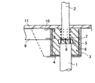
本発明に係る杭1と柱2との接合構造の第1実施例は、図1に示すように、基礎フーチング3において、前記杭(既製杭または現場打ち杭)1の頭部と、柱2の柱脚部とが当該基礎フーチング3内部に突出され、打設されたコンクリート4で一体化されていることである。杭頭には、補強筋6を有したコンクリート製のベース5が建方の治具として設けられ、この上にベースプレート7を介して柱2がアンカーボルト8で建方される。この基礎フーチング3に基礎梁9が設けられる場合には、アンカー筋10が配設されてコンクリートが打設される。この基礎梁は9、長期応力を負担させるようにする。符号11は、土間コンクリートを示している。
As shown in FIG. 1, the first embodiment of the joint structure between the
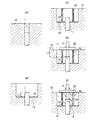
この杭1と柱2との接合工法は、図2(A)に示すように、地盤12に杭(以下、既製杭で説明する)1を貫入させる。同図(B)に示すように、根切りを行い、杭頭を根切り
底13から、約L1(杭1の径と同じ程度)の高さになるようにして突出させる。そして、根切り底13に捨てコンクリート14を打設する。
As shown in FIG. 2 (A), the
同図(C)に示すように、杭頭に、補強筋6とアンカーボルト8を配筋して、コンクリートを打設してベース5を形成する。このベース5の位置は、同図(D)に示すように、土間コンクリート11の上面からL2(柱2の径の約1.5倍)の位置となるように、形成する。
As shown in FIG. 3C, reinforcing
前記ベース5に柱2を建方し、ベースプレート7を介してボルトで締結してアンカーボルト8で固定する。次に、同図(E)に示すように、主筋・フープ筋を配筋して型枠16を形成し、該型枠16内部にコンクリートを打設して、円形若しくは矩形状の基礎フーチング3を形成する。このように、基礎フーチング3内に、杭頭と柱脚とを所定深さ埋設させて、杭1及び柱2を接合させた構造とするものである。
The
前記ベース5については、図3に示すように、例えば、予めベース5をPC化して形成しておき、ボルト17・ナット18でレベル調整しながら杭頭に取り付けることができる(同図(A))。これとは別に、杭頭に2枚の鉄板19をボルト20・ナット21とレベル調整ボルト22とで平行に配置し、SAP(サップ)アンカー23で柱2を建方するようにしても良い(同図(B))。
As shown in FIG. 3, for example, the
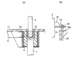
本発明の第2実施例は、図4に示すように、基礎フーチング3aが、所要の大きさで予め工場にて円形若しくは矩形状に形成されたプレキャスト型枠24と、該プレキャスト型枠24の内部に杭頭及び柱脚とを突設させて配設された杭1と柱2と、前記プレキャスト型枠24内に打設されたコンクリート4とから構成されているものである。
In the second embodiment of the present invention, as shown in FIG. 4, the
この接合工法は、図5(A),(B)に示すように、地盤12に杭1を貫入させ、そこを根切りして、その根切り底13から杭頭を前記第1実施例と同様にLIだけ突出させる。次に、捨てコンクリート14を打設する。そして、同図(C)に示すように、プレャスト型枠24をセットする。この場合、図では、余堀しているが、プレキャスト型枠24を設置するので、余堀をほとんど無くして施工することができる。それにより、工期が短縮され、産業廃棄物量も減少させることができる。
As shown in FIGS. 5 (A) and 5 (B), this joining method is made to penetrate the
次に、図5(D)に示すように、前記プレキャスト型枠24の上に、建方治具25をセットする。そして、柱2を建方する。基礎フーチングに対する埋め込み深さは、前記第1実施例と同様に、L2とする。同図(E)に示すように、前記プレキャスト型枠24の内部に、上からコンクリート4を打設する。これにより、基礎フーチング3aが完成する。
Next, as shown in FIG. 5D, a
また、図6に示すように、前記建方治具25の代わりに、プレキャスト型枠24に治具25aと、レベル調整ボルト26及びターンバックル27により、柱2の建方を管理するようにしても良い。
Further, as shown in FIG. 6, instead of the
更に、図7に示すように、接合工法の作業手順を変更したものとして、地盤12の根切り工事を施工した後に、先にプレキャスト型枠24を吊治具28によって捨てコンクリート14分を浮かせた状態でセットする。この根切り工事においては、プレキャスト型枠24を使用するので、余堀はほとんど無い。そして、杭頭をL1の高さに埋め込みさせて、杭1を打設する。前記プレキャスト型枠24が、根切りした周囲の土壁の崩落を防止するケーシングの作用をする。
Furthermore, as shown in FIG. 7, assuming that the work procedure of the joining method has been changed, after performing the root cutting work of the
更に、捨てコンクリート14を打設した後、前記吊治具28を撤去し、建方治具25をプレキャスト型枠24の上にセットする。そして、柱2を、その柱脚をL2にして建方する。プレキャスト型枠24の内部にコンクリートを打設して基礎フーチング3を形成する。この後、前記建方治具25を撤去して、地盤12の上に土間コンクリート11を打設する。
Further, after placing the discarded
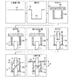
本発明の第3実施例は、図8に示すように、柱2の建方において、柱支持方法を変えた例である。即ち、前記実施例と同様に、地盤12に杭1を打設した後に、図9(A)に示すように、杭頭の周囲に主筋・フープ筋を配筋して、捨てコンクリート14の上に型枠16をセットする。この型枠16の中に、図示する位置までコンクリートを打設する。
As shown in FIG. 8, the third embodiment of the present invention is an example in which the pillar support method is changed in the construction of the
次に、図9(B)に示すように、アンカー鉄筋29及びベースプレート29aを配設して、型枠16aをセットし、コンクリートを打設する。前記型枠16,16aを撤去した後に、図8(B)と図9(C)に示すように、前記ベースプレート29aにSAPアンカー30を立設し、柱2に固着させた建方治具33のフランジ部をレベル調整ナット31で高さと水平を調整し、固定ナット32で固定する。その後、柱脚の部分にコンクリートを打設して、基礎フーチング3を形成する。そして、図8(A)に示すように、土間コンクリート11を打設する。前記建方治具33はこの前記土間コンクリート11に埋め殺しする。
Next, as shown in FIG. 9B, the
この第3実施例の他の方法として、図10に示すように、プレキャスト型枠24aを使用するものがある。これにより、前記図9(A),(B)の工程を省いて、杭1を打設して捨てコンクリートを打設した後に、図9(C)の工程になり、柱2の建方をした後、内部にコンクリートを打設することで基礎フーチング3が形成される。工期が短縮されると共に、余堀も少なく産業廃棄物の発生を抑制できる。
As another method of the third embodiment, there is a method using a
1 杭、
2 柱、
3,3a 基礎フーチング、
4 コンクリート、
5 ベース、
6 補強筋、
7 ベースプレート、
8 アンカーボルト、
9 基礎梁、
10 アンカー筋、
11 土間コンクリート、
12 地盤、
13 根切り底、
14 捨てコンクリート、
16,16a 型枠、
17 ボルト、
18 ナット、
19 鉄板、
20 ボルト、
21 ネット、
22 レベル調整ボルト、
23 SAPアンカー、
24,24a プレキャスト型枠、
25 建方治具、 25a 治具、
26 レベル調整ボルト、
27 ターンバックル、
28 吊治具、
29 アンカー鉄筋、
30 SAPアンカー、
31 レベル調整ナット、
32 固定ナット、
33 建方治具。
1 pile,
2 pillars,
3, 3a Basic footing,
4 Concrete,
5 base,
6 Reinforcing bars,
7 Base plate,
8 Anchor bolt,
9 Foundation beams,
10 anchor muscles,
11 Dust concrete,
12 Ground,
13 Root cutting bottom,
14 Abandoned concrete,
16, 16a formwork,
17 volts,
18 nuts,
19 Iron plate,
20 volts,
21 Net
22 level adjustment bolts,
23 SAP anchor,
24, 24a precast formwork,
25 construction jig, 25a jig,
26 level adjustment bolts,
27 Turnbuckle,
28 Suspension jig,
29 Anchor rebar,
30 SAP anchor,
31 level adjustment nut,
32 fixing nuts,
33 Construction jig.
Claims (5)
特徴とする杭と柱との接合工法。 After constructing the pile and cutting the ground, set the column construction jig prior to the foundation construction, build the column, and base the pile head of the pile and the column base of the column In a state of projecting into the footing, install the formwork for the foundation footing, place concrete in the interior space of the formwork, and bury the pile head and column base in the foundation footing to Joining the pillars,
A characteristic method of joining the pile and column.
特徴とする杭と柱との接合工法。 After construction of piles and root cutting, a precast formwork for foundation footing is installed prior to foundation construction, and a column construction jig is set on the precast formwork. The pile head of the pile and the column base of the column are made to project into the precast formwork, and concrete is placed in the space inside the precast formwork. Burying the legs and joining the piles and columns;
A characteristic method of joining the pile and column.
特徴とする請求項1に記載の杭と柱との接合工法。 The construction jig is a level adjustable jig provided on the pile head, or a level adjustable jig set on the formwork,
The method of joining a pile and a column according to claim 1, wherein the method is a joint method.
を特徴とする杭と柱との接合構造。 In the joint structure between a pile and a column, the foundation footing includes a pile head of the pile projecting inside the foundation footing and a column base of the column, and concrete placed inside the form for the foundation footing. It is integrated with
This is a joint structure between a pile and a column characterized by
を特徴とする杭と柱との接合構造。 In the joint structure between the pile and the column, the foundation footing is placed in the precast formwork, the pile head protruding from the precast formwork, the column base of the pillar, and the precast formwork. Composed of concrete made of,
This is a joint structure between a pile and a column characterized by
Priority Applications (1)
| Application Number | Priority Date | Filing Date | Title |
|---|---|---|---|
| JP2005021228A JP2006207265A (en) | 2005-01-28 | 2005-01-28 | Pile-column connection method and its structure |
Applications Claiming Priority (1)
| Application Number | Priority Date | Filing Date | Title |
|---|---|---|---|
| JP2005021228A JP2006207265A (en) | 2005-01-28 | 2005-01-28 | Pile-column connection method and its structure |
Publications (1)
| Publication Number | Publication Date |
|---|---|
| JP2006207265A true JP2006207265A (en) | 2006-08-10 |
Family
ID=36964418
Family Applications (1)
| Application Number | Title | Priority Date | Filing Date |
|---|---|---|---|
| JP2005021228A Pending JP2006207265A (en) | 2005-01-28 | 2005-01-28 | Pile-column connection method and its structure |
Country Status (1)
| Country | Link |
|---|---|
| JP (1) | JP2006207265A (en) |
Cited By (7)
| Publication number | Priority date | Publication date | Assignee | Title |
|---|---|---|---|---|
| KR100943062B1 (en) | 2009-06-10 | 2010-02-17 | (주)세림철탑산업 | The basis structure of steel pipe and method |
| JP2012057430A (en) * | 2010-09-13 | 2012-03-22 | Sumitomo Mitsui Construction Co Ltd | Structure and method for connecting pile and steel column |
| CN102494776A (en) * | 2007-04-03 | 2012-06-13 | 武藤工业株式会社 | Spectrophotometer and method |
| JP2016104946A (en) * | 2014-12-01 | 2016-06-09 | 株式会社竹中工務店 | Foundation section construction method |
| JP2016156145A (en) * | 2015-02-23 | 2016-09-01 | 株式会社竹中工務店 | Foundation construction method |
| JP2020094421A (en) * | 2018-12-13 | 2020-06-18 | Jfeシビル株式会社 | Joint structure for pile and superstructure, construction method for joint structure, and structural body |
| JP2021161820A (en) * | 2020-04-02 | 2021-10-11 | ジオスター株式会社 | Half-precast structure tide embankment and method for constructing the same |
-
2005
- 2005-01-28 JP JP2005021228A patent/JP2006207265A/en active Pending
Cited By (11)
| Publication number | Priority date | Publication date | Assignee | Title |
|---|---|---|---|---|
| CN102494776A (en) * | 2007-04-03 | 2012-06-13 | 武藤工业株式会社 | Spectrophotometer and method |
| CN102494776B (en) * | 2007-04-03 | 2014-11-19 | 武藤工业株式会社 | Spectrophotometer and method |
| KR100943062B1 (en) | 2009-06-10 | 2010-02-17 | (주)세림철탑산업 | The basis structure of steel pipe and method |
| JP2012057430A (en) * | 2010-09-13 | 2012-03-22 | Sumitomo Mitsui Construction Co Ltd | Structure and method for connecting pile and steel column |
| JP2016104946A (en) * | 2014-12-01 | 2016-06-09 | 株式会社竹中工務店 | Foundation section construction method |
| JP2016156145A (en) * | 2015-02-23 | 2016-09-01 | 株式会社竹中工務店 | Foundation construction method |
| JP2020094421A (en) * | 2018-12-13 | 2020-06-18 | Jfeシビル株式会社 | Joint structure for pile and superstructure, construction method for joint structure, and structural body |
| JP7146607B2 (en) | 2018-12-13 | 2022-10-04 | Jfeシビル株式会社 | Joint structure between pile and superstructure, construction method for joint structure, and structure |
| JP2021161820A (en) * | 2020-04-02 | 2021-10-11 | ジオスター株式会社 | Half-precast structure tide embankment and method for constructing the same |
| JP7518341B2 (en) | 2020-04-02 | 2024-07-18 | ジオスター株式会社 | Half-precast structure seawall and its construction method |
| JP7633581B2 (en) | 2020-04-02 | 2025-02-20 | ジオスター株式会社 | Half-precast structure seawall and its construction method |
Similar Documents
| Publication | Publication Date | Title |
|---|---|---|
| JP2002256573A (en) | Existing foundation reinforced steel tower foundation and its construction method | |
| JP6924682B2 (en) | Pile head seismic isolation structure and its construction method | |
| JP4069509B2 (en) | Construction method of reverse struts in the outer periphery of underground excavation space | |
| JP2006207265A (en) | Pile-column connection method and its structure | |
| JP2020197015A (en) | Construction method of foundation | |
| JP3671344B2 (en) | Joint structure between foundation pile and column base and its construction method | |
| JP3107716B2 (en) | Soil retaining wall | |
| JP3760304B2 (en) | Building foundation construction method | |
| JP4611113B2 (en) | Integrated construction method of pile and column | |
| JP5828986B1 (en) | PC formwork material and foundation construction method using the same | |
| KR100673475B1 (en) | PC girder member for base frame frame, assembly structure and method of construction | |
| JPS63280153A (en) | Reverse construction method for underground framework | |
| JP7112939B2 (en) | Joint structure between pile and foundation concrete, precast concrete body, and construction method | |
| JP3790310B2 (en) | Construction method of the building by the prior construction of steel frame | |
| JPH0517955A (en) | Execution method for direct foundation and form panel for direct foundation | |
| JP4332651B2 (en) | Foundation reinforcement device and foundation construction method | |
| JPH09151463A (en) | Column-integrated column base anchoring foundation structire and work execution method therefor | |
| JP4449595B2 (en) | Column-beam joint structure, method for constructing column-beam joint structure, method for constructing underground structure, and building | |
| JPH0841897A (en) | Foundation for building and construction method therefor | |
| JP2005240430A (en) | Building foundation and construction method | |
| JP2002115324A (en) | Column base unit, column integrated column base fixing foundation structure using the column base unit, and construction method therefor | |
| JP3658336B2 (en) | Independent foundation and its construction method and independent foundation | |
| KR101050271B1 (en) | Basic construction work method | |
| JPS6290445A (en) | Block for foundation and its manufacture | |
| JPH08291526A (en) | How to build an underground structure |