JP2006194440A - Compression-evaporating system for liquefied gas - Google Patents
Compression-evaporating system for liquefied gas Download PDFInfo
- Publication number
- JP2006194440A JP2006194440A JP2005363437A JP2005363437A JP2006194440A JP 2006194440 A JP2006194440 A JP 2006194440A JP 2005363437 A JP2005363437 A JP 2005363437A JP 2005363437 A JP2005363437 A JP 2005363437A JP 2006194440 A JP2006194440 A JP 2006194440A
- Authority
- JP
- Japan
- Prior art keywords
- pump
- motor
- motor driven
- driven turbo
- turbine
- Prior art date
- Legal status (The legal status is an assumption and is not a legal conclusion. Google has not performed a legal analysis and makes no representation as to the accuracy of the status listed.)
- Ceased
Links
- 238000001704 evaporation Methods 0.000 title claims abstract description 11
- 239000012530 fluid Substances 0.000 claims abstract description 73
- 230000008020 evaporation Effects 0.000 claims abstract description 7
- 230000003750 conditioning effect Effects 0.000 claims abstract description 5
- 239000007789 gas Substances 0.000 claims description 81
- 239000007788 liquid Substances 0.000 claims description 47
- 239000003949 liquefied natural gas Substances 0.000 claims description 31
- XLYOFNOQVPJJNP-UHFFFAOYSA-N water Substances O XLYOFNOQVPJJNP-UHFFFAOYSA-N 0.000 claims description 28
- 238000005086 pumping Methods 0.000 claims description 11
- 230000005284 excitation Effects 0.000 claims description 10
- 238000005452 bending Methods 0.000 claims description 6
- 229910001148 Al-Li alloy Inorganic materials 0.000 claims description 5
- 229910001069 Ti alloy Inorganic materials 0.000 claims description 5
- JFBZPFYRPYOZCQ-UHFFFAOYSA-N [Li].[Al] Chemical compound [Li].[Al] JFBZPFYRPYOZCQ-UHFFFAOYSA-N 0.000 claims description 5
- 238000007599 discharging Methods 0.000 claims description 5
- 229910001234 light alloy Inorganic materials 0.000 claims description 5
- 230000003068 static effect Effects 0.000 claims description 5
- 238000000605 extraction Methods 0.000 claims description 4
- 230000002706 hydrostatic effect Effects 0.000 claims description 4
- 230000001360 synchronised effect Effects 0.000 claims description 3
- 239000000919 ceramic Substances 0.000 claims description 2
- VNWKTOKETHGBQD-UHFFFAOYSA-N methane Chemical compound C VNWKTOKETHGBQD-UHFFFAOYSA-N 0.000 description 28
- 238000011084 recovery Methods 0.000 description 18
- 238000001816 cooling Methods 0.000 description 14
- 239000003345 natural gas Substances 0.000 description 11
- 238000000034 method Methods 0.000 description 8
- 238000011144 upstream manufacturing Methods 0.000 description 8
- 238000002955 isolation Methods 0.000 description 7
- 238000010586 diagram Methods 0.000 description 6
- 230000005611 electricity Effects 0.000 description 6
- 238000010438 heat treatment Methods 0.000 description 6
- 230000001105 regulatory effect Effects 0.000 description 6
- 238000004519 manufacturing process Methods 0.000 description 4
- 239000012071 phase Substances 0.000 description 4
- 230000001276 controlling effect Effects 0.000 description 3
- 238000005516 engineering process Methods 0.000 description 3
- 238000007667 floating Methods 0.000 description 3
- 239000013535 sea water Substances 0.000 description 3
- 238000003860 storage Methods 0.000 description 3
- 230000001052 transient effect Effects 0.000 description 3
- 230000004888 barrier function Effects 0.000 description 2
- 239000012809 cooling fluid Substances 0.000 description 2
- 238000009413 insulation Methods 0.000 description 2
- 230000004048 modification Effects 0.000 description 2
- 238000012986 modification Methods 0.000 description 2
- 238000010926 purge Methods 0.000 description 2
- 238000007789 sealing Methods 0.000 description 2
- 229910000831 Steel Inorganic materials 0.000 description 1
- 229910045601 alloy Inorganic materials 0.000 description 1
- 239000000956 alloy Substances 0.000 description 1
- 230000002051 biphasic effect Effects 0.000 description 1
- 230000008859 change Effects 0.000 description 1
- 239000011248 coating agent Substances 0.000 description 1
- 238000000576 coating method Methods 0.000 description 1
- 238000002485 combustion reaction Methods 0.000 description 1
- 238000007906 compression Methods 0.000 description 1
- 230000006835 compression Effects 0.000 description 1
- 230000001143 conditioned effect Effects 0.000 description 1
- 230000001627 detrimental effect Effects 0.000 description 1
- 238000009826 distribution Methods 0.000 description 1
- 230000001747 exhibiting effect Effects 0.000 description 1
- 238000011049 filling Methods 0.000 description 1
- 239000007791 liquid phase Substances 0.000 description 1
- 238000010943 off-gassing Methods 0.000 description 1
- 230000002093 peripheral effect Effects 0.000 description 1
- 230000008569 process Effects 0.000 description 1
- 230000002441 reversible effect Effects 0.000 description 1
- 239000010959 steel Substances 0.000 description 1
- 230000001502 supplementing effect Effects 0.000 description 1
Images


Classifications
-
- F—MECHANICAL ENGINEERING; LIGHTING; HEATING; WEAPONS; BLASTING
- F17—STORING OR DISTRIBUTING GASES OR LIQUIDS
- F17C—VESSELS FOR CONTAINING OR STORING COMPRESSED, LIQUEFIED OR SOLIDIFIED GASES; FIXED-CAPACITY GAS-HOLDERS; FILLING VESSELS WITH, OR DISCHARGING FROM VESSELS, COMPRESSED, LIQUEFIED, OR SOLIDIFIED GASES
- F17C7/00—Methods or apparatus for discharging liquefied, solidified, or compressed gases from pressure vessels, not covered by another subclass
- F17C7/02—Discharging liquefied gases
- F17C7/04—Discharging liquefied gases with change of state, e.g. vaporisation
-
- F—MECHANICAL ENGINEERING; LIGHTING; HEATING; WEAPONS; BLASTING
- F17—STORING OR DISTRIBUTING GASES OR LIQUIDS
- F17D—PIPE-LINE SYSTEMS; PIPE-LINES
- F17D1/00—Pipe-line systems
- F17D1/02—Pipe-line systems for gases or vapours
-
- F—MECHANICAL ENGINEERING; LIGHTING; HEATING; WEAPONS; BLASTING
- F17—STORING OR DISTRIBUTING GASES OR LIQUIDS
- F17C—VESSELS FOR CONTAINING OR STORING COMPRESSED, LIQUEFIED OR SOLIDIFIED GASES; FIXED-CAPACITY GAS-HOLDERS; FILLING VESSELS WITH, OR DISCHARGING FROM VESSELS, COMPRESSED, LIQUEFIED, OR SOLIDIFIED GASES
- F17C2221/00—Handled fluid, in particular type of fluid
- F17C2221/03—Mixtures
- F17C2221/032—Hydrocarbons
- F17C2221/033—Methane, e.g. natural gas, CNG, LNG, GNL, GNC, PLNG
-
- F—MECHANICAL ENGINEERING; LIGHTING; HEATING; WEAPONS; BLASTING
- F17—STORING OR DISTRIBUTING GASES OR LIQUIDS
- F17C—VESSELS FOR CONTAINING OR STORING COMPRESSED, LIQUEFIED OR SOLIDIFIED GASES; FIXED-CAPACITY GAS-HOLDERS; FILLING VESSELS WITH, OR DISCHARGING FROM VESSELS, COMPRESSED, LIQUEFIED, OR SOLIDIFIED GASES
- F17C2223/00—Handled fluid before transfer, i.e. state of fluid when stored in the vessel or before transfer from the vessel
- F17C2223/01—Handled fluid before transfer, i.e. state of fluid when stored in the vessel or before transfer from the vessel characterised by the phase
- F17C2223/0146—Two-phase
- F17C2223/0153—Liquefied gas, e.g. LPG, GPL
- F17C2223/0161—Liquefied gas, e.g. LPG, GPL cryogenic, e.g. LNG, GNL, PLNG
-
- F—MECHANICAL ENGINEERING; LIGHTING; HEATING; WEAPONS; BLASTING
- F17—STORING OR DISTRIBUTING GASES OR LIQUIDS
- F17C—VESSELS FOR CONTAINING OR STORING COMPRESSED, LIQUEFIED OR SOLIDIFIED GASES; FIXED-CAPACITY GAS-HOLDERS; FILLING VESSELS WITH, OR DISCHARGING FROM VESSELS, COMPRESSED, LIQUEFIED, OR SOLIDIFIED GASES
- F17C2223/00—Handled fluid before transfer, i.e. state of fluid when stored in the vessel or before transfer from the vessel
- F17C2223/03—Handled fluid before transfer, i.e. state of fluid when stored in the vessel or before transfer from the vessel characterised by the pressure level
- F17C2223/033—Small pressure, e.g. for liquefied gas
-
- F—MECHANICAL ENGINEERING; LIGHTING; HEATING; WEAPONS; BLASTING
- F17—STORING OR DISTRIBUTING GASES OR LIQUIDS
- F17C—VESSELS FOR CONTAINING OR STORING COMPRESSED, LIQUEFIED OR SOLIDIFIED GASES; FIXED-CAPACITY GAS-HOLDERS; FILLING VESSELS WITH, OR DISCHARGING FROM VESSELS, COMPRESSED, LIQUEFIED, OR SOLIDIFIED GASES
- F17C2225/00—Handled fluid after transfer, i.e. state of fluid after transfer from the vessel
- F17C2225/01—Handled fluid after transfer, i.e. state of fluid after transfer from the vessel characterised by the phase
- F17C2225/0107—Single phase
- F17C2225/0123—Single phase gaseous, e.g. CNG, GNC
-
- F—MECHANICAL ENGINEERING; LIGHTING; HEATING; WEAPONS; BLASTING
- F17—STORING OR DISTRIBUTING GASES OR LIQUIDS
- F17C—VESSELS FOR CONTAINING OR STORING COMPRESSED, LIQUEFIED OR SOLIDIFIED GASES; FIXED-CAPACITY GAS-HOLDERS; FILLING VESSELS WITH, OR DISCHARGING FROM VESSELS, COMPRESSED, LIQUEFIED, OR SOLIDIFIED GASES
- F17C2225/00—Handled fluid after transfer, i.e. state of fluid after transfer from the vessel
- F17C2225/03—Handled fluid after transfer, i.e. state of fluid after transfer from the vessel characterised by the pressure level
- F17C2225/036—Very high pressure, i.e. above 80 bars
-
- F—MECHANICAL ENGINEERING; LIGHTING; HEATING; WEAPONS; BLASTING
- F17—STORING OR DISTRIBUTING GASES OR LIQUIDS
- F17C—VESSELS FOR CONTAINING OR STORING COMPRESSED, LIQUEFIED OR SOLIDIFIED GASES; FIXED-CAPACITY GAS-HOLDERS; FILLING VESSELS WITH, OR DISCHARGING FROM VESSELS, COMPRESSED, LIQUEFIED, OR SOLIDIFIED GASES
- F17C2227/00—Transfer of fluids, i.e. method or means for transferring the fluid; Heat exchange with the fluid
- F17C2227/01—Propulsion of the fluid
- F17C2227/0128—Propulsion of the fluid with pumps or compressors
- F17C2227/0135—Pumps
- F17C2227/0142—Pumps with specified pump type, e.g. piston or impulsive type
-
- F—MECHANICAL ENGINEERING; LIGHTING; HEATING; WEAPONS; BLASTING
- F17—STORING OR DISTRIBUTING GASES OR LIQUIDS
- F17C—VESSELS FOR CONTAINING OR STORING COMPRESSED, LIQUEFIED OR SOLIDIFIED GASES; FIXED-CAPACITY GAS-HOLDERS; FILLING VESSELS WITH, OR DISCHARGING FROM VESSELS, COMPRESSED, LIQUEFIED, OR SOLIDIFIED GASES
- F17C2227/00—Transfer of fluids, i.e. method or means for transferring the fluid; Heat exchange with the fluid
- F17C2227/01—Propulsion of the fluid
- F17C2227/0128—Propulsion of the fluid with pumps or compressors
- F17C2227/0157—Compressors
-
- F—MECHANICAL ENGINEERING; LIGHTING; HEATING; WEAPONS; BLASTING
- F17—STORING OR DISTRIBUTING GASES OR LIQUIDS
- F17C—VESSELS FOR CONTAINING OR STORING COMPRESSED, LIQUEFIED OR SOLIDIFIED GASES; FIXED-CAPACITY GAS-HOLDERS; FILLING VESSELS WITH, OR DISCHARGING FROM VESSELS, COMPRESSED, LIQUEFIED, OR SOLIDIFIED GASES
- F17C2227/00—Transfer of fluids, i.e. method or means for transferring the fluid; Heat exchange with the fluid
- F17C2227/03—Heat exchange with the fluid
- F17C2227/0302—Heat exchange with the fluid by heating
- F17C2227/0309—Heat exchange with the fluid by heating using another fluid
- F17C2227/0316—Water heating
-
- F—MECHANICAL ENGINEERING; LIGHTING; HEATING; WEAPONS; BLASTING
- F17—STORING OR DISTRIBUTING GASES OR LIQUIDS
- F17C—VESSELS FOR CONTAINING OR STORING COMPRESSED, LIQUEFIED OR SOLIDIFIED GASES; FIXED-CAPACITY GAS-HOLDERS; FILLING VESSELS WITH, OR DISCHARGING FROM VESSELS, COMPRESSED, LIQUEFIED, OR SOLIDIFIED GASES
- F17C2227/00—Transfer of fluids, i.e. method or means for transferring the fluid; Heat exchange with the fluid
- F17C2227/03—Heat exchange with the fluid
- F17C2227/0367—Localisation of heat exchange
- F17C2227/0388—Localisation of heat exchange separate
- F17C2227/0393—Localisation of heat exchange separate using a vaporiser
-
- F—MECHANICAL ENGINEERING; LIGHTING; HEATING; WEAPONS; BLASTING
- F17—STORING OR DISTRIBUTING GASES OR LIQUIDS
- F17C—VESSELS FOR CONTAINING OR STORING COMPRESSED, LIQUEFIED OR SOLIDIFIED GASES; FIXED-CAPACITY GAS-HOLDERS; FILLING VESSELS WITH, OR DISCHARGING FROM VESSELS, COMPRESSED, LIQUEFIED, OR SOLIDIFIED GASES
- F17C2260/00—Purposes of gas storage and gas handling
- F17C2260/04—Reducing risks and environmental impact
- F17C2260/046—Enhancing energy recovery
-
- F—MECHANICAL ENGINEERING; LIGHTING; HEATING; WEAPONS; BLASTING
- F17—STORING OR DISTRIBUTING GASES OR LIQUIDS
- F17C—VESSELS FOR CONTAINING OR STORING COMPRESSED, LIQUEFIED OR SOLIDIFIED GASES; FIXED-CAPACITY GAS-HOLDERS; FILLING VESSELS WITH, OR DISCHARGING FROM VESSELS, COMPRESSED, LIQUEFIED, OR SOLIDIFIED GASES
- F17C2265/00—Effects achieved by gas storage or gas handling
- F17C2265/05—Regasification
-
- F—MECHANICAL ENGINEERING; LIGHTING; HEATING; WEAPONS; BLASTING
- F17—STORING OR DISTRIBUTING GASES OR LIQUIDS
- F17C—VESSELS FOR CONTAINING OR STORING COMPRESSED, LIQUEFIED OR SOLIDIFIED GASES; FIXED-CAPACITY GAS-HOLDERS; FILLING VESSELS WITH, OR DISCHARGING FROM VESSELS, COMPRESSED, LIQUEFIED, OR SOLIDIFIED GASES
- F17C2265/00—Effects achieved by gas storage or gas handling
- F17C2265/06—Fluid distribution
- F17C2265/068—Distribution pipeline networks
-
- F—MECHANICAL ENGINEERING; LIGHTING; HEATING; WEAPONS; BLASTING
- F17—STORING OR DISTRIBUTING GASES OR LIQUIDS
- F17C—VESSELS FOR CONTAINING OR STORING COMPRESSED, LIQUEFIED OR SOLIDIFIED GASES; FIXED-CAPACITY GAS-HOLDERS; FILLING VESSELS WITH, OR DISCHARGING FROM VESSELS, COMPRESSED, LIQUEFIED, OR SOLIDIFIED GASES
- F17C2270/00—Applications
- F17C2270/01—Applications for fluid transport or storage
- F17C2270/0134—Applications for fluid transport or storage placed above the ground
- F17C2270/0136—Terminals
-
- Y—GENERAL TAGGING OF NEW TECHNOLOGICAL DEVELOPMENTS; GENERAL TAGGING OF CROSS-SECTIONAL TECHNOLOGIES SPANNING OVER SEVERAL SECTIONS OF THE IPC; TECHNICAL SUBJECTS COVERED BY FORMER USPC CROSS-REFERENCE ART COLLECTIONS [XRACs] AND DIGESTS
- Y02—TECHNOLOGIES OR APPLICATIONS FOR MITIGATION OR ADAPTATION AGAINST CLIMATE CHANGE
- Y02E—REDUCTION OF GREENHOUSE GAS [GHG] EMISSIONS, RELATED TO ENERGY GENERATION, TRANSMISSION OR DISTRIBUTION
- Y02E20/00—Combustion technologies with mitigation potential
- Y02E20/14—Combined heat and power generation [CHP]
Abstract
Description
本発明は、タンクに収容される液化ガス用の圧縮器−蒸発器システムであって、液化ガスをタンク外部へ低圧下にて抜き出しおよび送給するための抜出しおよびポンプ手段、高圧ポンプ手段、液体との熱交換により動作する蒸発器手段、ならびにガスをコンディショニングおよびガスパイプラインに移送するための手段を含んで成るシステムに関する。 The present invention relates to a compressor-evaporator system for liquefied gas accommodated in a tank, and is a drawing and pumping means for extracting and feeding liquefied gas to the outside of the tank under low pressure, a high-pressure pump means, a liquid To a system comprising evaporator means operating by heat exchange with and a means for transferring gas to the conditioning and gas pipeline.
本発明は液化ガスを再びガス化する方法という一般的分野に関し、およびより詳細には、本発明は液化天然ガス(LNG)に関する。 The present invention relates to the general field of methods for regasifying liquefied gas and, more particularly, the invention relates to liquefied natural gas (LNG).
実際には、取り出した天然ガスの一部は、生産地とガスの消費地との間をタンカー船にて液体状態で運搬することが可能なように液化させている。従って、そのようなガス輸送システムには液化および貯蔵ターミナルが含まれ、そこからメタンタンカーが充填され、その後、消費地の陸上分配ネットワークにガスパイプラインを通じてガスを供給するために液化ガスを貯蔵し、加圧下に置き、そして蒸発させるためのターミナルへ液化ガスを運搬する。消費地のターミナルは再ガス化ターミナルと呼ばれる。 Actually, a part of the extracted natural gas is liquefied so that it can be transported in a liquid state between a production area and a gas consumption area by a tanker ship. Thus, such a gas transport system includes a liquefaction and storage terminal from which methane tankers are filled, and then stores the liquefied gas to supply gas through the gas pipeline to the terrestrial distribution network of the consuming area, Place the liquefied gas under pressure and to a terminal for evaporation. The terminal of consumption area is called the regasification terminal.
ターミナルの貯蔵タンクまたはタンカー船内にて元々平衡状態にあり、蒸気の圧力が大気圧よりわずかに高いLNGを加圧および周囲温度まで加熱するため、これまでの技術状態は、図10に示すように、まず、貯蔵タンク301に浸漬した低圧モーター駆動ポンプ302を用い、そしてバッファ容積307に浸漬した高圧モーター駆動ポンプ303に供給することにより構成されるものであった。高圧ポンプ303の出口にて液体を熱交換器かつ蒸発器304に送り、この熱交換器かつ蒸発器304は、気候条件が許せば豊富に利用可能な周囲温度の水(海水、河口水など)が供給され、あるいは熱水(これは特別な目的の燃焼によって、または近隣の発熱機械から損失熱を回収することによって得られる)が供給され、LNGをガスパイプライン400に投入するに先立って周囲温度にて高い圧力に上昇させるよう機能する。高圧ポンプ303を駆動するために使用するモーター305aは通常、非同期かご形モーターであり、次の所定の制限速度にて動作する:50ヘルツ(Hz)での三相交流(AC)の場合は最大3000回転毎分(rpm)、および60HzでのACの場合は3600rpm。この技術のため、ポンプ303はステージが多数になり、また寸法の大きなものとなった。特に、このような技術は海上用途に対して決定的に不利な条件となる。更に、高圧ポンプ303は大量の電気を必要とし、これはターミナルの運転費用のうち最も高額の財務経費になっている。
Since the LNG that was originally in equilibrium in the storage tank or tanker of the terminal and the vapor pressure is slightly higher than atmospheric pressure is heated to the pressurization and ambient temperature, the state of technology so far is as shown in FIG. First, the low pressure
図10は従来技術のメタンターミナルでの再ガス化法の原理を示す概略図である。このターミナルでは高圧ポンピング(またはポンプ移送)機能および加熱/蒸発機能が地理的にひとまとめにされ(または一緒にグループ化され)、また、移送ライン370、371および372の数は1つまたは2つに制限されている。この概略図では機能毎に1個の装置のみを示し、加えて、理解を容易にするためにバルブ、調整および制御装置は図示していない。3つのタイプのバルブのみを概略図に示す。バルブ3V1は高圧(HP)ポンプ303からの送給部に位置し、またバルブ3V2は排出部として機能するパイプライン400への入口に位置する。バルブ3V1および3V2はライン371および372を通るパイプライン400への流速および送給圧力を調節するのに寄与する。実際には、バルブ3V2は停止弁または逆止弁と直列になっている。最後に、バルブ3V3により、HPポンプ303を始動させるのに先立つ初期冷却のために、低圧のLNGをライン373に通じてタンク301または所定の回路に再循環させることができる。LNGを低圧(LP)モーター駆動ポンプ302によりタンク301から取り出し、そしてHPポンプ303の入口に送給し、その後、圧力下にてガスの形態でパイプラインネットワーク400に投入するに先立って熱交換器かつ蒸発器304に通す。蒸発器304には供給回路374を通じて水が供給され、そして排出回路375により排出される。
FIG. 10 is a schematic diagram showing the principle of a conventional regasification method at a methane terminal. In this terminal, high pressure pumping (or pumping) functions and heating / evaporation functions are geographically grouped (or grouped together), and the number of
工業的プロセスにて加熱する必要のある極めて低い温度の冷源(cold source:または低温源)が存在することは価値を得る機会となり、数多くの利用が従来の刊行物または特許に記載または提案されている。一例として、ターミナルに冷却設備または工業ガスの液化設備を組み合わせたものを挙げることができる。低温LNGの考えられる全ての利用のうち、本願説明はターミナルにて直接使用できるエネルギーを回収するために圧縮ならびに加熱および蒸発方法を適用した解決策に限るものである。 The presence of a very low temperature cold source that needs to be heated in an industrial process presents an opportunity to gain value, and numerous uses have been described or suggested in conventional publications or patents. ing. As an example, a terminal combined with cooling equipment or industrial gas liquefaction equipment can be mentioned. Of all possible uses of low temperature LNG, the description is limited to solutions that apply compression and heating and evaporation methods to recover energy that can be used directly at the terminal.
この方法の熱力学的な面を検討すると、この方法はまずポンプによりLNGの圧力を上昇させ、次に熱交換器かつ蒸発器によりLNGの温度およびエンタルピーを増加させることから構成されるものであるが、エネルギーを回収するために2つの可能なスキーム(または方策)が存在すると認められる。 Examining the thermodynamic aspects of this method, it consists of first increasing the LNG pressure with a pump and then increasing the LNG temperature and enthalpy with a heat exchanger and evaporator. However, it is recognized that there are two possible schemes (or strategies) for recovering energy.
第1のスキームは、ポンピングの間、液化天然ガスの圧力を必要な圧力より高い圧力に上昇させ、その後、流体エネルギーを機械的エネルギーに変換するよう働くタービンに通じてガスパイプラインの圧力にまで下げて膨張させることより構成される。よって、ガスを膨張させることによりタービンで回収されるエンタルピーはポンピングのために供給する必要のある追加のエネルギーよりも大きいので、エネルギー収支はプラスになる。 The first scheme raises the pressure of liquefied natural gas during pumping to a pressure higher than necessary and then lowers it to the pressure of the gas pipeline through a turbine that serves to convert fluid energy into mechanical energy. And inflating. Thus, the energy balance is positive because the enthalpy recovered in the turbine by expanding the gas is greater than the additional energy that needs to be supplied for pumping.
第2のスキームは液化天然ガスを周囲温度またはより高い温度にある熱源を用いる熱力学的サイクルにおいて冷源として用いることにより構成される。 The second scheme consists of using liquefied natural gas as a cold source in a thermodynamic cycle using a heat source at ambient or higher temperatures.
それら様々なエネルギー回収原理は、例えば次の特許文献などの過去の数々の特許または文書の主題を成すものである:米国特許第2 937 504号、米国特許第3 068 659号、仏国特許第2 133 683号、スイス特許第569 865号、仏国特許第2 300 216号、仏国特許第2 318 590号、米国特許第4 444 015号、欧州特許第0 470 532号、およびまたJ. Ribesse(ディストリガス(Distrigaz)、ベルギー)による「液化天然ガスに含まれるフリゴリー(frigorie:または冷却熱量)を回収するためのサイクル」と題された文献XP−003 079414(1981年)。 These various energy recovery principles are the subject of a number of past patents or documents, for example the following patent documents: US Pat. No. 2,937,504, US Pat. No. 3,068,659, French Patent No. No. 2 133 683, Swiss Patent No. 569 865, French Patent No. 2 300 216, French Patent No. 2 318 590, US Pat. No. 4,444,015, European Patent No. 0 470 532, and also J. Pat. Document XP-003 079414 (1981) entitled "Cycle for recovering frigory (or cooling heat) contained in liquefied natural gas" by Ribesse (Distrigaz, Belgium).
これら文献は本質的にエネルギー回収サイクルの原理を記載しようとするものであり、そして一般的にこれらは具体的な適用を成すことのできる実施例を提示していない。 These documents are essentially intended to describe the principles of the energy recovery cycle, and in general they do not present examples that can make specific applications.
米国特許第5 678 411号にはより厳密に適用したものが記載され、このデバイスで使用されるターボポンプは天然ガス蒸発を海水が供給される熱交換器にて実施し、タービンは熱交換器により蒸発したガスの部分膨張からポンプに駆動力を供給する。しかしながら、気体のエンタルピーでは3メガパスカル(MPa)〜6MPaの出口圧力を得るのに十分な程度でしかない。この圧力は多数のガスパイプライン、および特に供給圧力が8MPaに近く、用途によっては10MPaに達することのある欧州ネットワークには低すぎる。このことは、4.596MPaおよび190.5ケルビン(K)の臨界点を有するメタンから本質的に構成されるという天然ガスの特性に起因するものである。15MPa、273Kおよび10MPa(よって、臨界点に近い)間での断熱膨張におけるエンタルピー差は、液体を0.5MPaから15MPaに圧縮するのに要する力より小さい。 US Pat. No. 5,678,411 describes a more rigorous application in which the turbopump used in this device performs natural gas evaporation in a heat exchanger fed with seawater and the turbine is a heat exchanger The driving force is supplied to the pump from the partial expansion of the gas evaporated by the above. However, the enthalpy of gas is only sufficient to obtain an outlet pressure of 3 megapascals (MPa) to 6 MPa. This pressure is too low for many gas pipelines and especially for European networks where the supply pressure is close to 8 MPa and in some applications can reach 10 MPa. This is due to the nature of natural gas consisting essentially of methane with critical points of 4.596 MPa and 190.5 Kelvin (K). The enthalpy difference in adiabatic expansion between 15 MPa, 273 K and 10 MPa (and thus near the critical point) is less than the force required to compress the liquid from 0.5 MPa to 15 MPa.
この問題を回避するため、米国特許第5 649 425号は、天然ガスおよび空気で動作するバーナーによって、タービンより上流の天然ガスを周囲温度より高い温度に加熱する。このような加熱により、より多くのエンタルピーをタービンで回収し、よってポンピングのエネルギーを補うことができるが、燃焼したガスや、また高圧ポンプに使用した電力で代表される経済的損失という犠牲を払うものである。この米国特許第5 649 425号は第2の解決策を提案している:ポンプを二段ポンプ(または2つのグループのステージを有するポンプ)とし、LNGの流れの全部を第1ポンプステージに通し、そして、主要な流れのフラクションをより高い圧力に上昇させ、その後、熱交換器にて加熱および蒸発させてタービンを駆動する。第1ステージからのLNGの流れは補助的な機能、例えば発電所への供給などに使用する。 To avoid this problem, US Pat. No. 5,649,425 heats natural gas upstream of the turbine to a temperature above ambient temperature by a burner operating with natural gas and air. Such heating allows more enthalpy to be recovered by the turbine, thus supplementing the energy of the pumping, but at the expense of economic losses typified by the burned gas and also the power used for the high pressure pump. Is. This US Pat. No. 5,649,425 proposes a second solution: the pump is a two-stage pump (or a pump with two groups of stages) and the entire LNG flow is passed through the first pump stage. The main flow fraction is then raised to a higher pressure and then heated and evaporated in a heat exchanger to drive the turbine. The LNG flow from the first stage is used for ancillary functions such as supply to the power plant.
この解決策は、ガスターミナルが発電所につながっていて、これにガスを2つの圧力レベルで供給できる場合にしか使用できない。 This solution can only be used if the gas terminal is connected to a power plant and can be supplied with gas at two pressure levels.
また、高圧ポンプには以下の不都合がある:
a)それらは比較的低速(3000rpm〜3600rpm)で回転する無調整かご形非同期モーターによって駆動し、およびそれらは必要な圧力上昇を実現するために多数のステージ(典型的には10〜20)を要する;
b)そのような多数の遠心ステージを有するポンプ構成は高価で重くて嵩張る大型の機械(典型的には6メートル(m)の高さ)をもたらし、また、必要が生じても、ガスパイプライン内の圧力上昇に耐えるのは比較的困難である;
c)それらはそのようなモーターの動力制限(1メガワット(MW)〜2MW)により流量が制限され、またそれらはターミナルからガスを必要な流量で送給するために並列に使用することを要する;および
d)それらのモーターは調整されず、そのガス流量は送給部出口に位置するスロットルバルブによってのみサーボ機構で制御でき、またその技術は電力消費の点で極めて不利である。
High pressure pumps also have the following disadvantages:
a) They are driven by an unregulated squirrel-cage asynchronous motor that rotates at a relatively low speed (3000-3600 rpm), and they use multiple stages (typically 10-20) to achieve the required pressure rise It takes;
b) A pump configuration with such a large number of centrifugal stages results in a large machine that is expensive, heavy and bulky (typically 6 meters (m) high) and, if necessary, within the gas pipeline It is relatively difficult to withstand the pressure increase of
c) They are limited in flow rate due to the power limitations of such motors (1 megawatt (MW) to 2 MW) and they need to be used in parallel to deliver gas from the terminal at the required flow rate; And d) the motors are not regulated and the gas flow rate can be controlled by the servomechanism only by means of a throttle valve located at the outlet of the feed section, and the technique is very disadvantageous in terms of power consumption.
本発明は、上述の不都合を軽減し、および再ガス化LNGターミナルの電力消費を低減し、または更にはなくすことを可能にするよう模索するものである。 The present invention seeks to alleviate the above-mentioned disadvantages and make it possible to reduce or even eliminate the power consumption of the regasification LNG terminal.
従って、本発明は既存のシステムに関する上述の不都合を軽減すると同時に、電力消費を低減し、または更にはなくすことを可能にし、あるいは場合により電気を生産するものとさえなり得る、再ガス化LNGターミナルについてのグローバルで、経済的に実行可能な解決策を提供することを模索するものである。また、本発明は熱機械を用いる発電所にターミナルが接続されている特定の構成に対しても首尾よく適用され、発電所からの損失熱を回収してターミナルの熱交換器かつ蒸発器に移送する。また、本発明は液化ガスを圧縮および周囲温度に加熱することを実施する任意の産業プロセスにも適用可能である。 Thus, the present invention alleviates the above disadvantages associated with existing systems, while at the same time reducing power consumption or even eliminating or possibly even producing electricity, a regasification LNG terminal. It seeks to provide a globally and economically viable solution. The present invention is also successfully applied to a specific configuration in which the terminal is connected to a power plant using a thermal machine, recovering the heat loss from the power plant and transferring it to the heat exchanger and evaporator of the terminal. To do. The invention is also applicable to any industrial process that implements compressing and heating liquefied gas to ambient temperature.
これらの目的は次の圧縮器−蒸発器システムにより達成される:タンクに収容される液化ガス用の圧縮器−蒸発器システムであって、このシステムは、液化ガスをタンク外部に低圧下にて抜き出しおよび送給するための抜出しおよびポンプ手段、高圧ポンプ手段、液体との熱交換により動作する蒸発器手段、ならびにガスをコンディショニングし(または適当な状態とし)およびガスパイプラインに移送するための手段を含み、システムは、軸方向吸引ステージおよび少なくとも1つの遠心ホイールを含む少なくとも1つの高圧ポンプ、タービン、ならびにモーターモードまたは発電機モードにて使用可能であり、および高圧ポンプとタービンとの間に位置する中央電気機械を有する、極めて高い曲げ剛性を有する回転アセンブリを共通軸線上に含んで成るモーター駆動ターボポンプより構成される少なくとも1つのターボ機械を含んで成り、該モーター駆動ターボポンプは周囲の媒体に対して静的シールのみを提供する堅いケーシング内にコンパクトに配置され、モーター駆動ターボポンプの回転アセンブリは回転危険速度の励振域外にとどまりながらも12,000rpm以上の高速回転を示すように適用され、モーター駆動ターボポンプの内側部分の全てがタンクに収容される液化ガスと同じ低温流体中に浸漬され、異なる熱力学的条件下にあるモーター駆動ターボポンプの内側空洞部が非接触動的シールにより隔てられ、および電気ネットワークに接続された電力回路(electronic power circuit)が中央電気機械をモーターモードまたは発電機モードに制御するように機能することを特徴とするシステム。 These objectives are achieved by the following compressor-evaporator system: a compressor-evaporator system for the liquefied gas contained in the tank, the liquefied gas being placed outside the tank under low pressure. Extraction and pumping means for extraction and delivery, high-pressure pumping means, evaporator means operating by heat exchange with liquid, and means for conditioning (or making it suitable) and transporting it to the gas pipeline The system is usable in at least one high pressure pump, turbine and motor mode or generator mode including an axial suction stage and at least one centrifugal wheel, and is located between the high pressure pump and the turbine Rotating assembly with very high bending stiffness with central electric machine on a common axis Comprising at least one turbomachine composed of a motor-driven turbopump comprising: the motor-driven turbopump disposed compactly in a rigid casing that provides only a static seal against surrounding media; The rotating assembly of the motor-driven turbo pump is applied to exhibit high speed rotation of 12,000 rpm or more while remaining outside the excitation range of the critical rotation speed, and all of the inner part of the motor-driven turbo pump is liquefied gas contained in the tank. A motor-driven turbopump's inner cavity immersed in the same cryogenic fluid and under different thermodynamic conditions is separated by a non-contact dynamic seal, and an electronic power circuit connected to the electrical network is central Function to control the electric machine in motor mode or generator mode System according to claim.
好都合には、モーター駆動ターボポンプの回転アセンブリの回転速度は数万回転毎分(rpm)であり、そして好ましくは20,000rpm〜40,000rpmの範囲にある。 Conveniently, the rotational speed of the rotating assembly of the motor driven turbo pump is tens of thousands of revolutions per minute (rpm) and is preferably in the range of 20,000 rpm to 40,000 rpm.
多様な態様が可能であり、詳細には、本発明に従って、モーター駆動ターボポンプはターミナルの送給ラインに直接に、または高圧ポンプからの出口と再ガス化熱交換器との間で並列に組み込まれ得る。 Various aspects are possible, in particular, according to the present invention, the motor driven turbo pump is incorporated directly into the terminal feed line or in parallel between the outlet from the high pressure pump and the regasification heat exchanger Can be.
好都合な特定の(または詳細な)態様において、システムはモーター駆動ターボポンプにて作動流体として使用される液化ガスを圧縮および蒸発させるために、高圧ポンプとタービンとの間に介挿された第1熱交換器かつ蒸発器を含んで成る。 In a convenient particular (or detailed) embodiment, the system includes a first interposed between the high pressure pump and the turbine to compress and evaporate the liquefied gas used as the working fluid in the motor driven turbo pump. A heat exchanger and an evaporator.
蒸発器手段は、高圧ポンプとタービンとの間に介挿された上記第1熱交換器かつ蒸発器、およびタービンと供給すべきパイプラインとの間に配置された第2熱交換器かつ蒸発器を含んでいてよい。 The evaporator means includes the first heat exchanger and the evaporator interposed between the high-pressure pump and the turbine, and the second heat exchanger and the evaporator disposed between the turbine and the pipeline to be supplied. May be included.
特定の態様において、高圧ポンプ手段は、タンクとパイプラインとの間で直列に接続されたモーター駆動ターボポンプの高圧ポンプのみを(またはこれ単独で)含んで成る。 In a particular embodiment, the high-pressure pump means comprises only (or alone) a motor-driven turbopump high-pressure pump connected in series between the tank and the pipeline.
システムは、モーター駆動ターボポンプの高圧ポンプへの入口に配置されたバッファ容積を含んでいてよい。 The system may include a buffer volume located at the inlet to the high pressure pump of the motor driven turbo pump.
特定の態様において、システムは、モーター駆動ターボポンプの高圧ポンプの出口と第1熱交換器かつ蒸発器との間に介挿された第1回路、およびモーター駆動ターボポンプのタービンの出口とバッファ容積との間に介挿された第2回路を有する凝縮器を更に含んで成り、第2回路は上記タービンを出たガスを再液化するように第1回路と熱交換する。 In certain aspects, the system includes a first circuit interposed between a high pressure pump outlet of a motor driven turbo pump and a first heat exchanger and an evaporator, and a turbine outlet and buffer volume of the motor driven turbo pump. And a condenser having a second circuit interposed therebetween, wherein the second circuit exchanges heat with the first circuit to reliquefy the gas exiting the turbine.
もう1つの特定の態様において、高圧ポンプ手段は、上記抜出しおよびポンプ手段と接続される入口を有し、および凝縮器の第1回路に接続される出口を有するモーター駆動ポンプを含んで成り、上記パイプラインに出口が接続される熱交換器かつ蒸発器の入口に該第1回路からの出口が接続され、上記バッファ容積が該モーター駆動ポンプの出口に接続される分岐接続部に存在し、ならびにモーター駆動ターボポンプのタービンからの出口が凝縮器の第2回路の入口に接続され、該第2回路からの出口が該バッファ容積に接続され、該第2回路は該タービンを出たガスを再液化するように第1回路と熱交換する。 In another particular embodiment, the high pressure pump means comprises a motor driven pump having an inlet connected to the withdrawal and pump means and having an outlet connected to the first circuit of the condenser, A heat exchanger having an outlet connected to the pipeline and an outlet from the first circuit connected to the inlet of the evaporator, the buffer volume being present at a branch connection connected to the outlet of the motor driven pump; and The outlet from the turbine of the motor driven turbopump is connected to the inlet of the second circuit of the condenser, the outlet from the second circuit is connected to the buffer volume, and the second circuit recycles the gas leaving the turbine. Heat exchange with the first circuit to liquefy.
好都合には、液体との熱交換による蒸発のための手段は、周囲温度以上の温度にある水より構成される液体を導入および排出するための手段を含んで成る。 Conveniently, the means for evaporation by heat exchange with the liquid comprises means for introducing and discharging a liquid composed of water at a temperature above ambient temperature.
同時に、高圧ポンプとタービンとの間に介挿された第1熱交換器かつ蒸発器は、周囲温度以上の温度にある水より構成される液体を導入および排出するための手段を含んで成る。 At the same time, the first heat exchanger and the evaporator interposed between the high-pressure pump and the turbine comprise means for introducing and discharging a liquid composed of water at a temperature above ambient temperature.
可能な態様において、モーター駆動ターボポンプは、モーター駆動ターボポンプの高圧ポンプの出口から得られる流体と同じ流体が液体かつ圧縮状態で供給される流体静力学的(hydrostatic)流体ベアリングを含んで成る。 In a possible embodiment, the motor driven turbopump comprises a hydrostatic fluid bearing that is supplied in the liquid and compressed state with the same fluid obtained from the outlet of the high pressure pump of the motor driven turbopump.
また、モーター駆動ターボポンプは、軸方向の力をバランスさせる(または釣り合わせる)ためのアクティブ液圧デバイスをも含んでいてよく、該デバイスはモーター駆動ターボポンプの高圧ポンプの出口から得られる流体と同じ流体が液体かつ圧縮状態で供給される。 The motor driven turbopump may also include an active hydraulic device for balancing (or balancing) the axial force, which device can be configured to provide fluid obtained from the high pressure pump outlet of the motor driven turbopump. The same fluid is supplied in a liquid and compressed state.
変形態様において、モーター駆動ターボポンプは、モーター駆動ターボポンプの高圧ポンプの出口から得られる流体と同じ流体が液体かつ圧縮状態で供給される軸方向流体アバットメント(abutment:または支持部)を含んで成る。 In a variant, the motor-driven turbopump includes an axial fluid abutment that is supplied in a liquid and compressed state with the same fluid obtained from the outlet of the high-pressure pump of the motor-driven turbopump. Become.
もう1つの可能な態様において、モーター駆動ターボポンプは、アクティブ磁気ベアリングを含んで成り、また、磁気軸方向アバットメントも含んでいてよい。 In another possible embodiment, the motor driven turbo pump comprises an active magnetic bearing and may also include a magnetic axial abutment.
更にもう1つの可能な態様において、モーター駆動ターボポンプは、セラミックボールを有する高速ボールベアリングを含んで成る。 In yet another possible embodiment, the motor driven turbopump comprises a high speed ball bearing having ceramic balls.
好都合には、モーター駆動ターボポンプのタービンは、TA6 V ELIもしくはTA5 E ELIタイプの高強度チタン合金またはアルミニウム−リチウムタイプの軽合金でできている回転子を含んで成る。 Conveniently, the motor driven turbopump turbine comprises a rotor made of a high strength titanium alloy of the TA6 V ELI or TA5 E ELI type or a light alloy of the aluminum-lithium type.
同様に、モーター駆動ターボポンプの高圧ポンプは、TA6 V ELIもしくはTA5 E ELIタイプの高強度チタン合金またはアルミニウム−リチウムタイプの軽合金でできている1つ以上の羽根車を含んで成る。 Similarly, the high pressure pump of a motor driven turbo pump comprises one or more impellers made of a high strength titanium alloy of the TA6 V ELI or TA5 E ELI type or a light alloy of the aluminum-lithium type.
特定の態様において、モーター駆動ターボポンプの中央電気機械は、永久磁石回転子と、モーターモードにて電力を回転速度と同期した周波数にておよび可変電圧にて送給し、および発電機モードにて生じる可変電圧を整流した一定電圧に変換する電力回路とを含んで成る。 In certain aspects, the central electric machine of the motor driven turbopump delivers a permanent magnet rotor, power in motor mode at a frequency synchronized with rotational speed and at variable voltage, and in generator mode And a power circuit that converts the resulting variable voltage into a rectified constant voltage.
もう1つの特定の態様において、モーター駆動ターボポンプの中央電気機械は、回転変圧器より供給される励振コイルを有する一体型(one-piece)回転子と、電気機械の励振を調整するため、ならびに発電機モードにて一定電圧を、およびモーターモードにて制御したトルクを提供するための整流ダイオードブリッジとを有する。 In another particular embodiment, the central electric machine of the motor driven turbopump includes a one-piece rotor having an excitation coil supplied from a rotary transformer, to regulate the excitation of the electric machine, and A rectifier diode bridge for providing a constant voltage in generator mode and torque controlled in motor mode.
更にもう1つの特定の態様において、モーター駆動ターボポンプの中央電気機械は、かご形回転子と、モーターモードにて電力を可変電圧および周波数にて送給し、および発電機モードにて生じる可変電圧を整流した一定電圧に変換する電力回路とを含んで成る。 In yet another particular embodiment, the central electric machine of the motor driven turbopump includes a squirrel-cage rotor and a variable voltage that delivers power at a variable voltage and frequency in motor mode and that occurs in generator mode. And a power circuit that converts the voltage into a rectified constant voltage.
本発明の他の特徴および利点は、添付の図面を参照しつつ、例として示す本発明の特定の態様に関する以下の説明より明らかとなる。 Other features and advantages of the present invention will become apparent from the following description of specific embodiments of the invention, given by way of example, with reference to the accompanying drawings, in which:
本発明は特にLNG用再ガス化ターミナルに適用するものであり、また、様々なエネルギー回収サイクルに適用するのに適したモーター駆動ターボポンプ(またはMTP)と呼ばれる特定のターボ機械を導入することによって、そのようなターミナルの電気消費を低減し、または更にはなくそうとすることを模索するものである。 The invention is particularly applicable to LNG regasification terminals and by introducing a specific turbomachine called a motor driven turbopump (or MTP) suitable for application to various energy recovery cycles. It seeks to reduce or even eliminate the electricity consumption of such terminals.
本発明は液化ガス用圧縮器−蒸発器システムであって、液化ガスを圧縮および加熱ならびに排出するために導入される常套的な手段を更に含むシステムに関し、この手段とは即ち:液化ガスをタンク外部で低圧にて送給するための抜出しおよび遠心ポンプ手段;高圧ポンプ手段および周囲温度の水または熱水との熱交換による蒸発のための手段;ならびにガスをコンディショニングおよびパイプラインに移送するための手段である。 The present invention relates to a liquefied gas compressor-evaporator system further comprising conventional means introduced to compress and heat and discharge the liquefied gas, which means: liquefied gas tank Extraction and centrifugal pump means for externally delivering at low pressure; high pressure pump means and means for evaporation by heat exchange with ambient temperature water or hot water; and for transferring gas to the conditioning and pipeline Means.
本発明の圧縮器−蒸発器システムは、エネルギーを熱または電気の形態で回収するために1つ以上の熱交換器とならびに流体流れおよび制御装置と関連付けられた少なくとも1つの特定のターボ機械を含んで成る追加の手段を含む。この追加のターボ機械は液化ガスタンクからパイプラインに至るターミナルからの送給ラインに直接に、あるいは高圧モーター駆動ポンプの出口と再ガス化熱交換器との間で並列な分岐接続部に組み込まれ得る。 The compressor-evaporator system of the present invention includes at least one specific turbomachine associated with one or more heat exchangers and fluid flow and control devices to recover energy in the form of heat or electricity. Including additional means consisting of This additional turbomachine can be incorporated directly into the feed line from the terminal from the liquefied gas tank to the pipeline, or in a parallel branch connection between the outlet of the high pressure motor driven pump and the regasification heat exchanger .
追加のターボ機械またはモーター駆動ポンプはポンプ26と、モーターモードまたは発電機にて使用でき、およびオルタネータとも等しく呼ばれ得る電気機械11と、タービン29とを単一の軸線上にて結合し、電気機械11はポンプ26とタービン29との間で中央に配置される(図5)。
An additional turbomachine or motor-driven pump couples on a single axis a
モーター駆動ターボポンプは常套の高圧モーター駆動ポンプの速度よりもはるかに高い速度で回転できるように設計される。よって、モーター駆動ターボポンプの回転速度は12,000rpm以上および好都合には数万回転毎時、代表的には20,000〜40,000rpmの範囲にあり得、この速度はモーター駆動ターボポンプの危険速度となる励振域外にありさえすればよい。 Motor driven turbo pumps are designed to be able to rotate at much higher speeds than conventional high pressure motor driven pumps. Thus, the rotational speed of the motor driven turbo pump can be above 12,000 rpm and conveniently in the range of tens of thousands of revolutions per hour, typically 20,000 to 40,000 rpm, which is the critical speed of the motor driven turbo pump. As long as it is outside the excitation range.
中央電気機械11を備えるモーター駆動ターボポンプは、極めて大きな曲げ剛性を有する回転アセンブリを共通軸線上に含んで成り、周囲の媒体に対して静的シール(または固定シール)のみを提供する堅いケーシング25内にコンパクトに(またはコンパクトな様式で)配置される(図5)。
A motor-driven turbopump with a central
モーター駆動ターボポンプの内側部分の全てが、蒸発させるべき液化ガスのタンクから流れて来るまたは同様の性質を有する液体またはガスの形態である共通の冷却流体に浸漬される。 All of the inner part of the motor-driven turbopump is immersed in a common cooling fluid that is flowing from a tank of liquefied gas to be evaporated or in the form of a liquid or gas having similar properties.
ポンプ部分26は第1遠心ホイール42に隣接する軸方向吸引ステージ41を含んで成る。必要であれば、1つ以上の遠心ホイールを第1遠心ホイール42に追加してよい。羽根付きディフューザ43aおよびボリュート43bまたは羽根付きディフューザおよび戻り流路は各遠心ホイールの出口にて流体の運動エネルギーを回収するよう機能する。一連の遠心ホイールはこのように戻り流路により供給される。ポンプ26は軸方向吸引ステージに導入される液化ガスを圧縮する。
The
タービン29は加圧ガス入口マニホールド46、ガスを速度に乗せるための羽根付きノズル47、およびガスの運動エネルギーを機械的エネルギーに変換するための回転子48を含んで成る。
The
一例として、タービン29は全体吸気軸流タイプで、一段または二段で適用されてよく、またこれは超音波、遷音速、または亜音速であってよい。
By way of example, the
タービン29は一段の遠心タイプであってもよい。
The
中央電気機械11(これはオルタネータとも呼ばれる)はポンプ26を適切に作動させ得るのに必要な追加の動力を送給するためにモーターモードで作動することができる。また、電気機械11はタービン−ポンプ収支における過剰のエネルギーを電気の形態で送給するために発電機モードで作動することもできる。電気機械11は電気機械をモーターモードまたは発電機モードに制御するために電気ネットワーク13に接続された電力回路12に接続される(図1〜4および9)。
Central electric machine 11 (also referred to as an alternator) can operate in motor mode to deliver the additional power necessary to properly operate
電気機械11は固定子磁気回路22および固定子コイル23を含んで成る(図5および6)。
The
電気機械11は、代表的には250メートル毎秒(m/s)のオーダーの高い周速度を与える回転子20を更に含んで成る。よって、そのような回転速度に適合する技術を用いて回転子20を作製する必要がある。一例として、回転子20は積層かご形回転子により構成されていてよい。そのような状況では、電気回路12はモーターモードでは電力(power)を可変電圧および周波数にて送給し、また発電機モードでは機械からの変動電圧を整流した一定電圧に変換する。
The
シャフト38に取り付けられた回転子20は好都合には、図6に示すように、機械の励振を調整し、また発電機モードでは一定電圧を、そしてモーターモードでは制御したトルクを提供するように、整流ダイオード30と関連付けられた回転変圧器37より供給される励振コイル21を有する一体型高強度鋼回転子の形態で作製され得る。
The
また、回転子20は、モーターモードにて電力を回転速度と同期した周波数および変動する電圧にて供給するため、および発電機モードにて機械から送給される変動電圧を整流した一定電圧に変換するために永久磁石を有していてもよい。
Further, the
電気機械11をポンプ26とタービン29との間で共通シャフト9上に組み込むことによって、高レベルの曲げ剛性を示す回転アセンブリが得られ、よって、モーター駆動ターボポンプを曲げ危険速度より低い数万回転毎分のオーダーの高回転速度に達して動作させることができる。
By incorporating the
好都合には、タービン29の回転子48およびポンプ26の羽根車41、42は高強度チタン合金、例えばTA6 V ELTもしくはTA5 E ELIタイプ、または軽合金、例えばアルミニウム−リチウムタイプでできている。そのように密度に対する弾性限度の比の値が高い合金を使用することにより、10MPa〜20MPaの送給圧力でも回転要素は良好な機械的強度を維持し、またポンプおよびタービンのいずれにおいてもステージの数を大幅に減らせるので、非常にコンパクトな一体型モーター駆動ターボポンプを提供することができる。
Conveniently, the rotor 48 of the
モーター駆動ターボポンプの回転アセンブリは2つの流体静力学的流体ベアリング31によって支持できる(図5)。 The rotating assembly of the motor driven turbo pump can be supported by two hydrostatic fluid bearings 31 (FIG. 5).
モーター駆動ターボポンプが流体ベアリング31を備える場合、動的シール(または運動シール)28をポンプ26とポンプ26の隣に位置する流体ベアリング31との間、ポンプ26の隣に位置するこの流体ベアリング31と電気機械11との間、電気機械11とタービン29の隣に位置する流体ベアリング31との間、およびタービン29の隣に位置するこの流体ベアリング31とタービン29との間に配置できる。
If the motor driven turbopump comprises a
モーター駆動ターボポンプのケーシング25はコンパクトであり、極めて堅く、および周囲の媒体に対して静的にのみシールを与える。ケーシング25はベアリングを一直線に保ちながらタービン29とポンプ26との間の熱損失を最小限にするように設計される。
The
場合により回転ベアリング44を設けてよく、これはモーター駆動ターボポンプで過渡状態が生じている間、特に、力をバランスさせるにはモーター駆動ターボポンプで利用可能な圧力に対し回転速度が小さすぎる場合あるいは故障した場合に、力を処理する(take up)よう作動する非常ベアリングとしておよび軸方向回転アバットメント(axial rotary abutment)として機能する。 An optional rotary bearing 44 may be provided, especially during transient conditions in motor-driven turbo pumps, especially when the rotational speed is too low for the pressure available in motor-driven turbo pumps to balance the force. Alternatively, it functions as an emergency bearing that operates to take up force in the event of a failure and as an axial rotary abutment.
上記にかかわらず、非接触動的シール28が異なる熱力学的条件下にある内側空洞部を隔てた状態で、モーター駆動ターボポンプの内側部分の全てが液体または気体の形態の同じ冷却流体に浸漬されることに留意されるべきである。
Regardless of the above, all of the inner part of the motor-driven turbo pump is immersed in the same cooling fluid in liquid or gaseous form, with the non-contact
動的シーリングバリア28はモーター駆動ターボポンプの内側空洞部の各々に流体を閉じ込めるように、ラビリンスシールまたは単純なフローティングリングシール、あるいはリーク回収部を有する対のラビリンスシールまたはフローティングリングシールからできていてよい。
The
流体ベアリング31にはポンプ26の最後の遠心ホイールより下流にて得られる高圧下の液体が供給される。
The
ポンプ26の最後の遠心ホイール42およびこれに面する固定子部分は、1つまたは2つの流体流れくびれ部(constriction:または収縮部)49を形成するように設計された形状を有し、これらくびれ部はポンプ26の回転子と固定子との間の相対位置に応じて可変なセクションを有し、および回転アセンブリに加わる軸方向の力の合力に対抗する局所圧力場を加減できる軸方向バランサデバイスを構成する。
The last
モーター駆動ターボポンプの内部ダクトおよび構造は、電気機械11を冷却しつつ、流体ベアリング31および軸方向バランサデバイス49に供給するのに必要な再循環およびポンプ入口へのまたはタービン29より下流の回路への流体の排出を最適化するように設計される。
The internal ducts and structures of the motor driven turbo pump cool the
適切であれば、アクティブ(または能動型)軸方向バランサデバイス49を、ポンプ26から高圧が付与される流体アバットメントで置換してよい。
If appropriate, the active (or active)
流体ベアリング31、また適切な場合は流体アバットメントには、メインタンクから流れて来てパイプラインに供給すべき液化流体と同じ流体を液体かつ圧縮状態にて追加の外部源から供給してよい。主要な流体がLNGである場合、追加の外部源は、例えば加圧液化天然ガスが利用可能な再ガス化LNGターミナルであってよい。流体ベアリング31には追加の外部源から常に、あるいはモーター駆動ターボポンプの過渡動作段階の間だけ供給してよい。
The
電気機械11は、流体を気相またはわずかに二相である熱力学的状態に維持するように、例えばタービン29の入口から取り出したガスを循環させることによって冷却し、そして排出回路の圧力よりわずかに高い圧力に膨張させることができる。この選択はエアギャップにおける粘性摩擦による損失を最小限にするよう意図したものである。
The
上述のように、液圧バランサデバイス49および流体ベアリング31には、ポンプ26の高圧部分から取り出した液化天然ガスが内部再循環部を通じて直接供給される。また、流体ベアリング31には、ターミナルにて利用可能な高圧液体または気体源から連続的に供給してもよく、あるいはポンプ26から送られる圧力が十分でなければ過渡状態の前およびその間だけそのような源から供給してよい。
As described above, the liquefied natural gas taken out from the high pressure portion of the
モーター駆動ターボポンプに対して提案されている構造は、外部環境に対するシールを単に静的なものとするように、内部容積の全てを液体または気体の形態の天然ガスでコンディショニングすることができる。ポンプ26、流体ベアリング31および場合により電気機械11も液体環境中に在り、他方、他の内部容積は気体環境中に在る。隣接する空洞部間で異なる圧力または異なる流体の質を示す各空洞部は、ラビリンスタイプのシールとして、またはフローティングリングタイプのシールとして実施される動的シールによって制限され、これによりリークを最小限にし、および機械が摩擦接触により摩耗しないことを確保する。動的シール28は要件に応じて単独または対で設けられ、そして対のときは低圧のリークを、封止しているシールの各対の間に回収し、および可能な限りタービン29より下流に排出し、またはポンプ26の入口へ再び取り込む。
The proposed structure for motor driven turbo pumps can condition all of the internal volume with natural gas in liquid or gaseous form so that the seal to the external environment is simply static. The
改変例では、液相状態の流体を循環させることによって電気機械11を冷却してよい。そのような状況では、電気機械は150K未満の温度環境にて動作するので、その性能が改善される。そして、エアギャップにおける液体摩擦損失を最小限にするように電気機械11の固定子がライニングされる。
In a modification, the
もう1つの可能な態様において、流体静力学的流体ベアリング31をアクティブ(または能動型)磁気ベアリングで置換することができる。そのようなベアリングは摩耗に対して全く鈍く、よって、モーター駆動ターボポンプに極めて長い寿命を与える。
In another possible embodiment, the
そのような状況では、モーター駆動ターボポンプの回転アセンブリに作用する軸方向の力をバランスさせるための液圧デバイス49をアクティブ軸方向磁気アバットメントで置換することもできる。
In such a situation, the
LNGに適用する場合で、かつモーター駆動ターボポンプが磁気ベアリングを備えるとき、アクティブ磁気ベアリングおよび電気機械11を液体または気体状態の天然ガス中でコンディショニングし、また動的シール28を2つに減らし、1つはポンプ26とポンプ26に隣接して位置するベアリングとの間に位置させ、もう1つはタービン29とタービン29に隣接して位置するベアリングとの間とする。
When applied to LNG and when the motor driven turbopump is equipped with magnetic bearings, the active magnetic bearing and the
著しく低いベアリング剛性を示す流体ベアリングまたは磁気ベアリングにより、安定した通常運転での回転速度を、例えばベアリングの最初の2つのモードと回転アセンブリの曲げにおける最初の危険速度との間で得ることができる。 With fluid or magnetic bearings that exhibit significantly lower bearing stiffness, a stable normal operating rotational speed can be obtained, for example, between the first two modes of the bearing and the initial critical speed in bending of the rotating assembly.
本発明のモーター駆動ターボポンプにおいて、ポンプ26は低温の液化流体、例えば液化天然ガスを圧縮するために使用され、そしてタービン29はこの流体を気体状態にあるときに膨張させることによってポンプ26に機械的エネルギーを供給する。
In the motor driven turbo pump of the present invention, the
電気機械11は、タービン29が十分量供給しない場合にポンプ26に追加の機械的エネルギーを供給し、あるいは逆に、電力を発生させることによってタービン29から過剰なエネルギーを取り出す。
The
図9に示すように、電気機械11は、所定の周波数fおよび公称電圧Uの電気ネットワーク13に接続された電力回路12によりモーターモードまたは発電機モードに制御される。
As shown in FIG. 9, the
電気回路12は電気機器11と電力供給ネットワーク13との間に介挿された整流器51、電圧コンバータ52、およびインバータ53を含んでいてよい。
The
この一組の回路12は、発電機モードで動作するときはモーター駆動ターボポンプからネットワーク13へ、およびモーターモードで動作するときはネットワーク13からモーター駆動ターボポンプへと双方向に電力伝達を管理するように機能する。回路55は電気機械11の回転の速度およびトルクをサーボ機構で制御し、そしてこの機械に、整流器51に、および電圧コンバータ52に接続されている。また電力回路12は、モーター駆動ターボポンプと関連付けられた様々なバルブを制御するための回路54も含む。
This set of
モーター駆動ターボポンプはポンプ26とタービン29との間のエネルギーバランスに無関係に適切な速度で運転でき:このバランスがタービン29に有利な場合、電気回路は過剰の電力をその電圧および周波数特性を適応させることによって現地のネットワーク13にまわし、また逆に、ポンプ26がタービン29から得ることのできる電力を更に必要としている場合、適切な周波数および電圧特性をモーター11に送る。よって、このデバイスはモーター駆動ターボポンプを始動または停止させる際の過渡状態を完全に制御でき、そして、システムを適切に動作させることを確保できる。電気回路は電気機械11について選択される個々の技術に適用される。
The motor driven turbo pump can operate at an appropriate speed regardless of the energy balance between the
電気機械11が可変励振(variable excitation)タイプである場合、電気回路は極めて単純であり得る。電気機械11の出口にて送給される一定電圧により、電圧コンバータモジュール52を省略できる。
If the
電気機械11がかご形ケージまたは永久磁石タイプである場合、フェーズ(phasing)をモーターモードまたは発電機モードに制御するために、電圧コンバータモジュール52が必要であり、また回転子位置センサも必要である。
If the
以下、図1〜4を参照しつつ、上述のモーター駆動ターボポンプを、液化ガスをライン170(図1、3および4)または170、170a(図2)に通じて高圧ポンプの入口に送給するために低圧モーター駆動ポンプ2が内部に設置された液化ガスタンク1を有する再ガス化ターミナルからエネルギーを回収する様々なタイプのサイクルに適用したものについて説明する。
In the following, referring to FIGS. 1-4, the motor-driven turbo pump described above delivers liquefied gas to the inlet of the high-pressure pump through line 170 (FIGS. 1, 3 and 4) or 170, 170a (FIG. 2). In order to do this, the low-pressure
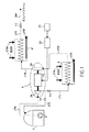
図1に示すサイクルでは、使用する単一の高圧モーター駆動ポンプを、上述のようなモーター駆動ターボポンプ5の高圧ポンプ26により構成する。そして、ポンプ26をガスパイプライン200に供給するのに必要な圧力より高い圧力を生じるように設計する。タンク1から流れて来たガスは、第1熱交換器かつ蒸発器4にて蒸発および周囲温度に加熱した後、タービン29にてパイプライン200の入口圧力まで低下して膨張し、これにより機械的エネルギーを伝達して、ポンプ26を駆動するために電気機械11が供給する必要のあるエネルギーが低減される。これは、気体状態における単位圧力当りのエンタルピーの変化が液体状態における場合より大きいことによる。
In the cycle shown in FIG. 1, a single high-pressure motor-driven pump to be used is constituted by the high-
タービン29より送給されるガスは周囲より低い温度にあるため、回路174’により送給され、および回路175’により排出される周囲温度の水(海水または河川水)を用いて動作する第2熱交換器4’に通過させることによって更なる加熱に付す必要がある。
Since the gas delivered from the
第1熱交換器かつ蒸発器4から水排出回路175により通常排出される熱水でタービン29の入口における温度を上昇させるため、第1熱交換器かつ蒸発器4に水を導入する回路174へ、近隣の発電プラントまたは何らかの他のコジェネレーション源から損失熱を回収することによって得られる熱水、例えば約40℃〜50℃の温度の水を導入することができる。熱水を用いる場合、タービン29の下流に位置する第2熱交換器4’を省略してよく、タービン29より生じるエネルギーが大幅に増大する。そのような場合、タービン29より送給されるエネルギーはポンピングに必要な全エネルギーを供給でき、およびオルタネータ11を発電機として動作させ得る正のバランスを提供することまでも可能である。
To the
図1中、高圧ポンプ26から熱交換器かつ蒸発器4の入口に至る送給ライン171に位置する調整バルブV1を認めることができる。熱交換器かつ蒸発器4の出口はライン172によりタービン29の入口に接続される。タービン29の出口はライン176により第2熱交換器かつ蒸発器4’に接続される。その出口はライン177に接続され、ライン177はパイプライン200へと続き、また圧力調整器を構成する圧縮器−蒸発器システムからパイプラインを隔離するためにライン177に位置するバルブV2を有する。
In FIG. 1, it is possible to recognize the regulating valve V <b> 1 located in the
バルブV3は高圧ポンプ26の出口に並列に接続されてタンク1に戻る冷却ライン173に位置する。
The valve V3 is connected to the outlet of the high-
図1に示す態様において、モーター駆動ターボポンプ5はタービン29より上流かつポンプ26より下流に位置する第1熱交換器かつ蒸発器4と常に関連付けられ、そして適当な場合にはこれはタービン29より下流に位置する第2熱交換器かつ蒸発器4’とも関連付けられる。
In the embodiment shown in FIG. 1, the motor driven
図1の態様により、モーター駆動ターボポンプ5の各タービン29に流れを分配するための複雑なシステムを組み込むことを回避できる。既存の装置に加えて冷却または再循環のための装置を高圧ポンプ26に対して設ける必要はない。反対に、電力調整回路12が存在することで、モーター駆動ターボポンプ5の速度を調整でき、よって適当な場合には高圧ポンプ26からライン171に至る送給部に位置する調整バルブV1を省略できる。
The embodiment of FIG. 1 avoids incorporating a complex system for distributing the flow to each
図7は図1に示す適用例にて実施されるモーター駆動ターボポンプ内の流れをたどる経路および様々な構成要素の配置を示す。 FIG. 7 shows the path following the flow in the motor driven turbopump implemented in the application example shown in FIG. 1 and the arrangement of the various components.
図7では、動的シールが二重バリア28a、28bを形成して動的シール間に空洞部27を規定し、動的シールを通るリークは空洞部27からライン63に通じて集めることができ、ライン63は空洞部27から回収した流体をHPポンプ26の入口に再投入していることがわかる。
In FIG. 7, the dynamic seal forms a
図7中、参照番号60はポンプ26の最後の遠心ホイールの出口から得た、または適当な場合にはタンク1が配置されたターミナルの高圧液体ラインから直接に得た液体状態の天然ガスを流体ベアリング31に供給するラインを示す。流体ベアリング31が供給を受ける割合は目盛付(calibrated)オリフィス64により測定される。液体天然ガスは流体ベアリングの出口から低圧で集められ、ライン61によりポンプ26の入口に再投入される。
In FIG. 7,
電気機械11の冷却流れをタービン29の入口から得、目盛付オリフィス64’に通じて膨張させ、そして電気機械11の出口に位置する第2目盛付オリフィス64’’に通じて更なる膨張に付し、その後、ライン62aによりポンプ26の入口に再投入する。
The cooling flow of the
また、図7は流体ベアリング31を冷却するための回路173に位置する3ポートバルブも図示する。
FIG. 7 also illustrates a three-port valve located in a
モーター駆動ターボポンプのケーシングを貫通するダクトまたは外部配管を通じて流体ベアリング31に供給することができ、および電気機械11を冷却することができる。
The
モーター駆動ターボポンプ5の回転アセンブリに作用する軸方向の力をバランスさせるために液圧デバイス49を用いる場合、力の合力を相殺するように圧力場を適応させるため、このデバイスにはバランス板の裏側を通る流れに較正(calibration)デバイスが設けられる。
When using the
図2は図1のサイクル同様、(図10に示すような)ターミナルの常套の高圧モーター駆動ポンプ303をモーター駆動ターボポンプ5で置換したエネルギー回収サイクルのもう1つの例を示す。しかしながら、図2の態様では、モーター駆動ターボポンプ5の高圧ポンプ26の出口における圧力は上昇させていない。ポンプ26を通過する流体流れのフラクションを熱交換器かつ蒸発器4の出口から取り出し、隔離バルブV4を備えるライン172に通じてタービン29に搬送し、タービン29にて低圧まで膨張させ、その後、凝縮器として機能するもう1つの熱交換器6を通過させるためにライン176を通じて排出するものとする。熱交換器かつ凝縮器6の回路6bからの再液化流体を液体の形態で、隔離バルブV5を備えるライン182により容積7に再投入する。この容積7は凝縮物中に残留し得る気泡を排除するように機能するものであり、高圧ポンプ26の入口に位置する。
FIG. 2 shows another example of an energy recovery cycle in which the conventional high pressure motor driven pump 303 (as shown in FIG. 10) is replaced by a motor driven
HPポンプ26を容積7と接続するライン170aからHPポンプ26によって得られた液化ガスの主要な流れは該ポンプを離れる際に調整バルブV1を備えるライン171へ流れ、そして凝縮器6の回路6aを通過する。凝縮器6の回路6aからの出口流れは、周囲温度の水(回路174に通じて導入され、そして回路175により排出される)を用いる熱交換器4の入口に通じる隔離バルブV6を備えるライン178により取り出される。凝縮器6の回路6aを通過する液体の流れは、タービン29の出口にあるライン176に流れる流体を回路6bにより凝縮することのできる冷源として機能する。
The main flow of liquefied gas obtained by the
図1の態様と同様に、タービン29の入口における温度を上昇させ、よってタービンにて回収されるエネルギーを増大させるため、周囲温度まで加熱する熱交換器4からの回路174をコジェネレーションタイプの熱水源に接続することができる。
Similar to the embodiment of FIG. 1, to increase the temperature at the inlet of the
凝縮器6の回路6aの出口において、冷却バルブV3bを有するライン177は冷却回路に供給するよう機能する。
At the outlet of the circuit 6a of the condenser 6, a
熱交換器かつ蒸発器4の出口は、隔離バルブV2を備えるライン179によりガスパイプライン200に接続される。
The outlet of the heat exchanger and the evaporator 4 is connected to the
バルブV4およびV5はタービン29および凝縮器6を含む回路を隔離するように機能する。ライン172に位置するバルブV4も、タービン29に搬送される流体の流れを調整することができる。
Valves V4 and V5 function to isolate the
「ボイルオフガス」として知られている少量の再圧縮蒸発させた天然ガスをHPポンプの供給ラインに再導入するため、バッファ容積7を置換するのに、ターミナルの再取入器(reincorporator)(概略図に図示せず)も使用できることに留意されるべきである。 A terminal reincorporator (schematically) is used to replace the buffer volume 7 in order to re-introduce a small amount of recompressed vaporized natural gas, known as “boil-off gas”, into the HP pump supply line. It should be noted that (not shown in the figure) can also be used.
HPポンプ26について満足できる開始条件を確保するには、最初に凝縮器6の低温流体側を液体天然ガスの温度まで冷却する必要がある。また、蒸発器6を隔離するようにバルブV6を閉じたままバルブV3bを開けることによって形成される流体流れにより、HPポンプ部分26も冷却する(図2を参照のこと)。電気回路12の制御下にてモーターモードで動作し、よって、圧力を徐々に上昇させるように機能するオルタネータ11によりモーター駆動ターボポンプ5を始動させる。タービン29を駆動させるため、バルブV4およびV5を徐々に開く。タービン29に搬送される流れを調整バルブとしても機能するバルブV4により調整する。ポンプを停止させると、タービン29への供給を停止するためにバルブV4を閉じてよく、その後、モーター11を停止させてよい。
To ensure a satisfactory starting condition for the
モーター駆動ターボポンプ5を制御および調整する電気回路12が存在することにより、HPポンプ26からの送給部に位置する調整バルブV1を省略することが考えられる。
Due to the presence of the
液体移送ラインを最小限にし、および低温(または冷たい)領域の隔離を簡単にする(断熱材被覆またはコールドボックス)ため、モーター駆動ターボポンプ5および凝縮器6を含むアセンブリを共通のプラットフォーム上にひとまとめにすることが好都合であり得る。
To minimize the liquid transfer line and simplify the isolation of the cold (or cold) area (insulation coating or cold box), the assembly including the motor driven
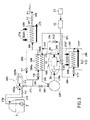
図3は本発明に従ってモーター駆動ターボポンプ105を実施するサイクルのもう1つの例を示す。
FIG. 3 shows another example of a cycle implementing a motor driven
図3に示す態様では、図10のモーター駆動ポンプ303に類似する常套の高圧モーター駆動ポンプ103を引き続き使用し、このポンプ103は常套の電気モーターであり得るモーター103bによって駆動される高圧ポンプ103aを含んで成る。
In the embodiment shown in FIG. 3, a conventional high-pressure motor-driven
既存のターミナルのモーター駆動ポンプ103を含む図3の態様では、高圧ポンプ103aの出口ライン171を常套の熱交換器かつ蒸発器104に接続する高圧ライン184、186に低損失水頭調整バルブV7が挿入され、熱交換器かつ蒸発器104の出口は隔離バルブV2を備えるライン187を通じてガスパイプライン200に接続される。熱交換器かつ蒸発器104は水入口回路174および水出口回路175を常套の様式で含んで成る。
In the embodiment of FIG. 3 including the
低損失水頭調整バルブV7を備えるライン184と並列に、調整バルブV8を備えるライン185も凝縮器106の回路106aに接続され、回路106aの出口は熱交換器かつ蒸発器104の入口ライン186に接続される。
In parallel with
バルブV7およびV8の機能は、凝縮器106の回路106aへと取り出される液化ガスの流れを調整することである。
The function of valves V7 and V8 is to regulate the flow of liquefied gas taken to
また、バルブV8は凝縮器106をターミナルの排出回路から隔離することもでき、およびエネルギー回収ループを構築するために使用される。ターミナルが排出ライン171にて更なる損失水頭を許容できないならば、バルブV7を凝縮器106に至るライン185に組み込まれた循環ポンプで置換し、そして、バルブV8および/または循環ポンプを制御することによって凝縮器を通る流量を調整することができる。
Valve V8 can also isolate
図3の態様では、エネルギー回収ループには上述のタイプのモーター駆動ターボポンプ105、熱水または周囲温度の水を用いる熱交換器かつ蒸発器108、凝縮器106の「高温(または熱い)」回路106bまたは区画、ポンプ26より上流に位置するバッファ容積107、流体を移送するための配管、および該ループが適切に作動することを確保するための種々のバルブが含まれる。回収ループはクローズドサイクルにて動作する。
In the embodiment of FIG. 3, the energy recovery loop includes a motor driven
エネルギー回収ループに導入された流体は、高圧ポンプ103aより下流にて、容積107に供給するバルブV9を備えるライン183によってターミナルの排出ラインから取り出される。
The fluid introduced into the energy recovery loop is taken from the terminal discharge line by a
熱交換器かつ蒸発器108は、周囲温度または近隣にて利用可能なコジェネレーション源から送給されるそれよりわずかに高い温度の水を自身に対して供給する回路174’’を有し、この水は回路175’’により排出される。
The heat exchanger and
容積107よりライン107bを通じて送給される流体はモーター駆動ターボポンプ105のポンプ26の入口に液体として入り、該ポンプ26により加圧され、そして水熱交換器108にて蒸発させ、周囲温度まで、または熱交換器かつ蒸発器108の入口174’’にて熱水を用いるときはより高い温度まで再加熱される。その後、ライン192、193内を流れる流体はタービン29にて膨張し、このタービン29にはポンピングのために必要な分より多くの機械的エネルギーが伝えられる。ライン176、195を通じてタービン29を出た流体は次いで凝縮器106の回路106bにて低圧で液化し、そしてその後、ポンプ26の入口に配置された容積107へライン196により再循環する。
The fluid fed from the
過剰な機械的エネルギーは、発電機モードで動作する電気機械11により電気に変換し、そしてターミナルまたは現地の電気ネットワークに送給できる。
Excess mechanical energy can be converted to electricity by the
図3の態様では、モーター駆動ターボポンプ105、熱交換器かつ蒸発器108、および凝縮器106を必須として含むエネルギー回収ループを以下のようにして実現することができる。
In the embodiment of FIG. 3, an energy recovery loop including the motor-driven
タンク1を配置したターミナルを、バルブV7を開に、かつバルブV8を閉にした状態でエネルギーを回収することなく常套的に運転する。エネルギー回収ループを作動させるため、第1工程は液体天然ガスを凝縮器106の低温区画106aに通じて流すようにバルブV7およびV8を動かすものであり、バルブV8は凝縮器106を徐々に冷やすためにゆっくりと開く。
The terminal in which the
続く工程は、熱交換器108の入口にあるライン189に位置するバルブV11を閉に、かつライン191に位置するバルブV10を開にした状態でバルブV9を天然ガスのために開くことによってエネルギー回収ループを満たすものである。冷却によって起こる蒸発物はターミナルを冷却するための収集回路に排出され、該容積内の圧力が大きすぎるようになるとバルブV9を再び閉じる。容積107に液体が十分に存在するとき、モーター駆動ターボポンプ105をモーターモードで作動させることができ、ポンプを通過する液体循環を確立するように極めて低速でポンピングする。この間、流体ベアリング31を通る流体流れを確立し、よってこれらを冷却するために、流体ベアリング31からのリークを集めて、3ポートバルブV15(図8を参照のこと)に通じて低圧収集回路へ排出する。このシーケンス(または手順)の最後に、モーター駆動ターボポンプ105のポンプ部分およびベアリング、ならびに凝縮器106の高温区画106bも液体ガス温度にあり、またバッファ容積107はループの適切な動作を確保するのに十分な量の液体で満たされる。その後、バルブV9を閉じ、ベアリングリークをターミナルに排出するバルブV15も同様とし、そしてループをガス放出から再び隔離する。
The subsequent process is energy recovery by opening valve V9 for natural gas with valve V11 located in
第3工程は、電気回路12を用いてモーター駆動ターボポンプ105をモーターモードにて始動し、タービン29に供給するようにバルブV11を開に、かつバルブV10を閉にした状態とするものであり、これにより電気回路12は徐々にモーターから交代して、ポンプ26の必要量より過剰なエネルギーを送給し始め、機械を発電機モードに切り換えることができる。
In the third step, the motor-driven
エネルギー回収ループは、タービン29の入口における温度を調整し、よって凝縮器106の出口における温度を調整することを可能にするために熱交換器かつ蒸発器108を迂回するバイパスバルブV12をライン190に有し、またこれは流れの全部または一部をライン194に逸らすためにタービン29を迂回するバルブV13も含み、これにより、発電機またはその電子機器が故障する非常時にモーター駆動ターボポンプ105を停止することができ、また必要であればモーター駆動ターボポンプ105の速度を調整することができる。好都合には、電力回路もモーター駆動ターボポンプ105の速度を調整するように機能でき、この場合はポンプ流れの全体がタービン29を通過するので性能を損なうことがない。
The energy recovery loop regulates the temperature at the inlet of the
バルブV11を閉じ、かつバルブV10を開くことによってループを停止し、そして熱交換器かつ蒸発器108に収容されたガスのみをモーター駆動ターボポンプ105のタービン29に供給し、よって上流ラインを徐々に停止する。非常停止が必要な場合、バルブV13を開けることによって作動させることができる。
The loop is stopped by closing the valve V11 and opening the valve V10, and only the gas contained in the heat exchanger and the
熱損失を回避するためおよび回収ループを流体で満たしつつも動作していない状態で一時停止させ得るために、モーター駆動ターボポンプ105の部分26およびバッファ容積107、凝縮器106ならびに液体ラインをコールドボックスに収容し、または断熱材で被覆する。好都合には、容積107、モーター駆動ターボポンプ105、凝縮器106、およびバルブ装置を共通のプラットフォームに一体化することができる。
In order to avoid heat loss and to allow the recovery loop to be paused while filling with fluid but not operating, the
図4は本発明に従ってモーター駆動ターボポンプ105を実施するサイクルの更にもう1つの例を示す。
FIG. 4 shows yet another example of a cycle implementing a motor driven
図4に示す解決策では、図5を参照して説明したものと同様の原理を用いているが、図3における熱交換器108のような追加の水熱交換器は用いていない。
The solution shown in FIG. 4 uses a principle similar to that described with reference to FIG. 5, but does not use an additional water heat exchanger such as
先の態様と同様、ターミナルによりタンク1から送給される液化ガスのフラクションは、ターミナルのものと同じ天然ガスを用いるオープンなエネルギー回収サイクルにて冷源として機能する凝縮器106に導くため、常套の蒸発器104より上流にある従来の高圧ポンプ103aの出口から取り出される。
As in the previous embodiment, the fraction of the liquefied gas delivered from the
図4の態様では、ターミナルの常套の熱交換器かつ蒸発器104の出口から天然ガスのフラクションを取り出して、モーター駆動ターボポンプ105のタービン29にて膨張させ、その後、膨張させたガスを液化させるためにタービン29から凝縮器106の回路106bに通じ、容積107に再導入した後、ライン170bに流し、モーター駆動ターボポンプ105のポンプ26により液体形態のまま加圧し、続いて、ライン200および隔離バルブV14により熱交換器かつ蒸発器104の入口にてターミナルからの主要な流れに、または場合により、ポンプ103aから取り出され、および凝縮器106の回路106aに対して冷源として機能する流れのいずれかに再投入する。流れを凝縮器に供給する場合、モーター駆動ターボポンプ105のポンプ26はターミナルの高圧ポンプ103aと同等の高い圧力を提供する必要がある。
In the embodiment of FIG. 4, the natural gas fraction is taken out from the outlet of the conventional heat exchanger and
上述のように、図4に示す解決策は図3のものと、エネルギー回収ループにターミナルの熱交換器かつ蒸発器104を使用する点で異なっている。これは、高圧ラインに対する上記の改変(分岐接続部、バルブV7およびV8)に加えて、2つの更なる接合部(またはインターフェース)、第1はモーター駆動ターボポンプ105から流れて来る液体天然ガスを再導入するように熱交換器かつ蒸発器104より上流にあり、第2はモーター駆動ターボポンプ105のタービン29に供給するように該蒸発器104より下流にある接合部を形成することによって、既存のターミナルを容易に適用できる。そして、回収ループは図4に示す凝縮器106、モーター駆動ターボポンプ105、および上流容積107を配管およびバルブと共に含んで成り、および上述の実施により正当なものと根拠付けられる。
As described above, the solution shown in FIG. 4 differs from that of FIG. 3 in that a terminal heat exchanger and
図4の態様を実施する場合、図3の態様の場合と同様、第1工程は冷たい流体を凝縮器106の回路106aに供給するためにバルブV7、V8を動かすものである。
When implementing the embodiment of FIG. 4, as in the embodiment of FIG. 3, the first step is to move the valves V7, V8 to supply cold fluid to the
バルブV4およびV14を閉に、およびライン198にあるバルブV10bを開にした状態でバルブV9を開くことによって、バッファ容積107、モーター駆動ターボポンプ105、ポンプ部分103a、および凝縮器106の回路106b(高温側)を含んで成る回路を満たす。上記のように、ポンプ26を流体循環ポンプとして使用でき、およびループの「液体」部分を冷却するように、オルタネータ11を極めて低速のモーターモードでの運転状態に設定する。この段階の間、流体ベアリング31からのリークは、上記のようにバルブV15を通じてターミナルの低圧収集回路に排出する。
By opening valve V9 with valves V4 and V14 closed and valve V10b in
ポンプ26を適切に運転可能とするのに十分に回路を冷却し、および十分な量の液体をバッファ容積17が示すと、バルブV10bおよびV9を閉じ、タービン29の入口にあるバルブV4を徐々に開き、同時に、ポンプ26を運転状態に設定するために電気機械11をモーターモードで作動させる。電気機械11は、タービン29から送給される動力が発電機モードへの移行を可能なものと直ちに発電機モードに移行し、ポンプ26の出口における圧力がターミナルの蒸発器104の入口における圧力に達するとバルブV14を開ける。
When the circuit is cooled sufficiently to allow the
ループで運転しながら、ライン199にあるバルブV12を開度に作用することによって、タービン29の入口における温度を調節することができる。モーター駆動ターボポンプ105の回転速度は電気制御回路により調整する。
The temperature at the inlet of the
タービン29に供給するバルブV4を閉じることによって回収ループを停止し、高圧の液体がライン197を介してポンプ26に通り逆方向に流れるのを防止するためにバルブV14を閉じる。上述の解決策とは異なって、バルブV4を一旦閉じると、タービン29より上流に大量のガスが捕捉されることはなく、よって、非常停止のためにタービン29の周りにバイパスを設ける必要はない。
The recovery loop is stopped by closing valve V4, which feeds
バッファ容積107には、ループを空にでき、および過剰のガスをターミナルの回収回路へと排出できるバルブシステムが備えられる。
The
図4の解決策は、凝縮器106、モーター駆動ターボポンプ105、容積107、および液体搬送装置を共通のプラットフォームに一体化した構成に首尾よく適する。
The solution of FIG. 4 is well suited to a configuration in which the
図8は、モーター駆動ターボポンプ5または105の様々な構成要素およびその内部の流れを図2〜4を参照して上述したような適用にいかにして構成するかを示す。
FIG. 8 shows how the various components of the motor-driven
図8中、図1の態様に適用可能な図7の概略図とは異なって、動的シール28a、28bからおよびオルタネータの冷却部からライン62bを通じて回収したリークを、ポンプ26の入口ではなく、タービン29より下流の位置にライン63を通じて排出していることが認められる。
In FIG. 8, unlike the schematic of FIG. 7 applicable to the embodiment of FIG. 1, the leak recovered from the
図7および8の概略図で共通する他の要素については上記に説明していない。 Other elements common to the schematics of FIGS. 7 and 8 have not been described above.
説明した様々な態様において、熱交換器かつ蒸発器は、例えば水滴下(water-trickle)タイプまたはチューブ・アンド・グリルタイプ、あるいは実に、熱水容器内にコイルを有するタイプの熱交換器であってよいことに留意されるべきである。 In the various embodiments described, the heat exchanger and evaporator are, for example, a water-trickle type or tube and grill type, or indeed a type of heat exchanger having a coil in a hot water container. It should be noted that
凝縮器106は代表的にはプレート熱交換器またはチューブ・アンド・グリルタイプ熱交換器である。
The
凝縮器106および/または熱交換器4もしくは108と関連付けられ、また、適当な場合には従来の熱交換器かつ蒸発器104および/または常套のモーター駆動ポンプ103aと協働するモーター駆動ターボポンプ5もしくは105を参照しつつ、本発明のシステムを様々な態様にて上述する。
Motor driven
しかしながら、本発明は多数の構成要素を有するシステムに適用できる。 However, the present invention is applicable to a system having a large number of components.
伝統的には、再ガス化ターミナルは、モーター駆動HPポンプのバッテリを熱交換器かつ蒸発器のバッテリに1つまたは2つの高圧ラインにより接続しつつ、異なる機能をひとまとめにすることに基づいて構成される。用いるポンプおよび蒸発器の数はターミナルの予定送給速度に依存し、HPポンプからの送給部に位置する調整バルブおよびまた蒸発器より下流に位置する調整バルブも、パイプラインの入口における流量および圧力を調節するように機能する。 Traditionally, the regasification terminal is based on connecting different functions together while connecting the motor-driven HP pump battery to the heat exchanger and evaporator battery via one or two high-pressure lines. Is done. The number of pumps and evaporators used depends on the planned feed rate of the terminal, and the regulating valve located in the feed section from the HP pump and also the regulating valve located downstream from the evaporator also has a flow rate at the inlet of the pipeline and It functions to adjust the pressure.
モーター駆動HPポンプを始動させるには特別なシーケンスを要する。まず第1に、液体天然ガスを低圧にてモーター駆動ターボポンプに循環させることにより、モーター駆動ターボポンプを液体ガス温度に冷却する必要があり、この液体天然ガスはその後、運転中にポンプにて液体中に気泡が存在してキャビテーションが起こることを回避するために所定の収集回路に回収する。パージバルブ3V3を使用するのはこの冷却シーケンスである(図10を参照のこと)。続く始動の間、およびハンマー作用を避けるべくポンプ流体中で急激な圧力上昇が起こることを回避するために、ポンプの送給部から流れのフラクションを取り出して、より高圧に適合するもう1つの収集回路に再循環させる。本発明に関して、図1〜4の様々な態様にて説明したように、冷却回路に関連付けられたパージポンプ3V2bもモーター駆動ターボポンプ5もしくは105と一緒に使用される。
Starting the motor-driven HP pump requires a special sequence. First of all, it is necessary to cool the motor-driven turbo pump to the liquid gas temperature by circulating the liquid natural gas to the motor-driven turbo pump at a low pressure, which is then pumped during operation. In order to avoid the presence of bubbles in the liquid and cavitation, the liquid is collected in a predetermined collecting circuit. It is this cooling sequence that uses the purge valve 3V3 (see FIG. 10). During subsequent start-up and to avoid a sudden pressure build-up in the pump fluid to avoid hammering, another collection is taken that draws a fraction of the flow from the pump feed and adapts to a higher pressure. Recirculate to circuit. In connection with the present invention, the purge pump 3V2b associated with the cooling circuit is also used with the motor driven
Claims (22)
システムは、軸方向吸引ステージおよび少なくとも1つの遠心ホイールを含む少なくとも1つの高圧ポンプ(26)、タービン(29)、ならびにモーターモードまたは発電機モードにて使用可能であり、および高圧ポンプ(26)とタービン(29)との間に位置する中央電気機械(11)を有する、極めて高い曲げ剛性を有する回転アセンブリを共通軸線上に含んで成るモーター駆動ターボポンプ(5;105)より構成される少なくとも1つのターボ機械を含んで成り、該モーター駆動ターボポンプ(5;105)は周囲の媒体に対して静的シールのみを提供する堅いケーシング(25)内にコンパクトに配置され、モーター駆動ターボポンプ(5;105)の回転アセンブリは回転危険速度の励振域外にとどまりながらも12,000rpm以上の高速回転を示すように適用され、モーター駆動ターボポンプ(5;105)の内側部分の全てがタンク(1)に収容される液化ガスと同じ低温流体中に浸漬され、異なる熱力学的条件下にあるモーター駆動ターボポンプ(5;105)の内側空洞部が非接触動的シール(28)により隔てられ、および電気ネットワーク(13)に接続された電力回路(12)が中央電気機械(11)をモーターモードまたは発電機モードに制御するように機能することを特徴とするシステム。 A compressor-evaporator system for liquefied gas contained in a tank (1), withdrawing and pumping means (2) for extracting and feeding the liquefied gas to the outside of the tank (1) under low pressure; High pressure pump means, evaporator means (4, 4 '; 104) operating by heat exchange with liquid, and means for transferring gas to the conditioning and gas pipeline (200),
The system is usable in at least one high pressure pump (26) including an axial suction stage and at least one centrifugal wheel, a turbine (29), and a motor mode or a generator mode, and a high pressure pump (26) At least one consisting of a motor driven turbopump (5; 105) comprising on a common axis a rotating assembly with very high bending stiffness having a central electric machine (11) located between the turbine (29) Comprising a turbomachine, the motor-driven turbo pump (5; 105) being compactly arranged in a rigid casing (25) providing only a static seal against the surrounding medium, and the motor-driven turbo pump (5 105) the rotating assembly stays outside the critical rotation speed excitation range but at 12:00 Applied to exhibit high speed rotation above rpm, all of the inner part of the motor driven turbo pump (5; 105) is immersed in the same cryogenic fluid as the liquefied gas contained in the tank (1), with different thermodynamics A power circuit (12) connected to an electrical network (13) is separated by a non-contact dynamic seal (28) and the inner cavity of the motor-driven turbo pump (5; 105) under conditions is connected to a central electric machine ( 11) A system that functions to control the motor mode or the generator mode.
System according to any of the preceding claims, characterized in that it is applied to liquefied natural gas (LNG) type liquefied gas.
Applications Claiming Priority (1)
| Application Number | Priority Date | Filing Date | Title |
|---|---|---|---|
| FR0413486A FR2879720B1 (en) | 2004-12-17 | 2004-12-17 | COMPRESSION-EVAPORATION SYSTEM FOR LIQUEFIED GAS |
Publications (2)
| Publication Number | Publication Date |
|---|---|
| JP2006194440A true JP2006194440A (en) | 2006-07-27 |
| JP2006194440A5 JP2006194440A5 (en) | 2008-12-11 |
Family
ID=35395413
Family Applications (1)
| Application Number | Title | Priority Date | Filing Date |
|---|---|---|---|
| JP2005363437A Ceased JP2006194440A (en) | 2004-12-17 | 2005-12-16 | Compression-evaporating system for liquefied gas |
Country Status (6)
| Country | Link |
|---|---|
| US (1) | US7406830B2 (en) |
| EP (1) | EP1672270B1 (en) |
| JP (1) | JP2006194440A (en) |
| KR (1) | KR20060069346A (en) |
| ES (1) | ES2314599T3 (en) |
| FR (1) | FR2879720B1 (en) |
Cited By (3)
| Publication number | Priority date | Publication date | Assignee | Title |
|---|---|---|---|---|
| WO2012117806A1 (en) * | 2011-02-28 | 2012-09-07 | 三菱重工業株式会社 | Liquefied gas regasificaion device and method for manufacturing regasified gas |
| CN109723966A (en) * | 2019-01-25 | 2019-05-07 | 太平洋海洋工程(舟山)有限公司 | A kind of liquified natural gas regas system for FSRU |
| WO2020059935A1 (en) * | 2018-09-20 | 2020-03-26 | 한국생산기술연구원 | Composite bearing, and power generator and power generation system including same |
Families Citing this family (63)
| Publication number | Priority date | Publication date | Assignee | Title |
|---|---|---|---|---|
| DE102005038273A1 (en) * | 2005-08-02 | 2007-02-08 | Linde Ag | Machine with a rotatable rotor |
| JP2007211597A (en) * | 2006-02-07 | 2007-08-23 | Hitachi Ltd | Plant facilities |
| FI122435B (en) * | 2006-10-18 | 2012-01-31 | Savonia Power Oy | steam Power plant |
| US8128021B2 (en) | 2008-06-02 | 2012-03-06 | United Technologies Corporation | Engine mount system for a turbofan gas turbine engine |
| US20140174056A1 (en) | 2008-06-02 | 2014-06-26 | United Technologies Corporation | Gas turbine engine with low stage count low pressure turbine |
| US8616323B1 (en) | 2009-03-11 | 2013-12-31 | Echogen Power Systems | Hybrid power systems |
| US9014791B2 (en) | 2009-04-17 | 2015-04-21 | Echogen Power Systems, Llc | System and method for managing thermal issues in gas turbine engines |
| JP5681711B2 (en) | 2009-06-22 | 2015-03-11 | エコージェン パワー システムズ インコーポレイテッドEchogen Power Systems Inc. | Heat effluent treatment method and apparatus in one or more industrial processes |
| US9316404B2 (en) | 2009-08-04 | 2016-04-19 | Echogen Power Systems, Llc | Heat pump with integral solar collector |
| US8813497B2 (en) | 2009-09-17 | 2014-08-26 | Echogen Power Systems, Llc | Automated mass management control |
| EP2478311B1 (en) * | 2009-09-17 | 2019-07-31 | Shell International Research Maatschappij B.V. | Off-shore structure comprising two power systems and method of powering the same |
| US8096128B2 (en) * | 2009-09-17 | 2012-01-17 | Echogen Power Systems | Heat engine and heat to electricity systems and methods |
| US8613195B2 (en) | 2009-09-17 | 2013-12-24 | Echogen Power Systems, Llc | Heat engine and heat to electricity systems and methods with working fluid mass management control |
| US8869531B2 (en) | 2009-09-17 | 2014-10-28 | Echogen Power Systems, Llc | Heat engines with cascade cycles |
| KR101121721B1 (en) * | 2010-01-28 | 2012-02-28 | 에스티엑스조선해양 주식회사 | Floating type LNG regasification unit |
| AT509334B1 (en) * | 2010-07-09 | 2011-08-15 | Lo Solutions Gmbh | METHOD AND DEVICE FOR PROVIDING ELECTRICAL AND THERMAL ENERGY, ESPECIALLY IN A PORT SYSTEM |
| US8963354B2 (en) * | 2010-09-13 | 2015-02-24 | Ebara International Corporation | Power recovery system using a rankine power cycle incorporating a two-phase liquid-vapor expander with electric generator |
| US8616001B2 (en) * | 2010-11-29 | 2013-12-31 | Echogen Power Systems, Llc | Driven starter pump and start sequence |
| US8783034B2 (en) | 2011-11-07 | 2014-07-22 | Echogen Power Systems, Llc | Hot day cycle |
| US8857186B2 (en) | 2010-11-29 | 2014-10-14 | Echogen Power Systems, L.L.C. | Heat engine cycles for high ambient conditions |
| US8542085B2 (en) * | 2011-02-28 | 2013-09-24 | GM Global Technology Operations LLC | High frequency rotary transformer for synchronous electrical machines |
| US9239012B2 (en) | 2011-06-08 | 2016-01-19 | United Technologies Corporation | Flexible support structure for a geared architecture gas turbine engine |
| US9631558B2 (en) | 2012-01-03 | 2017-04-25 | United Technologies Corporation | Geared architecture for high speed and small volume fan drive turbine |
| US9062898B2 (en) | 2011-10-03 | 2015-06-23 | Echogen Power Systems, Llc | Carbon dioxide refrigeration cycle |
| JP5645858B2 (en) * | 2012-02-27 | 2014-12-24 | 株式会社日立製作所 | Permanent magnet pump motor |
| US20130219907A1 (en) * | 2012-02-29 | 2013-08-29 | Frederick M. Schwarz | Geared turbofan architecture for improved thrust density |
| PL2815168T3 (en) * | 2012-05-16 | 2016-07-29 | Tge Marine Gas Eng Gmbh | Device for supplying gas |
| US20150308351A1 (en) | 2012-05-31 | 2015-10-29 | United Technologies Corporation | Fundamental gear system architecture |
| US8756908B2 (en) | 2012-05-31 | 2014-06-24 | United Technologies Corporation | Fundamental gear system architecture |
| US8572943B1 (en) | 2012-05-31 | 2013-11-05 | United Technologies Corporation | Fundamental gear system architecture |
| US8742604B2 (en) * | 2012-06-06 | 2014-06-03 | Energy Recovery, Inc. | Systems and methods for combined flow control and electricity generation |
| KR20150143402A (en) | 2012-08-20 | 2015-12-23 | 에코진 파워 시스템스, 엘엘씨 | Supercritical working fluid circuit with a turbo pump and a start pump in series configuration |
| FR2994731B1 (en) * | 2012-08-22 | 2015-03-20 | Snecma | COOLING PROCESS |
| US9118226B2 (en) | 2012-10-12 | 2015-08-25 | Echogen Power Systems, Llc | Heat engine system with a supercritical working fluid and processes thereof |
| US9341084B2 (en) | 2012-10-12 | 2016-05-17 | Echogen Power Systems, Llc | Supercritical carbon dioxide power cycle for waste heat recovery |
| CN102996469B (en) * | 2012-12-24 | 2015-09-30 | 成都安迪生测量有限公司 | A kind of low temperature immersed pump of multi-head spiral sealing |
| CA2896461A1 (en) | 2012-12-28 | 2014-07-03 | General Electric Company | Cryogenic fuel system and method for delivering fuel in an aircraft |
| DE102013200572A1 (en) * | 2013-01-16 | 2014-07-17 | Siemens Aktiengesellschaft | Liquefied natural gas regasification apparatus and related method |
| CA2899163C (en) | 2013-01-28 | 2021-08-10 | Echogen Power Systems, L.L.C. | Process for controlling a power turbine throttle valve during a supercritical carbon dioxide rankine cycle |
| WO2014117068A1 (en) | 2013-01-28 | 2014-07-31 | Echogen Power Systems, L.L.C. | Methods for reducing wear on components of a heat engine system at startup |
| BR112015021396A2 (en) | 2013-03-04 | 2017-08-22 | Echogen Power Systems Llc | HEAT ENGINE SYSTEMS WITH HIGH USEFUL POWER SUPERCRITICAL CARBON DIOXIDE CIRCUITS |
| WO2014159520A1 (en) * | 2013-03-14 | 2014-10-02 | Echogen Power Systems, L.L.C. | Controlling turbopump thrust in a heat engine system |
| FR3005687B1 (en) | 2013-05-20 | 2017-09-15 | Snecma | TURBOPOMPE WITH ANTI-VIBRATION SYSTEM |
| KR101525679B1 (en) * | 2013-10-22 | 2015-06-03 | 현대중공업 주식회사 | A Liquefied Gas Treatment System |
| WO2016073252A1 (en) * | 2014-11-03 | 2016-05-12 | Echogen Power Systems, L.L.C. | Active thrust management of a turbopump within a supercritical working fluid circuit in a heat engine system |
| CN107407229B (en) * | 2015-01-30 | 2020-03-13 | 大宇造船海洋株式会社 | Fuel supply system and method for ship engine |
| US10167732B2 (en) * | 2015-04-24 | 2019-01-01 | Hamilton Sundstrand Corporation | Passive overspeed controlled turbo pump assembly |
| CN105240127A (en) * | 2015-10-26 | 2016-01-13 | 成都华气厚普机电设备股份有限公司 | Fuel gas supply control system of engine trial run platform |
| PL3455543T3 (en) | 2016-05-10 | 2021-02-08 | Wärtsilä Finland Oy | Tank arrangement |
| PL3455544T3 (en) | 2016-05-10 | 2020-12-14 | Wärtsilä Finland Oy | Bilobe or multilobe tank |
| KR102026046B1 (en) * | 2016-05-10 | 2019-09-27 | 바르실라 핀랜드 오이 | Tank array |
| JP6845675B2 (en) * | 2016-12-08 | 2021-03-24 | 川崎重工業株式会社 | Raw material gas liquefier and its control method |
| US10712235B2 (en) * | 2017-04-24 | 2020-07-14 | Energy Recovery, Inc. | System and method for monitoring operating condition in a hydraulic turbocharger |
| CN108826013A (en) * | 2018-06-27 | 2018-11-16 | 山东交通学院 | A kind of liquefied gas carrier unloading regas system |
| US11187112B2 (en) | 2018-06-27 | 2021-11-30 | Echogen Power Systems Llc | Systems and methods for generating electricity via a pumped thermal energy storage system |
| FR3089596B1 (en) * | 2018-12-11 | 2021-03-19 | Air Liquide | Support device and liquefied gas storage container |
| CN109681777A (en) * | 2019-01-08 | 2019-04-26 | 武希盛 | A kind of unpowered pump of liquefied gas at low temp |
| US11435120B2 (en) | 2020-05-05 | 2022-09-06 | Echogen Power Systems (Delaware), Inc. | Split expansion heat pump cycle |
| IL303493A (en) | 2020-12-09 | 2023-08-01 | Supercritical Storage Company Inc | Three reservoir electric thermal energy storage system |
| FR3120393A1 (en) * | 2021-03-08 | 2022-09-09 | Safran | Fuel conditioning system and method configured to supply an aircraft turbine engine with fuel from a cryogenic tank |
| CN113389764B (en) * | 2021-06-30 | 2022-11-15 | 四川航天烽火伺服控制技术有限公司 | Hydraulic equipment and turbo pump outlet pressure control system thereof |
| FR3128738B1 (en) | 2021-10-29 | 2024-01-12 | Safran | Fuel conditioning system for supplying an aircraft turbomachine, method of supplying a turbomachine |
| CN115823482B (en) * | 2023-02-15 | 2023-05-12 | 济南华信流体控制有限公司 | Pipeline system for gas filling |
Family Cites Families (21)
| Publication number | Priority date | Publication date | Assignee | Title |
|---|---|---|---|---|
| BE551602A (en) | 1955-10-10 | |||
| US3068659A (en) | 1960-08-25 | 1962-12-18 | Conch Int Methane Ltd | Heating cold fluids with production of energy |
| GB1204119A (en) * | 1966-09-22 | 1970-09-03 | Nat Res Dev | Improvements in and relating to power generating systems |
| US3720057A (en) | 1971-04-15 | 1973-03-13 | Black Sivalls & Bryson Inc | Method of continuously vaporizing and superheating liquefied cryogenic fluid |
| CH569865A5 (en) | 1973-07-05 | 1975-11-28 | Sulzer Ag | Liquefied natural gas vaporisation process - uses heat exchange with working medium of closed-cycle gas turbine |
| GB1481682A (en) * | 1973-07-12 | 1977-08-03 | Nat Res Dev | Power systems |
| CH573571A5 (en) * | 1974-01-11 | 1976-03-15 | Sulzer Ag | |
| CH588635A5 (en) | 1975-02-07 | 1977-06-15 | Sulzer Ag | |
| CH594131A5 (en) | 1975-07-09 | 1977-12-30 | Sulzer Ag | |
| FR2318590A1 (en) | 1975-07-25 | 1977-02-18 | Poilane Lionel | Animal feeds contg. ground bran and trace elements - by treating bran with protease, adding salts, and drying |
| US4178761A (en) * | 1977-06-17 | 1979-12-18 | Schwartzman Everett H | Heat source and heat sink pumping system and method |
| US4444015A (en) | 1981-01-27 | 1984-04-24 | Chiyoda Chemical Engineering & Construction Co., Ltd. | Method for recovering power according to a cascaded Rankine cycle by gasifying liquefied natural gas and utilizing the cold potential |
| DE4025023A1 (en) * | 1990-08-07 | 1992-02-13 | Linde Ag | METHOD FOR EVAPORATING LIQUID NATURAL GAS |
| DE69517071T2 (en) | 1994-02-23 | 2001-02-01 | Ebara Corp | Pump unit with expansion turbine |
| US5678411A (en) | 1995-04-26 | 1997-10-21 | Ebara Corporation | Liquefied gas supply system |
| IT1283140B1 (en) * | 1996-07-11 | 1998-04-07 | Eniricerche Spa | PROCEDURE FOR REGASIFYING LIQUEFIED NATURAL GAS |
| FI108067B (en) * | 2000-09-13 | 2001-11-15 | High Speed Tech Ltd Oy | Lead-in structure and mounting flange in a turbo- generator |
| US20020112479A1 (en) * | 2001-01-09 | 2002-08-22 | Keefer Bowie G. | Power plant with energy recovery from fuel storage |
| US20030005698A1 (en) * | 2001-05-30 | 2003-01-09 | Conoco Inc. | LNG regassification process and system |
| US6827104B2 (en) * | 2001-10-24 | 2004-12-07 | Mcfarland Rory S. | Seal and valve systems and methods for use in expanders and compressors of energy conversion systems |
| AU2003260106A1 (en) * | 2002-08-30 | 2004-03-19 | Chart Inc. | Liquid and compressed natural gas dispensing system |
-
2004
- 2004-12-17 FR FR0413486A patent/FR2879720B1/en active Active
-
2005
- 2005-12-15 ES ES05292705T patent/ES2314599T3/en active Active
- 2005-12-15 EP EP05292705A patent/EP1672270B1/en not_active Expired - Fee Related
- 2005-12-16 JP JP2005363437A patent/JP2006194440A/en not_active Ceased
- 2005-12-16 US US11/305,367 patent/US7406830B2/en not_active Expired - Fee Related
- 2005-12-17 KR KR1020050124897A patent/KR20060069346A/en not_active Application Discontinuation
Cited By (8)
| Publication number | Priority date | Publication date | Assignee | Title |
|---|---|---|---|---|
| WO2012117806A1 (en) * | 2011-02-28 | 2012-09-07 | 三菱重工業株式会社 | Liquefied gas regasificaion device and method for manufacturing regasified gas |
| JP2012180877A (en) * | 2011-02-28 | 2012-09-20 | Mitsubishi Heavy Ind Ltd | Liquefied gas regasification apparatus, and method for manufacturing regasified gas |
| EP2682666A4 (en) * | 2011-02-28 | 2018-01-17 | Mitsubishi Heavy Industries, Ltd. | Liquefied gas regasificaion device and method for manufacturing regasified gas |
| KR101840529B1 (en) * | 2011-02-28 | 2018-03-20 | 미츠비시 쥬고교 가부시키가이샤 | Liquefied gas regasificaion device and method for manufacturing regasified gas |
| WO2020059935A1 (en) * | 2018-09-20 | 2020-03-26 | 한국생산기술연구원 | Composite bearing, and power generator and power generation system including same |
| KR20200033547A (en) * | 2018-09-20 | 2020-03-30 | 한국생산기술연구원 | Complex Bearing, and Power Generator and Power Generation System Having the Same |
| KR102095957B1 (en) * | 2018-09-20 | 2020-05-27 | 한국생산기술연구원 | Complex Bearing, and Power Generator and Power Generation System Having the Same |
| CN109723966A (en) * | 2019-01-25 | 2019-05-07 | 太平洋海洋工程(舟山)有限公司 | A kind of liquified natural gas regas system for FSRU |
Also Published As
| Publication number | Publication date |
|---|---|
| US7406830B2 (en) | 2008-08-05 |
| ES2314599T3 (en) | 2009-03-16 |
| KR20060069346A (en) | 2006-06-21 |
| EP1672270A2 (en) | 2006-06-21 |
| EP1672270A3 (en) | 2006-09-27 |
| FR2879720A1 (en) | 2006-06-23 |
| US20060222523A1 (en) | 2006-10-05 |
| FR2879720B1 (en) | 2007-04-06 |
| EP1672270B1 (en) | 2008-10-08 |
Similar Documents
| Publication | Publication Date | Title |
|---|---|---|
| JP2006194440A (en) | Compression-evaporating system for liquefied gas | |
| US8664785B2 (en) | Power recovery system using a rankine power cycle incorporating a two-phase liquid-vapor expander with electric generator | |
| US7299619B2 (en) | Vaporization of liquefied natural gas for increased efficiency in power cycles | |
| US7948105B2 (en) | Turboalternator with hydrodynamic bearings | |
| US7398642B2 (en) | Gas turbine system including vaporization of liquefied natural gas | |
| US8963354B2 (en) | Power recovery system using a rankine power cycle incorporating a two-phase liquid-vapor expander with electric generator | |
| US9677414B2 (en) | Waste heat power generator | |
| KR20150115126A (en) | A Treatment System of Liquefied Gas | |
| JP6403271B2 (en) | Heat recovery power generation system | |
| US20210104912A1 (en) | Compressed air energy storage power generation device | |
| JP4493806B2 (en) | Liquid gas delivery equipment | |
| JP6993350B2 (en) | Improved power recovery | |
| KR20150138995A (en) | A Treatment System of Liquefied Gas | |
| KR101922274B1 (en) | A Treatment System of Liquefied Gas | |
| WO2020013085A1 (en) | Liquid air energy storage device, power generation device and mixed combustion power generation system | |
| KR20150115127A (en) | A Treatment System of Liquefied Gas | |
| KR101922273B1 (en) | A Treatment System of Liquefied Gas | |
| US20210348840A1 (en) | Method for operating a reliquefaction system | |
| JP7476702B2 (en) | CAES System | |
| KR101922275B1 (en) | A Treatment System of Liquefied Gas | |
| KR101938912B1 (en) | A Treatment System of Liquefied Gas | |
| KR101922276B1 (en) | A Treatment System of Liquefied Gas | |
| JP3340852B2 (en) | Liquid pump | |
| KR20150138996A (en) | A Treatment System of Liquefied Gas |
Legal Events
| Date | Code | Title | Description |
|---|---|---|---|
| A521 | Request for written amendment filed |
Free format text: JAPANESE INTERMEDIATE CODE: A523 Effective date: 20081027 |
|
| A621 | Written request for application examination |
Free format text: JAPANESE INTERMEDIATE CODE: A621 Effective date: 20081027 |
|
| A977 | Report on retrieval |
Free format text: JAPANESE INTERMEDIATE CODE: A971007 Effective date: 20110527 |
|
| A01 | Written decision to grant a patent or to grant a registration (utility model) |
Free format text: JAPANESE INTERMEDIATE CODE: A01 Effective date: 20110621 |
|
| A045 | Written measure of dismissal of application [lapsed due to lack of payment] |
Free format text: JAPANESE INTERMEDIATE CODE: A045 Effective date: 20111025 |