JP2006174689A - Dc power supply device - Google Patents
Dc power supply device Download PDFInfo
- Publication number
- JP2006174689A JP2006174689A JP2005245627A JP2005245627A JP2006174689A JP 2006174689 A JP2006174689 A JP 2006174689A JP 2005245627 A JP2005245627 A JP 2005245627A JP 2005245627 A JP2005245627 A JP 2005245627A JP 2006174689 A JP2006174689 A JP 2006174689A
- Authority
- JP
- Japan
- Prior art keywords
- power supply
- short
- voltage
- supply device
- circuits
- Prior art date
- Legal status (The legal status is an assumption and is not a legal conclusion. Google has not performed a legal analysis and makes no representation as to the accuracy of the status listed.)
- Granted
Links
Images


Abstract
Description
本発明は、交流電源から得られる交流電圧を直流電圧に変換する直流電源装置に関するものである。 The present invention relates to a DC power supply device that converts an AC voltage obtained from an AC power supply into a DC voltage.
インバータ駆動される電動機負荷をもつ空気調和機などの機器において、その高効率化の手法の一つとして、電動機のコイル巻線を多く巻き込み、電動機に流れる電流を小さくすることで、インバータにおける損失を低減する方法がよく知られている。 In devices such as air conditioners with motor loads that are driven by inverters, one way to increase efficiency is to reduce the current in the motor by reducing the current that flows through the motor by winding many coil windings in the motor. Methods for reducing are well known.
しかしながら、この方法を実際に行う場合には、電動機の誘起電圧がコイル巻数に比例して増加するため、機器に搭載される直流電源装置は、誘起電圧の増加見合分だけインバータへ供給する直流電圧を高くする必要がある。 However, when this method is actually performed, the induced voltage of the electric motor increases in proportion to the number of coil turns, so that the DC power supply device mounted on the equipment supplies the DC voltage supplied to the inverter by an amount corresponding to the increase in the induced voltage. Need to be high.
従来、この種の直流電源装置として、交流電源のゼロクロス点付近で交流電源を、リアクタを介して一定時間短絡することで力率を改善しつつ、高い直流電圧を得ることができるものが提案されている(例えば、特許文献1参照)。 Conventionally, as this type of DC power supply device, a device capable of obtaining a high DC voltage while improving the power factor by short-circuiting the AC power supply near the zero cross point of the AC power supply for a certain period of time through a reactor has been proposed. (For example, refer to Patent Document 1).
図14は、特許文献1に記載された従来の直流電源装置の構成を示すものである。
FIG. 14 shows a configuration of a conventional DC power supply device described in
図14に示すように、従来の直流電源装置は、交流電源1と、交流電源1からの交流電圧を整流する第1のダイオードブリッジ31と、平滑用コンデンサ32,33,34とを備えて倍電圧整流回路を構成している。
As shown in FIG. 14, the conventional DC power supply device includes an
交流電源1の両端には、リアクタ5を介して第2のダイオードブリッジ35および短絡素子36が接続されている。
A
また交流電源1の両端には、ゼロクロス検出手段6が具備されており、力率改善手段37は、交流電源1の半周期毎に、ゼロクロス検出手段6によって交流電源1のゼロクロス点を検出し、ゼロクロス点から所定の時間だけスイッチング手段6をオンし、その後オフすることで、交流電源1からの入力電流の通電幅を拡大し、力率を改善するとともに、リアクタ5に蓄えられたエネルギーを平滑コンデンサ32,33,34へ供給することで、倍電圧整流回路よりも高い直流電圧を得ることができる。
Further, zero cross detection means 6 are provided at both ends of the
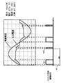
図15に、特許文献1に記載された従来の直流電源装置における入力電流・電圧波形の一例を示す。
FIG. 15 shows an example of input current / voltage waveforms in the conventional DC power supply device described in
また、特許文献1に記載の従来の直流電源装置は、インバータ回路38およびインバータ回路38により駆動される電動機39を負荷に備えており、インバータを制御するインバータ制御手段40におけるパルス幅変調制御信号のデューティ比に基いて短絡素子36の短絡開始タイミングおよび短絡時間を決定することで、負荷状態に応じて力率を改善することができる。
しかしながら、交流電源1の半周期毎に1回、交流電源1をリアクタ6を介して短絡する前記従来の構成では、負荷へ供給する直流電圧をさらに高くしようとする場合に、短絡
素子36の電流が増加することから、電流定格のより大きな短絡素子36を使用しなければならず、サイズアップやコストアップにつながってしまうとともに、直流電圧を高くするにつれて電流波形における正弦波状からの乖離が大きくなり、力率が低下してしまうという課題があった。
However, in the conventional configuration in which the
本発明は、上記従来の課題を解決するもので、軽負荷時における電源装置の効率を低下させることなく、低コストにて高力率かつ昇圧能力に優れた直流電源装置を提供することを目的とする。 SUMMARY OF THE INVENTION The present invention solves the above-described conventional problems, and an object of the present invention is to provide a DC power supply device that has a high power factor and excellent boosting capability at low cost without reducing the efficiency of the power supply device at light load. And
前記従来の課題を解決するために、本発明の直流電源装置は、交流電源の半周期毎に短絡素子(以下スイッチング手段と記す)を短絡動作させる回数を、負荷に応じて変更するものである。 In order to solve the above-described conventional problem, the DC power supply device of the present invention changes the number of times that the short-circuit element (hereinafter referred to as switching means) is short-circuited in accordance with the load every half cycle of the AC power supply. .
これによって、高い直流電圧を必要とする負荷を駆動する場合には、短絡回数を増加させることで、1回の短絡動作においてスイッチング手段に流れるピーク電流を増加させることなく、より正弦波に近い電流波形を得るとともに、昇圧能力を向上させるものである。 As a result, when driving a load that requires a high DC voltage, a current closer to a sine wave can be obtained by increasing the number of short circuits without increasing the peak current flowing through the switching means in one short circuit operation. The waveform is obtained and the boosting capability is improved.
また、軽負荷時には、短絡回数を少なくすることにより、直流電源装置におけるスイッチング損失を低減するものである。 Further, at the time of light load, the switching loss in the DC power supply device is reduced by reducing the number of short circuits.
また、本発明の直流電源装置は、直流電圧が目標電圧と等しくなるように、スイッチング手段の(短絡開始タイミングと短絡時間とからなる)短絡期間と短絡回数とを制御するものであり、かつ、短絡回数の上限値を負荷に応じて切り替えるものである。 The DC power supply device of the present invention controls the short-circuit period and the number of short-circuits (consisting of the short-circuit start timing and the short-circuit time) of the switching means so that the DC voltage becomes equal to the target voltage, and The upper limit value of the number of short circuits is switched according to the load.
これによって、直流電源装置の温度上昇に支障が生じない短絡回数以下の範囲において、スイッチング手段の短絡回数を、負荷状況に応じて選択することができる。 As a result, the number of short circuits of the switching means can be selected in accordance with the load condition within a range equal to or less than the number of short circuits that does not hinder the temperature rise of the DC power supply device.
また、本発明の直流電源装置は、短絡時間が予め定められた最大時間に等しくなっても直流電圧が目標電圧よりも低い場合にのみ短絡回数を増加させるものである。 The DC power supply device of the present invention increases the number of short circuits only when the DC voltage is lower than the target voltage even when the short circuit time is equal to a predetermined maximum time.
これにより、直流電源装置は、常に必要最低限の短絡回数にて動作させることができる。 Thereby, the DC power supply device can always be operated with the minimum number of short circuits.
本発明の直流電源装置は、交流電源の半周期毎に短絡動作させる短絡回数を、負荷に応じて変更することにより、高い直流電圧を必要とする負荷の場合に短絡回数を増加させることで、スイッチング手段に流れる電流のピーク値を増加させることなく、従来同等の電流容量のスイッチング素子を用いて入力電流をより正弦波に近い波形とすることができることから、低コストにて力率と昇圧能力の向上を両立することができる。 The DC power supply device of the present invention increases the number of short-circuits in the case of a load that requires a high DC voltage by changing the number of short-circuits to be short-circuited every half cycle of the AC power supply according to the load. Without increasing the peak value of the current flowing through the switching means, the input current can be made to have a waveform closer to a sine wave using a switching element having a current capacity equivalent to that of the conventional switching means. Can be improved at the same time.
また、高い直流電圧を必要としない負荷の場合には、短絡回数を少なくすることで、スイッチング損失を抑えることができ、直流電源装置の電力変換効率を高く保つことができる。 In the case of a load that does not require a high DC voltage, the switching loss can be suppressed by reducing the number of short circuits, and the power conversion efficiency of the DC power supply device can be kept high.
また、本発明の直流電源装置は、負荷に応じて短絡回数の上限値を切り替えることにより、温度上昇の制約範囲内で得られる昇圧能力の限界まで直流電源装置を利用することが可能となる。 In addition, the DC power supply device of the present invention can use the DC power supply device up to the limit of the boosting capability obtained within the temperature rise restriction range by switching the upper limit value of the number of short circuits according to the load.
また、本発明の直流電源装置は、交流電源の半周期間の短絡回数に上限値を設けて、予め設定された短絡時間の最大値に達しても直流電圧が目標電圧よりも低い場合にのみスイッチング手段の短絡回数を増やすことで、常に負荷に応じた必要最小限の短絡回数にて動作させることができるため、常に直流電源装置を最適な効率で動作させることができる。 In addition, the DC power supply device of the present invention provides an upper limit value for the number of short circuits during a half cycle of the AC power supply, and switches only when the DC voltage is lower than the target voltage even when the maximum value of the preset short circuit time is reached. By increasing the number of short-circuits of the means, it is possible to always operate with the minimum number of short-circuits corresponding to the load, and therefore it is possible to always operate the DC power supply device with optimum efficiency.
第1の発明は、交流電源からの交流電圧を直流電圧に整流して負荷に供給する整流手段と、互いに直列に接続されて、前記整流手段の直流出力端の両端間に接続され、倍電圧整流回路を構成する第1のコンデンサおよび第2のコンデンサと、交流電源と整流手段の一方の交流入力端との間に接続されたリアクタと、交流電源をリアクタを介して短絡するスイッチング手段と、交流電源のゼロクロス点を検出するゼロクロス検出手段とを備え、ゼロクロス点に同期させてスイッチング手段を短絡動作させる制御手段を有する直流電源装置において、交流電源の半周期毎に行うスイッチング手段の短絡回数を、負荷に応じて変更するものである。 A first aspect of the present invention is a rectifier that rectifies an AC voltage from an AC power source into a DC voltage and supplies it to a load, and is connected in series with each other and connected between both ends of a DC output end of the rectifier. A first capacitor and a second capacitor constituting a rectifier circuit, a reactor connected between the AC power source and one AC input terminal of the rectifier unit, switching means for short-circuiting the AC power source via the reactor, In a DC power supply apparatus having a control means for short-circuiting the switching means in synchronization with the zero-cross point, the number of short-circuits of the switching means performed every half cycle of the AC power supply is provided. , Change according to the load.
負荷が必要とする直流電源装置の昇圧能力に応じて、スイッチング手段の短絡回数を変更することにより、必要な場合にのみスイッチング手段の短絡回数を増加させることで、不要なスイッチング動作を削減することができ、より効率の高い状態で、所望の昇圧能力を得ることができる。 To reduce unnecessary switching operations by increasing the number of shorts of the switching means only when necessary by changing the number of shorts of the switching means according to the boosting capability of the DC power supply required by the load Thus, a desired boosting capability can be obtained in a more efficient state.
第2の発明は、第1の発明において、入力電流を検出する電流検出手段を備え、入力電流が大きくなるほどスイッチング手段の短絡回数を増加させることにより、高い昇圧能力を得るだけでなく、同時に力率を向上させることで、コンセントから取り出し得る最大電力を高くすることが可能となる。 According to a second invention, in the first invention, the current detection means for detecting the input current is provided. By increasing the number of short-circuits of the switching means as the input current increases, not only a high boosting capability is obtained, but simultaneously By increasing the rate, the maximum power that can be taken out from the outlet can be increased.
第3の発明は、第1の発明において、負荷としてインバータおよびインバータ駆動される電動機を有し、インバータ周波数が高くなるほどスイッチング手段の短絡回数を増加させることで、電動機の誘起電圧の増加に対応させて、必要な直流電圧が得られるように直流電源装置の昇圧能力を高めることが可能となる。 According to a third invention, in the first invention, an inverter and an electric motor driven by the inverter are provided as loads, and the number of short circuits of the switching means is increased as the inverter frequency is increased to cope with an increase in the induced voltage of the electric motor. Thus, the boosting capability of the DC power supply device can be increased so that the necessary DC voltage can be obtained.
第4の発明は、第1〜3のいずれか1つの発明において、電源周波数が50Hz時の短絡回数を60Hzの場合よりも多く設定することにより、同じ短絡回数では60Hzと比較してやや高力率が得られにくい50Hzにおいても、電源周波数が60Hzの場合と同等の力率を確保することが可能となる。 According to a fourth aspect of the present invention, in any one of the first to third aspects, by setting the number of short circuits when the power supply frequency is 50 Hz more than the case of 60 Hz, the same short circuit number is slightly higher than that of 60 Hz. Even at 50 Hz where it is difficult to obtain the power factor, a power factor equivalent to that when the power supply frequency is 60 Hz can be secured.
第5の発明は、交流電源からの交流電圧を直流電圧に整流して負荷に供給する整流手段と、互いに直列に接続されて、整流手段の直流出力端の両端間に接続され、倍電圧整流回路を構成する第1のコンデンサおよび第2のコンデンサと、交流電源と整流手段の一方の交流入力端との間に接続されたリアクタと、交流電源をリアクタを介して短絡するスイッチング手段と、交流電源のゼロクロス点を検出するゼロクロス検出手段と、ゼロクロス点に同期させてスイッチング手段を短絡動作させる制御手段と、負荷へ供給される直流電圧を検出する電圧検出手段とを備え、制御手段は、直流電圧が予め定められた目標電圧に等しくなるように、スイッチング手段の短絡開始タイミングおよび短絡時間を調整する直流電源装置において、負荷に応じて短絡回数の上限値を切り替えることにより、常に負荷に必要な直流電圧を得るのに必要最低限の短絡回数以下で動作させることができるため、交流電源の電圧が想定外に低下した場合においても、短絡回数の急増によって直流電源装置の温度が上昇するのを防止することができる。 According to a fifth aspect of the present invention, there is provided a rectifying unit that rectifies an AC voltage from an AC power source into a DC voltage and supplies the DC voltage to a load, and is connected in series with each other and connected between both ends of the DC output end of the rectifying unit. A first capacitor and a second capacitor constituting a circuit; a reactor connected between the AC power supply and one AC input terminal of the rectifying means; a switching means for short-circuiting the AC power supply through the reactor; A zero cross detection means for detecting a zero cross point of the power supply, a control means for short-circuiting the switching means in synchronization with the zero cross point, and a voltage detection means for detecting a DC voltage supplied to the load, the control means is a direct current In a DC power supply device that adjusts the short-circuit start timing and short-circuit time of the switching means so that the voltage becomes equal to a predetermined target voltage, according to the load By switching the upper limit of the number of short-circuits, it is possible to always operate below the minimum number of short-circuits necessary to obtain the DC voltage required for the load, so even when the voltage of the AC power supply falls unexpectedly, It is possible to prevent the temperature of the DC power supply device from rising due to a rapid increase in the number of short circuits.
第6の発明は、第5の発明において、入力電流を検出する電流検出手段を備え、入力電流が大きくなるほどスイッチング手段の短絡回数の上限値を多く設定することにより、高
い昇圧能力を得られるとともに、力率を向上させて、コンセントから取り出し得る最大電力を高くすることができる。
According to a sixth aspect of the present invention, in the fifth aspect of the invention, the current detection means for detecting the input current is provided, and the higher the input current, the higher the upper limit value of the number of short-circuits of the switching means. By increasing the power factor, the maximum power that can be taken out from the outlet can be increased.
第7の発明は、第5の発明において、負荷としてインバータおよびインバータ駆動される電動機を有し、インバータ周波数が高くなるほどスイッチング手段の短絡回数の上限値を多く設定することで、電動機の誘起電圧の増加に対応して、直流電源装置の昇圧能力を高くすることができる。 According to a seventh invention, in the fifth invention, an inverter and an inverter-driven electric motor are provided as loads, and the upper limit value of the number of short-circuits of the switching means is set higher as the inverter frequency becomes higher. Corresponding to the increase, the boosting capability of the DC power supply device can be increased.
第8の発明は、第5の発明において、周囲温度によって短絡回数の上限値を変更することで、特に低温時に短絡回数の上限値を引き上げることで、直流電源装置の温度上昇限界まで昇圧性能を最大限に引き出すことが可能となる。 According to an eighth aspect of the present invention, in the fifth aspect, by changing the upper limit value of the number of short circuits depending on the ambient temperature, the boost performance is increased to the temperature rise limit of the DC power supply device by raising the upper limit value of the number of short circuits particularly at low temperatures. It can be pulled out to the maximum.
第9の発明は、第5の発明において、電源周波数が50Hz時の短絡回数を60Hzの場合よりも多く設定することにより、60Hzと比較して相対的に高力率がやや得られにくい50Hzにおいても、電源周波数が60Hzの場合と同等の力率を確保することが可能となる。 According to a ninth aspect, in the fifth aspect, by setting the number of short-circuits when the power supply frequency is 50 Hz to be higher than that in the case of 60 Hz, a relatively high power factor is relatively difficult to obtain compared to 60 Hz at 50 Hz. Also, it becomes possible to ensure a power factor equivalent to that when the power supply frequency is 60 Hz.
第10の発明は、第5の発明において、すべての短絡時間が、スイッチング手段の短絡開始タイミング毎に予め設定された所定の短絡時間の最大値に等しくなっても直流電圧が目標電圧よりも低い場合に、短絡回数を増加させることにより、負荷が必要とする直流電圧を出すのに最も少ない短絡回数にて動作させることができるので、常に効率のよい状態で動作させることが可能となる。 According to a tenth aspect, in the fifth aspect, the DC voltage is lower than the target voltage even when all the short-circuit times are equal to a maximum value of a predetermined short-circuit time preset for each short-circuit start timing of the switching means. In this case, by increasing the number of short-circuits, it is possible to operate with the shortest number of short-circuits to output the DC voltage required by the load, so it is possible to always operate in an efficient state.
第11の発明は、第5の発明において、電圧検出手段において検出される直流電圧が予め目標電圧記憶手段によって設定された目標電圧に比べて低い場合に、動作中の制御モードにおける短絡回数以上の制御モードでのみ短絡動作される短絡時間twj(n+1≦j≦m)を増加させると同時に、動作中の制御モードよりも短絡回数の低い制御モードにおいても短絡動作される短絡時間twi(1≦i≦n)の一部またはすべてを減少させることにより、短絡回数の異なる各制御モード間において、短絡時間の最大値twimaxの大小関係に縛られずに自由に設定することができるため、各制御モードにおいて、力率および高調波の観点から最良の電流波形を生成することができ、かつ、各制御モード間において電流波形を滑らかに連続的に切り替えることが可能となる。 In an eleventh aspect based on the fifth aspect, when the DC voltage detected by the voltage detecting means is lower than the target voltage set in advance by the target voltage storing means, the number of short circuits in the operating control mode is greater than or equal to The short circuit time twi (1 + 1 ≦ j ≦ m) in which the short circuit operation is performed only in the control mode is increased, and at the same time, the short circuit time twi (1) in the control mode in which the number of short circuits is lower than the control mode in operation. By reducing a part or all of ≦ i ≦ n), each control mode having a different number of short circuits can be freely set without being restricted by the magnitude relationship of the maximum value twimax of the short circuit time. In the mode, the best current waveform can be generated from the viewpoint of power factor and harmonics, and the current waveform is smoothly and continuously switched between control modes. It is possible to change to become.
第12の発明は、第11の発明において、すべての短絡時間twj(n+1≦j≦m)が短絡開始タイミング毎に予め設定された最大時間twjmax(n+1≦j≦m)に等しくなっても前記直流電圧が目標電圧よりも低い場合に、前記短絡回数を増加させることにより、負荷が必要とする直流電圧を出すのに最も少ない短絡回数にて動作させることができるので、常に効率のよい状態で動作させることが可能となる。 In a twelfth aspect according to the eleventh aspect, all short-circuiting times twj (n + 1 ≦ j ≦ m) are equal to a maximum time twjmax (n + 1 ≦ j ≦ m) preset at each short-circuit start timing. Even when the DC voltage is lower than the target voltage, the number of short circuits can be increased to increase the number of short circuits. It is possible to operate in a good condition.
第13の発明は、第1〜12のいずれか1つの発明において、電源の半周期に1回スイッチング手段を短絡する運転状態(制御モード)を有することにより、高い直流電圧を必要としない負荷範囲において、短絡回数増による直流電源装置の効率低下を防ぎ、従来同等の効率を確保することができる
第14の発明は、第1〜13のいずれか1つの発明において、電源の半周期に1度もスイッチング手段を短絡しない制御モードを有することにより、不要な昇圧動作を抑えることができるため、特に交流電源電圧が高い場合に、負荷が要求する以上に直流電圧を上げて全体の効率を低下させるのを防止することができる。
In a thirteenth aspect of the invention, in any one of the first to twelfth aspects, a load range that does not require a high DC voltage by having an operating state (control mode) in which the switching means is short-circuited once in a half cycle of the power source. In the present invention, the efficiency of the DC power supply device can be prevented from decreasing due to an increase in the number of short-circuits, and the same efficiency can be ensured. In addition, since it has a control mode that does not short-circuit the switching means, unnecessary boosting operation can be suppressed. Therefore, especially when the AC power supply voltage is high, the DC voltage is raised more than required by the load to lower the overall efficiency. Can be prevented.
また第15の発明は、第1〜14のいずれか1つの発明において、電源半周期の前半に2回、主に昇圧能力向上に寄与する1回目および2回目の短絡期間と、後半に1回、主に
力率を向上させる3回目の短絡期間とによってスイッチング手段を間欠短絡する制御モードを有することにより、スイッチング損失が少なく、高調波の高次成分の小さな入力電流波形を得ることができる。
The fifteenth invention is the invention according to any one of the first to fourteenth inventions, which is twice in the first half of the power supply half cycle, first and second short-circuit periods mainly contributing to boosting capability improvement, and once in the second half. By having a control mode in which the switching means is intermittently short-circuited mainly by the third short-circuit period for improving the power factor, it is possible to obtain an input current waveform with small switching loss and a high-order harmonic component.
このため、スイッチング手段の短絡開始タイミングや短絡時間に対して細かな制御を行わなくても高調波規制に対して十分なマージンを得ることができるため、短絡期間の制御をより簡単なものにすることができる。
以下、本発明の実施の形態について、図面を参照しながら説明する。なお、この実施の形態によって本発明が限定されるものではない。
For this reason, a sufficient margin for harmonic regulation can be obtained without performing fine control on the short-circuit start timing and the short-circuit time of the switching means, thereby making the control of the short-circuit period easier. be able to.
Hereinafter, embodiments of the present invention will be described with reference to the drawings. Note that the present invention is not limited to the embodiments.
(実施の形態1)
図1は、本発明の第1の実施の形態における直流電源装置の構成を示すものである。
(Embodiment 1)
FIG. 1 shows the configuration of a DC power supply device according to a first embodiment of the present invention.
図1に示すように、本発明の直流電源装置は、交流電源1の交流電圧を整流する整流回路2と、整流回路2の一方の交流入力端から整流回路2の各々の直流出力端との間にそれぞれ接続された第1のコンデンサ3、第2のコンデンサ4を備えており、整流回路2と、互いに直列に接続された第1のコンデンサ3と第2のコンデンサ3とによって倍電圧整流回路を構成し、負荷5へ直流電圧を供給している。
As shown in FIG. 1, the DC power supply device of the present invention includes a rectifier circuit 2 that rectifies an AC voltage of an
さらに、交流電源1と整流回路2の交流入力端との間にはリアクタ6が接続され、交流電源1がリアクタ6を介して短絡されるように、ダイオードブリッジやMOSFET・IGBTなどから構成される双方向性のスイッチング手段7が設けられる。
Further, a
また、交流電源1の両端には、交流電源1のゼロクロス点を検出するゼロクロス検出手段8が接続されており、マイコン等で構成される制御手段9内に設けられた駆動信号生成手段9aにおいて、ゼロクロス検出手段8にて検出されたゼロクロス点に同期させて、スイッチング手段7を駆動する駆動信号を生成し、スイッチング素子駆動手段10へ駆動信号を伝えてスイッチング手段7を間欠短絡する。
Moreover, the zero cross detection means 8 for detecting the zero cross point of the
なお、本実施の形態では図示していないが、整流回路2の直流出力端子間にさらに平滑コンデンサを設けてもよい。 Although not shown in the present embodiment, a smoothing capacitor may be further provided between the DC output terminals of the rectifier circuit 2.
本実施の形態1における直流電源装置は、スイッチング手段7の駆動パターンにおいて交流電源1の半周期における短絡回数の異なる2つの制御モードを有する。
The DC power supply device according to the first embodiment has two control modes in which the number of short circuits in the half cycle of the
第1の制御モードは、交流電源1の半周期毎に2回、スイッチング手段7を短絡するもので、ゼロクロス点から予め定められた一定の時間td1およびtd2経過後にそれぞれスイッチング手段7を一定期間tw1、tw2だけ短絡し、その後開放する。
In the first control mode, the switching means 7 is short-circuited twice every half cycle of the
図2に本実施の形態における第1の制御モード時の入力電流・電圧波形を示す。 FIG. 2 shows input current / voltage waveforms in the first control mode according to the present embodiment.
図2の例は、電源電圧100V、入力1540W、直流電圧274Vにおけるもので、力率0.98が得られている。図10に示した、スイッチング手段7のピーク電流がほぼ等しい従来の電流波形(力率0.965)と比べても、入力電流の通電幅が広がることで高い力率が得られることがわかる。 The example of FIG. 2 is for a power supply voltage of 100 V, an input of 1540 W, and a DC voltage of 274 V, and a power factor of 0.98 is obtained. Compared with the conventional current waveform (power factor 0.965) in which the peak current of the switching means 7 is substantially equal as shown in FIG. 10, it can be seen that a high power factor can be obtained by widening the conduction width of the input current.
第2の制御モードは、交流電源1の半周期毎に5回、スイッチング手段7を短絡するものである。
In the second control mode, the switching means 7 is short-circuited five times every half cycle of the
図3(a)に本実施の形態における第2の制御モード時の入力電流・電圧波形を、図3(b)に第2の制御モード時の入力電流の高調波電流成分を示す。 FIG. 3A shows an input current / voltage waveform in the second control mode in the present embodiment, and FIG. 3B shows a harmonic current component of the input current in the second control mode.
図3の例では、電源電圧100V、入力1925W、直流電圧312Vにおいて、力率約0.98が得られており、昇圧能力および力率の点で、第1の制御モードに比べて有利な電流波形を得られることがわかる。 In the example of FIG. 3, a power factor of about 0.98 is obtained at a power supply voltage of 100 V, an input of 1925 W, and a DC voltage of 312 V, which is an advantageous current compared to the first control mode in terms of boosting capability and power factor. It can be seen that the waveform can be obtained.
なお、上記第1および第2の制御モードの選択は、同じく制御手段9内に備えられた短絡回数選択手段9bによって行われる。 The selection of the first and second control modes is performed by the short-circuit number selection means 9b provided in the control means 9 as well.
以下に、短絡回数選択手段9bの動作について説明を行う。
Hereinafter, the operation of the short circuit
本発明の直流電源装置は、予め駆動される負荷毎に目標電圧が定められており、これを記憶する目標電圧記憶手段9cを備えている。 The DC power supply device of the present invention has a target voltage for each load that is driven in advance, and includes target voltage storage means 9c for storing the target voltage.
直流電源装置が駆動する負荷が、高い直流電圧を必要とする場合には、負荷に応じて目標電圧記憶手段9cに記憶されている、負荷の駆動に必要な電圧が目標電圧とされる。
When the load driven by the DC power supply device requires a high DC voltage, the voltage necessary for driving the load stored in the target
さらに、短絡回数選択手段9bは、高い直流電圧を出力するのに適した第2の制御モードを選択し、駆動信号生成手段9aに選択した制御モードを伝達する。 Further, the short circuit number selection means 9b selects a second control mode suitable for outputting a high DC voltage, and transmits the selected control mode to the drive signal generation means 9a.
また、軽負荷で、特に高い直流電圧の必要がない場合には、目標電圧記憶手段9cに記憶されている、倍電圧整流回路をベースとする本直流電源装置にとって変換効率がよいDC250V前後の電圧が、目標電圧として選択される。 When the load is light and there is no need for a particularly high DC voltage, the voltage stored in the target voltage storage means 9c is a voltage around DC 250V, which has good conversion efficiency for the DC power supply device based on the voltage doubler rectifier circuit. Is selected as the target voltage.
さらに、短絡回数選択手段9bは、さほど昇圧能力が必要ない負荷であることから、効率を優先して第1の制御モードを選択し、駆動信号生成手段9aに選択した制御モードを伝達する。 Furthermore, since the number of short-circuit selection means 9b is a load that does not require much boosting capability, the first control mode is selected with priority on efficiency, and the selected control mode is transmitted to the drive signal generation means 9a.
次に、本発明の直流電源装置における駆動信号生成手段9aでの駆動信号の生成方法について以下に記載する。 Next, a method for generating a drive signal in the drive signal generating means 9a in the DC power supply device of the present invention will be described below.
本発明の直流電源装置は、負荷5に並列に接続されて、負荷5に供給される直流電圧を検出する電圧検出手段11を備えている。
The DC power supply device of the present invention includes voltage detection means 11 that is connected in parallel to the
駆動信号生成手段aは、短絡回数選択手段9bより選択された制御モードが第1の制御モードの場合には、tdi(1≦i≦2)を固定とし、電圧検出手段11における検出電圧と、目標電圧記憶手段9cによって予め記憶された目標電圧とを比較手段9dによって比較し、負荷5へ供給される直流電圧が目標電圧に等しくなるように、スイッチング手段7の短絡時間twi(1≦i≦2)の値を増減する。
When the control mode selected by the short circuit
また、短絡回数選択手段9bにて選択された制御モードが第2の制御モードの場合には、同じくtdi(1≦i≦5)を固定とし、電圧検出手段11における検出電圧と目標電圧記憶手段9cによって予め記憶された目標電圧とを比較手段9dによって比較し、負荷へ供給される直流電圧が目標電圧に等しくなるように、スイッチング手段7の短絡時間twi(1≦i≦5)の値を増減する。
When the control mode selected by the short circuit
なお、図3(b)に示すように、電源半周期におけるスイッチング手段の間欠短絡回数が多くなるにつれて、入力電流における15次〜25次付近の高調波成分は大きくなる傾向がある。 As shown in FIG. 3B, the harmonic components near the 15th to 25th orders in the input current tend to increase as the number of intermittent shorts of the switching means in the half cycle of the power supply increases.
したがって、一般的に短絡回数の増加は、高調波規制の面で不利になりやすいこと、またスイッチング手段7におけるスイッチング損失が増加することから、スイッチング手段7の短絡回数は、必要以上に多くしないことが望ましい。 Therefore, in general, an increase in the number of short circuits tends to be disadvantageous in terms of harmonic regulation, and a switching loss in the switching means 7 increases, so the number of short circuits in the switching means 7 should not be increased more than necessary. Is desirable.
以上のように、本発明の直流電源装置は、負荷5が高い直流電圧を必要としない場合、目標電圧を低く設定し、第1の制御モードにて動作することによって、必要以上にスイッチング回数を増やさず、高効率動作させることができる。
As described above, when the
また、負荷5が高い直流電圧を必要とする場合には、目標電圧を高く設定し、第2の制御モードを採用することにより、高力率にて高い直流電圧を得ることが可能となる。
Moreover, when the
なお、本実施の形態では、ゼロクロス点からi番目の短絡開始タイミングtdiの値を負荷の状態によらず固定としたが、負荷6によってtdiの値を最適な入力電流波形となるように変更してもよい。
In this embodiment, the value of the i-th short-circuit start timing tdi from the zero cross point is fixed regardless of the state of the load. However, the value of tdi is changed by the
例えば、入力電流の検出手段を設けて入力電流の大きさによってtdiを変更してもよいし、負荷に電動機を有する場合には、電動機の回転数や、電動機を駆動するインバータの周波数などに応じてtdiを変更してもよい。 For example, an input current detection means may be provided to change tdi depending on the magnitude of the input current. When a load has an electric motor, it depends on the rotation speed of the electric motor, the frequency of the inverter that drives the electric motor, etc. Tdi may be changed.
また、本実施の形態では、電圧検出手段11を備えて、負荷の状態に応じて定められた目標電圧となるように電圧フィードバックを行ってi番目の短絡期間における短絡時間twiを変更しているが、負荷に応じて短絡回数(電源半周期にk回)と、tdiおよびtwi(1≦i≦k)からなるスイッチング手段7の駆動パターンを予め記憶しておき、直流電圧によらず、駆動する負荷に応じて予め記憶した駆動パターンにてスイッチング手段7を間欠短絡動作させてもよい。 In the present embodiment, the voltage detection means 11 is provided, and the voltage feedback is performed so that the target voltage is determined according to the state of the load to change the short circuit time twi in the i-th short circuit period. However, according to the load, the number of short circuits (k times in the half cycle of the power supply) and the drive pattern of the switching means 7 consisting of tdi and twi (1 ≦ i ≦ k) are stored in advance. The switching means 7 may be intermittently short-circuited with a drive pattern stored in advance according to the load to be performed.
(実施の形態2)
本発明の第2の実施の形態の直流電源装置の構成は、図1に示した実施の形態1と同じであり、説明を省略する。
(Embodiment 2)
The configuration of the DC power supply device according to the second embodiment of the present invention is the same as that of the first embodiment shown in FIG.
本実施の形態の直流電源装置は、実施の形態1と同様に、スイッチング手段7の駆動パターンにおいて短絡回数の異なる2つの制御モードを有する。 As in the first embodiment, the DC power supply device of the present embodiment has two control modes with different numbers of short circuits in the drive pattern of the switching means 7.
第1および第2の制御モードでは、スイッチング手段7の電流や温度が最大定格を越えないように、それぞれのモード毎に、i番目の短絡期間における短絡時間twi(以降短絡時間twiと記す)の最大値twimaxが設けられている。 In the first and second control modes, the short-circuit time twi in the i-th short-circuit period (hereinafter referred to as short-circuit time twi) is set for each mode so that the current and temperature of the switching means 7 do not exceed the maximum rating. A maximum value twimax is provided.
図1に示すように、本発明の直流電源装置には、負荷5へ供給される直流電圧を検出する電圧検出手段11が設けられ、電圧検出手段11で得られた検出電圧は、比較手段9dによって、予め目標電圧記憶手段9cによって設定された目標電圧と比較され、検出電圧が目標電圧よりも低い場合には、スイッチング手段7の短絡時間twiを大きくし、検出電圧が目標電圧よりも高い場合には、スイッチング手段7の短絡時間twiを小さくする。
As shown in FIG. 1, the DC power supply apparatus of the present invention is provided with voltage detection means 11 for detecting a DC voltage supplied to the
このように、負荷5へ供給される直流電圧が所望の目標電圧となるように、駆動信号生成手段9aによって、スイッチング手段7の短絡時間twiが調整される。
In this way, the short-circuit time twi of the switching means 7 is adjusted by the drive signal generating means 9a so that the DC voltage supplied to the
次に、短絡回数選択手段9bにおける制御モードの決定方法について以下に説明する。
Next, a method for determining the control mode in the short circuit
電源投入時やリセット時においては、負荷5は無負荷またはそれに近い軽負荷であることが想定されることから、高い直流電圧を必要としない。そのため、短絡回数が少なく、効率に優れる第1の制御モード(短絡回数は2回)が選択される。
At the time of power-on or reset, it is assumed that the
この時、短絡時間twi(1≦i≦2)の初期値はいずれも0にセットされて、直流電源装置の回路構成は、倍電圧整流回路そのものとなる。 At this time, the initial values of the short circuit time twi (1 ≦ i ≦ 2) are all set to 0, and the circuit configuration of the DC power supply device is the voltage doubler rectifier circuit itself.
以降の第1の制御モードにおける短絡時間twiの増減および制御モードの選択に関するフローチャートを図4(a)に、第2の制御モードにおける短絡時間twiの増減および制御モードの選択に関するフローチャートを図4(b)に示す。 FIG. 4A is a flowchart regarding the increase / decrease of the short circuit time twi and the selection of the control mode in the first control mode, and FIG. 4A is a flowchart regarding the increase / decrease of the short circuit time twi and the selection of the control mode in the second control mode. Shown in b).
図4(a)に示すように、第1の制御モードにおいては、短絡時間tw1またはtw2がそれぞれ所定の値tw1max、tw2maxに達してもなお目標電圧に満たない場合に第2の制御モードを選択し、第2の制御モード(短絡回数は5回)へと移行する。 As shown in FIG. 4A, in the first control mode, the second control mode is selected when the short-circuit time tw1 or tw2 reaches the predetermined values tw1max and tw2max, respectively, but still does not reach the target voltage. Then, the process shifts to the second control mode (the number of short circuits is 5).
また、第2の制御モードにおいては、第1の制御モードから第2の制御モードへの移行時に新たに増えた短絡期間における短絡時間twi(3≦i≦5)のいずれかまたはすべてがゼロとなっても電圧検出手段11にて検出される負荷5への供給電圧が目標電圧よりも高い場合に、第1の制御モードへ移行する。
Further, in the second control mode, any or all of the short circuit time twi (3 ≦ i ≦ 5) in the short circuit period newly increased at the time of transition from the first control mode to the second control mode is zero. Even when the voltage supplied to the
以上の制御により、本実施の形態の直流電源装置は、負荷5に必要な直流電圧を得るために必要最低限の短絡回数で動作させることができるため、常に効率のよい動作が可能となる。
With the above control, the direct-current power supply device of the present embodiment can be operated with the minimum number of short-circuits required to obtain the direct-current voltage required for the
なお、本実施の形態においては、2つの制御モードにて、交流電源1の半周期間におけるスイッチング手段7の短絡回数を2回および5回の2段階にて切換を行っているが、3段階以上の制御モードを設けて、よりきめ細かに短絡回数についての切替制御を行ってももちろんよい。
In the present embodiment, the number of short circuits of the switching means 7 during the half cycle of the
(実施の形態3)
図5は、第3の実施の形態における直流電源装置の構成を示すものである。
(Embodiment 3)
FIG. 5 shows a configuration of a DC power supply device according to the third embodiment.
図5に示すように、本発明の直流電源装置は、交流電源1の交流電圧を整流する整流回路2と、整流回路2の一方の交流入力端から整流回路2の各々の直流出力端との間にそれぞれ接続された第1のコンデンサ3、第2のコンデンサ4を備えており、整流回路2と、互いに直列に接続された第1のコンデンサ3と第2のコンデンサ3とによって倍電圧整流回路を構成し、負荷5へ直流電圧を供給している。
As shown in FIG. 5, the DC power supply device of the present invention includes a rectifier circuit 2 that rectifies the AC voltage of the
さらに、交流電源1と整流回路2の交流入力端との間にはリアクタ6が接続され、交流電源1がリアクタ6を介して短絡されるように、双方向性のスイッチング手段7が設けられる。
Furthermore, a
また、交流電源1の両端には、交流電源1のゼロクロス点を検出するゼロクロス検出手段8が接続されており、マイコン等で構成されるコンバータ制御手段9eにおいて、ゼロクロス検出手段8にて検出されたゼロクロス点に同期させて、スイッチング手段7を駆動する駆動信号を生成し、スイッチング素子駆動手段10へ駆動信号を伝えてスイッチング手段7を間欠短絡する。
Moreover, the zero cross detection means 8 which detects the zero cross point of the
さらに、本実施の形態における直流電源装置は、交流電源1からの入力電流を検出する電流検出手段13を備えている。
Further, the DC power supply device in the present embodiment includes current detection means 13 that detects an input current from the
本発明の直流電源装置は、実施の形態1または2と同様に、電源半周期間におけるスイッチング手段の短絡回数が異なる複数の制御モードを有しており、電流検出手段13によって検出される入力電流に応じて、制御モード、すなわち交流電源1の半周期における短絡回数を以下のように決定する。
The DC power supply device of the present invention has a plurality of control modes in which the number of short-circuits of the switching means in the half cycle of the power supply is different as in the first or second embodiment, and the input current detected by the current detection means 13 Accordingly, the number of short circuits in the control mode, that is, the half cycle of the
コンバータ制御手段9eは、電流検出手段13によって検出される入力電流が低い場合には、電源装置の変換効率を優先した動作とするために、スイッチング損失が少なくなるように、短絡回数のより少ない制御モードを選択する。
When the input current detected by the
また、入力電流が大きくなり、コンセント容量に近づいた場合には、コンセントから取り出しうる電力が力率によって制限されることを鑑み、コンバータ制御手段9eは、力率の向上を優先した動作とするために、短絡回数のより多い制御モードを選択する。 Further, when the input current becomes large and the outlet capacity is approached, the converter control means 9e takes the priority on the improvement of the power factor in view of the fact that the power that can be taken out from the outlet is limited by the power factor. In addition, a control mode having a larger number of short circuits is selected.
以上の制御により、本実施の形態の直流電源装置は、入力電流の低い通常時には高い効率で動作することができ、またコンセント容量に近い入力電流付近では、高力率動作によってコンセントから取り出しうる最大電力を従来よりも大きくすることが可能となる。 With the above control, the DC power supply device of the present embodiment can operate with high efficiency at normal times when the input current is low, and the maximum power that can be taken out from the outlet by high power factor operation near the input current close to the outlet capacity. It becomes possible to make electric power larger than before.
(実施の形態4)
図6に本発明における第4の実施の形態の直流電源装置の構成を示す。
(Embodiment 4)
FIG. 6 shows the configuration of a DC power supply device according to a fourth embodiment of the present invention.
図6において、直流電源装置の構成は、実施の形態1〜3と同様であり、インバータ17およびインバータ17にて駆動される電動機18が、電源装置の負荷として接続されている。
In FIG. 6, the configuration of the DC power supply device is the same as in the first to third embodiments, and an
コンバータ制御手段9eは、インバータ17を駆動するインバータ制御手段19によって得られるインバータ周波数を検出し、インバータ周波数が高いほど、インバータ17へ供給する直流電圧の目標電圧を高く設定し、交流電源1の半周期におけるスイッチング手段7の短絡回数を多く設定する。
The converter control means 9e detects the inverter frequency obtained by the inverter control means 19 for driving the
なお、インバータ周波数の上昇に対して、目標電圧の設定と短絡回数は必ずしも同時に変更されるものではなく、場合によっては、短絡回数が同じで目標電圧のみ異なってもよいし、目標電圧が同じで短絡回数のみ異なってもよい。 Note that the setting of the target voltage and the number of short circuits are not necessarily changed at the same time as the inverter frequency increases. In some cases, the number of short circuits may be the same and only the target voltage may be different, or the target voltage may be the same. Only the number of short circuits may be different.
負荷5として接続される電動機18は、従来の直流電源装置を用いて駆動する場合に比べて、そのコイル巻線のターン数を増加することができる。
The
すなわち、電動機18のコイル巻数を増加させた場合、特に電動機18の高速域において、誘起電圧の上昇に対応するだけの高い直流電圧が必要となるが、本実施の形態の直流電源装置では、高速域において短絡回数の多い制御モードを採用することで、これに対応することができる。
That is, when the number of coil turns of the
また、運転頻度の比較的高い、電動機18の中速域においては、効率を重視して短絡回数の少ない制御モードを採用することで、従来同等の高いコンバータ効率を維持することができる。
Further, in the middle speed range of the
したがって、中速域においては、電動機18の巻数アップによって得られるインバータ損失の低減効果が得られ、かつ、その前段であるコンバータ効率を維持できることから、トータルとして電動機18の高効率駆動を実現することができる。
Therefore, in the medium speed range, the effect of reducing the inverter loss obtained by increasing the number of turns of the
(実施の形態5)
本発明における第5の実施の形態の直流電源装置の構成は、図1に示した実施の形態1に同じであるため、説明を省略する。
(Embodiment 5)
The configuration of the DC power supply device according to the fifth embodiment of the present invention is the same as that of the first embodiment shown in FIG.
制御手段9は、最もスイッチング手段の短絡回数の少ない直流電源装置の制御モードとして、従来の直流電源装置と同様に電源半周期の前半に1回だけ短絡する第1の制御モードを有しており、高い昇圧能力が必要な場合にのみ、第2の制御モードとして、短絡回数を5回に引き上げる。 The control means 9 has a first control mode for short-circuiting only once in the first half of the power supply half cycle as in the conventional DC power supply apparatus, as the control mode of the DC power supply apparatus having the shortest number of short circuits of the switching means. Only when a high boosting capability is required, the number of short circuits is increased to 5 as the second control mode.
なお、短絡回数の変更は、実施の形態2で示したように、スイッチング手段7の短絡時間twiが短絡時間の最大値twimaxに到達しても電圧検出手段11で検出される直流電圧が目標電圧に満たない場合に、第1の制御モードから第2の制御モードへ移行して短絡回数1回から5回に変更する。
Note that, as shown in the second embodiment, the number of short-circuits can be changed by changing the DC voltage detected by the
本実施の形態においては、昇圧性能が必要な場合にスイッチング手段7の短絡回数を増加させることで、最大出力電圧を高くすることができるとともに、従来の直流電源装置における出力電圧範囲内で負荷5を駆動する際には、スイッチング手段7の短絡回数が1回である従来の直流電源装置と全く同じ動作となるため、従来の直流電源装置と等しい効率を維持することができる。
In the present embodiment, when the boosting performance is required, the maximum output voltage can be increased by increasing the number of short circuits of the switching means 7, and the
(実施の形態6)
本発明における第6の実施の形態の直流電源装置の構成は、図1に示す実施の形態1と同じであるため、省略する。
(Embodiment 6)
The configuration of the DC power supply according to the sixth embodiment of the present invention is the same as that of the first embodiment shown in FIG.
本実施の形態の直流電源装置は、最もスイッチング手段7の短絡回数の少ない直流電源装置の制御モードとして、電源半周期の前半に1回だけ短絡する第1の制御モードを有しており、高い昇圧能力が必要な場合にのみ、複数の短絡回数を有する第2の制御モードへ移行する。 The DC power supply device of the present embodiment has a first control mode in which a short circuit is performed only once in the first half of the power supply half cycle as a control mode of the DC power supply device with the shortest number of short circuits of the switching means 7. Only when the boosting capability is required, the mode shifts to the second control mode having a plurality of short-circuit times.
第2の制御モードにおける短絡回数は、交流電源1の電源周波数によって異なり、50Hzの時には6回に、60Hzの時には5回に設定される。
The number of short circuits in the second control mode differs depending on the power supply frequency of the
スイッチング手段7の1回の短絡動作で改善できる通電幅は、スイッチング素子7の電流容量の関係から制限され、その改善効果は、リアクタ6、第1のコンデンサ3、第2のコンデンサ4の定数にてほぼ決まる。
The energization width that can be improved by one short-circuit operation of the switching means 7 is limited by the relationship of the current capacity of the
しかしながら、電源周波数50Hzの場合には、60Hzに比べて電源周期が長くなる。したがって、同じ短絡回数で比較した場合、電源周波数が50Hzの場合には、60Hzに比べて力率を確保する上で若干不利となる。 However, when the power frequency is 50 Hz, the power cycle is longer than that of 60 Hz. Therefore, when compared with the same number of short circuits, when the power supply frequency is 50 Hz, it is slightly disadvantageous in securing the power factor compared to 60 Hz.
図7(a)は、電源周波数50Hzで短絡回数を5回とした場合の入力電流波形を、図7(b)は、電源周波数50Hzで短絡回数を6回とした場合の入力電流波形を示す。 FIG. 7A shows an input current waveform when the power supply frequency is 50 Hz and the number of short circuits is 5 times, and FIG. 7B shows an input current waveform when the power supply frequency is 50 Hz and the number of short circuits is 6 times. .
図7(a)に示すように、入力電圧100V、直流電圧300V時において、交流電源1の半周期間における短絡回数を5回とした場合には、電源周波数50Hz時には、力率が約0.97となるが、図7(b)に示すように短絡回数を6回とすることで電源周波数60Hz時の力率と同程度の約0.98の力率が得られることがわかる。
As shown in FIG. 7A, when the number of short-circuits in the half cycle of the
したがって、本実施の形態の直流電源装置は、50Hzの場合に、60Hzの場合よりも短絡回数を多くすることによって60Hzの場合と同等の力率を得ることができる。 Therefore, the direct-current power supply device according to the present embodiment can obtain a power factor equivalent to that in the case of 60 Hz by increasing the number of short-circuits in the case of 50 Hz than in the case of 60 Hz.
(実施の形態7)
本発明における第7の実施の形態の直流電源装置の構成は、図5に示す実施の形態3と同じであるため、省略する。
(Embodiment 7)
The configuration of the DC power supply device according to the seventh embodiment of the present invention is the same as that of the third embodiment shown in FIG.
本実施の形態の直流電源装置は、短絡回数の異なる3つの制御モードを有しており、電圧検出手段11で検出された直流電圧が予め定められた目標電圧となるように、交流電源1の半周期毎に1回だけスイッチング手段7を短絡する第1の制御モードと、交流電源1の半周期の前半に2回、後半に1回スイッチング手段を短絡させる短絡時間をそれぞれ調整する第2の制御モードと、交流電源1の半周期毎に5回スイッチング手段7を短絡する第3の制御モードとを有する。
The DC power supply device of the present embodiment has three control modes with different numbers of short circuits, and the
図8(a)に本発明における第6の実施の形態の直流電源装置の第2の制御モード時の入力電流・電圧波形を、図8(b)に入力電流の高調波成分を示す。 FIG. 8A shows an input current / voltage waveform in the second control mode of the DC power supply according to the sixth embodiment of the present invention, and FIG. 8B shows harmonic components of the input current.
図8(a)は、間欠短絡回数を3回とすることで、入力電圧100V、入力1840W、直流電圧300V時において、力率0.97を実現した例である。 FIG. 8A shows an example in which a power factor of 0.97 is realized at an input voltage of 100 V, an input of 1840 W, and a DC voltage of 300 V by setting the number of intermittent shorts to three.
交流電源1の半周期の前半の2回は、スイッチング手段7の電流ピークが高く、リアクタ6に貯えられる電磁エネルギーも大きいことから、主に直流電圧の昇圧に寄与し、後半の1回は、入力電流の通電幅を拡大する作用から、主に力率の向上に寄与する。
In the first half of the half cycle of the
また図8(b)に示すように、入力電流の高調波成分も小さく、高調波規制値に対して十分マージンを有している。 Further, as shown in FIG. 8B, the harmonic component of the input current is small and has a sufficient margin with respect to the harmonic regulation value.
図9は、図8の場合と同じ抵抗負荷を、交流電源1の半周期に1回スイッチング手段7を間欠短絡させる従来の直流電源装置で駆動した場合の波形である。
FIG. 9 shows waveforms when the same resistive load as in FIG. 8 is driven by a conventional DC power supply device in which the switching means 7 is intermittently short-circuited once in a half cycle of the
直流電圧約295Vに対して、入力1770W、力率0.94程度であり、図7に示す電流波形が昇圧能力・力率の両面でバランスの取れた電流波形であることがわかる。 With respect to the DC voltage of about 295 V, the input is 1770 W and the power factor is about 0.94, and it can be seen that the current waveform shown in FIG. 7 is a balanced current waveform in terms of both boosting capability and power factor.
また、交流電源1の半周期に2回の短絡では、前半に2回スイッチングする場合には昇圧性能が改善し、前半と後半に1回ずつ短絡する場合には、力率が主に改善するため、昇圧能力と力率をバランスよく改善することは難しい。
In addition, when the
さらに、交流電源1の半周期における短絡回数が数回〜十回程度においては、短絡回数を増加させるほど、高調波規制値の厳しい入力電流の15〜25次付近の高周波成分が増加するため、高調波規制を満足するためには、短絡開始タイミングtdiの精度確保や、電流波形整形のためのtwiの複雑な制御などが必要となる。
Furthermore, in the case where the number of short circuits in the half cycle of the
また、さらに高調波規制を満足するために電源半周期間における短絡回数を数十回程度まで上げた場合には、スイッチング損失の増加による電源装置の効率低下が顕著となってしまう。 In addition, when the number of short circuits in the half cycle of the power supply is increased to about several tens of times in order to satisfy the harmonic regulation, the efficiency of the power supply apparatus is significantly reduced due to an increase in switching loss.
しかしながら、本実施の形態のように前半に2回後半に1回の間欠短絡であれば、必要な力率・昇圧能力に対するスイッチング損失の増加を最小限に抑えられるだけでなく、高周波成分の少ない入力電流が得られるので、目標電圧を定めて電圧フィードバックにて短絡時間を決定するような場合においても、高調波規制に対して十分余裕を持ってマージンを確保することができる。 However, if the intermittent short circuit is performed twice in the first half and once in the second half as in the present embodiment, an increase in switching loss with respect to the required power factor / boost capability can be minimized, and there are few high frequency components. Since the input current can be obtained, even when the target voltage is determined and the short-circuiting time is determined by voltage feedback, the margin can be secured with a sufficient margin for harmonic regulation.
したがって、高調波規制のために、スイッチング手段7における短絡時間や短絡開始タイミングを細かく制御したりする必要がなく、簡単な制御にて電圧フィードバックを行うことができる。 Therefore, it is not necessary to finely control the short-circuit time and the short-circuit start timing in the switching means 7 for harmonic regulation, and voltage feedback can be performed with simple control.
なお、交流電源1の半周期における短絡回数の変更は、実施の形態2で示したように、スイッチング手段7の短絡時間の最大値に到達しても直流電圧が目標電圧に満たない場合に、制御手段9は、第1の制御モードから第2の制御モードへ移行して、短絡回数を1回から3回に変更する。
Note that the change in the number of short circuits in the half cycle of the
さらに、制御手段9は、電流検出手段13によって得られる入力電流が所定の電流値を越えた場合に、力率を優先して向上させるため、第2の制御モードから第3の制御モードへ移行して、短絡回数を3回から5回に引き上げる。 Further, the control means 9 shifts from the second control mode to the third control mode in order to improve the power factor preferentially when the input current obtained by the current detection means 13 exceeds a predetermined current value. Then, the number of short circuits is increased from 3 times to 5 times.
以上のように3つの制御モードを使い分けることにより、通常負荷領域では、短絡回数が1回の第1の制御モードにて最も高率のよい動作を実現し、高い直流電圧が必要な負荷領域では、短絡回数が3回の第2の制御モードにて、力率と昇圧能力と高率のバランスのとれた動作を実現し、さらに入力電流が高くなった場合に、コンセントから取り出し得る電力を最大にするため、短絡回数が5回の第3の制御モードによって、力率重視の動作を実現することができ、特に空気調和機のように、負荷範囲が広く、コンセント容量限界まで電力を利用する機器に対して、全負荷範囲にわたって有効に作用することができる。 By properly using the three control modes as described above, in the normal load region, the most efficient operation is realized in the first control mode with one short circuit, and in the load region where a high DC voltage is required. In the second control mode with three short circuits, the power factor, boost capability and high factor are balanced, and when the input current becomes higher, the power that can be taken out from the outlet is maximized. Therefore, the power factor-oriented operation can be realized by the third control mode in which the number of short-circuits is 5, and the power is used up to the outlet capacity limit with a wide load range, particularly like an air conditioner. It can work effectively over the entire load range for the device.
(実施の形態8)
本発明における第8の実施の形態の直流電源装置の構成は、実施の形態1と同じであるため、省略する。
(Embodiment 8)
Since the configuration of the DC power supply device according to the eighth embodiment of the present invention is the same as that of the first embodiment, the description thereof is omitted.
電圧検出手段11で得られた検出電圧は、比較手段9dによって、予め目標電圧記憶手段9cによって設定された目標電圧と比較され、検出電圧が目標電圧よりも低い場合には、スイッチング手段7の短絡時間twiを大きくし、検出電圧が目標電圧よりも高い場合には、スイッチング手段7の短絡時間twiを小さくし、負荷5へ供給される直流電圧が所望の目標電圧となるように、駆動信号生成手段9aによって、スイッチング手段7の短絡時間twiが調整される。
The detection voltage obtained by the voltage detection means 11 is compared with the target voltage set in advance by the target voltage storage means 9c by the comparison means 9d. When the detection voltage is lower than the target voltage, the switching means 7 is short-circuited. When the time twi is increased and the detected voltage is higher than the target voltage, the drive signal is generated so that the short circuit time twi of the switching means 7 is decreased and the DC voltage supplied to the
次に、短絡回数選択手段9bにおける制御モードの決定方法について以下に説明する。
Next, a method for determining the control mode in the short circuit
図10に、本実施の形態の直流電源装置の電源半周期間における短絡回数の選択フローチャートを示す。 FIG. 10 shows a flowchart for selecting the number of short circuits during the half cycle of the power supply of the DC power supply device of the present embodiment.
短絡回数選択手段9bは、負荷の大きさによって予め定められた短絡回数の上限値を設定する。 The short circuit number selection means 9b sets an upper limit value of the number of short circuits that is determined in advance according to the size of the load.
なお、短絡回数の上限値は、通常想定される交流電源1の電圧範囲において負荷5の駆動に必要な昇圧能力を確保するのに必要最低限の短絡回数が予め求められて、記憶されている。
Note that the upper limit value of the number of short-circuits is stored in advance by obtaining the minimum number of short-circuits necessary to ensure the boosting capability necessary for driving the
短絡回数選択手段9bは、短絡時間twi(1≦i≦n)のすべてがそれぞれ所定の最大値twimax(1≦i≦n)に達してもなお直流電圧が目標電圧に満たさず、短絡回数が負荷毎に設定される上限値に満たない場合にのみ、短絡回数を1回ずつ増加させることで、短絡回数の少ない制御モードから短絡回数の多い制御モードへ徐々に移行される。 The short circuit number selection means 9b is configured so that the DC voltage does not meet the target voltage even when all of the short circuit times twi (1 ≦ i ≦ n) reach a predetermined maximum value twimax (1 ≦ i ≦ n), Only when the upper limit value set for each load is not reached, the number of short circuits is increased by one to gradually shift from the control mode with a small number of short circuits to the control mode with a large number of short circuits.
なお、上記の例では、短絡回数の増加を1回ずつとしたが、予め定められたステップ毎
に短絡回数を増加させても構わない。
In the above example, the number of short circuits is increased once, but the number of short circuits may be increased for each predetermined step.
以上の動作により、本実施の形態の直流電源装置は、常に負荷5に必要な直流電圧を得るのに必要最低限の短絡回数以下で動作させることができるとともに、交流電源1の電圧が想定外に低下した場合においても、電圧フィードバック動作のために直流電圧を確保しようと短絡回数を増加させることで直流電源装置の温度が想定以上に上昇する恐れをなくすことができ、直流電源装置の限界まで昇圧性能を発揮させることができる。
With the above operation, the DC power supply device according to the present embodiment can always be operated with the minimum number of short-circuits required to obtain the DC voltage required for the
なお、負荷5の大きさの判断については、負荷5の運転モード等だけではその大きさが判断できない場合には、電流検出手段を設けて入力電流の大きさによって判断してもよい。
Note that the magnitude of the
また、負荷5がインバータ駆動される電動機の場合には、インバータの周波数にて負荷の大きさを判断してもよい。
When the
また、電源周波数が50Hzの場合の短絡回数の上限値を60Hzの場合に比べて多く設定することで、電源周波数によってコンセントから取り出しうる最大電力に差が出ないようにすることが可能となる。 In addition, by setting the upper limit value of the number of short circuits when the power supply frequency is 50 Hz as compared with the case where the power supply frequency is 60 Hz, it is possible to prevent a difference in the maximum power that can be extracted from the outlet depending on the power supply frequency.
(実施の形態9)
図11に本発明における第8の実施の形態の直流電源装置の構成を記載する。
(Embodiment 9)
FIG. 11 shows the configuration of the DC power supply device according to the eighth embodiment of the present invention.
本発明の直流電源装置は、交流電源1の交流電圧を整流する整流回路2と、整流回路2の一方の交流入力端から整流回路2の各々の直流出力端との間にそれぞれ接続された第1のコンデンサ3、第2のコンデンサ4を備えており、整流回路2と、互いに直列に接続された第1のコンデンサ3と第2のコンデンサ3とによって倍電圧整流回路を構成し、負荷5へ直流電圧を供給している。
The DC power supply device according to the present invention includes a rectifier circuit 2 that rectifies an AC voltage of the
さらに、交流電源1と整流回路2の交流入力端との間にはリアクタ6が接続され、交流電源1がリアクタ6を介して短絡されるように、ダイオードブリッジやMOSFET・IGBTなどから構成される双方向性のスイッチング手段7が設けられる。
Further, a
また、交流電源1の両端には、交流電源1のゼロクロス点を検出するゼロクロス検出手段8が接続されており、マイコン等で構成される制御手段9内に設けられた駆動信号生成手段9aにおいて、ゼロクロス検出手段8にて検出されたゼロクロス点に同期させて、スイッチング手段7を駆動する駆動信号を生成し、スイッチング素子駆動手段10へ駆動信号を伝えてスイッチング手段7を間欠短絡する。
Moreover, the zero cross detection means 8 for detecting the zero cross point of the
さらに、本実施の形態における直流電源装置は、直流電源装置の周囲温度を検出する温度検出手段21を備える。 Furthermore, the DC power supply device according to the present embodiment includes temperature detection means 21 that detects the ambient temperature of the DC power supply device.
図12は、本実施の形態の直流電源装置における周囲温度と短絡回数の上限との関係を示す図である。 FIG. 12 is a diagram showing the relationship between the ambient temperature and the upper limit of the number of short circuits in the DC power supply device of the present embodiment.
短絡回数の上限値は、直流電源装置の温度上昇試験等を行い、各制御モード時における短絡時間の最大値twimaxとともに予め周囲温度毎に短絡回数の上限値が設定される。 The upper limit value of the number of short circuits is determined by performing a temperature rise test of the DC power supply device and the like, and setting the upper limit value of the number of short circuits for each ambient temperature together with the maximum value twimax of the short circuit time in each control mode.
短絡回数選択手段9bは、上記温度検出手段21によって検出された周囲温度に基づいて、周囲温度に応じて予め設定された短絡回数の上限値を、スイッチング手段7の短絡回
数の上限値として、上記短絡回数以下の範囲で、以降実施の形態8で記載したように目標電圧と直流電圧との関係に応じて短絡回数を変更する。
Based on the ambient temperature detected by the temperature detection means 21, the short-circuit count selection means 9 b uses the upper limit value of the short-circuit count preset according to the ambient temperature as the upper limit value of the short-circuit count of the switching means 7. Within the range equal to or less than the number of short circuits, the number of short circuits is changed according to the relationship between the target voltage and the DC voltage as described in the eighth embodiment.
スイッチング手段7であるIGBTなどの半導体素子は、短絡回数が多くなるほどスイッチング損失の増加に伴って発熱し、温度が上昇するため、周囲温度が低いほど短絡回数の上限値を高く設定することが可能となる。 The semiconductor element such as IGBT which is the switching means 7 generates heat with an increase in switching loss as the number of short circuits increases, and the temperature rises. Therefore, the upper limit value of the number of short circuits can be set higher as the ambient temperature is lower. It becomes.
空気調和機では、一般に暖房運転、特に室外気温が低いほど高回転にて電動機を駆動させる必要がある。 In an air conditioner, it is generally necessary to drive an electric motor at a higher rotation speed as the outdoor temperature is lower, particularly in heating operation.
したがって、本実施の形態の直流電源装置は、常に温度上昇の限界まで最大限昇圧能力を発揮することができるため、特に室外気温によって負荷の大きさが異なる空気調和機の室外ユニットに搭載される直流電源装置として適する。 Therefore, since the direct current power supply device of the present embodiment can always exhibit the maximum boosting capability up to the limit of temperature rise, it is mounted on an outdoor unit of an air conditioner whose load varies depending on the outdoor temperature. Suitable as a DC power supply.
(実施の形態10)
本発明の第10の実施の形態の直流電源装置の構成は、図1に示す第1の実施の形態と同じであるため、省略する。
(Embodiment 10)
The configuration of the DC power supply device according to the tenth embodiment of the present invention is the same as that of the first embodiment shown in FIG.
図13に、本実施の形態の直流電源装置の3つの制御モードにおける入力電流波形を示す。 FIG. 13 shows input current waveforms in three control modes of the DC power supply device of the present embodiment.
また、図14に、実施の形態における負荷の大きさと短絡時間twiとの関係を示す。 FIG. 14 shows the relationship between the magnitude of the load and the short circuit time twi in the embodiment.
直流電源装置の制御装置は、負荷5の直流電圧が目標電圧に達していない場合には、動作中の制御モードよりも短絡回数の少ない制御モードにおいても出力されるタイミングtdi(1≦i≦n)における短絡時間twi(1≦i≦n)をそれぞれ予め定められた割合で減少させるとともに、動作中の制御モードにおける短絡回数以上の短絡回数を有する制御モードにおいてのみ出力されるタイミングtdj(n+1≦j≦m)における短絡時間twj(n+1≦j≦m)をそれぞれ予め定められた割合で増加させる。
When the DC voltage of the
短絡時間twiの減少幅と短絡時間twjの増加幅は、その双方の増減によって直流電圧が上昇するように、短絡時間増加による影響が減少による影響を上回るように設定されており、短絡時間twjの増加によって必ず直流電圧は上昇する。 The decrease width of the short-circuit time twi and the increase width of the short-circuit time twj are set so that the influence of the increase of the short-circuit time exceeds the influence of the decrease so that the DC voltage increases due to the increase or decrease of both. The increase always increases the DC voltage.
また、負荷5へ供給される直流電圧が目標電圧よりも高い場合には、動作中の制御モードよりも短絡回数の少ない制御モードにおいても出力されるタイミングtdi(1≦i≦n)における短絡時間twi(1≦i≦n)をそれぞれ予め定められた割合で増加させるとともに、動作中の制御モードにおける短絡回数以上の短絡回数を有する制御モードにおいてのみ出力されるタイミングtdj(n+1≦j≦m)における短絡時間twj(n+1≦j≦m)をそれぞれ予め定められた割合で減少させて、直流電圧を低下させる。
Further, when the DC voltage supplied to the
一般に、交流電源1の電源半周期においてスイッチング手段7を数回短絡することで生成できる入力電流波形では、それぞれの短絡回数の制御モードにおいて、力率、高調波の面で最適な入力電流波形が得られる短絡開始タイミングtdiと短絡時間twiは異なるが、短絡回数の多い制御モードほど、短絡回数の少ない制御モードに比べ、同じ直流電圧を確保するために必要な短絡時間twiは短くなる。
In general, in an input current waveform that can be generated by short-circuiting the switching means 7 several times in the power supply half cycle of the
したがって、目標電圧に満たない場合に短絡時間twiの増加のみによって構成されるアルゴリズムでは、ある短絡回数の制御モードにて理想的な電流波形を得た場合、それよりも短絡回数の多い制御モードでは、いったん広くなったtwimax以下の短絡時間を
得ることができないため、理想的な電流波形を得ることが困難となる。
Therefore, in an algorithm configured only by increasing the short circuit time twi when the target voltage is not reached, when an ideal current waveform is obtained in a control mode with a certain number of short circuits, in a control mode with a larger number of short circuits than that, It is difficult to obtain an ideal current waveform because it is not possible to obtain a short circuit time of twimax or less once widened.
しかしながら、以上のように、動作中の制御モードよりも短絡回数の少ない制御モードにおいても出力される短絡時間twi(1≦i≦n)と、動作中の制御モードにおける短絡回数以上の短絡回数を有する制御モードにおいてのみ出力される短絡時間twj(n+1≦j≦m)とをそれぞれ予め定められた割合にて、一方を増加、他方を減少させることにより各制御モード間を移行することによって、それぞれの短絡回数の制御モードにおいて理想的な電流波形を実現することが可能となる。 However, as described above, the short-circuit time twi (1 ≦ i ≦ n) that is output even in the control mode in which the number of short-circuits is smaller than that in the operating control mode, and the number of short-circuits greater than the number of short-circuits in the operating control mode By shifting between the control modes by increasing one and decreasing the other of the short circuit time twj (n + 1 ≦ j ≦ m) output only in the control mode having It is possible to realize an ideal current waveform in each short-circuit number control mode.
また、短絡時間twiの増加のみのアルゴリズムでは、一度に複数のtwiが増加するため、twiの最小分解能を考えた場合、短絡回数が増加するほど直流電圧の制御精度が粗くなってしまうが、本実施の形態の直流電源装置では、短絡時間twi,twjの正負を組み合わせることにより、短絡回数が増加しても直流電圧の制御精度を低下させることがないため、各制御モード移行間における入力電流波形の変化をより滑らかにすることができる。 In addition, in the algorithm that only increases the short circuit time twi, a plurality of twis increase at a time. Therefore, when the minimum resolution of twi is considered, the control accuracy of the DC voltage becomes coarser as the number of short circuits increases. In the DC power supply device according to the embodiment, the combination of the positive and negative of the short-circuit times twi and twj does not reduce the DC voltage control accuracy even when the number of short-circuits increases. Can be made smoother.
以上のように、本発明にかかる直流電源装置は、従来同等の出力電圧範囲において電源の変換効率を低下させることなく、出力電圧範囲を高電圧側にさらに拡大することができるだけでなく、電動機のコイル巻数のターン数増によって高効率化を図ることができるため、空気調和機だけでなく、冷蔵庫や洗濯機などの他の電化製品への用途にも適用できる。 As described above, the DC power supply device according to the present invention can not only reduce the conversion efficiency of the power supply in the conventional equivalent output voltage range, but can further expand the output voltage range to the high voltage side, Since efficiency can be improved by increasing the number of turns of the coil, it can be applied not only to air conditioners but also to other electrical appliances such as refrigerators and washing machines.
1 交流電源
2 整流回路
3 第1のコンデンサ
4 第2のコンデンサ
5 負荷
6 リアクタ
7 スイッチング手段
8 ゼロクロス検出手段
9 制御手段
9a 駆動信号生成手段
9b 短絡回数選択手段
9c 目標電圧記憶手段
9d 比較手段
9e コンバータ制御手段
11 電圧検出手段
13 電流検出手段
17 インバータ
18 電動機
21 温度検出手段
DESCRIPTION OF
Claims (15)
Priority Applications (1)
| Application Number | Priority Date | Filing Date | Title |
|---|---|---|---|
| JP2005245627A JP4784207B2 (en) | 2004-11-18 | 2005-08-26 | DC power supply |
Applications Claiming Priority (3)
| Application Number | Priority Date | Filing Date | Title |
|---|---|---|---|
| JP2004334136 | 2004-11-18 | ||
| JP2004334136 | 2004-11-18 | ||
| JP2005245627A JP4784207B2 (en) | 2004-11-18 | 2005-08-26 | DC power supply |
Publications (2)
| Publication Number | Publication Date |
|---|---|
| JP2006174689A true JP2006174689A (en) | 2006-06-29 |
| JP4784207B2 JP4784207B2 (en) | 2011-10-05 |
Family
ID=36674815
Family Applications (1)
| Application Number | Title | Priority Date | Filing Date |
|---|---|---|---|
| JP2005245627A Active JP4784207B2 (en) | 2004-11-18 | 2005-08-26 | DC power supply |
Country Status (1)
| Country | Link |
|---|---|
| JP (1) | JP4784207B2 (en) |
Cited By (27)
| Publication number | Priority date | Publication date | Assignee | Title |
|---|---|---|---|---|
| JP2008245450A (en) * | 2007-03-28 | 2008-10-09 | Matsushita Electric Ind Co Ltd | Power conversion device |
| JP2009100499A (en) * | 2007-10-15 | 2009-05-07 | Sharp Corp | Dc power supply unit |
| WO2010035428A1 (en) * | 2008-09-29 | 2010-04-01 | パナソニック株式会社 | Drum type washing machine |
| JP2010273505A (en) * | 2009-05-25 | 2010-12-02 | Toshiba Corp | Device for driving motor of washing machine |
| WO2011007568A1 (en) * | 2009-07-14 | 2011-01-20 | 三菱重工業株式会社 | Power supply device |
| CN102055350A (en) * | 2009-11-06 | 2011-05-11 | 日立空调·家用电器株式会社 | DC power supply device and air-conditioner using the same |
| CN102199853A (en) * | 2010-03-24 | 2011-09-28 | 松下电器产业株式会社 | Drum washing machine |
| JP2012135163A (en) * | 2010-12-24 | 2012-07-12 | Hitachi Appliances Inc | Air conditioner |
| JP2012210060A (en) * | 2011-03-29 | 2012-10-25 | Fujitsu General Ltd | Power conversion device |
| CN102986126A (en) * | 2010-07-08 | 2013-03-20 | 松下电器产业株式会社 | Rectifier device |
| CN103004075A (en) * | 2010-07-08 | 2013-03-27 | 松下电器产业株式会社 | Rectifier circuit device |
| JP2013110785A (en) * | 2011-11-17 | 2013-06-06 | Toshiba Carrier Corp | Three-phase rectification device |
| WO2014034138A1 (en) * | 2012-08-30 | 2014-03-06 | パナソニック株式会社 | Rectifier circuit device |
| JP2014108041A (en) * | 2012-11-30 | 2014-06-09 | Noritz Corp | Power supply device |
| KR20140091993A (en) * | 2013-01-14 | 2014-07-23 | 엘지전자 주식회사 | Apparatus for converting power and air conditioner having the same |
| JP2014239648A (en) * | 2014-08-07 | 2014-12-18 | キヤノン株式会社 | High-voltage power source |
| JP2016171680A (en) * | 2015-03-13 | 2016-09-23 | ジョンソンコントロールズ ヒタチ エア コンディショニング テクノロジー(ホンコン)リミテッド | Power conversion device, air conditioner having the same, and power conversion method |
| JP2016202482A (en) * | 2015-04-21 | 2016-12-08 | 東芝ライフスタイル株式会社 | Motor driving device for washing machine |
| JPWO2016046968A1 (en) * | 2014-09-26 | 2017-04-27 | 三菱電機株式会社 | Power converter |
| JPWO2016051487A1 (en) * | 2014-09-30 | 2017-04-27 | 三菱電機株式会社 | Power converter |
| WO2017130357A1 (en) * | 2016-01-28 | 2017-08-03 | 三菱電機株式会社 | Power converter |
| CN107078655A (en) * | 2014-09-30 | 2017-08-18 | 三菱电机株式会社 | Power inverter |
| JP2018007329A (en) * | 2016-06-28 | 2018-01-11 | 日立ジョンソンコントロールズ空調株式会社 | Dc power supply and air conditioner |
| JPWO2017085817A1 (en) * | 2015-11-18 | 2018-04-12 | 三菱電機株式会社 | Power converter |
| JP2019080408A (en) * | 2017-10-23 | 2019-05-23 | 日立ジョンソンコントロールズ空調株式会社 | Dc power supply and air conditioner |
| CN113364390A (en) * | 2020-03-06 | 2021-09-07 | 本田技研工业株式会社 | Motor control device |
| JP2022001016A (en) * | 2020-05-28 | 2022-01-04 | 日立ジョンソンコントロールズ空調株式会社 | Dc power source device and air conditioner |
Citations (2)
| Publication number | Priority date | Publication date | Assignee | Title |
|---|---|---|---|---|
| JP2003153543A (en) * | 2001-11-07 | 2003-05-23 | Mitsubishi Electric Corp | Power feeder, motor driver, and method of controlling power feeder |
| JP2004023814A (en) * | 2002-06-12 | 2004-01-22 | Yaskawa Electric Corp | Pulse width modulation inverter control method |
-
2005
- 2005-08-26 JP JP2005245627A patent/JP4784207B2/en active Active
Patent Citations (2)
| Publication number | Priority date | Publication date | Assignee | Title |
|---|---|---|---|---|
| JP2003153543A (en) * | 2001-11-07 | 2003-05-23 | Mitsubishi Electric Corp | Power feeder, motor driver, and method of controlling power feeder |
| JP2004023814A (en) * | 2002-06-12 | 2004-01-22 | Yaskawa Electric Corp | Pulse width modulation inverter control method |
Cited By (55)
| Publication number | Priority date | Publication date | Assignee | Title |
|---|---|---|---|---|
| JP2008245450A (en) * | 2007-03-28 | 2008-10-09 | Matsushita Electric Ind Co Ltd | Power conversion device |
| JP2009100499A (en) * | 2007-10-15 | 2009-05-07 | Sharp Corp | Dc power supply unit |
| EP2345757A1 (en) * | 2008-09-29 | 2011-07-20 | Panasonic Corporation | Drum type washing machine |
| WO2010035428A1 (en) * | 2008-09-29 | 2010-04-01 | パナソニック株式会社 | Drum type washing machine |
| JP2010081959A (en) * | 2008-09-29 | 2010-04-15 | Panasonic Corp | Drum type washing machine |
| RU2468131C1 (en) * | 2008-09-29 | 2012-11-27 | Панасоник Корпорэйшн | Drum type washing machine |
| CN102165112B (en) * | 2008-09-29 | 2012-05-30 | 松下电器产业株式会社 | Drum type washing machine |
| EP2345757A4 (en) * | 2008-09-29 | 2012-03-07 | Panasonic Corp | Drum type washing machine |
| JP2010273505A (en) * | 2009-05-25 | 2010-12-02 | Toshiba Corp | Device for driving motor of washing machine |
| JP2011024300A (en) * | 2009-07-14 | 2011-02-03 | Mitsubishi Heavy Ind Ltd | Power supply device |
| WO2011007568A1 (en) * | 2009-07-14 | 2011-01-20 | 三菱重工業株式会社 | Power supply device |
| JP2011101505A (en) * | 2009-11-06 | 2011-05-19 | Hitachi Appliances Inc | Dc power device and air conditioner using the same |
| CN102055350A (en) * | 2009-11-06 | 2011-05-11 | 日立空调·家用电器株式会社 | DC power supply device and air-conditioner using the same |
| CN102055350B (en) * | 2009-11-06 | 2014-04-02 | 日立空调·家用电器株式会社 | DC power supply device and air-conditioner using the same |
| CN102199853A (en) * | 2010-03-24 | 2011-09-28 | 松下电器产业株式会社 | Drum washing machine |
| EP2369049A1 (en) * | 2010-03-24 | 2011-09-28 | Panasonic Corporation | Drum washing machine |
| CN103004075A (en) * | 2010-07-08 | 2013-03-27 | 松下电器产业株式会社 | Rectifier circuit device |
| EP2592746A4 (en) * | 2010-07-08 | 2015-11-04 | Panasonic Corp | Rectifier device |
| CN102986126A (en) * | 2010-07-08 | 2013-03-20 | 松下电器产业株式会社 | Rectifier device |
| JP2012135163A (en) * | 2010-12-24 | 2012-07-12 | Hitachi Appliances Inc | Air conditioner |
| JP2012210060A (en) * | 2011-03-29 | 2012-10-25 | Fujitsu General Ltd | Power conversion device |
| JP2013110785A (en) * | 2011-11-17 | 2013-06-06 | Toshiba Carrier Corp | Three-phase rectification device |
| WO2014034138A1 (en) * | 2012-08-30 | 2014-03-06 | パナソニック株式会社 | Rectifier circuit device |
| JP2014108041A (en) * | 2012-11-30 | 2014-06-09 | Noritz Corp | Power supply device |
| KR20140091993A (en) * | 2013-01-14 | 2014-07-23 | 엘지전자 주식회사 | Apparatus for converting power and air conditioner having the same |
| KR102002118B1 (en) * | 2013-01-14 | 2019-07-19 | 엘지전자 주식회사 | Apparatus for converting power and air conditioner having the same |
| JP2014239648A (en) * | 2014-08-07 | 2014-12-18 | キヤノン株式会社 | High-voltage power source |
| US9929637B2 (en) | 2014-09-26 | 2018-03-27 | Mitsubishi Electric Corporation | Power converting device |
| JPWO2016046968A1 (en) * | 2014-09-26 | 2017-04-27 | 三菱電機株式会社 | Power converter |
| CN106716810B (en) * | 2014-09-26 | 2019-06-07 | 三菱电机株式会社 | Power inverter |
| CN106716810A (en) * | 2014-09-26 | 2017-05-24 | 三菱电机株式会社 | Power conversion device |
| CN107078655B (en) * | 2014-09-30 | 2019-08-16 | 三菱电机株式会社 | Power inverter |
| CN107078655A (en) * | 2014-09-30 | 2017-08-18 | 三菱电机株式会社 | Power inverter |
| US9866140B2 (en) | 2014-09-30 | 2018-01-09 | Mitsubishi Electric Corporation | AC/DC power converting apparatus with AC source shortcircuiting for power factor correction and harmonic suppression |
| JPWO2016051487A1 (en) * | 2014-09-30 | 2017-04-27 | 三菱電機株式会社 | Power converter |
| EP3203626A4 (en) * | 2014-09-30 | 2018-05-02 | Mitsubishi Electric Corporation | Power conversion device |
| US9941780B2 (en) | 2014-09-30 | 2018-04-10 | Mitsubishi Electric Corporation | Power conversion device with correction of reactor inductance based on detected current |
| JP2016171680A (en) * | 2015-03-13 | 2016-09-23 | ジョンソンコントロールズ ヒタチ エア コンディショニング テクノロジー(ホンコン)リミテッド | Power conversion device, air conditioner having the same, and power conversion method |
| JP2016202482A (en) * | 2015-04-21 | 2016-12-08 | 東芝ライフスタイル株式会社 | Motor driving device for washing machine |
| JPWO2017085817A1 (en) * | 2015-11-18 | 2018-04-12 | 三菱電機株式会社 | Power converter |
| CN108604867B (en) * | 2016-01-28 | 2020-07-03 | 三菱电机株式会社 | Power conversion device |
| CN108604867A (en) * | 2016-01-28 | 2018-09-28 | 三菱电机株式会社 | Power-converting device |
| EP3410594A4 (en) * | 2016-01-28 | 2019-01-23 | Mitsubishi Electric Corporation | Power converter |
| JPWO2017130357A1 (en) * | 2016-01-28 | 2018-04-19 | 三菱電機株式会社 | Power converter |
| WO2017130357A1 (en) * | 2016-01-28 | 2017-08-03 | 三菱電機株式会社 | Power converter |
| US10468995B2 (en) * | 2016-01-28 | 2019-11-05 | Mitsubishi Electric Corporation | Power converter |
| JP2018007329A (en) * | 2016-06-28 | 2018-01-11 | 日立ジョンソンコントロールズ空調株式会社 | Dc power supply and air conditioner |
| JP2019080408A (en) * | 2017-10-23 | 2019-05-23 | 日立ジョンソンコントロールズ空調株式会社 | Dc power supply and air conditioner |
| CN113364390A (en) * | 2020-03-06 | 2021-09-07 | 本田技研工业株式会社 | Motor control device |
| JP2021141743A (en) * | 2020-03-06 | 2021-09-16 | 本田技研工業株式会社 | Motor control device |
| JP6997236B2 (en) | 2020-03-06 | 2022-01-17 | 本田技研工業株式会社 | Motor control device |
| US11329592B2 (en) | 2020-03-06 | 2022-05-10 | Honda Motor Co., Ltd. | Motor control device |
| CN113364390B (en) * | 2020-03-06 | 2023-07-07 | 本田技研工业株式会社 | Motor control device |
| JP2022001016A (en) * | 2020-05-28 | 2022-01-04 | 日立ジョンソンコントロールズ空調株式会社 | Dc power source device and air conditioner |
| JP7152578B2 (en) | 2020-05-28 | 2022-10-12 | 日立ジョンソンコントロールズ空調株式会社 | DC power supply and air conditioner |
Also Published As
| Publication number | Publication date |
|---|---|
| JP4784207B2 (en) | 2011-10-05 |
Similar Documents
| Publication | Publication Date | Title |
|---|---|---|
| JP4784207B2 (en) | DC power supply | |
| EP1835607B1 (en) | Apparatus and method for supplying DC power source | |
| USRE39060E1 (en) | Power supply device and air conditioner using the same | |
| EP2755310B1 (en) | Control device for switching power supply circuit, and heat pump unit | |
| JP3422218B2 (en) | converter | |
| JP3687641B2 (en) | Inverter air conditioner | |
| JP2010263775A (en) | Dc power supply device, inverter driver, and air conditioner using the same | |
| JPWO2015029374A1 (en) | Control circuit, switching circuit, power conversion device, charging device, vehicle, and control method | |
| JP2004312990A (en) | Inverter controller for driving motor, and air conditioner | |
| JP2000278955A (en) | Power unit and air conditioner using the same | |
| JP6184885B2 (en) | Inverter device and air conditioner | |
| JP2008086107A (en) | Motor drive controller | |
| JP2005137168A (en) | Load drive unit | |
| JP5228609B2 (en) | Power supply | |
| US20060072353A1 (en) | System and method for power conversion | |
| JP3783598B2 (en) | Inverter air conditioner | |
| JP2017184397A (en) | Three-phase voltage doubler rectifier circuit, inverter device, air conditioner, control method and program of three-phase voltage doubler rectifier | |
| JP6591092B2 (en) | Converter device, motor drive device, refrigerator, air conditioner, and heat pump water heater | |
| JP2008193815A (en) | Power supply system | |
| JP2000188867A (en) | Converter circuit and device for controlling dc voltage | |
| JP6501942B2 (en) | Power converter, equipment, and equipment system | |
| KR20110077801A (en) | Apparatus and method for supplying dc power source | |
| JP2007295739A (en) | Dc power supply | |
| JP2008228511A (en) | Power supply | |
| JP3675336B2 (en) | Power supply circuit and electric device |
Legal Events
| Date | Code | Title | Description |
|---|---|---|---|
| A621 | Written request for application examination |
Free format text: JAPANESE INTERMEDIATE CODE: A621 Effective date: 20080618 |
|
| RD01 | Notification of change of attorney |
Free format text: JAPANESE INTERMEDIATE CODE: A7421 Effective date: 20091126 |
|
| A977 | Report on retrieval |
Free format text: JAPANESE INTERMEDIATE CODE: A971007 Effective date: 20110303 |
|
| A131 | Notification of reasons for refusal |
Free format text: JAPANESE INTERMEDIATE CODE: A131 Effective date: 20110329 |
|
| A521 | Written amendment |
Free format text: JAPANESE INTERMEDIATE CODE: A523 Effective date: 20110524 |
|
| TRDD | Decision of grant or rejection written | ||
| A01 | Written decision to grant a patent or to grant a registration (utility model) |
Free format text: JAPANESE INTERMEDIATE CODE: A01 Effective date: 20110614 |
|
| A01 | Written decision to grant a patent or to grant a registration (utility model) |
Free format text: JAPANESE INTERMEDIATE CODE: A01 |
|
| A61 | First payment of annual fees (during grant procedure) |
Free format text: JAPANESE INTERMEDIATE CODE: A61 Effective date: 20110627 |
|
| R151 | Written notification of patent or utility model registration |
Ref document number: 4784207 Country of ref document: JP Free format text: JAPANESE INTERMEDIATE CODE: R151 |
|
| FPAY | Renewal fee payment (event date is renewal date of database) |
Free format text: PAYMENT UNTIL: 20140722 Year of fee payment: 3 |