JP2006104832A - Construction method of structure, structure and elevator - Google Patents
Construction method of structure, structure and elevator Download PDFInfo
- Publication number
- JP2006104832A JP2006104832A JP2004294708A JP2004294708A JP2006104832A JP 2006104832 A JP2006104832 A JP 2006104832A JP 2004294708 A JP2004294708 A JP 2004294708A JP 2004294708 A JP2004294708 A JP 2004294708A JP 2006104832 A JP2006104832 A JP 2006104832A
- Authority
- JP
- Japan
- Prior art keywords
- pin
- leg
- support beam
- bridge girder
- girder
- Prior art date
- Legal status (The legal status is an assumption and is not a legal conclusion. Google has not performed a legal analysis and makes no representation as to the accuracy of the status listed.)
- Granted
Links
Images


Landscapes
- Bridges Or Land Bridges (AREA)
Abstract
Description
本発明は、構造物の構築方法、構造物および昇降装置に関するものである。 The present invention relates to a structure construction method, a structure, and a lifting device.
従来、道路の平面交差における交通渋滞を解消するため、アンダーパスやオーバーパスによる交差部の立体化が行われてきた。オーバーパス工法としては、(1)交通を遮断して施工ヤードとし、その場所で杭あるいはケーソンなどの基礎を構築した後、橋脚・桁を構築する方法、(2)桁の縁に取り付けた昇降装置で桁を支持し、桁の上方および下方に作業空間を確保して工期を短縮する方法(例えば、特許文献1参照)等がある。 Conventionally, in order to eliminate a traffic jam at a plane intersection of a road, three-dimensional intersections have been performed by underpass or overpass. The overpass construction method is as follows: (1) Block traffic and create a construction yard, build a foundation such as a pile or caisson at that location, and then build a bridge pier / girder, (2) Elevate attached to the edge of the girder There is a method of supporting a girder with an apparatus and securing a work space above and below the girder to shorten the work period (for example, see Patent Document 1).
しかしながら、(1)の方法では、施工開始から完成までに数年の期間を要し、施工期間中には車線規制によってさらなる交通渋滞が発生する。(2)の方法は、(1)の問題点を解消するためのものであるが、鋼桁を用いる場合、昇降装置で桁を支持する際に、桁の自重によってたわみが生じる可能性がある。 However, in the method (1), a period of several years is required from the start of construction to completion, and further traffic congestion occurs due to lane restrictions during the construction period. The method of (2) is for solving the problem of (1), but when using a steel girder, there is a possibility that deflection occurs due to the weight of the girder when the girder is supported by the lifting device. .
本発明は、このような問題に鑑みてなされたもので、その目的とするところは、昇降装置で桁を支持する際の桁のレベル調整、および、桁の支持構造への架設を容易に行うことができる構造物の構築方法、構造物および昇降装置を提供することにある。 The present invention has been made in view of such a problem, and an object of the present invention is to easily adjust the level of the girder when the girder is supported by the elevating device and erection the girder on the support structure. An object of the present invention is to provide a construction method of a structure, a structure, and a lifting device.
前述した目的を達成するための第1の発明は、支持梁と、前記支持梁を支持するレグと、前記レグに沿って前記支持梁を昇降させる駆動部とを有する昇降装置を、前記レグの下端部を第1のピンによって支持しつつ、桁の両端部付近に配置する工程(a)と、上げ越し状態とした前記桁の端部付近を、前記支持梁に第2のピンを用いて結合する工程(b)と、前記支持梁を前記レグに沿って上昇させ、前記桁の上げ越しがなくなった時点で、前記第2のピンの回転を固定する工程(c)と、前記支持梁を前記レグに沿って昇降させ、前記桁の片端を第1の支持構造に支持させる工程(d)と、前記第1の支持構造を支点として前記桁を回転させ、前記桁の他端を第2の支持構造に支持させる工程(e)と、を具備することを特徴とする構造物の構築方法である。 According to a first aspect of the present invention, there is provided a lifting device including a support beam, a leg that supports the support beam, and a drive unit that lifts and lowers the support beam along the leg. The step (a) of arranging the lower end portion in the vicinity of both ends of the spar while supporting the lower end portion with the first pin, and the vicinity of the end portion of the spar in the raised state using the second pin as the support beam A step (b) of joining, a step (c) of fixing the rotation of the second pin when the support beam is raised along the leg, and the girders are no longer raised, and the support beam Step (d) in which the one end of the girder is supported by the first support structure, the girder is rotated using the first support structure as a fulcrum, and the other end of the girder is And a step (e) of supporting the structure on the support structure of 2. It is a construction method.
昇降装置は、支持梁の両端部をそれぞれレグで支持した門型構造であり、駆動部としてジャッキ等が用いられる。工程(b)では、桁の自重により生じるたわみを算出して、上げ越し量を設定する。工程(c)では、支持梁と桁とを複数の鋼棒で連結して、第2のピンの回転を固定する。 The lifting device has a portal structure in which both ends of the support beam are supported by legs, and a jack or the like is used as a drive unit. In the step (b), the deflection caused by the weight of the digit is calculated, and the overdraft amount is set. In the step (c), the support beam and the girder are connected with a plurality of steel bars to fix the rotation of the second pin.
工程(e)で、桁の片端を支持する第1の支持構造を中心として桁を回転させるには、例えば、桁の他端に配置された昇降装置を用いて、第2のピンの回転を固定した状態で、支持梁をレグに沿って下降させる作業と、第1のピンの下端部に設けられた水平移動手段を用いて第1のピンを水平移動させる作業とを繰り返す。水平移動手段は、例えば、ローラと、ローラによる移動を制御するシリンダジャッキと、ローラを固定する可動ストッパとからなる。 In the step (e), in order to rotate the girder around the first support structure that supports one end of the girder, for example, the second pin is rotated using a lifting device arranged at the other end of the girder. In a fixed state, the operation of lowering the support beam along the leg and the operation of horizontally moving the first pin using the horizontal moving means provided at the lower end of the first pin are repeated. The horizontal moving means includes, for example, a roller, a cylinder jack that controls movement by the roller, and a movable stopper that fixes the roller.
工程(e)で、桁の片端を支持する第1の支持構造を中心として桁を回転させるには、桁の他端に配置された昇降装置を用いて、第2のピンの回転の固定を解除した状態で、第1のピンおよび第2のピンを回転させてもよい。なお、第1の支持構造、第2の支持構造とは、橋脚、橋台、柱等である。 In step (e), in order to rotate the girder around the first support structure that supports one end of the girder, the rotation of the second pin is fixed by using a lifting device arranged at the other end of the girder. In the released state, the first pin and the second pin may be rotated. The first support structure and the second support structure are piers, abutments, pillars, and the like.
本発明によれば、昇降装置で桁を支持する際の桁のレベル調整、および、桁の支持構造への架設を容易に行うことができる構造物の構築方法、構造物および昇降装置を提供できる。 ADVANTAGE OF THE INVENTION According to this invention, the construction method of a structure, a structure, and a raising / lowering apparatus which can perform easily the level adjustment of the digit | girder at the time of supporting a girder with a raising / lowering apparatus, and the support structure of a girder can be provided. .
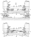
以下、図面に基づいて、本発明の第1の実施の形態について詳細に説明する。図1は、橋梁桁25の両端付近に、昇降装置3a、昇降装置3bを配置した状態を示す立面図である。
Hereinafter, a first embodiment of the present invention will be described in detail with reference to the drawings. FIG. 1 is an elevational view showing a state in which the
第1の実施の形態では、立体交差の道路構造物を構築する際に、橋梁桁25を橋脚等に架設する方法について説明する。図1では、まず、地盤1内に杭19を設置し、杭19の上方にフーチング17を形成する。そして、フーチング17付近に支持コンクリート75を形成し、支持コンクリート75に水平台33を固定する。また、地盤1上に複数の架台21を設置し、架台21上に橋梁桁25を組み立てる。橋梁桁25は、鋼製等であり、複数の部材をボルトや溶接で連結して組み立てられる。
In the first embodiment, a method of installing the
橋梁桁25を組み立てた後、橋梁桁25の両端付近に、それぞれ、昇降装置3a、昇降装置3bを配置する。図1に示すように、昇降装置3a、昇降装置3bは、いずれも、水平台33上に配置される。昇降装置3a、昇降装置3bは、いずれも、レグ5、ワーキングジャッキ7、支持梁9を有する。昇降装置3aのレグ5の下端部27には、支持部23aが設けられる。昇降装置3bのレグ5の下端部27には、支持部23bが設けられる。(図1、6、7の支持部23bを変更しました。)
After assembling the
以下に、昇降装置3aの構造について詳細に説明する。図2は、昇降装置3aを橋軸方向から見た立面図である。図2の(a)図は、図1に示すB−Bによる断面図である。図1、図2の(a)図に示すように、支持梁9は、橋梁桁25を支持するものである。レグ5は、支持梁9の両端部に挿通され、支持梁9を支持する。ワーキングジャッキ7は、支持梁9をレグ5に沿って昇降させるための駆動部である。ワーキングジャッキ7は、例えば、支持梁9の上面51に設置される。支持部23aは、水平台33上に載置されて、レグ5を支持する。なお、レグ5は、橋梁桁25にも挿通される。(橋梁桁25の幅の変更に伴い、追加しました。図1、2、4、6、7〜10と合わせてご確認くださいませ。)
Below, the structure of the raising / lowering
図3は、昇降装置3aの下端部付近を橋軸直角方向から見た立面図である。図3の(a)図は、図2の(a)図に示す矢印Cの方向から見た図である。図1、図2の(a)図、図3の(a)図に示すように、支持部23aは、ピン11、タフローラ13、スライドシリンダ15、可動ストッパ43等からなる。
FIG. 3 is an elevational view of the vicinity of the lower end of the
図2の(a)図、図3の(a)図に示すように、ピン11は、レグ5の下端に固定された連結治具29と、タフローラ13の上端に固定された連結治具31とを連結する部材である。タフローラ13は、水平台33に固定された溝型治具35の内部に配置される。溝型治具35は、底面35cと、底面35cの橋軸方向の2辺に設けられた側面35aと、橋軸直角方向の1辺に設けられた側面35bとからなる。溝型治具35は、水平台33上に、橋軸方向の溝を形成する。溝型治具35の側面35aと連結治具31との間には、サイドローラ37が設けられる。
As shown in FIG. 2A and FIG. 3A, the
スライドシリンダ15は、橋軸方向に伸縮するように配置される。スライドシリンダ15の一端は、固定具47を介して、連結治具31の橋軸方向の端部のうち、溝型治具35の側面35bと対向しない端部に連結される。スライドシリンダ15の他端は、固定具41を介して、溝型治具35に固定された固定治具39に連結される。可動ストッパ43は、位置決め棒45を介して、溝型治具35の側面35bに連結される。可動ストッパ43は、位置決め棒45の任意の位置に固定することができる。
The
図3の(a)図に示すように、ピン11は、矢印E方向にレグ5を回転させる。タフローラ13は、橋軸方向すなわち矢印Fに示す方向に連結部23aを水平移動させる。サイドローラ37(図2の(a)図)は、タフローラ13による連結部23aの移動を補助する。スライドシリンダ15は、伸縮して連結部23aの移動を制御する。可動ストッパ43は、連結部23aの停止を補助する。
As shown in FIG. 3A, the
図4は、昇降装置3aを上方向から見た図である。図4は、図2の(a)図に示す矢印Dの方向から見た図である。図5は、支持梁9と橋梁桁25との連結部87付近の断面図である。図5の(a)図は、図4に示すG−Gによる断面図である。
FIG. 4 is a view of the
図2の(a)図、図4に示すように、連結部87は、橋梁桁25の両側部に1ヶ所ずつ設けるのが望ましい。図2の(a)図、図4、図5の(a)図に示すように、各連結部87は、ピン69、4本の連結鋼材53等からなる。ピン69は、支持梁9の下面61に固定された連結治具63と、橋梁桁25の上面55に固定された連結治具65とを連結する部材である。
As shown in FIG. 2A and FIG. 4, it is desirable to provide one connecting
連結鋼材53は、上下方向に配置されたゲビンデスタープ、PC鋼棒等である。支持梁9の両側面89には、凸部60が設けられ(図4)、凸部60の上面には固定板49が固定される(図2の(a)図、図4、図5の(a)図)。固定板49の橋軸直角方向の幅は凸部60の幅より大きく、連結鋼材53は、上端部が固定板49に挿通された状態で、凸部60の両側に配置される(図2の(a)図)。連結鋼材53の上端部は、ナット73を用いて固定板49に固定される(図2の(a)図、図4、図5の(a)図)。
The connecting
橋梁桁25の上面55には、凸部67が設けられ、凸部67の上面には固定板57が固定される(図2の(a)図、図5の(a)図)。固定板57の橋軸直角方向の幅は凸部67の幅より大きく、連結鋼材53の下端部は、固定板57に挿通された状態で、凸部67の両側に配置される(図2の(a)図)。
A
図5の(a)図に示す状態のとき、連結治具65が固定された橋梁桁25は、ピン69により、矢印Hに示す方向に回転可能である。
In the state shown in FIG. 5A, the
図1に示す昇降装置3bは、昇降装置3aとほぼ同様の構造を有するが、支持部23bのみが昇降装置3aとは異なる。昇降装置3bの支持部23bは、レグ5をピン支持するような構造である。すなわち、支持部23bは、図1に示すように、レグ27の下端部27に固定された連結治具29と、水平台33上に固定された連結治具83と、連結治具29と連結治具83とを回転可能に一体化するピン11からなる。
The
図1に示すように配置された昇降装置3a、昇降装置3bは、上げ越し状態とした橋梁桁25と支持梁9とを、図2の(a)図、図5の(a)図に示すように、連結部87のピン69を用いて結合する。すなわち、橋梁桁25の両端部付近は、支持梁9に対して、図5の(a)図に示す矢印Hの方向に回転可能に連結される。なお、橋梁桁25の上げ越し量は、橋梁桁25の自重により生じると考えられるたわみ量を算出して決定する。
The
支持梁9と橋梁桁25とをピン69で結合した後、ワーキングジャッキ7を用いて支持梁9をレグ5に沿って上昇させ、橋梁桁25を図1に示す矢印Aの方向に上昇させる。このとき、昇降装置3aのレグ5の支持部23aの水平方向の移動は、図3の(a)図に示すように、スライドシリンダ15、可動ストッパ43等によって固定される。
After the
図6は、図1に続く各工程を示す立面図である。図6の(a)図は、橋梁桁25が架台21から離れた状態を示す立面図である。図1に示す状態から、橋梁桁25を上昇させると、図6の(a)図に示すように、橋梁桁25が架台21から離れる。このとき、橋梁桁25の両端部付近が図5の(a)図に示す矢印Hの方向に回転し、橋梁桁25にあらかじめ設けた上げ越しによって、橋梁桁25の自重によるたわみが吸収される。
FIG. 6 is an elevation view showing each step subsequent to FIG. FIG. 6A is an elevation view showing a state in which the
図2の(b)図、図5の(b)図は、支持梁9に橋梁桁25を剛結合した状態を示す。図6の(a)図において、橋梁桁25の水平度、レグ5の垂直度を確認した後、図2の(b)図、図5の(b)図に示すように、支持梁9と固定板57との間にレベル調整スペーサ59を設置する。さらに、ナット71を用いて、連結鋼材53の下端部を固定板57に固定する。これにより、ピン69の回転が固定され、橋梁桁25の両端部付近は、支持梁9に剛結合される。
2B and FIG. 5B show a state in which the
図6の(b)図は、橋梁桁25をさらに上昇させた状態を示す立面図である。支持梁9に橋梁桁25を剛結合した後、ワーキングジャッキ7を用いて支持梁9をレグ5に沿って上昇させ、橋梁桁25を図6の(a)図に示す矢印Iの方向にさらに上昇させて、図6の(b)図に示す状態とする。
FIG. 6B is an elevation view showing a state where the
図6の(c)図は、橋梁桁25を橋脚77および橋台79に架設した状態を示す立面図である。図6の(b)に示す状態とした後、昇降装置3b側のフーチング17上に、第1の支持構造である橋脚77を構築する。そして、ワーキングジャッキ7を用いて支持梁9をレグ5に沿って下降させ、橋梁桁25の昇降装置3b側の端部付近を、図6の(c)図に示すように、橋脚77に支持させる。さらに、昇降装置3bを撤去する。
FIG. 6C is an elevational view showing a state in which the
橋脚77の構築と並行して、昇降装置3a側のフーチング17上に、第2の支持構造である橋台79を構築する。そして、橋脚77を支点として図6の(c)図に示す矢印Jの方向に橋梁桁25を回転させ、昇降装置3a側の端部付近を、橋台79に支持させる。
In parallel with the construction of the pier 77, an
橋梁桁25を矢印Jに示す方向に回転させるには、まず、図3の(a)図に示す可動ストッパ43を、図3の(b)図に示すように移動させ、位置決め棒45に再度固定する。これにより、支持部23aの水平移動が可能となる。可動ストッパ43の再固定位置は、橋梁桁25の回転による支持部23aの水平移動量を事前に把握して決定する。
In order to rotate the
そして、図6の(c)図に示すように、ワーキングジャッキ7を用いて支持梁9をレグ5に沿って下降させ、橋梁桁25を矢印J1の方向に下降させる作業と、スライドジャッキ15で移動量を制御しつつ、タフローラ13とサイドローラ37(図2の(a)図)を用いて支持部23aを矢印J2の方向に水平移動させる作業とを繰り返して、橋梁桁25を矢印Jの方向に回転させる。橋梁桁25の端部を橋台79に据え付けた後、昇降装置3aを撤去する。
Then, as shown in FIG. 6C, the working
このように、第1の実施の形態では、橋梁桁25を保持する昇降装置3a、昇降装置3bにおいて、支持梁9と橋梁桁25とを結合する際に、ピン69による結合または剛結合を、適宜選択できるようにする。これにより、上げ越し状態の橋梁桁25をピン69により支持梁9に回転可能に結合し、橋梁桁25を上昇させた後、橋梁桁25およびレグ5のたわみがない状態で橋梁桁25と支持梁9とを剛結合することができる。
Thus, in the first embodiment, when the
また、昇降装置3aに、支持部23aの水平移動を可能にするタフローラ13等を設ける。これにより、図6の(c)図に示すように、昇降装置3aを用いて、橋梁桁25の下降と支持部23aの水平移動を繰り返して、橋梁桁25を橋台79に確実かつ容易に架設することができる。
Further, the elevating
なお、第1の実施の形態は、図6の(c)図に示す橋梁と橋脚の間の他、2ヶ所の橋脚の間に桁を架設する場合にも適用できる。第1の実施の形態では、橋梁桁25の片端付近を橋脚77に支持させる作業の後、他端を橋台79に支持させる作業を行ったが、この2つの作業の間に、橋梁桁25上で他の橋梁桁を組み立てて押出し架設する作業を行うこともできる。
The first embodiment can also be applied to a case where a girder is installed between two bridge piers, in addition to between the bridge and the pier shown in FIG. 6 (c). In the first embodiment, after the work for supporting the vicinity of one end of the
また、昇降装置3a、昇降装置3bの連結部87の構造は、図2、図4、図5に示すものに限らない。連結部は、支持梁と橋梁桁とを結合する際に、ピン結合または剛結合を適宜選択できるような構造であればよい。
Moreover, the structure of the
さらに、支持部23aの構造は、図3に示すものに限らない。支持部23aは、レグ5の下端部27を、回転かつ水平移動可能に支持するような構造であればよい。支持部23bは、レグ5の下端部27を回転可能に支持するような構造であればよい。
Furthermore, the structure of the
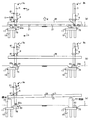
次に、第2の実施の形態について説明する。第2の実施の形態では、立体交差の道路構造物を構築する際に、第1の実施の形態の昇降装置3aのかわりに他の昇降装置3cを用いて橋梁桁を橋脚等に架設する方法について説明する。図7は、橋梁桁25を橋脚および橋台に架設するための各工程を示す立面図である。図7の(a)図は、橋梁桁25の両端付近に、昇降装置3c、昇降装置3bを配置した状態を示す立面図である。図7の(a)図は、第1の実施の形態の図1に相当する。
Next, a second embodiment will be described. In the second embodiment, when a three-dimensional intersection road structure is constructed, a bridge girder is installed on a pier or the like using another
図7の(a)図では、まず、第1の実施の形態と同様に、杭19、フーチング17、支持コンクリート75を形成し、支持コンクリート75上に水平台33を固定する。また、架台21上に橋梁桁25を組み立てる。そして、橋梁桁25の両端付近に、それぞれ、昇降装置3c、昇降装置3bを配置する。
In FIG. 7A, first, as in the first embodiment, the
図7の(a)図に示すように、昇降装置3c、昇降装置3bは、いずれも、水平台33上に配置される。昇降装置3bは、第1の実施の形態で用いたものと同じ構成である。昇降装置3cは、昇降装置3aおよび昇降装置3bと同様のレグ5、ワーキングジャッキ7、支持梁9を有し、レグ5の下端部27には支持部23cが設けられる。また、支持梁9と橋梁桁25の間にローラ受81が配置される。ワーキングジャッキ7の上面にもローラ受81が配置される。
As shown in FIG. 7A, the
以下に、昇降装置3cの支持部23c、ローラ受81について詳細に説明する。図8は、昇降装置3cを橋軸方向から見た立面図である。図8は、図7の(a)図に示すP−Pによる断面図である。図9は、昇降装置3cの下半部付近を橋軸直角方向から見た立面図である。図9は、昇降装置3cを図8に示す矢印Mの方向から見た図である。
Below, the
支持部23cは、支持部23bと同様の構造である。すなわち、図8、図9に示すように、支持部23cは、レグ5の下端部27に固定された連結部材29と、水平台33の上面に固定された連結治具83とを、ピン11で結合したものである。ピン11は、図9に示す矢印Oの方向にレグ5を回転させる。
The
図10は、昇降装置3cの水平断面図である。図10は、図8に示すN−Nによる断面図である。図11は、支持梁9と橋梁桁25との連結部87付近の断面図である。図11は、図10に示すQ−Qによる断面図である。
FIG. 10 is a horizontal sectional view of the
ローラ受81は、支持梁9と橋梁桁25の間、ワーキングジャッキ7の上面に配置される(図8、図9)。ローラ受81は、コの字型の部材であり、内空にレグ5が配置される(図10)。ローラ受81は、橋梁桁25の上面55、ワーキングジャッキ7の上面に固定される(図8、図10)。ローラ受81の内側面にはローラ85が設けられる(図9、図10)。ローラ85は回転し、レグ5に沿って移動する。なお、昇降装置3cの連結部87は、昇降装置3aの連結部87と同様の構造である(図8、図11)。
The
図7の(a)図に示す昇降装置3c、昇降装置3bは、上げ越し状態とした橋梁桁25と支持梁9とを、連結部87のピン69を用いて結合する。連結部87の連結鋼材53は、図8、図11に示すように、上端部のみが固定板49に固定される。すなわち、橋梁桁25の両端部付近は、支持梁9に対して、図11に示す矢印Rの方向に回転可能に連結される。なお、橋梁桁25の上げ越し量は、橋梁桁25の自重により生じると考えられるたわみ量を算出して決定する。
7A and 7B, the elevating
支持梁9と橋梁桁25とをピン69で結合した後、ワーキングジャッキ7を用いて支持梁9をレグ5に沿って上昇させ、橋梁桁25を図7の(a)に示す矢印Kの方向に上昇させる。橋梁桁25を上昇させると、橋梁桁25が架台21から離れる。このとき、橋梁桁25が図11に示す矢印Rの方向に回転し、橋梁桁25にあらかじめ設けた上げ越しによって、橋梁桁25の自重によるたわみが吸収される。
After the
橋梁桁25を架台21から離し、橋梁桁25の水平度、レグ5の垂直度を確認した後、第1の実施の形態における図2の(b)図、図5の(b)図と同様にして、支持梁9と固定板57との間にレベル調整スペーサ59を設置する。さらに、ナット71を用いて、連結鋼材53の下端部を固定板57に固定する。これにより、ピン69の回転が固定され、橋梁桁25の両端部付近が支持梁9に剛結合される。
After the
図7の(b)図は、橋梁桁25をさらに上昇させた状態を示す立面図である。支持梁9に橋梁桁25を剛結合した後、ワーキングジャッキ7を用いて支持梁9をレグ5に沿って上昇させ、橋梁桁25をさらに上昇させて、図7の(b)図に示す状態とする。
FIG. 7B is an elevational view showing a state where the
図7の(c)図は、橋梁桁25を橋脚77および橋台79に架設した状態を示す立面図である。図7の(b)に示す状態とした後、昇降装置3b側のフーチング17上に、第1の支持構造である橋脚77を構築する。そして、ワーキングジャッキ7を用いて支持梁9をレグ5に沿って下降させ、橋梁桁25の昇降装置3b側の端部付近を、図7の(c)図に示すように、橋脚77に支持させる。さらに、昇降装置3bを撤去する。
FIG. 7C is an elevation view showing a state in which the
橋脚77の構築と並行して、昇降装置3a側のフーチング17上に、第2の支持構造である橋台79を構築する。そして、橋脚77を支点として図7の(c)図に示す矢印Lの方向に橋梁桁25を回転させ、昇降装置3c側の端部を、橋台79に支持させる。
In parallel with the construction of the pier 77, an
橋梁桁25を矢印Lに示す方向に回転させるには、まず、昇降装置3cの連結部87のナット71およびレベル調整用スペーサ59(図2の(b)図、図5の(b)図)を撤去し、支持梁9と橋梁桁25との剛結合を、図8、図11に示すようなピン69による結合に戻す。
In order to rotate the
次に、橋梁桁25を連結部87のピン69によって支持梁9に対して回転させつつ、レグ5を支持部23cのピン11によって水平台33に対して回転させて、橋梁桁25を矢印Lの方向に回転させる。そして、橋梁桁25の端部を橋台79に据え付けた後、昇降装置3cを撤去する。
Next, while the
このように、第2の実施の形態では、橋梁桁25を保持する昇降装置3c、昇降装置3bにおいて、支持梁9と橋梁桁25とを結合する際に、ピン69による結合または剛結合を、適宜選択できるようにする。これにより、上げ越し状態の橋梁桁25をピン69により支持梁9に回転可能に結合し、橋梁桁25を上昇させた後、橋梁桁25およびレグ5のたわみがない状態で橋梁桁25と支持梁9とを剛結合することができる。
As described above, in the second embodiment, when the
また、橋梁桁25を橋台79に架設する前に、昇降装置3cにおける支持梁9と橋梁桁25との剛結合を、図8、図11に示すようなピン69による結合に戻す。これにより、支持部23cのピン11および連結部87のピン69を回転させて、橋梁桁25を橋台79に確実かつ容易に架設することができる。
Further, before the
なお、第2の実施の形態は、図7の(c)図に示す橋梁と橋脚の間の他、2ヶ所の橋脚の間に桁を架設する場合にも適用できる。第2の実施の形態では、橋梁桁25の片端付近を橋脚77に支持させる作業の後、他端を橋台79に支持させる作業を行ったが、この2つの作業の間に、橋梁桁25上で他の橋梁桁を組み立てて押出し架設する作業を行うこともできる。
Note that the second embodiment can be applied to a case where a girder is installed between two bridge piers in addition to between the bridge and the pier shown in FIG. 7C. In the second embodiment, after the work of supporting the vicinity of one end of the
また、昇降装置3c、昇降装置3bの連結部87の構造は、図8、図10、図11に示すものに限らない。連結部は、支持梁と橋梁桁とを結合する際に、ピン結合または剛結合を適宜選択できるような構造であればよい。さらに、支持部23c、支持部23bの構造は、レグ5の下端部27を回転可能に支持するような構造であればよい。
Moreover, the structure of the
以上、添付図面を参照しながら本発明にかかる構造物の構築方法、構造物および昇降装置の好適な実施形態について説明したが、本発明はかかる例に限定されない。当業者であれば、特許請求の範囲に記載された技術的思想の範疇内において各種の変更例または修正例に想到し得ることは明らかであり、それらについても当然に本発明の技術的範囲に属するものと了解される。 The preferred embodiments of the structure construction method, the structure, and the lifting device according to the present invention have been described above with reference to the accompanying drawings, but the present invention is not limited to such examples. It is obvious for those skilled in the art that various modifications or modifications can be conceived within the scope of the technical idea described in the claims, and these are naturally within the technical scope of the present invention. It is understood that it belongs.
本発明の構造物の構築方法、構造物および昇降装置は、例えば、柱等の支持構造物に、桁に相当する大スパンの屋根構造を架設して構造物を構築する場合にも用いることができる。 The structure construction method, the structure, and the lifting device of the present invention can be used, for example, when constructing a structure by laying a roof structure having a large span corresponding to a girder on a support structure such as a pillar. it can.
1………地盤
3a、3b、3c………昇降装置
5………レグ
7………ワーキングジャッキ
9………支持梁
11、69………ピン
13………タフローラ
15………スライドシリンダ
21………架台
23a、23b、23c………支持部
25………橋梁桁
29、31、63、65、83………連結治具
35………溝型治具
37………サイドローラ
43………可動ストッパ
45………位置決め棒
49、57………固定板
53………連結鋼材
59………レベル調整用スペーサ
60、67………凸部
71、73………ナット
77………橋脚
79………橋台
81………ローラ受
85………ローラ
87………連結部
1 .........
Claims (8)
上げ越し状態とした前記桁の端部付近を、前記支持梁に第2のピンを用いて結合する工程(b)と、
前記支持梁を前記レグに沿って上昇させ、前記桁の上げ越しがなくなった時点で、前記第2のピンの回転を固定する工程(c)と、
前記支持梁を前記レグに沿って昇降させ、前記桁の片端を第1の支持構造に支持させる工程(d)と、
前記第1の支持構造を支点として前記桁を回転させ、前記桁の他端を第2の支持構造に支持させる工程(e)と、
を具備することを特徴とする構造物の構築方法。 An elevating device having a support beam, a leg that supports the support beam, and a drive unit that raises and lowers the support beam along the leg, while supporting a lower end portion of the leg by a first pin, A step (a) of arranging near both ends;
A step (b) of connecting the vicinity of the end portion of the spar in an over-raised state to the support beam using a second pin;
(C) fixing the rotation of the second pin when the support beam is raised along the leg and the girders are no longer raised;
Elevating and lowering the support beam along the leg and supporting one end of the beam on the first support structure;
Rotating the beam with the first support structure as a fulcrum, and supporting the other end of the beam on the second support structure;
A structure construction method characterized by comprising:
前記支持梁を支持するレグと、
前記支持梁を前記レグに沿って昇降させる駆動部と、
前記レグの下端部を支持する第1のピンと、
前記支持梁と桁とを結合する第2のピンと、
前記第2のピンの回転を固定するための固定具と、
を具備することを特徴とする昇降装置。 A support beam;
A leg for supporting the support beam;
A drive unit for raising and lowering the support beam along the leg;
A first pin that supports the lower end of the leg;
A second pin connecting the support beam and the beam;
A fixture for fixing rotation of the second pin;
Elevating device characterized by comprising.
Priority Applications (1)
| Application Number | Priority Date | Filing Date | Title |
|---|---|---|---|
| JP2004294708A JP4217203B2 (en) | 2004-10-07 | 2004-10-07 | Structure construction method and lifting device |
Applications Claiming Priority (1)
| Application Number | Priority Date | Filing Date | Title |
|---|---|---|---|
| JP2004294708A JP4217203B2 (en) | 2004-10-07 | 2004-10-07 | Structure construction method and lifting device |
Publications (2)
| Publication Number | Publication Date |
|---|---|
| JP2006104832A true JP2006104832A (en) | 2006-04-20 |
| JP4217203B2 JP4217203B2 (en) | 2009-01-28 |
Family
ID=36374882
Family Applications (1)
| Application Number | Title | Priority Date | Filing Date |
|---|---|---|---|
| JP2004294708A Expired - Fee Related JP4217203B2 (en) | 2004-10-07 | 2004-10-07 | Structure construction method and lifting device |
Country Status (1)
| Country | Link |
|---|---|
| JP (1) | JP4217203B2 (en) |
Cited By (2)
| Publication number | Priority date | Publication date | Assignee | Title |
|---|---|---|---|---|
| CN106835986A (en) * | 2017-01-13 | 2017-06-13 | 成都启立辰智科技有限公司 | Bridge pier internal model structure |
| CN110528395A (en) * | 2019-09-23 | 2019-12-03 | 中交第二航务工程局有限公司 | A kind of grouping folding mobile formwork and its curve are crossed across construction method |
Families Citing this family (5)
| Publication number | Priority date | Publication date | Assignee | Title |
|---|---|---|---|---|
| FR2859485B1 (en) | 2003-09-04 | 2006-09-15 | Essilor Int | METHOD FOR PRODUCING AN ANTI-REFLECTIVE TREATMENT ON AN OPTICAL SUBSTRATE, OPTICAL SUBSTRATE OBTAINED BY THIS METHOD AND DEVICE FOR IMPLEMENTING THE METHOD |
| CN100582888C (en) * | 2004-06-11 | 2010-01-20 | 鸿富锦精密工业(深圳)有限公司 | Light conducting plate |
| KR101147620B1 (en) | 2009-12-30 | 2012-05-23 | 세방 주식회사 | Installing method for upper plate of bridge using climbing jack system |
| CN106498838B (en) * | 2016-12-28 | 2018-03-16 | 西安科技大学 | A kind of arch bridge and suspension bridge combined type self-balancing bridge and its construction method |
| CN106758855B (en) * | 2017-03-07 | 2018-10-30 | 中铁大桥局集团有限公司 | Arc-shaped pier cap construction arch support component and arc-shaped pier cap construction method |
-
2004
- 2004-10-07 JP JP2004294708A patent/JP4217203B2/en not_active Expired - Fee Related
Cited By (2)
| Publication number | Priority date | Publication date | Assignee | Title |
|---|---|---|---|---|
| CN106835986A (en) * | 2017-01-13 | 2017-06-13 | 成都启立辰智科技有限公司 | Bridge pier internal model structure |
| CN110528395A (en) * | 2019-09-23 | 2019-12-03 | 中交第二航务工程局有限公司 | A kind of grouping folding mobile formwork and its curve are crossed across construction method |
Also Published As
| Publication number | Publication date |
|---|---|
| JP4217203B2 (en) | 2009-01-28 |
Similar Documents
| Publication | Publication Date | Title |
|---|---|---|
| JP5179804B2 (en) | Mobile suspension support | |
| JP4563413B2 (en) | Bridge girder construction method | |
| JP5059491B2 (en) | Assembly method of mobile suspension support | |
| KR101582611B1 (en) | Slab gap adjustment apparatus with longitudinal moving and bridge construction method therewith | |
| JP4777922B2 (en) | Mobile suspension support | |
| KR100961547B1 (en) | Hydraulic lifting device, the bracket and the method for changing bridge bearings using them | |
| JP4217203B2 (en) | Structure construction method and lifting device | |
| KR20190041189A (en) | Modular work platform of a long span bridge main tower rebar and construction method using the same | |
| JP6712501B2 (en) | High-rise building demolition system and demolition method | |
| KR20090100476A (en) | A bridge lifting apparatus and bridge lifting method using the same | |
| KR102089758B1 (en) | Formwork structure supported by column unit | |
| JP6508958B2 (en) | Demolition system and demolition method | |
| JP6508959B2 (en) | Demolition system and demolition method | |
| KR20090101878A (en) | Struts constructing apparatus and method for bridge | |
| KR200363059Y1 (en) | Upper bridge structure construcion system with precast segment deck or box using a lifting traveller | |
| JP6059176B2 (en) | Mobile lifting scaffold for assembling temporary elevated jetty | |
| CN110080271B (en) | Construction method for embedded quality control of foundation bolt embedded part | |
| KR100769556B1 (en) | Method of bent construction for temporary bridge | |
| KR20060002650A (en) | Upper bridge structure construcion method with precast segment deck or box using a lifting traveller | |
| JP2018123559A (en) | Inclination repair method of uneven settlement building | |
| JP4519588B2 (en) | Three-dimensional intersection construction method | |
| KR102451807B1 (en) | Cantilever frame unit for concrete pouring and expansion and repair method using of the same | |
| KR200290739Y1 (en) | Jacking system of bridge repair | |
| CN112982136B (en) | Rapid installation structure of small box girder and cover girder of viaduct and construction method thereof | |
| JP7245472B2 (en) | Anti-scattering system and demolition method for existing buildings |
Legal Events
| Date | Code | Title | Description |
|---|---|---|---|
| A711 | Notification of change in applicant |
Free format text: JAPANESE INTERMEDIATE CODE: A712 Effective date: 20060804 |
|
| A621 | Written request for application examination |
Free format text: JAPANESE INTERMEDIATE CODE: A621 Effective date: 20061120 |
|
| A521 | Written amendment |
Free format text: JAPANESE INTERMEDIATE CODE: A523 Effective date: 20061215 |
|
| RD02 | Notification of acceptance of power of attorney |
Free format text: JAPANESE INTERMEDIATE CODE: A7422 Effective date: 20061215 |
|
| A521 | Written amendment |
Free format text: JAPANESE INTERMEDIATE CODE: A821 Effective date: 20061215 |
|
| A711 | Notification of change in applicant |
Free format text: JAPANESE INTERMEDIATE CODE: A712 Effective date: 20070717 |
|
| A977 | Report on retrieval |
Free format text: JAPANESE INTERMEDIATE CODE: A971007 Effective date: 20080724 |
|
| A131 | Notification of reasons for refusal |
Free format text: JAPANESE INTERMEDIATE CODE: A131 Effective date: 20080729 |
|
| A521 | Written amendment |
Free format text: JAPANESE INTERMEDIATE CODE: A523 Effective date: 20080905 |
|
| RD02 | Notification of acceptance of power of attorney |
Free format text: JAPANESE INTERMEDIATE CODE: A7422 Effective date: 20080905 |
|
| A521 | Written amendment |
Free format text: JAPANESE INTERMEDIATE CODE: A821 Effective date: 20080905 |
|
| TRDD | Decision of grant or rejection written | ||
| A01 | Written decision to grant a patent or to grant a registration (utility model) |
Free format text: JAPANESE INTERMEDIATE CODE: A01 Effective date: 20081104 |
|
| A01 | Written decision to grant a patent or to grant a registration (utility model) |
Free format text: JAPANESE INTERMEDIATE CODE: A01 |
|
| A61 | First payment of annual fees (during grant procedure) |
Free format text: JAPANESE INTERMEDIATE CODE: A61 Effective date: 20081107 |
|
| R150 | Certificate of patent or registration of utility model |
Free format text: JAPANESE INTERMEDIATE CODE: R150 |
|
| FPAY | Renewal fee payment (event date is renewal date of database) |
Free format text: PAYMENT UNTIL: 20111114 Year of fee payment: 3 |
|
| S531 | Written request for registration of change of domicile |
Free format text: JAPANESE INTERMEDIATE CODE: R313531 |
|
| FPAY | Renewal fee payment (event date is renewal date of database) |
Free format text: PAYMENT UNTIL: 20111114 Year of fee payment: 3 |
|
| R350 | Written notification of registration of transfer |
Free format text: JAPANESE INTERMEDIATE CODE: R350 |
|
| FPAY | Renewal fee payment (event date is renewal date of database) |
Free format text: PAYMENT UNTIL: 20111114 Year of fee payment: 3 |
|
| S111 | Request for change of ownership or part of ownership |
Free format text: JAPANESE INTERMEDIATE CODE: R313117 |
|
| FPAY | Renewal fee payment (event date is renewal date of database) |
Free format text: PAYMENT UNTIL: 20111114 Year of fee payment: 3 |
|
| R360 | Written notification for declining of transfer of rights |
Free format text: JAPANESE INTERMEDIATE CODE: R360 |
|
| FPAY | Renewal fee payment (event date is renewal date of database) |
Free format text: PAYMENT UNTIL: 20111114 Year of fee payment: 3 |
|
| R370 | Written measure of declining of transfer procedure |
Free format text: JAPANESE INTERMEDIATE CODE: R370 |
|
| FPAY | Renewal fee payment (event date is renewal date of database) |
Free format text: PAYMENT UNTIL: 20111114 Year of fee payment: 3 |
|
| S111 | Request for change of ownership or part of ownership |
Free format text: JAPANESE INTERMEDIATE CODE: R313117 |
|
| S531 | Written request for registration of change of domicile |
Free format text: JAPANESE INTERMEDIATE CODE: R313531 |
|
| S533 | Written request for registration of change of name |
Free format text: JAPANESE INTERMEDIATE CODE: R313533 |
|
| FPAY | Renewal fee payment (event date is renewal date of database) |
Free format text: PAYMENT UNTIL: 20111114 Year of fee payment: 3 |
|
| R350 | Written notification of registration of transfer |
Free format text: JAPANESE INTERMEDIATE CODE: R350 |
|
| FPAY | Renewal fee payment (event date is renewal date of database) |
Free format text: PAYMENT UNTIL: 20141114 Year of fee payment: 6 |
|
| R250 | Receipt of annual fees |
Free format text: JAPANESE INTERMEDIATE CODE: R250 |
|
| S533 | Written request for registration of change of name |
Free format text: JAPANESE INTERMEDIATE CODE: R313533 |
|
| R350 | Written notification of registration of transfer |
Free format text: JAPANESE INTERMEDIATE CODE: R350 |
|
| S111 | Request for change of ownership or part of ownership |
Free format text: JAPANESE INTERMEDIATE CODE: R313117 |
|
| S531 | Written request for registration of change of domicile |
Free format text: JAPANESE INTERMEDIATE CODE: R313531 |
|
| R350 | Written notification of registration of transfer |
Free format text: JAPANESE INTERMEDIATE CODE: R350 |
|
| R250 | Receipt of annual fees |
Free format text: JAPANESE INTERMEDIATE CODE: R250 |
|
| R250 | Receipt of annual fees |
Free format text: JAPANESE INTERMEDIATE CODE: R250 |
|
| LAPS | Cancellation because of no payment of annual fees |