JP2006080296A - Dicing apparatus - Google Patents
Dicing apparatus Download PDFInfo
- Publication number
- JP2006080296A JP2006080296A JP2004262662A JP2004262662A JP2006080296A JP 2006080296 A JP2006080296 A JP 2006080296A JP 2004262662 A JP2004262662 A JP 2004262662A JP 2004262662 A JP2004262662 A JP 2004262662A JP 2006080296 A JP2006080296 A JP 2006080296A
- Authority
- JP
- Japan
- Prior art keywords
- blade
- cutting water
- cutting
- injection
- injection member
- Prior art date
- Legal status (The legal status is an assumption and is not a legal conclusion. Google has not performed a legal analysis and makes no representation as to the accuracy of the status listed.)
- Pending
Links
Images

Abstract
Description
本発明はダイシング装置に関するもので、特にブレードへ切削水を効果的に供給する噴射部材を設けたダイシング装置に関するものである。 The present invention relates to a dicing apparatus, and particularly to a dicing apparatus provided with an injection member that effectively supplies cutting water to a blade.
半導体装置や電子部品が形成されたウェーハ等のワークを個々のチップに分割するダイシング装置には、少なくともスピンドルによって高速に回転されるブレードと、ワークを載置するワークテーブルと、ワークテーブルとブレードとの相対的位置を変化させるX、Y、Z、θの各移動軸とが設けられており、これらの各移動軸の動作によってワークに対して溝入れや切断加工を施す。 A dicing apparatus that divides a work such as a wafer on which a semiconductor device or an electronic component is formed into individual chips includes at least a blade that is rotated at high speed by a spindle, a work table on which the work is placed, a work table and a blade X, Y, Z, and θ moving axes that change the relative positions of the workpieces are provided, and the workpieces are grooved and cut by the operations of these moving axes.
そして加工時には、ワークから研削屑等の汚染物(コンタミ又はコンタミネーションと呼ばれる)が発生すると共に、ブレードとワークとの間で摩擦熱が発生するため、ワーク面上や加工点付近、ブレードなどに対して潤滑、冷却、洗浄を目的として切削水を供給していた。その中でも特にブレードを冷却する際には、ブレード側面に設けられ、回転面に対して真横から垂直に切削水を噴射する噴射部材や、切削点近傍に設けられ、ブレード外周部からブレードの回転中心に向かって切削水を供給する噴射部材を設けることが行われてきた(例えば、特許文献1、2参照。)。
しかし、前述の特許文献1、2に記載されたような噴射部材を使用した場合、切削水をブレード真横やブレードの回転方向に対して逆らうように当てることになるため、ブレードに負荷がかかり、ブレードが振動して加工品質に影響が出る問題があった。
However, when an injection member such as that described in
本発明はこのような問題に対してなされたもので、ダイシング装置において、回転中のブレードへの切削水による負荷を低減した噴射部材が設けられたダイシング装置を提供することを目的とする。 The present invention has been made to solve such a problem, and an object of the present invention is to provide a dicing apparatus provided with an injection member that reduces a load caused by cutting water on a rotating blade.
本発明は前記目的を達成するために、請求項1に記載の発明は、スピンドルにより高速に回転されるブレードと、ワークを載置して前記ブレードと相対的な運動を行うワークテーブルとを有し、前記ブレードによりワークの溝加工や切断を行うダイシング装置において、前記ブレードを挟んでブレードの両側面に設けられ、切削点近傍に切削水を供給する一対の噴射部材を有し、前記噴射部材には夫々複数の切削水噴射口が水平に並んで設けられ、前記複数の切削水噴射口は、切削点におけるブレード回転方向に向けてブレード面へ斜めに切削水を噴射するように開口されていることを特徴としている。 In order to achieve the above object, the present invention includes a blade that is rotated at a high speed by a spindle and a work table on which a work is placed to perform relative movement with the blade. In the dicing apparatus that performs grooving and cutting of a workpiece with the blade, the dicing device includes a pair of injection members that are provided on both side surfaces of the blade with the blade interposed therebetween and that supply cutting water in the vicinity of a cutting point. Each of the plurality of cutting water injection ports is provided horizontally, and the plurality of cutting water injection ports are opened so as to inject cutting water obliquely toward the blade surface in the blade rotation direction at the cutting point. It is characterized by being.
請求項1の発明によれば、切削点におけるブレード回転方向に向けてブレード面へ斜めに切削水を噴射するので、ブレードの回転に逆らうことなく切削水が供給される。このため、回転中のブレードへの切削水による負荷が減り、ブレードの振動を抑えることができるので加工品質を向上させる。また、回転中のブレードへの切削水による負荷が減ることで、スピンドルの回転負荷も減り、スピンドルの消費電力を抑える効果もある。 According to the first aspect of the present invention, since the cutting water is jetted obliquely toward the blade surface in the blade rotation direction at the cutting point, the cutting water is supplied without countering the rotation of the blade. For this reason, the load by the cutting water on the rotating blade is reduced, and the vibration of the blade can be suppressed, so that the processing quality is improved. Further, since the load due to the cutting water on the rotating blade is reduced, the rotational load of the spindle is also reduced, and the power consumption of the spindle can be suppressed.
請求項2に記載の発明は、スピンドルにより高速に回転されるブレードと、ワークを載置して前記ブレードと相対的な運動を行うワークテーブルとを有し、前記ブレードによりワークの溝加工や切断を行うダイシング装置において、前記ブレードを含む面内で切削点の近傍に切削水供給用の噴射部材を有し、前記噴射部材の先端が前記ブレード外周の接線方向にあわせて斜めに形成されていることを特徴としている。
The invention described in
請求項2の発明によれば、先端がブレード外周の接線方向に合わせて斜めに形成された噴射部材を切削点近傍に設けるので、ブレードの回転方向に向けて切削水を噴射することができ、回転中のブレードの切削水による負荷を軽減する。
According to the invention of
請求項3に記載の発明は、請求項1又は請求項2の発明に発明において、前記噴射部材には、切削水の噴射位置を調整する噴射位置調整機構が設けられていることを特徴としている。
The invention according to
請求項3の発明によれば、ブレードに噴射される切削水の位置を調整することが可能となり、ブレードのサイズにあわせて噴射位置を変えることができる。
According to the invention of
以上説明したように本発明のダイシング装置によれば、ブレードの回転に対して逆らわずに切削水が供給されるため、回転中のブレードへの切削水による負荷が減り、ブレードの振動を抑えることができるので加工品質を向上させることが可能となる。 As described above, according to the dicing apparatus of the present invention, the cutting water is supplied without countering the rotation of the blade, so that the load of the cutting water on the rotating blade is reduced and the vibration of the blade is suppressed. Therefore, machining quality can be improved.
以下添付図面に従って本発明に係るダイシング装置について好ましい実施の形態について詳説する。尚、各図において同一部材には同一の番号または記号を付している。 Preferred embodiments of a dicing apparatus according to the present invention will be described below in detail with reference to the accompanying drawings. In each figure, the same number or symbol is attached to the same member.
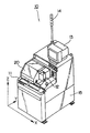
最初に、ダイシング装置の構成について説明する。図1は、本発明に係るダイシング装置の外観を表す斜視図である。ダイシング装置10は、図1に示すように、加工部20、操作・表示部11、撮像手段12、モニターテレビ13、表示灯14、コントローラ15等から構成されている。
First, the configuration of the dicing apparatus will be described. FIG. 1 is a perspective view showing an appearance of a dicing apparatus according to the present invention. As shown in FIG. 1, the
加工部20では、高周波モータ内臓のエアーベアリングで支持されたスピンドルの先端に回転刃であるブレードが取付けられ、30,000rpm〜60,000rpmの高速で回転されると共に、図のZ方向の切り込み送りとY方向のインデックス送りとがなされる。また、加工されるワークを載置するワークテーブルが、θ回転されると共にX方向に研削送りされる。
In the
ワークを加工するブレードは、ダイヤモンド砥粒やCBN砥粒をニッケルで電着した電着ブレードや、金属粉末を混入した樹脂で結合したメタルレジンボンドのブレード等が用いられる。また、ブレードの寸法は、加工内容によって種々選択されるが、通常の半導体ウエーハをダイシングする時は直径50mm、厚さ30μm前後のものが用いられる。 As the blade for processing the workpiece, an electrodeposition blade in which diamond abrasive grains or CBN abrasive grains are electrodeposited with nickel, a metal resin bond blade bonded with a resin mixed with metal powder, or the like is used. Also, the dimensions of the blade are variously selected depending on the processing content, but when dicing an ordinary semiconductor wafer, a blade having a diameter of about 50 mm and a thickness of about 30 μm is used.
ワークの表面を撮像したり、ワークテーブル上面の傷を撮像したりする撮像手段12は、顕微鏡とCCDカメラとからなり、撮像された画像はモニターテレビ13に写し出される。操作・表示部11には、ダイシング装置10の各操作を行うスイッチや表示装置が組込まれている。
The image pickup means 12 for picking up an image of the surface of the work or picking up a flaw on the upper surface of the work table includes a microscope and a CCD camera, and the picked-up image is displayed on the
表示灯14は、ダイシング装置10の動作中、動作終了、異常警報を表示するもので、離れた位置からでも認識できるように高い位置に設けられている。また、ダイシング装置10の各部の動作を制御するコントローラ15は、CPU、メモリ、入出力回路部、各種制御回路部、等からなり、ダイシング装置10の架台内部に組込まれている。
The
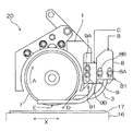
図2は、本発明に係るダイシング装置10の加工部20を示す正面図、図3は図2におけるスピンドル先端のブレード取付け部分の下視図である。ダイシング装置10には、先端にブレード(回転ブレード)7を取付けたスピンドル2が設けられている。ブレード7はフランジ6に挟み込まれ、フランジ6と共にスピンドル2へ固定され、図2における矢印A方向に向かって回転する。
FIG. 2 is a front view showing the
フランジ6とブレード7との周りにはホイールカバー1が取付けられており、ブレード7により巻き上げられる切削水が周りに激しく飛び散るのを防止している。また、ホイールカバー1にはブロック8とブロック9とが取付けられ、ブロック8には噴射部材3が取付けられ、主に洗浄用を目的とした切削水Bが供給され、ブロック9には噴射部材4と噴射部材5とで構成される一対の噴射部材が取付けられており、主にブレードの冷却を目的とした切削水Cが供給されている。この噴射部材によりブレード7に向けて切削水を供給する。
A
噴射部材4と噴射部材5にはそれぞれ図2に示すブレード7の切削点Eにおける回転方向Aに向かうように斜め方向へ、切削水噴射口4A、4A・・・、切削水噴射口5A、5A・・・が複数設けられている。通常噴射口の数は3または4個程度で、更に多数設けられている場合もある。本実施形態の場合3個となっている。
In the
噴射部材3は先端がブレード7の接線方向D(図2における矢印D方向)に合わせて斜めに形成されており、ブレード7を含む面内で、ブレード7の外周部に対してなるべく接近するように、且つ切削点Eの近傍に設けられている。
The
また、噴射部材3が取付けられているブロック8にはノズル位置調整機構81として、位置調整用固定ネジ8Aと長穴8Bが設けられている。同様に噴射部材4、及び噴射部材5が取付けられているブロック9にはノズル位置調整機構91として、位置調整用固定ネジ9Aと長穴9Bが設けられている。これにより、噴射部材3、噴射部材4及び噴射部材5は上下方向に位置調整が可能となり、ブレード7やフランジ6やワーク17等のサイズに合わせて位置調整することができる。
The
この構成により、ブレード7の回転に逆らうことなく切削水が供給されるため、回転中のブレード7への切削水による負荷が減り、ブレード7の振動を抑えることができるので加工品質を向上させる。また、回転中のブレード7への切削水による負荷が減ることで、スピンドルの回転負荷も減り、スピンドルの消費電力を抑える効果もある。 With this configuration, the cutting water is supplied without countering the rotation of the blade 7, so the load of the cutting water on the rotating blade 7 is reduced and the vibration of the blade 7 can be suppressed, so that the machining quality is improved. Further, since the load due to the cutting water on the rotating blade 7 is reduced, the rotational load of the spindle is also reduced, and the power consumption of the spindle can be suppressed.
次に、発明に係るダイシング装置10の作用について説明する。まず、ワークテーブル16にワーク17を吸着載置する。吸着載置後は図1の撮像手段12を使用してワーク17上の基準となる印やワーク17の周縁部等を観察し、加工位置の調整を行う。加工位置調整が完了した後、加工動作を開始する。
Next, the operation of the
加工動作が開始されると、ブレード7はスピンドル2によって高速に回転される。さらに、噴射部材3、噴射部材4及び噴射部材5へ切削水B及び切削水Cの供給が開始され、各噴射部材からブレード7に向けて切削水を噴射する。
When the machining operation is started, the blade 7 is rotated at a high speed by the
このとき、噴射部材4、及び噴射部材5の切削水噴射口4A、4A・・、5A、5A・・はブレード7の回転方向に向かって切削水を噴射するので、前記加工動作中に噴射される切削水はブレード7に与える負荷が小さい。
At this time, the cutting
また、噴射部材3はブレード7の接線方向に向かって先端が加工されているので、回転方向に沿って切削水を噴射することができるため、同じようにブレード7に与える切削水の負荷を小さくできる。
Moreover, since the tip of the
よって、ブレード7の振動発生を抑えることが可能となり、加工品質を向上させ、スピンドル2の回転負荷も減り消費電力の低減の効果も得られる。
Therefore, it is possible to suppress the vibration of the blade 7, improve the processing quality, reduce the rotational load of the
そして、ブレード7が高速に回転し、各噴射部材から切削水が供給され始めると、スピンドル2は最初に加工を行う位置までY方向にインデックス送りされると共に、Z方向へ切り込み送りされる。それに合わせてワークテーブル16はX方向へ加工送りされ、ワークテーブル16上のワーク17に1ライン加工される。
Then, when the blade 7 rotates at high speed and cutting water starts to be supplied from each of the injection members, the
1ラインの加工が終わるとスピンドル2はY方向にインデックス送りされ2ライン目を加工する。これを繰り返し、その方向にあるすべてのラインの加工が終了するとワークテーブル16はθ方向に回転し、次の方向へ向きを変える。通常ワークは賽の目状に加工される為、回転角度は90度が一般的である。すべての方向にあるラインの加工が終了すると加工終了となり、洗浄、乾燥等を行って加工動作は終了する。
When the processing of one line is completed, the
なお、前述した実施の形態において、噴射部材4及び噴射部材5と、噴射部材3とを両方供えた形態で説明したが、どちらか片方のみの使用でも構わない。また、噴射部材4と噴射部材5は噴射口をブレード7の回転方向へ向けた複数の小型の噴射部材を並べて形成することでも可能である。
In addition, in embodiment mentioned above, although demonstrated with the form which provided both the
以上説明したように、本発明によれば、ブレードの回転に逆らうことなく切削水が供給されるため、回転中のブレードへの切削水による負荷が減り、ブレードの振動を抑えることができるので加工品質を向上させることができる。また、回転中のブレードへの切削水による負荷が減ることで、スピンドルの回転負荷も減り、スピンドルの消費電力を抑える効果もある As described above, according to the present invention, the cutting water is supplied without countering the rotation of the blade, so that the load of the cutting water on the rotating blade is reduced, and the vibration of the blade can be suppressed. Quality can be improved. In addition, since the load of cutting water on the rotating blade is reduced, the rotational load of the spindle is also reduced, and the power consumption of the spindle is reduced.
1…ホイールカバー
2…スピンドル
3、4、5…噴射部材
4A、5A…切削水噴射口
6…フランジ
7…ブレード
8A、9A…調整ネジ
8B、9B…長穴
10…ダイシング装置
15…コントローラ
16…ワークテーブル
17…ワーク
20…加工部
81、91…噴射位置調整機構
A…ブレード回転方向
B、C…洗浄水
D…ブレード接線方向
E…切削点
DESCRIPTION OF
Claims (3)
前記ブレードを挟んでブレードの両側面に設けられ、切削点近傍に切削水を供給する一対の噴射部材を有し、
前記噴射部材には夫々複数の切削水噴射口が水平に並んで設けられ、前記複数の切削水噴射口は、切削点におけるブレード回転方向に向けてブレード面へ斜めに切削水を噴射するように開口されていることを特徴とするダイシング装置。 In a dicing apparatus that has a blade that is rotated at high speed by a spindle and a work table that places a workpiece and moves relative to the blade, and performs groove processing and cutting of the workpiece by the blade,
Provided on both sides of the blade across the blade, and having a pair of injection members for supplying cutting water near the cutting point;
The injection member is provided with a plurality of cutting water injection ports arranged horizontally, and the plurality of cutting water injection ports inject the cutting water obliquely toward the blade surface in the blade rotation direction at the cutting point. A dicing apparatus having an opening.
前記ブレードを含む面内で切削点の近傍に切削水供給用の噴射部材を有し、
前記噴射部材の先端が前記ブレード外周の接線方向にあわせて斜めに形成されていることを特徴とするダイシング装置。 In a dicing apparatus that has a blade that is rotated at high speed by a spindle and a work table that places a workpiece and moves relative to the blade, and performs groove processing and cutting of the workpiece by the blade,
An injection member for supplying cutting water in the vicinity of the cutting point in the plane including the blade,
A dicing apparatus characterized in that the tip of the injection member is formed obliquely in accordance with a tangential direction of the outer periphery of the blade.
Priority Applications (1)
| Application Number | Priority Date | Filing Date | Title |
|---|---|---|---|
| JP2004262662A JP2006080296A (en) | 2004-09-09 | 2004-09-09 | Dicing apparatus |
Applications Claiming Priority (1)
| Application Number | Priority Date | Filing Date | Title |
|---|---|---|---|
| JP2004262662A JP2006080296A (en) | 2004-09-09 | 2004-09-09 | Dicing apparatus |
Publications (1)
| Publication Number | Publication Date |
|---|---|
| JP2006080296A true JP2006080296A (en) | 2006-03-23 |
Family
ID=36159510
Family Applications (1)
| Application Number | Title | Priority Date | Filing Date |
|---|---|---|---|
| JP2004262662A Pending JP2006080296A (en) | 2004-09-09 | 2004-09-09 | Dicing apparatus |
Country Status (1)
| Country | Link |
|---|---|
| JP (1) | JP2006080296A (en) |
Cited By (3)
| Publication number | Priority date | Publication date | Assignee | Title |
|---|---|---|---|---|
| WO2008004365A1 (en) * | 2006-07-07 | 2008-01-10 | Tokyo Seimitsu Co., Ltd. | Dicing apparatus and dicing method |
| JP2011212815A (en) * | 2010-04-01 | 2011-10-27 | Disco Corp | Nozzle adjusting tool |
| JP2013091118A (en) * | 2011-10-24 | 2013-05-16 | Disco Corp | Blade cover device |
Citations (4)
| Publication number | Priority date | Publication date | Assignee | Title |
|---|---|---|---|---|
| JPH0529453A (en) * | 1991-07-17 | 1993-02-05 | Sony Corp | Dicing device |
| JPH0817765A (en) * | 1994-07-01 | 1996-01-19 | Sony Corp | Dicing device for semiconductor wafer |
| JP2002224929A (en) * | 2001-01-30 | 2002-08-13 | Takemoto Denki Seisakusho:Kk | Device for cutting plate-like workpiece |
| JP2005057160A (en) * | 2003-08-07 | 2005-03-03 | Murata Mfg Co Ltd | Dicing device |
-
2004
- 2004-09-09 JP JP2004262662A patent/JP2006080296A/en active Pending
Patent Citations (4)
| Publication number | Priority date | Publication date | Assignee | Title |
|---|---|---|---|---|
| JPH0529453A (en) * | 1991-07-17 | 1993-02-05 | Sony Corp | Dicing device |
| JPH0817765A (en) * | 1994-07-01 | 1996-01-19 | Sony Corp | Dicing device for semiconductor wafer |
| JP2002224929A (en) * | 2001-01-30 | 2002-08-13 | Takemoto Denki Seisakusho:Kk | Device for cutting plate-like workpiece |
| JP2005057160A (en) * | 2003-08-07 | 2005-03-03 | Murata Mfg Co Ltd | Dicing device |
Cited By (3)
| Publication number | Priority date | Publication date | Assignee | Title |
|---|---|---|---|---|
| WO2008004365A1 (en) * | 2006-07-07 | 2008-01-10 | Tokyo Seimitsu Co., Ltd. | Dicing apparatus and dicing method |
| JP2011212815A (en) * | 2010-04-01 | 2011-10-27 | Disco Corp | Nozzle adjusting tool |
| JP2013091118A (en) * | 2011-10-24 | 2013-05-16 | Disco Corp | Blade cover device |
Similar Documents
| Publication | Publication Date | Title |
|---|---|---|
| JP5717571B2 (en) | Cutting equipment | |
| JP2007216377A (en) | Dicing device and dicing method | |
| US8116893B2 (en) | Dicing method | |
| JP3968636B2 (en) | Cleaning machine for dicing machine | |
| JP2019055445A (en) | Mechanism for mounting cutting blade | |
| KR20170008672A (en) | Dresser tool and tip shape molding method of cutting blade using the dresser tool | |
| JP2019055446A (en) | Mechanism for mounting cutting blade | |
| JP2009130173A (en) | Dicing apparatus | |
| JP5892831B2 (en) | Cutting equipment | |
| JP2006080296A (en) | Dicing apparatus | |
| JP5875331B2 (en) | Cutting equipment | |
| JP2010042453A (en) | Dicing device and blade distal end shape forming method | |
| KR20210126496A (en) | CUTTING METHOD OF SiC SUBSTRATE | |
| WO2018003429A1 (en) | Blade dressing mechanism, cutting device comprising same mechanism, and blade dressing method using same mechanism | |
| JP2008084887A (en) | Dicing apparatus and method | |
| JP4831329B2 (en) | Dicing apparatus and dicing method | |
| JP2003318134A (en) | Dicing device and method thereof | |
| JP2007048780A (en) | Wafer chamfering device | |
| JP2007044853A (en) | Method and apparatus for chamfering wafer | |
| JP2022064024A (en) | Cutting device | |
| JP4595458B2 (en) | Dicing machine | |
| JPWO2009028365A1 (en) | Dicing machine | |
| JP2006073828A (en) | Dicing device | |
| JP4831471B2 (en) | Dicing method | |
| JP2015005543A (en) | Processing method for package substrate and cutting device used in execution of the method |
Legal Events
| Date | Code | Title | Description |
|---|---|---|---|
| A621 | Written request for application examination |
Effective date: 20061222 Free format text: JAPANESE INTERMEDIATE CODE: A621 |
|
| A977 | Report on retrieval |
Free format text: JAPANESE INTERMEDIATE CODE: A971007 Effective date: 20091116 |
|
| A131 | Notification of reasons for refusal |
Effective date: 20100422 Free format text: JAPANESE INTERMEDIATE CODE: A131 |
|
| A02 | Decision of refusal |
Effective date: 20100810 Free format text: JAPANESE INTERMEDIATE CODE: A02 |