JP2005331233A - 隣接した管部分のフィン間に間隙を有する多経路熱交換器 - Google Patents
隣接した管部分のフィン間に間隙を有する多経路熱交換器 Download PDFInfo
- Publication number
- JP2005331233A JP2005331233A JP2005129190A JP2005129190A JP2005331233A JP 2005331233 A JP2005331233 A JP 2005331233A JP 2005129190 A JP2005129190 A JP 2005129190A JP 2005129190 A JP2005129190 A JP 2005129190A JP 2005331233 A JP2005331233 A JP 2005331233A
- Authority
- JP
- Japan
- Prior art keywords
- heat exchanger
- tube
- fins
- adjacent
- tube portions
- Prior art date
- Legal status (The legal status is an assumption and is not a legal conclusion. Google has not performed a legal analysis and makes no representation as to the accuracy of the status listed.)
- Pending
Links
Images


Classifications
-
- F—MECHANICAL ENGINEERING; LIGHTING; HEATING; WEAPONS; BLASTING
- F28—HEAT EXCHANGE IN GENERAL
- F28D—HEAT-EXCHANGE APPARATUS, NOT PROVIDED FOR IN ANOTHER SUBCLASS, IN WHICH THE HEAT-EXCHANGE MEDIA DO NOT COME INTO DIRECT CONTACT
- F28D1/00—Heat-exchange apparatus having stationary conduit assemblies for one heat-exchange medium only, the media being in contact with different sides of the conduit wall, in which the other heat-exchange medium is a large body of fluid, e.g. domestic or motor car radiators
- F28D1/02—Heat-exchange apparatus having stationary conduit assemblies for one heat-exchange medium only, the media being in contact with different sides of the conduit wall, in which the other heat-exchange medium is a large body of fluid, e.g. domestic or motor car radiators with heat-exchange conduits immersed in the body of fluid
- F28D1/04—Heat-exchange apparatus having stationary conduit assemblies for one heat-exchange medium only, the media being in contact with different sides of the conduit wall, in which the other heat-exchange medium is a large body of fluid, e.g. domestic or motor car radiators with heat-exchange conduits immersed in the body of fluid with tubular conduits
- F28D1/047—Heat-exchange apparatus having stationary conduit assemblies for one heat-exchange medium only, the media being in contact with different sides of the conduit wall, in which the other heat-exchange medium is a large body of fluid, e.g. domestic or motor car radiators with heat-exchange conduits immersed in the body of fluid with tubular conduits the conduits being bent, e.g. in a serpentine or zig-zag
- F28D1/0477—Heat-exchange apparatus having stationary conduit assemblies for one heat-exchange medium only, the media being in contact with different sides of the conduit wall, in which the other heat-exchange medium is a large body of fluid, e.g. domestic or motor car radiators with heat-exchange conduits immersed in the body of fluid with tubular conduits the conduits being bent, e.g. in a serpentine or zig-zag the conduits being bent in a serpentine or zig-zag
- F28D1/0478—Heat-exchange apparatus having stationary conduit assemblies for one heat-exchange medium only, the media being in contact with different sides of the conduit wall, in which the other heat-exchange medium is a large body of fluid, e.g. domestic or motor car radiators with heat-exchange conduits immersed in the body of fluid with tubular conduits the conduits being bent, e.g. in a serpentine or zig-zag the conduits being bent in a serpentine or zig-zag the conduits having a non-circular cross-section
-
- F—MECHANICAL ENGINEERING; LIGHTING; HEATING; WEAPONS; BLASTING
- F28—HEAT EXCHANGE IN GENERAL
- F28F—DETAILS OF HEAT-EXCHANGE AND HEAT-TRANSFER APPARATUS, OF GENERAL APPLICATION
- F28F1/00—Tubular elements; Assemblies of tubular elements
- F28F1/10—Tubular elements and assemblies thereof with means for increasing heat-transfer area, e.g. with fins, with projections, with recesses
- F28F1/12—Tubular elements and assemblies thereof with means for increasing heat-transfer area, e.g. with fins, with projections, with recesses the means being only outside the tubular element
- F28F1/126—Tubular elements and assemblies thereof with means for increasing heat-transfer area, e.g. with fins, with projections, with recesses the means being only outside the tubular element consisting of zig-zag shaped fins
-
- F—MECHANICAL ENGINEERING; LIGHTING; HEATING; WEAPONS; BLASTING
- F28—HEAT EXCHANGE IN GENERAL
- F28F—DETAILS OF HEAT-EXCHANGE AND HEAT-TRANSFER APPARATUS, OF GENERAL APPLICATION
- F28F1/00—Tubular elements; Assemblies of tubular elements
- F28F1/10—Tubular elements and assemblies thereof with means for increasing heat-transfer area, e.g. with fins, with projections, with recesses
- F28F1/12—Tubular elements and assemblies thereof with means for increasing heat-transfer area, e.g. with fins, with projections, with recesses the means being only outside the tubular element
- F28F1/24—Tubular elements and assemblies thereof with means for increasing heat-transfer area, e.g. with fins, with projections, with recesses the means being only outside the tubular element and extending transversely
- F28F1/26—Tubular elements and assemblies thereof with means for increasing heat-transfer area, e.g. with fins, with projections, with recesses the means being only outside the tubular element and extending transversely the means being integral with the element
- F28F1/28—Tubular elements and assemblies thereof with means for increasing heat-transfer area, e.g. with fins, with projections, with recesses the means being only outside the tubular element and extending transversely the means being integral with the element the element being built-up from finned sections
-
- G—PHYSICS
- G06—COMPUTING; CALCULATING OR COUNTING
- G06F—ELECTRIC DIGITAL DATA PROCESSING
- G06F1/00—Details not covered by groups G06F3/00 - G06F13/00 and G06F21/00
- G06F1/16—Constructional details or arrangements
- G06F1/20—Cooling means
-
- H—ELECTRICITY
- H01—ELECTRIC ELEMENTS
- H01L—SEMICONDUCTOR DEVICES NOT COVERED BY CLASS H10
- H01L23/00—Details of semiconductor or other solid state devices
- H01L23/34—Arrangements for cooling, heating, ventilating or temperature compensation ; Temperature sensing arrangements
- H01L23/46—Arrangements for cooling, heating, ventilating or temperature compensation ; Temperature sensing arrangements involving the transfer of heat by flowing fluids
- H01L23/473—Arrangements for cooling, heating, ventilating or temperature compensation ; Temperature sensing arrangements involving the transfer of heat by flowing fluids by flowing liquids
-
- F—MECHANICAL ENGINEERING; LIGHTING; HEATING; WEAPONS; BLASTING
- F28—HEAT EXCHANGE IN GENERAL
- F28D—HEAT-EXCHANGE APPARATUS, NOT PROVIDED FOR IN ANOTHER SUBCLASS, IN WHICH THE HEAT-EXCHANGE MEDIA DO NOT COME INTO DIRECT CONTACT
- F28D21/00—Heat-exchange apparatus not covered by any of the groups F28D1/00 - F28D20/00
- F28D2021/0019—Other heat exchangers for particular applications; Heat exchange systems not otherwise provided for
- F28D2021/0028—Other heat exchangers for particular applications; Heat exchange systems not otherwise provided for for cooling heat generating elements, e.g. for cooling electronic components or electric devices
- F28D2021/0031—Radiators for recooling a coolant of cooling systems
-
- F—MECHANICAL ENGINEERING; LIGHTING; HEATING; WEAPONS; BLASTING
- F28—HEAT EXCHANGE IN GENERAL
- F28F—DETAILS OF HEAT-EXCHANGE AND HEAT-TRANSFER APPARATUS, OF GENERAL APPLICATION
- F28F2215/00—Fins
- F28F2215/04—Assemblies of fins having different features, e.g. with different fin densities
-
- G—PHYSICS
- G06—COMPUTING; CALCULATING OR COUNTING
- G06F—ELECTRIC DIGITAL DATA PROCESSING
- G06F2200/00—Indexing scheme relating to G06F1/04 - G06F1/32
- G06F2200/20—Indexing scheme relating to G06F1/20
- G06F2200/201—Cooling arrangements using cooling fluid
-
- H—ELECTRICITY
- H01—ELECTRIC ELEMENTS
- H01L—SEMICONDUCTOR DEVICES NOT COVERED BY CLASS H10
- H01L2924/00—Indexing scheme for arrangements or methods for connecting or disconnecting semiconductor or solid-state bodies as covered by H01L24/00
- H01L2924/0001—Technical content checked by a classifier
- H01L2924/0002—Not covered by any one of groups H01L24/00, H01L24/00 and H01L2224/00
Abstract
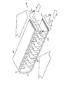
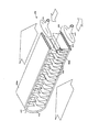
【解決手段】 熱交換器100は、複数のほぼ平行な管部分104A、104Bを含む多経路構成で配置された管102と、管部分104A、104Bに連結した複数のフィン106とを備える。隣接した管部分104A、104Bのフィン106は間隙108をおいて隔てられている。
【選択図】 図1
Description
102 管
104A、104B 管部分
106 フィン
108 間隙
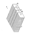
402 管
404A、404B 管部分
406 折り重ねフィン
418 端部移行キャップ
426 折り重ねフィン
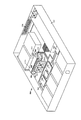
700 電子システム
702 配管
704 熱交換器
730 液体ループ冷却システム
Claims (10)
- 複数のほぼ平行な管部分を含む多経路構成で配置された管と、
前記管部分に連結した複数のフィンと、
を備え、隣接した管部分の前記フィンは間隙をおいて隔てられていることを特徴とする熱交換器。 - 空気流入口および出口穴と、前記入口穴から前記出口穴へ空気を循環させることが可能なファンとを含むシャシと、
前記シャシ内に搭載された複数の部品と、
液体−空気熱交換器と、
を備え、前記液体−空気熱交換器は、複数のほぼ平行な管部分を含む多経路構成で配置された管と、前記管部分に連結した複数のフィンとを備え、隣接した管部分の前記フィンは間隙をおいて隔てられていることを特徴とする電子システム。 - 冷却用流体が循環することができる内部通路を有する配管と、
前記配管に連結し、前記配管を通して前記冷却用流体を圧送することが可能なポンプと、
前記配管に連結した熱交換器と、
を備え、前記熱交換器は、複数のほぼ平行な管部分を含む多経路構成で配置された管と、前記管部分に連結した複数のフィンとを備え、隣接した管部分の前記フィンは間隙をおいて隔てられている特徴とする液体ループ冷却システム。 - 前記配管および前記管内に含まれる前記冷却用流体と、
前記熱交換器に空気を送り込むように構成されたファンと、
前記熱交換器に連結した冷却プレートと、
をさらに備えることを特徴とする請求項3に記載の冷却システム。 - 前記熱交換器は、
長手方向軸および円形断面を有し、密な間隔で、かつ、ほぼ平行な複数の管部分を形成する管と、
前記長手方向軸にほぼ垂直に配置され、前記管部分に連結した前記フィンを形成する密接した間隔のプレートの積重体と、
をさらに備え、前記プレートは、前記隣接した管部分の間の熱伝達をほぼなくすのに十分な間隙が隣接した部分のプレート間に残されるような距離だけ、前記隣接した管部分の方に延びていることを特徴とする請求項1ないし4のいずれか1項に記載の熱交換器またはシステム。 - 前記熱交換器は、
長手方向軸および平坦断面を有し、密な間隔で、かつ、ほぼ平行な複数の管部分を形成する管をさらに備えることを特徴とする請求項1ないし5のいずれか1項に記載の熱交換器またはシステム。 - 前記熱交換器は、
前記平坦断面の管部分に連結した複数の折り重ねフィンをさらに備え、隣接した平坦断面の管部分の前記折り重ねフィンは前記間隙をおいて隔てられており、前記折り重ねフィンは、前記隣接した管部分の間の熱伝達をほぼなくすのに十分な前記間隙が隣接した部分のフィン間に残されるような距離だけ、前記隣接した管部分の方に延びることを特徴とする請求項6に記載の熱交換器またはシステム。 - 前記熱交換器は、
前記平坦断面の管部分に連結し、前記管の前記長手方向軸に沿って、かつ、前記シャシ内の空気流経路における冷却性能を最適化するために、前記管に沿った異なる位置において可変のピッチを有する複数の折り重ねフィンをさらに備えることを特徴とする請求項7に記載の熱交換器またはシステム。 - 前記熱交換器は、
2つの隣接した平坦断面の管を連結し、前記熱交換器が薄いシャシの内部に収まることを可能にするコンパクトな曲線で約180°折り曲がる平坦断面の管端部接合部をさらに備えることを特徴とする請求項6に記載の熱交換器またはシステム。 - 前記熱交換器は、
平坦断面の管部分を、閉ループ冷却システムの円形断面の取り付け具に連結させるように構成された端部移行キャップをさらに備えることを特徴とする請求項6に記載の熱交換器またはシステム。
Applications Claiming Priority (1)
| Application Number | Priority Date | Filing Date | Title |
|---|---|---|---|
| US10/835,955 US6997247B2 (en) | 2004-04-29 | 2004-04-29 | Multiple-pass heat exchanger with gaps between fins of adjacent tube segments |
Publications (2)
| Publication Number | Publication Date |
|---|---|
| JP2005331233A true JP2005331233A (ja) | 2005-12-02 |
| JP2005331233A5 JP2005331233A5 (ja) | 2008-06-05 |
Family
ID=34574906
Family Applications (1)
| Application Number | Title | Priority Date | Filing Date |
|---|---|---|---|
| JP2005129190A Pending JP2005331233A (ja) | 2004-04-29 | 2005-04-27 | 隣接した管部分のフィン間に間隙を有する多経路熱交換器 |
Country Status (3)
| Country | Link |
|---|---|
| US (1) | US6997247B2 (ja) |
| JP (1) | JP2005331233A (ja) |
| GB (1) | GB2413705B (ja) |
Cited By (3)
| Publication number | Priority date | Publication date | Assignee | Title |
|---|---|---|---|---|
| CN100533716C (zh) * | 2006-09-15 | 2009-08-26 | 富准精密工业(深圳)有限公司 | 散热装置 |
| JPWO2012014934A1 (ja) * | 2010-07-27 | 2013-09-12 | 住友軽金属工業株式会社 | 空気調和機用サーペンタイン熱交換器 |
| US10281220B1 (en) * | 2016-08-19 | 2019-05-07 | ZT Group Int'l, Inc. | Heat sink with vapor chamber |
Families Citing this family (27)
| Publication number | Priority date | Publication date | Assignee | Title |
|---|---|---|---|---|
| JP2005191294A (ja) * | 2003-12-25 | 2005-07-14 | Toshiba Corp | 冷却装置および冷却装置を有する電子機器 |
| US7277282B2 (en) * | 2004-12-27 | 2007-10-02 | Intel Corporation | Integrated circuit cooling system including heat pipes and external heat sink |
| US20080000616A1 (en) * | 2006-06-21 | 2008-01-03 | Nobile John R | Heat exchanger and use thereof in showers |
| KR101276819B1 (ko) * | 2006-09-25 | 2013-06-18 | 엘지전자 주식회사 | 건조기 |
| US20080121370A1 (en) * | 2006-11-28 | 2008-05-29 | Foxconn Technology Co., Ltd. | Heat dissipation device with a heat pipe |
| US7372698B1 (en) * | 2006-12-21 | 2008-05-13 | Isothermal Systems Research, Inc. | Electronics equipment heat exchanger system |
| DE102007019206B4 (de) * | 2007-04-24 | 2009-11-26 | Pierburg Gmbh | Wärmeübertragungsvorrichtung |
| US8409743B2 (en) * | 2007-11-28 | 2013-04-02 | Sanyo Electric Co., Ltd. | Battery system with battery cells arranged in array alignment |
| JP5360228B2 (ja) * | 2009-10-16 | 2013-12-04 | 富士通株式会社 | 電子装置および複合電子装置 |
| US8931296B2 (en) | 2009-11-23 | 2015-01-13 | John S. Chen | System and method for energy-saving inductive heating of evaporators and other heat-exchangers |
| CN101806550B (zh) * | 2010-03-24 | 2014-02-19 | 三花控股集团有限公司 | 微通道换热器 |
| CN102235652B (zh) * | 2010-05-06 | 2014-06-18 | 浙江思朗照明有限公司 | 一种风冷液冷组合式散热装置 |
| CN102244011A (zh) * | 2011-06-14 | 2011-11-16 | 东莞市永兴电子科技有限公司 | 水冷式液冷板的制作工艺 |
| US8787013B1 (en) * | 2011-09-19 | 2014-07-22 | Amazon Technologies, Inc. | Carrier with adjustable heat removal elements |
| US20140182829A1 (en) * | 2012-08-09 | 2014-07-03 | Modine Manufacturing Co. | Heat Exchanger Tube Assembly and Method of Making the Same |
| JP6003423B2 (ja) * | 2012-09-07 | 2016-10-05 | 富士通株式会社 | 冷却ユニット及び電子装置 |
| JP6127416B2 (ja) * | 2012-09-07 | 2017-05-17 | 富士通株式会社 | 電子機器 |
| TWD164333S (zh) * | 2013-08-06 | 2014-11-21 | 富士通股份有限公司 | 用於電子元件之散熱器 |
| CN104423503A (zh) * | 2013-08-28 | 2015-03-18 | 英业达科技有限公司 | 服务器 |
| CN104900794B (zh) * | 2015-06-18 | 2018-04-20 | 东莞市闻誉实业有限公司 | Led灯散热结构 |
| CN104934677B (zh) * | 2015-07-01 | 2018-12-04 | 成都众易通科技有限公司 | 具有三角形散热鳍片的交互式天线散热块 |
| CN104900977B (zh) * | 2015-07-01 | 2018-11-13 | 成都众易通科技有限公司 | 交互式天线散热块 |
| EP3236188B1 (en) | 2016-04-18 | 2018-12-19 | Hamilton Sundstrand Corporation | Heat exchangers |
| KR102115906B1 (ko) * | 2017-02-20 | 2020-06-02 | 엘지전자 주식회사 | 제습기 |
| US20190368819A1 (en) * | 2018-05-30 | 2019-12-05 | Johnson Controls Technology Company | Heat exchanger for hvac unit |
| EP3686714A1 (en) | 2019-01-25 | 2020-07-29 | Asetek Danmark A/S | Cooling system including a heat exchanging unit |
| US10925187B1 (en) * | 2019-08-30 | 2021-02-16 | Dell Products, L.P. | Remote heat exchanger arm for direct contact liquid cooling for rack mounted equipment |
Citations (6)
| Publication number | Priority date | Publication date | Assignee | Title |
|---|---|---|---|---|
| JPH06300476A (ja) * | 1993-04-08 | 1994-10-28 | Nippondenso Co Ltd | 熱交換器 |
| JPH11118311A (ja) * | 1997-10-13 | 1999-04-30 | Sumitomo Precision Prod Co Ltd | プレートフィン型素子冷却器 |
| JP2002261222A (ja) * | 2001-03-02 | 2002-09-13 | Sanyo Electric Co Ltd | 半導体素子の冷却装置 |
| JP2003269880A (ja) * | 2002-03-19 | 2003-09-25 | Hitachi Ltd | 熱交換器 |
| JP2004025258A (ja) * | 2002-06-26 | 2004-01-29 | Toyo Radiator Co Ltd | 熱交換器の製造方法 |
| JP2004028470A (ja) * | 2002-06-26 | 2004-01-29 | Toyo Radiator Co Ltd | 熱交換器 |
Family Cites Families (28)
| Publication number | Priority date | Publication date | Assignee | Title |
|---|---|---|---|---|
| BE416338A (ja) * | 1924-06-07 | |||
| GB902011A (en) | 1958-03-06 | 1962-07-25 | Green & Son Ltd | Improvements in or relating to tubular heat exchangers |
| US3877517A (en) | 1973-07-23 | 1975-04-15 | Peerless Of America | Heat exchangers |
| CH565985A5 (ja) | 1974-01-28 | 1975-08-29 | Von Roll Ag | |
| DE2442420C3 (de) | 1974-09-05 | 1979-10-31 | Basf Ag, 6700 Ludwigshafen | Desublimator für die Gewinnung von Sublimationsprodukten, insbesondere von Phthalsäureanhydrid, aus Reaktionsgasen |
| US4256177A (en) | 1978-11-09 | 1981-03-17 | Modine Manufacturing Company | Heat exchanger |
| US4567351A (en) | 1983-08-10 | 1986-01-28 | Matsushita Electric Works, Ltd. | Electric space heater employing a vaporizable heat exchange fluid |
| GB8519942D0 (en) | 1985-08-08 | 1985-09-18 | Baxi Partnership Ltd | Heat exchangers |
| US4778004A (en) * | 1986-12-10 | 1988-10-18 | Peerless Of America Incorporated | Heat exchanger assembly with integral fin unit |
| US5020586A (en) | 1989-09-08 | 1991-06-04 | Hewlett-Packard Company | Air-cooled heat exchanger for electronic circuit modules |
| JPH087247Y2 (ja) * | 1989-10-06 | 1996-03-04 | サンデン株式会社 | 熱交換器 |
| US5131233A (en) | 1991-03-08 | 1992-07-21 | Cray Computer Corporation | Gas-liquid forced turbulence cooling |
| US5293930A (en) | 1992-09-24 | 1994-03-15 | Hewlett-Packard Company | Surface-to-air heat exchanger for electronic devices |
| US6377453B1 (en) | 1999-01-29 | 2002-04-23 | Hewlett-Packard Company | Field replaceable module with enhanced thermal interface |
| US6253839B1 (en) * | 1999-03-10 | 2001-07-03 | Ti Group Automotive Systems Corp. | Refrigeration evaporator |
| US6166907A (en) * | 1999-11-26 | 2000-12-26 | Chien; Chuan-Fu | CPU cooling system |
| US20020117291A1 (en) * | 2000-05-25 | 2002-08-29 | Kioan Cheon | Computer having cooling apparatus and heat exchanging device of the cooling apparatus |
| CA2329408C (en) | 2000-12-21 | 2007-12-04 | Long Manufacturing Ltd. | Finned plate heat exchanger |
| US6496386B2 (en) | 2000-12-22 | 2002-12-17 | Hewlett-Packard Company | Method and system for shielding an externally mounted circuit board from electrostatic discharge and mechanical damage while allowing for heat exchange from heat-producing components of the circuit board through the circuit board shield into an external environment |
| WO2002074032A1 (en) * | 2001-03-02 | 2002-09-19 | Sanyo Electric Co., Ltd. | Electronic device |
| US6351381B1 (en) | 2001-06-20 | 2002-02-26 | Thermal Corp. | Heat management system |
| US6529377B1 (en) | 2001-09-05 | 2003-03-04 | Microelectronic & Computer Technology Corporation | Integrated cooling system |
| US20030102112A1 (en) * | 2001-12-03 | 2003-06-05 | Smithey David W. | Flattened tube heat exchanger made from micro-channel tubing |
| US7165326B2 (en) * | 2001-12-17 | 2007-01-23 | Showa Denko K.K. | Heat exchanger and process for fabricating same |
| US6628520B2 (en) | 2002-02-06 | 2003-09-30 | Hewlett-Packard Development Company, L.P. | Method, apparatus, and system for cooling electronic components |
| KR100459136B1 (ko) * | 2002-08-21 | 2004-12-03 | 엘지전자 주식회사 | 응축식 의류건조기용 응축기의 냉각핀 배열구조 |
| KR20040082571A (ko) * | 2003-03-19 | 2004-09-30 | 엘지전자 주식회사 | 핀-튜브 일체형 열교환기 |
| US7280358B2 (en) * | 2004-04-19 | 2007-10-09 | Hewlett-Packard Development Company, L.P. | Liquid loop with multiple heat exchangers for efficient space utilization |
-
2004
- 2004-04-29 US US10/835,955 patent/US6997247B2/en active Active
-
2005
- 2005-03-29 GB GB0506330A patent/GB2413705B/en not_active Expired - Fee Related
- 2005-04-27 JP JP2005129190A patent/JP2005331233A/ja active Pending
Patent Citations (6)
| Publication number | Priority date | Publication date | Assignee | Title |
|---|---|---|---|---|
| JPH06300476A (ja) * | 1993-04-08 | 1994-10-28 | Nippondenso Co Ltd | 熱交換器 |
| JPH11118311A (ja) * | 1997-10-13 | 1999-04-30 | Sumitomo Precision Prod Co Ltd | プレートフィン型素子冷却器 |
| JP2002261222A (ja) * | 2001-03-02 | 2002-09-13 | Sanyo Electric Co Ltd | 半導体素子の冷却装置 |
| JP2003269880A (ja) * | 2002-03-19 | 2003-09-25 | Hitachi Ltd | 熱交換器 |
| JP2004025258A (ja) * | 2002-06-26 | 2004-01-29 | Toyo Radiator Co Ltd | 熱交換器の製造方法 |
| JP2004028470A (ja) * | 2002-06-26 | 2004-01-29 | Toyo Radiator Co Ltd | 熱交換器 |
Cited By (3)
| Publication number | Priority date | Publication date | Assignee | Title |
|---|---|---|---|---|
| CN100533716C (zh) * | 2006-09-15 | 2009-08-26 | 富准精密工业(深圳)有限公司 | 散热装置 |
| JPWO2012014934A1 (ja) * | 2010-07-27 | 2013-09-12 | 住友軽金属工業株式会社 | 空気調和機用サーペンタイン熱交換器 |
| US10281220B1 (en) * | 2016-08-19 | 2019-05-07 | ZT Group Int'l, Inc. | Heat sink with vapor chamber |
Also Published As
| Publication number | Publication date |
|---|---|
| GB2413705A (en) | 2005-11-02 |
| GB2413705B (en) | 2008-02-13 |
| GB0506330D0 (en) | 2005-05-04 |
| US6997247B2 (en) | 2006-02-14 |
| US20050241812A1 (en) | 2005-11-03 |
Similar Documents
| Publication | Publication Date | Title |
|---|---|---|
| JP2005331233A (ja) | 隣接した管部分のフィン間に間隙を有する多経路熱交換器 | |
| US9936607B2 (en) | Fabricating cooled electronic system with liquid-cooled cold plate and thermal spreader | |
| US9414525B2 (en) | Coolant-cooled heat sink configured for accelerating coolant flow | |
| US8345423B2 (en) | Interleaved, immersion-cooling apparatuses and methods for cooling electronic subsystems | |
| US7411785B2 (en) | Heat-spreading devices for cooling computer systems and associated methods of use | |
| US8739406B2 (en) | Vapor condenser with three-dimensional folded structure | |
| US8913384B2 (en) | Thermal transfer structures coupling electronics card(s) to coolant-cooled structure(s) | |
| US8953317B2 (en) | Wicking vapor-condenser facilitating immersion-cooling of electronic component(s) | |
| EP1738127B1 (en) | Low-profile thermosyphon-based cooling system for computers and other electronic devices | |
| JP2005310152A (ja) | 効率的に空間を利用するための、複数の熱交換器を有する液体ループ | |
| US20180341298A1 (en) | Hub-link liquid cooling system | |
| JP2005317969A (ja) | 柔軟性のあるファンアセンブリを有する液体ループ | |
| JP2005315569A (ja) | 流れを真っ直ぐにするフィンを備えた熱交換器 | |
| US20070242438A1 (en) | Low-Profile Thermosyphon-Based Cooling System for Computers and Other Electronic Devices | |
| JP2005122503A (ja) | 冷却装置およびこれを内蔵した電子機器 | |
| US9795064B2 (en) | Heat exchanger, cooling unit, and electronic device | |
| JP2009532871A (ja) | 冷却装置 | |
| US20070151275A1 (en) | Methods and apparatus for microelectronic cooling using a miniaturized vapor compression system | |
| US20100032141A1 (en) | cooling system utilizing carbon nanotubes for cooling of electrical systems | |
| JP4517962B2 (ja) | 電子機器用冷却装置 | |
| JP2009088051A (ja) | 電子機器用の冷却装置 |
Legal Events
| Date | Code | Title | Description |
|---|---|---|---|
| A521 | Request for written amendment filed |
Free format text: JAPANESE INTERMEDIATE CODE: A523 Effective date: 20080421 |
|
| A621 | Written request for application examination |
Free format text: JAPANESE INTERMEDIATE CODE: A621 Effective date: 20080421 |
|
| A977 | Report on retrieval |
Free format text: JAPANESE INTERMEDIATE CODE: A971007 Effective date: 20100922 |
|
| A131 | Notification of reasons for refusal |
Free format text: JAPANESE INTERMEDIATE CODE: A131 Effective date: 20101005 |
|
| A02 | Decision of refusal |
Free format text: JAPANESE INTERMEDIATE CODE: A02 Effective date: 20110308 |