JP2005299957A - 着火装置 - Google Patents
着火装置 Download PDFInfo
- Publication number
- JP2005299957A JP2005299957A JP2004113233A JP2004113233A JP2005299957A JP 2005299957 A JP2005299957 A JP 2005299957A JP 2004113233 A JP2004113233 A JP 2004113233A JP 2004113233 A JP2004113233 A JP 2004113233A JP 2005299957 A JP2005299957 A JP 2005299957A
- Authority
- JP
- Japan
- Prior art keywords
- header
- conductive
- cap
- ignition circuit
- communication
- Prior art date
- Legal status (The legal status is an assumption and is not a legal conclusion. Google has not performed a legal analysis and makes no representation as to the accuracy of the status listed.)
- Granted
Links
Images
Landscapes
- Feeding, Discharge, Calcimining, Fusing, And Gas-Generation Devices (AREA)
- Air Bags (AREA)
Abstract
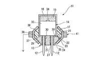
【解決手段】 バス接続用の複数のピン12をヘッダ部本体26に保持してなるヘッダ部13と火薬部15との間に通信点火回路14を配置してなる着火装置11であって、複数のピン12が導電性のヘッダ部本体26と絶縁されて通信点火回路14に電気的に接続され、ヘッダ部本体26が火薬部15および通信点火回路14を覆う導電性のキャップ16に接触させられている。
【選択図】 図1
Description
第1実施形態の着火装置11は、バス接続用の一対のピン12を有するヘッダ部13と、該ヘッダ部13の上側に配置される通信点火回路14と、この通信点火回路14の上側に設けられる火薬部15と、通信点火回路14および火薬部15の全体を囲みヘッダ部13の一部を囲む有底円筒状のキャップ16と、キャップ16のヘッダ部13側に設けられる樹脂モールド17とを有している。
12 ピン
13 ヘッダ部
14 通信点火回路
15 火薬部
16 キャップ
26 ヘッダ部本体
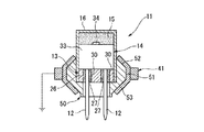
41 取付用部材
50 台部材
Claims (3)
- バス接続用の複数のピンをヘッダ部本体に保持してなるヘッダ部と火薬部との間に通信点火回路を配置してなる着火装置であって、
前記複数のピンが導電性の前記ヘッダ部本体と絶縁されて前記通信点火回路に電気的に接続され、前記ヘッダ部本体が前記火薬部および前記通信点火回路を覆う導電性のキャップに接触させられていることを特徴とする着火装置。 - 車体側に短絡する導電性の取付用部材に、前記ヘッダ部本体が接触状態で係止されることを特徴とする請求項1記載の着火装置。
- 前記ヘッダ部本体および前記キャップに接触状態で固定される導電性の金属材料からなる台部材を有し、該台部材が、車体側に短絡する導電性の取付用部材に接触状態で係止されることを特徴とする請求項1または2記載の着火装置。
Priority Applications (1)
| Application Number | Priority Date | Filing Date | Title |
|---|---|---|---|
| JP2004113233A JP4364709B2 (ja) | 2004-04-07 | 2004-04-07 | 着火装置 |
Applications Claiming Priority (1)
| Application Number | Priority Date | Filing Date | Title |
|---|---|---|---|
| JP2004113233A JP4364709B2 (ja) | 2004-04-07 | 2004-04-07 | 着火装置 |
Publications (2)
| Publication Number | Publication Date |
|---|---|
| JP2005299957A true JP2005299957A (ja) | 2005-10-27 |
| JP4364709B2 JP4364709B2 (ja) | 2009-11-18 |
Family
ID=35331706
Family Applications (1)
| Application Number | Title | Priority Date | Filing Date |
|---|---|---|---|
| JP2004113233A Expired - Fee Related JP4364709B2 (ja) | 2004-04-07 | 2004-04-07 | 着火装置 |
Country Status (1)
| Country | Link |
|---|---|
| JP (1) | JP4364709B2 (ja) |
-
2004
- 2004-04-07 JP JP2004113233A patent/JP4364709B2/ja not_active Expired - Fee Related
Also Published As
| Publication number | Publication date |
|---|---|
| JP4364709B2 (ja) | 2009-11-18 |
Similar Documents
| Publication | Publication Date | Title |
|---|---|---|
| US9711902B2 (en) | Electrical plug connector for a safety restraint system | |
| US20200103207A1 (en) | Igniting unit, especially for an inflator, inflator, airbag module, vehicle safety system and method of manufacturing an igniting unit | |
| US20050126415A1 (en) | Initiator | |
| US7824194B2 (en) | Case with connector and manufacturing method thereof | |
| JP2905758B2 (ja) | 火工式ガス発生器用のセルフロック式2線コネクタ付き点火装置 | |
| KR102440279B1 (ko) | 차량 탑승자 안전 시스템의 에어백 모듈용 와이어링 하니스, 에어백 모듈, 차량 케이블링 및 이러한 종류의 와이어링 하니스를 구비하는 차량 탑승객 안전 시스템 및 제조 방법 | |
| JPH07254471A (ja) | ステアリングコラムの接続器及びこれを備えた自動車用エアバッグ装置 | |
| US6915744B2 (en) | Pyrotechnic initiator with on-board control circuitry | |
| JP4364709B2 (ja) | 着火装置 | |
| US20030150348A1 (en) | Initiator and gas generator | |
| US7686325B2 (en) | Gas generator and device for electrically contacting a gas generator | |
| CN114341589B (zh) | 烟火点火爆管及烟火点火爆管的制造方法 | |
| US7322292B2 (en) | Squib | |
| JP4444717B2 (ja) | 着火装置 | |
| US20060260498A1 (en) | Igniter assembly | |
| US6907827B2 (en) | Pyrotechnic initiator having output can with encapsulation material retention feature | |
| US7211998B2 (en) | Acceleration sensing apparatus | |
| US6650528B2 (en) | Ignition device for a safety system | |
| JP2006250763A (ja) | 温度センサ | |
| JP4397731B2 (ja) | 点火装置 | |
| JP2007139366A (ja) | 点火器、点火器の製造方法及びガス発生器 | |
| CN115428176A (zh) | 压电元件连接结构、车辆及压电元件连接方法 | |
| EP1970663A1 (en) | Ignition device, gas generation device for airbag, and gas generation device for seatbelt pretensioner | |
| KR200387319Y1 (ko) | 에어백용 마운팅 플레이트 조립체 | |
| JP4194928B2 (ja) | 高感度ヒューズ |
Legal Events
| Date | Code | Title | Description |
|---|---|---|---|
| A621 | Written request for application examination |
Free format text: JAPANESE INTERMEDIATE CODE: A621 Effective date: 20061128 |
|
| A977 | Report on retrieval |
Free format text: JAPANESE INTERMEDIATE CODE: A971007 Effective date: 20090326 |
|
| A131 | Notification of reasons for refusal |
Free format text: JAPANESE INTERMEDIATE CODE: A131 Effective date: 20090421 |
|
| A521 | Written amendment |
Free format text: JAPANESE INTERMEDIATE CODE: A523 Effective date: 20090602 |
|
| A131 | Notification of reasons for refusal |
Free format text: JAPANESE INTERMEDIATE CODE: A131 Effective date: 20090630 |
|
| A521 | Written amendment |
Free format text: JAPANESE INTERMEDIATE CODE: A523 Effective date: 20090716 |
|
| TRDD | Decision of grant or rejection written | ||
| A01 | Written decision to grant a patent or to grant a registration (utility model) |
Free format text: JAPANESE INTERMEDIATE CODE: A01 Effective date: 20090811 |
|
| A01 | Written decision to grant a patent or to grant a registration (utility model) |
Free format text: JAPANESE INTERMEDIATE CODE: A01 |
|
| A61 | First payment of annual fees (during grant procedure) |
Free format text: JAPANESE INTERMEDIATE CODE: A61 Effective date: 20090819 |
|
| FPAY | Renewal fee payment (event date is renewal date of database) |
Free format text: PAYMENT UNTIL: 20120828 Year of fee payment: 3 |
|
| R150 | Certificate of patent or registration of utility model |
Free format text: JAPANESE INTERMEDIATE CODE: R150 |
|
| FPAY | Renewal fee payment (event date is renewal date of database) |
Free format text: PAYMENT UNTIL: 20120828 Year of fee payment: 3 |
|
| FPAY | Renewal fee payment (event date is renewal date of database) |
Free format text: PAYMENT UNTIL: 20130828 Year of fee payment: 4 |
|
| FPAY | Renewal fee payment (event date is renewal date of database) |
Free format text: PAYMENT UNTIL: 20140828 Year of fee payment: 5 |
|
| LAPS | Cancellation because of no payment of annual fees |