JP2005299957A - Ignition device - Google Patents
Ignition device Download PDFInfo
- Publication number
- JP2005299957A JP2005299957A JP2004113233A JP2004113233A JP2005299957A JP 2005299957 A JP2005299957 A JP 2005299957A JP 2004113233 A JP2004113233 A JP 2004113233A JP 2004113233 A JP2004113233 A JP 2004113233A JP 2005299957 A JP2005299957 A JP 2005299957A
- Authority
- JP
- Japan
- Prior art keywords
- header
- conductive
- cap
- ignition circuit
- communication
- Prior art date
- Legal status (The legal status is an assumption and is not a legal conclusion. Google has not performed a legal analysis and makes no representation as to the accuracy of the status listed.)
- Granted
Links
Images
Landscapes
- Air Bags (AREA)
- Feeding, Discharge, Calcimining, Fusing, And Gas-Generation Devices (AREA)
Abstract
【課題】 通信点火回路を配置するための内部スペースを広く確保できる着火装置の提供。
【解決手段】 バス接続用の複数のピン12をヘッダ部本体26に保持してなるヘッダ部13と火薬部15との間に通信点火回路14を配置してなる着火装置11であって、複数のピン12が導電性のヘッダ部本体26と絶縁されて通信点火回路14に電気的に接続され、ヘッダ部本体26が火薬部15および通信点火回路14を覆う導電性のキャップ16に接触させられている。
【選択図】 図1PROBLEM TO BE SOLVED: To provide an ignition device capable of ensuring a wide internal space for arranging a communication ignition circuit.
An ignition device (11) in which a communication ignition circuit (14) is arranged between a header part (13) holding a plurality of bus connecting pins (12) in a header part body (26) and an explosive part (15). The pin 12 is insulated from the conductive header portion body 26 and is electrically connected to the communication ignition circuit 14. The header portion body 26 is brought into contact with the conductive cap 16 covering the explosive portion 15 and the communication ignition circuit 14. ing.
[Selection] Figure 1
Description
本発明は、自動車用エアバッグやシートベルトプリテンショナ等の火薬を用いるシステムで使用される着火装置に関する。 The present invention relates to an ignition device used in a system using explosives such as an automobile airbag or a seat belt pretensioner.
近年、一台の自動車に採用されるエアバッグやシートベルトプリテンショナ等の数は増加傾向にあり、その結果、これらを作動させるための着火装置の数も増える傾向にある。このような着火装置の数の増大に対応するため、複数の着火装置をバス接続させ、コントロールユニットからの通信コマンドで点火制御を行うことにより、ハーネスの削減を図る技術がある(例えば、特許文献1参照)。 In recent years, the number of airbags and seat belt pretensioners employed in a single automobile has been increasing, and as a result, the number of ignition devices for operating them has also been increasing. In order to cope with such an increase in the number of ignition devices, there is a technique for reducing the number of harnesses by connecting a plurality of ignition devices to a bus and performing ignition control with a communication command from a control unit (for example, Patent Documents). 1).
このようなシステムに対応するために個々の点火装置に着火素子に加えて通信点火回路を設ける必要があるが、出願人は通信回路と点火回路と着火素子とを一つのICに納める技術を開発し先の出願を行っている(特願2002−376637号)。 In order to cope with such a system, it is necessary to provide a communication ignition circuit in addition to the ignition element in each ignition device, but the applicant has developed a technology for putting the communication circuit, the ignition circuit and the ignition element in one IC. A previous application has been filed (Japanese Patent Application No. 2002-376637).
さらに、出願人は構造の簡略化と通信点火回路搭載スペースの拡大を可能にするべくバス接続用のピンを有するヘッダ部と火薬部との間に通信点火回路を配置してなる着火装置を開発し先の出願を行っている(特願2003−419479号)。 Furthermore, the applicant has developed an ignition device in which a communication ignition circuit is arranged between a header part having a bus connection pin and an explosive part in order to simplify the structure and expand the communication ignition circuit mounting space. A previous application has been filed (Japanese Patent Application No. 2003-419479).
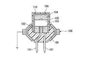
ところで、先の出願の着火装置等において想定されていたものは、図3に示すように、一方のピン101を導電性のヘッダ部本体102に導通可能に保持し、他方のピン101をヘッダ部本体102に絶縁材料103を介して絶縁状態で保持するようになっており、さらにヘッダ部本体102が火薬部104および通信点火回路105を覆う導電性のキャップ106に接触させられる構造となっている。
ところで、図3に示す構造では、一方のピン101が導電性のヘッダ部本体102に電気的導通状態にあるため、車体側に短絡されている導電性の取付用部材108に取り付ける際に、ヘッダ部本体102と取付用部材108とを絶縁するべくこれらの間に絶縁性の樹脂モールド109が必要となる。ヘッダ部本体102にピン101を保持する保持長さを確保する必要があることから、この樹脂モールド109を設ける分はヘッダ部本体102を取付用部材108に対し離す必要があり、しかも樹脂モールド109は強度を確保するために厚みを確保する必要があることからも、通信点火回路105を配置するための内部スペースが狭くなってしまうことになる。
By the way, in the structure shown in FIG. 3, since one
また、一方のピン101はヘッダ部本体102を介して導電性のキャップ106に電気的導通状態にあるため、車体側に短絡されている導電性の取付用部材108に取り付ける際に、キャップ106を取付用部材108に接触させてはならず、そのため、キャップ106を絶縁性の樹脂材料からなるカバー110で覆っていた。このようにカバー110で覆う必要があると、その分も、通信点火回路105を配置するための内部スペースが狭くなってしまうことになる。
In addition, since one
したがって、本発明は、通信点火回路を配置するための内部スペースを広く確保できる着火装置の提供を目的とする。 Therefore, an object of the present invention is to provide an ignition device that can secure a wide internal space for disposing a communication ignition circuit.
上記目的を達成するために、請求項1に係る発明は、バス接続用の複数のピン(例えば実施形態におけるピン12)をヘッダ部本体(例えば実施形態におけるヘッダ部本体26)に保持してなるヘッダ部(例えば実施形態におけるヘッダ部13)と火薬部(例えば実施形態における火薬部15)との間に通信点火回路(例えば実施形態における通信点火回路14)を配置してなる着火装置(例えば実施形態における着火装置11)であって、前記複数のピンが導電性の前記ヘッダ部本体と絶縁されて前記通信点火回路に電気的に接続され、前記ヘッダ部本体が前記火薬部および前記通信点火回路を覆う導電性のキャップ(例えば実施形態におけるキャップ16)に接触させられていることを特徴としている。
In order to achieve the above object, the invention according to claim 1 is configured such that a plurality of bus connection pins (for example, the
請求項2に係る発明は、請求項1に係る発明において、車体側に短絡する導電性の取付用部材(例えば実施形態における取付用部材41)に、前記ヘッダ部本体が接触状態で係止されることを特徴としている。
The invention according to claim 2 is the invention according to claim 1, wherein the header portion main body is locked in contact with a conductive attachment member that is short-circuited to the vehicle body side (for example, the
請求項3に係る発明は、請求項1または2に係る発明において、前記ヘッダ部本体および前記キャップに接触状態で固定される導電性の金属材料からなる台部材(例えば実施形態における台部材50)を有し、該台部材が、車体側に短絡する導電性の取付用部材に接触状態で係止されることを特徴としている。
The invention according to claim 3 is the invention according to claim 1 or 2, wherein the base member is made of a conductive metal material fixed in contact with the header portion main body and the cap (for example, the
請求項1に係る発明によれば、複数のピンが導電性のヘッダ部本体と絶縁されて通信点火回路に電気的に接続されているため、車体側に短絡されている導電性の取付用部材とヘッダ部本体との間に絶縁性の樹脂モールドが不要となり、ヘッダ部本体を取付用部材に近づけることができる。また、樹脂モールドの代わりに強度的に有利な金属製の台部材等を使用できることになるため、強度的にも問題なくヘッダ部本体を取付用部材に近づけることができる。したがって、通信点火回路を配置するための内部スペースを広く確保できる。また、ヘッダ部本体が火薬部および通信点火回路を覆う導電性のキャップに接触させられていても、ピンとキャップとが電気的に導通してしまうことがない。したがって、車体側に短絡されている導電性の取付用部材に取り付ける際に、キャップを取付用部材に接触させても良く、よって、キャップを絶縁材料からなるカバーで覆う必要がなくなる。この点からも、通信点火回路を配置するための内部スペースを広く確保できる。しかも、導電性のキャップを車体側に短絡されている導電性の取付用部材に接触させることができるため、電磁波ノイズをキャップから取付用部材を介して車体側に流すことができる。 According to the first aspect of the present invention, since the plurality of pins are insulated from the conductive header portion main body and electrically connected to the communication ignition circuit, the conductive mounting member short-circuited to the vehicle body side An insulating resin mold is not required between the header part body and the header part body, and the header part body can be brought close to the mounting member. Moreover, since a metal base member or the like advantageous in strength can be used instead of the resin mold, the header portion main body can be brought close to the mounting member without any problem in strength. Therefore, a wide internal space for arranging the communication ignition circuit can be secured. Moreover, even if the header part main body is made to contact the conductive cap which covers an explosive part and a communication ignition circuit, a pin and a cap will not electrically conduct. Therefore, when attaching to the conductive attachment member that is short-circuited on the vehicle body side, the cap may be brought into contact with the attachment member, so that it is not necessary to cover the cap with a cover made of an insulating material. Also from this point, a wide internal space for disposing the communication ignition circuit can be secured. In addition, since the conductive cap can be brought into contact with the conductive mounting member that is short-circuited to the vehicle body side, electromagnetic wave noise can flow from the cap to the vehicle body side through the mounting member.
請求項2に係る発明によれば、車体側に短絡する導電性の取付用部材に、ヘッダ部本体が接触状態で係止されるため、ヘッダ部本体を取付用部材にさらに近づけることになる。したがって、通信点火回路を配置するための内部スペースをさらに広く確保できる。 According to the second aspect of the present invention, since the header portion main body is locked in contact with the conductive attachment member that is short-circuited to the vehicle body side, the header portion main body is further brought closer to the attachment member. Therefore, a wider internal space for disposing the communication ignition circuit can be secured.
請求項3に係る発明によれば、ヘッダ部本体およびキャップに接触状態で固定される導電性の金属材料からなる台部材を有するため、強度的に問題なくヘッダ部本体を取付用部材に近づけることができる。 According to the invention of claim 3, since the base member made of a conductive metal material fixed in contact with the header body and the cap is provided, the header body is brought close to the mounting member with no problem in strength. Can do.
本発明の第1実施形態の着火装置を図1を参照して以下に説明する。
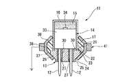
第1実施形態の着火装置11は、バス接続用の一対のピン12を有するヘッダ部13と、該ヘッダ部13の上側に配置される通信点火回路14と、この通信点火回路14の上側に設けられる火薬部15と、通信点火回路14および火薬部15の全体を囲みヘッダ部13の一部を囲む有底円筒状のキャップ16と、キャップ16のヘッダ部13側に設けられる樹脂モールド17とを有している。
An ignition device according to a first embodiment of the present invention will be described below with reference to FIG.
The
ヘッダ部13は、最も通信点火回路14側に第1円筒面部21が形成され、第1円筒面部21の通信点火回路14とは反対側に外径方向に広がる段面部22が形成され、段面部22の第1円筒面部21とは反対側に第1円筒面部21よりも大径の第2円筒面部23が形成され、この第2円筒面部23の段面部22とは反対側に第2円筒面部23から離れるほど小径となるテーパ面部24が形成され、さらにこのテーパ面部24の第2円筒面部23とは反対側に第1円筒面部21よりも小径の第3円筒面部25が形成された外径側形状の導電性の金属材料からなるヘッダ部本体26を有している。このヘッダ部本体26には、中心軸線から相反方向に等距離離れて中心軸線に沿う貫通穴27が一対形成されている。
The
ヘッダ部13は、一対つまり複数の導電性のピン12を有しており、ヘッダ部本体26の各貫通穴27の中心位置に各ピン12がヘッダ部本体26に接触することがないようにガラスハーメチック等の絶縁保持材30を介して保持されている。
The
通信点火回路14は、ヘッダ部本体26の第1円筒面部21と同径の略短円柱状をなす回路本体33の軸線方向における一側に着火素子34が設けられており、回路本体33の軸線方向における逆側には各ピン12に電気的に接続される図示せぬ端子部が設けられている。
The
そして、通信点火回路14は回路本体33を第1円筒面部21と同軸に配置しかつ図示せぬ端子部に各ピン12を接触させた状態でヘッダ部13に接合固定される。これにより複数のピン12がすべて導電性のヘッダ部本体26と絶縁されて通信点火回路14に電気的に接続される。
The
その後、導電性の金属材料からなる有底円筒状のキャップ16の底部側に所定量の火薬を入れた後、キャップ16に、上記のように一体化されたヘッダ部13および通信点火回路14を通信点火回路14側から挿入し、ヘッダ部13については第1円筒面部21までを嵌合させるようにして通信点火回路14側で火薬を押し固める。つまり、火薬を圧填して火薬部15を形成する。このとき、ヘッダ部本体26が火薬部15および通信点火回路14を覆う導電性のキャップ16に接触させられる。この状態でヘッダ部本体26にキャップ16が溶接される。
Then, after putting a predetermined amount of explosives into the bottom side of the bottomed
そして、キャップ16のヘッダ部13側とヘッダ部13とにかけて外径側に樹脂モールド17が設けられて、バス接続用のピン12を有するヘッダ部13と火薬部15との間に通信点火回路14を配置してなる着火装置11となる。
A
ここで、樹脂モールド17はヘッダ部本体26のテーパ面部24と連続する第1テーパ面部37とこの第1テーパ面部37の大径側に設けられる円筒面部38とこの円筒面部38の第1テーパ面部37とは反対側に設けられ円筒面部38から離れるほど小径となる第2テーパ面部39とを有する外径側形状をなしている。
Here, the
このような着火装置11の樹脂モールド17およびヘッダ部本体26の外径側に取付用部材41が加締めおよび溶接の少なくともいずれか一方で取り付けられ、これにより着火装置11は取付用部材41に取り付けられる。ここで、取付用部材41は車体側に短絡される導電性の金属材料で形成されており、加締められることでヘッダ部本体26のテーパ面部24と、樹脂モールド17の第1テーパ面部37、円筒面部38および第2テーパ面部39とに接触する。このとき、車体側に短絡する導電性の取付用部材41に、ヘッダ部本体26が接触状態で係止される。
The
以上に述べた第1実施形態によれば、複数のピン12が導電性のヘッダ部本体26と絶縁されて通信点火回路14に電気的に接続されているため、車体側に短絡されている導電性の取付用部材41とヘッダ部本体26との間に絶縁性の樹脂モールドが不要となり、ヘッダ部本体26を取付用部材41に近づけることができ、具体的には、ヘッダ部本体26を取付用部材41に接触させることができる。しかも、強度的に有利な金属製のヘッダ部本体26をキャップ16から突出させてこのヘッダ部本体26を取付用部材41に接触係止させるため、強度的にも問題ない。したがって、通信点火回路14を配置するための内部スペースを軸線方向に広く確保できる。
According to the first embodiment described above, since the plurality of
また、ヘッダ部本体26が火薬部15および通信点火回路14を覆う導電性のキャップ16に接触させられてもピン12とキャップ16とが電気的に導通してしまうことがない。したがって、車体側に短絡されている導電性の取付用部材41に取り付ける際に、キャップ16を取付用部材41に接触させても良く、よって、キャップ16を絶縁材料からなるカバーで覆う必要がなくなる。したがって、通信点火回路14を配置するための内部スペースを径方向にも広く確保できる。
Further, even if the
しかも、導電性のキャップ16およびヘッダ部本体26を車体側に短絡されている導電性の取付用部材41に接触させることができるため、電磁波ノイズをキャップ16およびヘッダ部本体26から取付用部材41を介して車体側に流すことができる。
In addition, since the
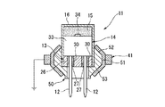
本発明の第2実施形態の着火装置11を図2を参照して第1実施形態との相違部分を中心に以下に説明する。なお、第1実施形態と同様の部分には同一の符号を付しその説明は略す。
The
第2実施形態の着火装置11は、ヘッダ部本体26をキャップ16から突出させず、突出するヘッダ部本体26および樹脂モールド17の代わりに、導電性の金属材料からなる台部材50を用いている。つまり、ヘッダ部本体26はキャップ16に全体が挿入される短円柱状をなしており、ヘッダ部本体26のキャップ16から露出する部分とキャップ16のヘッダ部本体26側とを覆うようにして台部材50がキャップ16に嵌合されている。
The
ここで、台部材50は、軸線方向における中間部に円筒面部51が形成され、円筒面部51の両側に円筒面部51から離れるほど小径となる第1テーパ面部52および第2テーパ面部53を有する外径側形状をなしている。
Here, the
このような第2実施形態の着火装置11は、台部材50の外径側に取付用部材41が加締められることになり、その結果、取付用部材41に取り付けられる。ここで、取付用部材41は、加締められることで台部材50の第1テーパ面部52、円筒面部51および第2テーパ面部53に接触する。つまり、ヘッダ部本体26およびキャップ16に接触状態で固定される導電性の金属材料からなる台部材50が、車体側に短絡する導電性の取付用部材41に接触状態で係止される。
The
以上に述べた第2実施形態によれば、複数のピン12が導電性のヘッダ部本体26と絶縁されて通信点火回路14に電気的に接続されているため、車体側に短絡されている導電性の取付用部材41とヘッダ部本体26との間に絶縁性の樹脂モールドが不要となり、樹脂モールドの代わりに強度的に有利な金属製の台部材50を使用することになることから、強度的にも問題なくヘッダ部本体26を取付用部材41に近づけることができる。したがって、通信点火回路14を配置するための内部スペースを軸線方向に広く確保できる。
According to the second embodiment described above, since the plurality of
また、第1実施形態と同様、ヘッダ部本体26が火薬部15および通信点火回路14を覆う導電性のキャップ16に接触させられてもピン12とキャップ16とが電気的に導通してしまうことがないことから、キャップ16を絶縁材料からなるカバーで覆う必要がなくなって、通信点火回路14を配置するための内部スペースを径方向にも広く確保できる。
Similarly to the first embodiment, even if the
しかも、導電性のキャップ16および台部材50を車体側に短絡されている導電性の取付用部材41に接触させることができるため、電磁波ノイズをキャップ16および台部材50から取付用部材41を介して車体側に流すことができる。
Moreover, since the
11 着火装置
12 ピン
13 ヘッダ部
14 通信点火回路
15 火薬部
16 キャップ
26 ヘッダ部本体
41 取付用部材
50 台部材
DESCRIPTION OF
Claims (3)
前記複数のピンが導電性の前記ヘッダ部本体と絶縁されて前記通信点火回路に電気的に接続され、前記ヘッダ部本体が前記火薬部および前記通信点火回路を覆う導電性のキャップに接触させられていることを特徴とする着火装置。 An ignition device in which a communication ignition circuit is arranged between a header part and a gunpowder part that hold a plurality of pins for bus connection in a header part body,
The plurality of pins are insulated from the conductive header part body and electrically connected to the communication ignition circuit, and the header part body is brought into contact with a conductive cap that covers the explosive part and the communication ignition circuit. An ignition device characterized by that.
It has a base member made of a conductive metal material fixed in contact with the header body and the cap, and the base member is locked in contact with a conductive mounting member that is short-circuited to the vehicle body side. The ignition device according to claim 1 or 2, characterized in that:
Priority Applications (1)
| Application Number | Priority Date | Filing Date | Title |
|---|---|---|---|
| JP2004113233A JP4364709B2 (en) | 2004-04-07 | 2004-04-07 | Ignition device |
Applications Claiming Priority (1)
| Application Number | Priority Date | Filing Date | Title |
|---|---|---|---|
| JP2004113233A JP4364709B2 (en) | 2004-04-07 | 2004-04-07 | Ignition device |
Publications (2)
| Publication Number | Publication Date |
|---|---|
| JP2005299957A true JP2005299957A (en) | 2005-10-27 |
| JP4364709B2 JP4364709B2 (en) | 2009-11-18 |
Family
ID=35331706
Family Applications (1)
| Application Number | Title | Priority Date | Filing Date |
|---|---|---|---|
| JP2004113233A Expired - Fee Related JP4364709B2 (en) | 2004-04-07 | 2004-04-07 | Ignition device |
Country Status (1)
| Country | Link |
|---|---|
| JP (1) | JP4364709B2 (en) |
-
2004
- 2004-04-07 JP JP2004113233A patent/JP4364709B2/en not_active Expired - Fee Related
Also Published As
| Publication number | Publication date |
|---|---|
| JP4364709B2 (en) | 2009-11-18 |
Similar Documents
| Publication | Publication Date | Title |
|---|---|---|
| US8661977B2 (en) | Shaped feed-through element with contact rod soldered in | |
| US9711902B2 (en) | Electrical plug connector for a safety restraint system | |
| US20200103207A1 (en) | Igniting unit, especially for an inflator, inflator, airbag module, vehicle safety system and method of manufacturing an igniting unit | |
| EP1491848A1 (en) | Initiator | |
| US7824194B2 (en) | Case with connector and manufacturing method thereof | |
| JP2905758B2 (en) | Ignition device with self-locking two-wire connector for pyrotechnic gas generators | |
| KR102440279B1 (en) | Wiring harness for airbag module of vehicle occupant safety system, airbag module, vehicle cabling and vehicle occupant safety system and manufacturing method having this kind of wiring harness | |
| JPH07254471A (en) | Connection equipment of steering column and air bag device for car with this | |
| JP2005216827A (en) | Electric wire terminal terminal and manufacturing method thereof | |
| US6915744B2 (en) | Pyrotechnic initiator with on-board control circuitry | |
| JP4364709B2 (en) | Ignition device | |
| US20030150348A1 (en) | Initiator and gas generator | |
| US7686325B2 (en) | Gas generator and device for electrically contacting a gas generator | |
| JP4444717B2 (en) | Ignition device | |
| US20060260498A1 (en) | Igniter assembly | |
| US6907827B2 (en) | Pyrotechnic initiator having output can with encapsulation material retention feature | |
| US7211998B2 (en) | Acceleration sensing apparatus | |
| US6650528B2 (en) | Ignition device for a safety system | |
| JP2006250763A (en) | Temperature sensor | |
| JP4397731B2 (en) | Ignition device | |
| JP3115619U (en) | Igniter | |
| CN115428176A (en) | Piezoelectric element connection structure, vehicle, and piezoelectric element connection method | |
| EP1970663A1 (en) | Ignition device, gas generation device for airbag, and gas generation device for seatbelt pretensioner | |
| KR200387319Y1 (en) | airbags mounting plate assembly | |
| JP4194928B2 (en) | High sensitivity fuse |
Legal Events
| Date | Code | Title | Description |
|---|---|---|---|
| A621 | Written request for application examination |
Free format text: JAPANESE INTERMEDIATE CODE: A621 Effective date: 20061128 |
|
| A977 | Report on retrieval |
Free format text: JAPANESE INTERMEDIATE CODE: A971007 Effective date: 20090326 |
|
| A131 | Notification of reasons for refusal |
Free format text: JAPANESE INTERMEDIATE CODE: A131 Effective date: 20090421 |
|
| A521 | Written amendment |
Free format text: JAPANESE INTERMEDIATE CODE: A523 Effective date: 20090602 |
|
| A131 | Notification of reasons for refusal |
Free format text: JAPANESE INTERMEDIATE CODE: A131 Effective date: 20090630 |
|
| A521 | Written amendment |
Free format text: JAPANESE INTERMEDIATE CODE: A523 Effective date: 20090716 |
|
| TRDD | Decision of grant or rejection written | ||
| A01 | Written decision to grant a patent or to grant a registration (utility model) |
Free format text: JAPANESE INTERMEDIATE CODE: A01 Effective date: 20090811 |
|
| A01 | Written decision to grant a patent or to grant a registration (utility model) |
Free format text: JAPANESE INTERMEDIATE CODE: A01 |
|
| A61 | First payment of annual fees (during grant procedure) |
Free format text: JAPANESE INTERMEDIATE CODE: A61 Effective date: 20090819 |
|
| FPAY | Renewal fee payment (event date is renewal date of database) |
Free format text: PAYMENT UNTIL: 20120828 Year of fee payment: 3 |
|
| R150 | Certificate of patent or registration of utility model |
Free format text: JAPANESE INTERMEDIATE CODE: R150 |
|
| FPAY | Renewal fee payment (event date is renewal date of database) |
Free format text: PAYMENT UNTIL: 20120828 Year of fee payment: 3 |
|
| FPAY | Renewal fee payment (event date is renewal date of database) |
Free format text: PAYMENT UNTIL: 20130828 Year of fee payment: 4 |
|
| FPAY | Renewal fee payment (event date is renewal date of database) |
Free format text: PAYMENT UNTIL: 20140828 Year of fee payment: 5 |
|
| LAPS | Cancellation because of no payment of annual fees |