JP2005299850A - Integrated double-pipe - Google Patents
Integrated double-pipe Download PDFInfo
- Publication number
- JP2005299850A JP2005299850A JP2004119204A JP2004119204A JP2005299850A JP 2005299850 A JP2005299850 A JP 2005299850A JP 2004119204 A JP2004119204 A JP 2004119204A JP 2004119204 A JP2004119204 A JP 2004119204A JP 2005299850 A JP2005299850 A JP 2005299850A
- Authority
- JP
- Japan
- Prior art keywords
- pipe
- double
- tube
- integrated
- bodies
- Prior art date
- Legal status (The legal status is an assumption and is not a legal conclusion. Google has not performed a legal analysis and makes no representation as to the accuracy of the status listed.)
- Pending
Links
Images
Classifications
-
- B—PERFORMING OPERATIONS; TRANSPORTING
- B21—MECHANICAL METAL-WORKING WITHOUT ESSENTIALLY REMOVING MATERIAL; PUNCHING METAL
- B21C—MANUFACTURE OF METAL SHEETS, WIRE, RODS, TUBES OR PROFILES, OTHERWISE THAN BY ROLLING; AUXILIARY OPERATIONS USED IN CONNECTION WITH METAL-WORKING WITHOUT ESSENTIALLY REMOVING MATERIAL
- B21C23/00—Extruding metal; Impact extrusion
- B21C23/02—Making uncoated products
- B21C23/04—Making uncoated products by direct extrusion
- B21C23/08—Making wire, bars, tubes
-
- B—PERFORMING OPERATIONS; TRANSPORTING
- B21—MECHANICAL METAL-WORKING WITHOUT ESSENTIALLY REMOVING MATERIAL; PUNCHING METAL
- B21C—MANUFACTURE OF METAL SHEETS, WIRE, RODS, TUBES OR PROFILES, OTHERWISE THAN BY ROLLING; AUXILIARY OPERATIONS USED IN CONNECTION WITH METAL-WORKING WITHOUT ESSENTIALLY REMOVING MATERIAL
- B21C35/00—Removing work or waste from extruding presses; Drawing-off extruded work; Cleaning dies, ducts, containers, or mandrels
- B21C35/02—Removing or drawing-off work
- B21C35/023—Work treatment directly following extrusion, e.g. further deformation or surface treatment
- B21C35/026—Removing sections from the extruded work, e.g. removing a strip to create an open profile
-
- B—PERFORMING OPERATIONS; TRANSPORTING
- B21—MECHANICAL METAL-WORKING WITHOUT ESSENTIALLY REMOVING MATERIAL; PUNCHING METAL
- B21C—MANUFACTURE OF METAL SHEETS, WIRE, RODS, TUBES OR PROFILES, OTHERWISE THAN BY ROLLING; AUXILIARY OPERATIONS USED IN CONNECTION WITH METAL-WORKING WITHOUT ESSENTIALLY REMOVING MATERIAL
- B21C37/00—Manufacture of metal sheets, bars, wire, tubes or like semi-manufactured products, not otherwise provided for; Manufacture of tubes of special shape
- B21C37/06—Manufacture of metal sheets, bars, wire, tubes or like semi-manufactured products, not otherwise provided for; Manufacture of tubes of special shape of tubes or metal hoses; Combined procedures for making tubes, e.g. for making multi-wall tubes
- B21C37/15—Making tubes of special shape; Making tube fittings
- B21C37/28—Making tube fittings for connecting pipes, e.g. U-pieces
- B21C37/29—Making branched pieces, e.g. T-pieces
Abstract
Description
本発明は、複数の管体を集合させてリブで一体化した一体型複管に関するものである。 The present invention relates to an integrated double tube in which a plurality of tubes are assembled and integrated with a rib.
例えば、車両用空調装置では、冷媒や温媒などの供給配管・帰還配管を並列に配置することがよくある(例えば、特許文献1参照)。このような並列に複数の配管を配置する場合、例えば、特許文献2に開示されるような二重管を用いると、配管レイアウトを簡素化できるので、好ましいとされている。
しかしながら、このような外管内に内管を貫通させた二重管では、端末部において内側流路と外側流路とを分岐するために、分岐用のコネクタ部材(特許文献2中符号24で示す部材)を二重管の端末部に接続する必要があり、どうしても分岐部の加工コストが高くなりがちであった。 However, in such a double pipe in which the inner pipe is passed through the outer pipe, a branching connector member (indicated by reference numeral 24 in Patent Document 2) is used to branch the inner flow path and the outer flow path at the terminal portion. Member) must be connected to the end portion of the double pipe, and the processing cost of the branch portion inevitably tends to be high.
本発明は、上記事情を考慮し、並列に配された複数の管体を備えながらも、配管端末部を接続する際の分岐加工コストがかからない一体型複管を提供することを目的とする。 In consideration of the above circumstances, an object of the present invention is to provide an integrated double pipe that is provided with a plurality of pipe bodies arranged in parallel but does not incur branching processing costs when connecting pipe terminal portions.
請求項1の発明は、各々が管壁を独立させ且つ互いに他の管壁の外側に位置するように並列に配置された管体と、隣接する管体を連結するリブとを備え、押出加工または引抜加工により一様な断面の一体成形品として形成されてなることを特徴とする。 The invention of claim 1 includes a tube body arranged in parallel so that each of the tube walls is independent and located outside of the other tube wall, and a rib for connecting adjacent tube bodies, and an extrusion process Alternatively, it is formed as an integrally molded product having a uniform cross section by drawing.
請求項2の発明は、請求項1に記載の一体型複管であって、前記各管体の断面が、円を複数に分割した際の各扇形(半円も含む)となるように形成されており、全管体を、隣接するもの同士の平面壁の間に隙間をあけた状態で前記円内に集合させてなることを特徴とする。 The invention according to claim 2 is the integrated double pipe according to claim 1, wherein the cross section of each tubular body is formed into a sector shape (including a semicircle) when a circle is divided into a plurality of parts. It is characterized in that all the tubular bodies are assembled in the circle with a gap between the plane walls of adjacent ones.
請求項1の発明によれば、並列に配置した複数の管体をリブで一体化した押出加工または引抜加工により製造される複管であるので、1本の配管のように取り扱うことができ、配管レイアウトの簡素化が図れる。また、端末加工の際には、リブを切断することによって簡単に管体を分離できるので、分岐コネクタが不要となり分岐加工コストが低減される。 According to the invention of claim 1, since it is a double pipe manufactured by an extrusion process or drawing process in which a plurality of pipe bodies arranged in parallel are integrated with ribs, it can be handled like a single pipe, Piping layout can be simplified. Further, when processing the terminal, the pipe body can be easily separated by cutting the rib, so that a branch connector is not required, and the branch processing cost is reduced.
請求項2の発明によれば、各管体の断面を扇形に形成して円内に集合させて外観を円形管の体裁に見せているので、1本の円管のように取り扱うことができる。しかも、外周側の壁が集まることで円筒壁を形成するので、曲げ加工する際に角形管のような特定方向に対する脆弱性が生じることがなく曲げ加工しやすい。また、隣接する管体の平面壁の間に隙間を設けているので、各管体内を流れる流体間の管壁を通しての熱伝導を抑制することができる。 According to the second aspect of the present invention, the cross sections of the respective tubular bodies are formed in a fan shape and gathered in a circle to show the appearance of a circular tube, so that it can be handled like a single circular tube. . Moreover, since the cylindrical wall is formed by gathering the walls on the outer peripheral side, it is easy to bend without bending in a specific direction like a square tube when bending. Moreover, since the clearance gap is provided between the plane walls of an adjacent tube body, the heat conduction through the tube wall between the fluids which flow through each tube body can be suppressed.
以下、本発明の実施形態を図面を参照して説明する。 Hereinafter, embodiments of the present invention will be described with reference to the drawings.
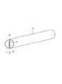
図1は第1実施形態の一体型複管10を示す斜視図である。この一体型複管10は、押出加工または引抜加工により一様な断面の一体成形管として形成されおり、各々が管壁を独立させ且つ互いに他の管壁の外側に位置するように並列に配置された2つの管体11、12と、隣接する管体11、12を連結するリブ18と、を備えている。
FIG. 1 is a perspective view showing an integrated
各管体11、12の断面はそれぞれ半円状に形成されている。また、複管10は、2つの管体11、12を平面壁の間に隙間17をあけた状態で、元の円内に集合させたような形態をなしている。リブ18は、両管体11、12の平面壁の幅方向の両端同士を繋ぐように配置されている。これによりリブ18は両管体11、12の円弧壁に連続した位置にある。
The cross sections of the
このように並列に配置した2つの管体11、12をリブ18で一体化し、押出加工または引抜加工により製造してあるので、1本の配管のように取り扱うことができ、配管レイアウトの簡素化が図れる。
Since the two
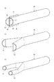
また、端末加工の際には、図2(a)、(b)に示すように切断治具Kでリブ18を切断することによって簡単に管体11、12を分離することができるので、内管と外管よりなる二重管のように分岐コネクタを使用する必要がなく、分岐加工コストを低減できる。分岐した管体11、12の端末が半円状のままでは不都合の場合は、(c)に示すように端末部を円形管状に成形し直せばよい。
Further, when the terminal is processed, the
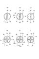
図3は各実施形態の複管の断面の例を示す。 FIG. 3 shows an example of a cross section of the double tube of each embodiment.
(a)〜(c)は各管体の断面が半円(1/2円)の場合の例、(d)〜(f)は各管体の断面が1/4円の場合の例を示す。
(a)の実施形態の複管10は、上述した例と同じ断面のものである。
(A)-(c) is an example when the cross section of each tube is a semicircle (1/2 circle), (d)-(f) is an example when the cross section of each tube is 1/4 circle. Show.
The
(b)の実施形態の複管20は、2つの断面半円状の管体21、22の平面壁同士を繋ぐリブ28の位置を、(a)のように外周側ではなく、それより少し中心寄りに設定した断面のものである。これにより2つのリブ28の間の隙間27aと、2つのリブ28の各外側の隙間27bと、ができる。
In the
(c)の実施形態の複管30は、2つの断面半円状の管体31、32の平面壁同士を繋ぐリブ38の位置を、円の中心部に設定した断面のものである。これにより、リブ38の両側に2つの隙間37ができる。
The
(d)の実施形態の複管40は、各管体41〜44の断面を円を4分割した際の各1/4円の扇形となるように形成し、全管体41〜44を、隣接するもの同士の平面壁の間に隙間47をあけた状態で円内に集合させてなるものである。この場合、隙間47は十字状をなし、リブ48の位置は外周端に設定されている。
The
(e)の実施形態の複管50は、4つの管体51〜54の平面壁同士を繋ぐリブ58の位置を、(d)のように外周端ではなくそれより少し中心寄りに設定した断面のものである。これにより、各リブ58の内側に十字の隙間57aができ、各リブ58の外側にスリット状の隙間57bができる。
The
(f)の実施形態の複管60は、4つの管体61〜64の平面壁同士を繋ぐリブ68の位置を、円の中心部に十文字に設定した断面のものである。これにより、リブ68の外側に4つの隙間67ができる。
The double pipe 60 of the embodiment of (f) has a cross section in which the positions of the
いずれの実施形態の場合も、リブ18、28、38、48、58、68を切断することにより、容易に管体11,12、21,22、31,32、41〜44、51〜54、61〜64を分離することができる。従って、分岐加工コストがかからない。
In any of the embodiments, the
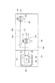
図3は上述した複管の使用場所の例を示す図で、車両100の平面レイアウトを概略的に示している。
FIG. 3 is a diagram showing an example of the use place of the above-described double pipe, and schematically shows a planar layout of the
図において、101はエンジンルーム、102は車室である。エンジンルーム101内にはエンジン105が配置され、エンジン105の前方にラジエータ106が配置されている。エンジン105とラジエータ106は、冷却水配管107、108で繋がれ、エンジン105とラジエータ106間に冷却水が強制循環されるようになっている。
In the figure, 101 is an engine room, and 102 is a passenger compartment. An
車室102側には、前席用の温風吹出ユニット110と後席用の温風吹出ユニット120とが設けられている。各温風吹出ユニット110、120は、ファン113、123からの風を車室102内に吹き出すダクト111、121内にヒータコア112、122を配設したもので、ヒータコア112、133にエンジンを冷却して得た温水(温媒)を循環させることにより、車室102内に温風を吹き出すことができるようになっている。
On the
従って、各ヒータコア112、122には、エンジンの冷却水配管107、108から分岐した往管131、133と復管132、134が接続されている。
Therefore, the
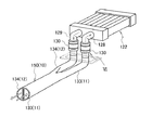
前席用の温風吹出ユニット110の場合は、往管131と復管132の長さが短くて済むが、後席用の温風吹出ユニット120の場合は、往管133と復管134の長さが長くなる。そこで、この長く配管する必要のある部分に、本発明の実施形態の一体型複管150が使われている。このように複管150を利用することにより、配管レイアウトの簡素化が図れる。
In the case of the warm
図4は同部分の具体的な配管例を示している。 FIG. 4 shows a specific piping example of the same part.
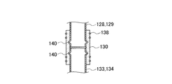
ヒータコア122の入口管128に、往管133として複管150(10)の中の一方の管体11を接続し、出口管129に、復管134として複管150(10)の中の他方の管体12を接続している。このように管体11、12を別々の配管に接続するために、複管10の端末を上述の手順で分岐加工し、図6に示すようにゴムホース130とクランプ138を用いて入口管128と出口管129に接続している。この際、接続すべき管の端部に抜け止め用の膨出部140を形成するのがよい。
One
10、20、30、40、50、60、150…一体型複管
11,12、21,22、31,32、41〜44、51〜54、61〜64…管体
17、27a,27b、37、47、57a,57b、67…隙間
18、28、38、48、58、68…リブ
10, 20, 30, 40, 50, 60, 150 ... Integrated
Claims (2)
前記各管体(11,12、21,22、31,32、41〜44、51〜54、61〜64)の断面が、円を複数に分割した際の各扇形となるように形成されており、全管体(11,12、21,22、31,32、41〜44、51〜54、61〜64)を、隣接するもの同士の平面壁の間に隙間(17、27a,27b、37、47、57a,57b、67)をあけた状態で、前記円内に集合させてなることを特徴とする一体型複管(10、20、30、40、50、60)。
The integrated double pipe according to claim 1,
Each tube (11, 12, 21, 22, 31, 32, 41-44, 51-54, 61-64) is formed to have a sector shape when a circle is divided into a plurality of sections. All the tubular bodies (11, 12, 21, 22, 31, 32, 41-44, 51-54, 61-64) between the adjacent flat walls (17, 27a, 27b, 37, 47, 57a, 57b, 67) are integrated in the circle with the open state (10, 20, 30, 40, 50, 60).
Priority Applications (1)
| Application Number | Priority Date | Filing Date | Title |
|---|---|---|---|
| JP2004119204A JP2005299850A (en) | 2004-04-14 | 2004-04-14 | Integrated double-pipe |
Applications Claiming Priority (1)
| Application Number | Priority Date | Filing Date | Title |
|---|---|---|---|
| JP2004119204A JP2005299850A (en) | 2004-04-14 | 2004-04-14 | Integrated double-pipe |
Publications (1)
| Publication Number | Publication Date |
|---|---|
| JP2005299850A true JP2005299850A (en) | 2005-10-27 |
Family
ID=35331618
Family Applications (1)
| Application Number | Title | Priority Date | Filing Date |
|---|---|---|---|
| JP2004119204A Pending JP2005299850A (en) | 2004-04-14 | 2004-04-14 | Integrated double-pipe |
Country Status (1)
| Country | Link |
|---|---|
| JP (1) | JP2005299850A (en) |
Cited By (4)
| Publication number | Priority date | Publication date | Assignee | Title |
|---|---|---|---|---|
| CN102072598A (en) * | 2011-01-21 | 2011-05-25 | 海尔集团公司 | Air-returning pipe component and manufacturing method |
| CN105127238A (en) * | 2015-10-19 | 2015-12-09 | 河北欧通有色金属制品有限公司 | Machining method for D-shaped copper pipes and D-shaped copper pipes |
| CN108398024A (en) * | 2018-05-28 | 2018-08-14 | 安徽诚铭热能技术有限公司 | A kind of sintering ignition furnace air curtain isolating device |
| WO2022168534A1 (en) * | 2021-02-05 | 2022-08-11 | 日本サーモスタット株式会社 | Tubing for vehicle cooling circuit and cooling circuit using same |
-
2004
- 2004-04-14 JP JP2004119204A patent/JP2005299850A/en active Pending
Cited By (6)
| Publication number | Priority date | Publication date | Assignee | Title |
|---|---|---|---|---|
| CN102072598A (en) * | 2011-01-21 | 2011-05-25 | 海尔集团公司 | Air-returning pipe component and manufacturing method |
| CN102072598B (en) * | 2011-01-21 | 2016-03-30 | 海尔集团公司 | Air-returning pipe component and preparation method thereof |
| CN105127238A (en) * | 2015-10-19 | 2015-12-09 | 河北欧通有色金属制品有限公司 | Machining method for D-shaped copper pipes and D-shaped copper pipes |
| CN105127238B (en) * | 2015-10-19 | 2017-07-28 | 河北欧通有色金属制品有限公司 | A kind of processing method of D types copper pipe |
| CN108398024A (en) * | 2018-05-28 | 2018-08-14 | 安徽诚铭热能技术有限公司 | A kind of sintering ignition furnace air curtain isolating device |
| WO2022168534A1 (en) * | 2021-02-05 | 2022-08-11 | 日本サーモスタット株式会社 | Tubing for vehicle cooling circuit and cooling circuit using same |
Similar Documents
| Publication | Publication Date | Title |
|---|---|---|
| US7117933B2 (en) | Core structure of integral heat-exchanger | |
| JP3803282B2 (en) | Secondary refrigerant air conditioner | |
| JPH04187990A (en) | Heat exchanging device | |
| JP2006250521A (en) | Heat radiation fin for heat exchanger and heat exchanger | |
| JP5706665B2 (en) | Reinforcement structure of heat exchanger | |
| JP2005214545A (en) | Heat exchanger | |
| JP2005299850A (en) | Integrated double-pipe | |
| JP2011089710A (en) | Refrigerant heat exchanger | |
| JP2006189249A (en) | Double pipe heat exchanger | |
| JP3664783B2 (en) | Condenser | |
| JP2001133187A (en) | Multiple heat exchanger | |
| JP2007322060A (en) | Heat exchanger | |
| JP6111024B2 (en) | Heat exchanger | |
| JPH06257975A (en) | Heat exchanging device and heat dissipating body therefor | |
| JP5706666B2 (en) | Reinforcement structure of heat exchanger | |
| ATE330197T1 (en) | RADIATOR ARRANGEMENT | |
| KR100602438B1 (en) | Double pipe and it make use of ventilation apparatus | |
| JP3658801B2 (en) | Double heat exchanger | |
| KR101362222B1 (en) | Heat Exchanger | |
| CN216048304U (en) | Inflation board heat exchanger | |
| KR20160015549A (en) | Heat exchanger | |
| JP2002195774A (en) | Air heat exchanger | |
| JP2007333311A (en) | Heat exchanger | |
| JP2008106933A (en) | Branch pipe and air conditioner using branch pipe | |
| JP2017219294A (en) | Heat exchanger for vehicle, and manufacturing method of heat exchanger for vehicle |