JP2005298926A - Vapor deposition equipment - Google Patents
Vapor deposition equipment Download PDFInfo
- Publication number
- JP2005298926A JP2005298926A JP2004118450A JP2004118450A JP2005298926A JP 2005298926 A JP2005298926 A JP 2005298926A JP 2004118450 A JP2004118450 A JP 2004118450A JP 2004118450 A JP2004118450 A JP 2004118450A JP 2005298926 A JP2005298926 A JP 2005298926A
- Authority
- JP
- Japan
- Prior art keywords
- vapor deposition
- unit
- container
- storage container
- valve body
- Prior art date
- Legal status (The legal status is an assumption and is not a legal conclusion. Google has not performed a legal analysis and makes no representation as to the accuracy of the status listed.)
- Granted
Links
- 238000007740 vapor deposition Methods 0.000 title claims abstract description 140
- 239000000463 material Substances 0.000 claims abstract description 283
- 238000001704 evaporation Methods 0.000 claims abstract description 115
- 230000008020 evaporation Effects 0.000 claims abstract description 100
- 238000004891 communication Methods 0.000 claims abstract description 99
- 238000013459 approach Methods 0.000 claims abstract description 4
- 238000010438 heat treatment Methods 0.000 claims description 53
- 238000001514 detection method Methods 0.000 claims description 31
- 230000008021 deposition Effects 0.000 claims description 24
- 238000001816 cooling Methods 0.000 claims description 16
- 239000011364 vaporized material Substances 0.000 claims description 10
- 230000004044 response Effects 0.000 claims description 3
- 238000009834 vaporization Methods 0.000 claims description 3
- 230000008016 vaporization Effects 0.000 claims description 3
- 239000000758 substrate Substances 0.000 description 37
- 239000011521 glass Substances 0.000 description 32
- 239000010408 film Substances 0.000 description 17
- 230000000694 effects Effects 0.000 description 7
- 239000000498 cooling water Substances 0.000 description 6
- 230000003028 elevating effect Effects 0.000 description 6
- 238000005259 measurement Methods 0.000 description 6
- 239000011368 organic material Substances 0.000 description 6
- 230000001105 regulatory effect Effects 0.000 description 6
- 238000012986 modification Methods 0.000 description 5
- 230000004048 modification Effects 0.000 description 5
- 238000012546 transfer Methods 0.000 description 5
- 238000000605 extraction Methods 0.000 description 4
- 239000011882 ultra-fine particle Substances 0.000 description 4
- 230000008878 coupling Effects 0.000 description 3
- 238000010168 coupling process Methods 0.000 description 3
- 238000005859 coupling reaction Methods 0.000 description 3
- 230000009471 action Effects 0.000 description 2
- 230000003247 decreasing effect Effects 0.000 description 2
- 239000011261 inert gas Substances 0.000 description 2
- 238000003780 insertion Methods 0.000 description 2
- 230000037431 insertion Effects 0.000 description 2
- 239000004973 liquid crystal related substance Substances 0.000 description 2
- 239000010409 thin film Substances 0.000 description 2
- 238000003466 welding Methods 0.000 description 2
- 230000001174 ascending effect Effects 0.000 description 1
- 239000002826 coolant Substances 0.000 description 1
- 239000013078 crystal Substances 0.000 description 1
- 230000006866 deterioration Effects 0.000 description 1
- 238000010586 diagram Methods 0.000 description 1
- 238000007599 discharging Methods 0.000 description 1
- 239000007789 gas Substances 0.000 description 1
- 230000005525 hole transport Effects 0.000 description 1
- 238000004519 manufacturing process Methods 0.000 description 1
- 230000002093 peripheral effect Effects 0.000 description 1
- 230000009467 reduction Effects 0.000 description 1
- 238000012360 testing method Methods 0.000 description 1
- 230000007704 transition Effects 0.000 description 1
Images
Landscapes
- Physical Vapour Deposition (AREA)
Abstract
【課題】蒸発材料のロスをより効果的に軽減する。
【解決手段】材料収納容器21を加熱して材料を蒸発させる蒸発部4aと、前記蒸発材料を被蒸着部材に付着させる蒸着部3aと、蒸発材料を蒸発部4aから蒸着部3aに導く連通部9aとを備えた蒸着装置であって、連通部9aに設けられた弁孔41dと、材料収納容器21を連通部9aに嵌合するとともに弁孔41dに対して接近離間方向に往復移動させる容器進退装置20と、材料収納容器21に設けられて弁孔41dに接近または当接し連通部9aにおける蒸発材料の流量を調整可能開閉弁部42とを備えた流量調整装置40を設け、容器進退装置20により材料収納容器21を連通部9aに嵌合されることにより、材料収納容器21と連通部9aとが略気密状態に接続される。
【選択図】 図2
The loss of evaporation material is more effectively reduced.
An evaporation unit 4a that heats a material storage container 21 to evaporate the material, a vapor deposition unit 3a that adheres the evaporation material to an evaporation target member, and a communication unit that guides the evaporation material from the evaporation unit 4a to the vapor deposition unit 3a. 9a is a vapor deposition apparatus including a valve hole 41d provided in the communication portion 9a and a container that fits the material storage container 21 into the communication portion 9a and reciprocates in the approaching and separating direction with respect to the valve hole 41d. A flow rate adjusting device 40 provided with an advancing / retreating device 20 and an opening / closing valve portion 42 provided in the material storage container 21 so as to approach or contact the valve hole 41d and adjust the flow rate of the evaporating material in the communicating portion 9a is provided. The material storage container 21 and the communication part 9a are connected in a substantially airtight state by fitting the material storage container 21 to the communication part 9a by 20.
[Selection] Figure 2
Description
本発明は、真空雰囲気または不活性ガス雰囲気中で、たとえば有機ELディスプレイなどの画像表示部を製造するための蒸着装置に関するものである。 The present invention relates to a vapor deposition apparatus for manufacturing an image display unit such as an organic EL display in a vacuum atmosphere or an inert gas atmosphere.
近年、ディスプレイの薄型化が進み、この種のディスプレイとしては、液晶ディスプレイの実用化が非常に進んでいる。この液晶画面については、バックライトを必要とするもので、視野範囲、消費電力などの点で難点があり、最近、自発光性の有機EL方式のディスプレイが注目されている。 In recent years, thinning of displays has progressed, and as this type of display, liquid crystal displays have been put to practical use. This liquid crystal screen requires a backlight and has difficulties in view range, power consumption, etc. Recently, a self-luminous organic EL display has been attracting attention.
ところで、有機ELディスプレイの基本構造は、ガラス基板上に、陽極(透明電極)を配置し、この上に、ホール輸送層および発光層が順番に配置され、さらに陰極が配置されたものであり、少なくとも、前記発光層については、有機材料が蒸着により形成されている。 By the way, the basic structure of the organic EL display is an arrangement in which an anode (transparent electrode) is arranged on a glass substrate, a hole transport layer and a light emitting layer are arranged in this order, and a cathode is further arranged. At least for the light emitting layer, an organic material is formed by vapor deposition.
そして、基板上に、蒸着により薄膜を形成する場合、真空容器内に有機材料の蒸発源を配置しておき、真空状態で蒸発源を加熱し、その蒸気を同じく真空容器内に配置された基板の表面に付着させることにより薄膜が形成されていた。 When a thin film is formed on the substrate by vapor deposition, an organic material evaporation source is placed in the vacuum vessel, the evaporation source is heated in a vacuum state, and the vapor is also placed in the vacuum vessel. A thin film was formed by adhering to the surface.
ところで、特許文献1に示されたガスデポジション装置は、超微粒子形成室(蒸発室)から膜形成室(蒸着室)に超微粒子を搬送する搬送管を設け、超微粒子が搬送管に付着しないように加熱装置を設けたものである。
By the way, the gas deposition apparatus shown in
また特許文献2に開示された蒸着装置は、真空チャンバの下部に、真空弁を有する有機EL材料の材料放出口が2個配置されるとともに、これら各放出口の下部に材料を加熱するセル(蒸発源)がそれぞれ配置されたセル室(蒸発室)が設けられたものである。
特許文献1では、加熱蒸発された蒸発材料は、一旦超微粒子形成室内に充満され搬送管を介して膜形成室に送られるため、特にガラス基板や材料収納容器の交換時などに材料のロスが生じやすく、特に高価な有機EL材料では、コストの無駄が生じる。また特許文献2でも、セル室が小さいが、セル交換時にセル室で材料のロスは発生する。
In
そこで、本発明は、例えば蒸発材料のロスをより効果的に軽減することができる蒸着装置を提供することを目的とする。 Then, an object of this invention is to provide the vapor deposition apparatus which can reduce the loss of evaporation material more effectively, for example.
請求項1記載の発明は、材料収納容器を加熱して材料を蒸発させる蒸着部と、前記蒸発材料を被蒸着部材に付着させる蒸着部と、前記蒸発材料を蒸発部から蒸着部に導く連通部とを備えた蒸着装置であって、前記連通部に設けられた協働調整部と、前記材料収納容器を連通部に嵌合するとともに前記協働調整部に対して接近離間方向に往復移動させる容器進退手段と、前記材料収納容器に設けられて協働調整部に接近または当接し連通部における蒸発材料の流量を調整可能な開度調整部とを備えた流量調整手段を設け、前記容器進退手段により材料収納容器を連通部に嵌合されることにより、材料収納容器と連通部とが略気密状態に接続されるものである。
The invention according to
請求項2記載の発明は、蒸発用容器内に蒸発部を、蒸着用容器内に蒸着部をそれぞれ独立して設け、前記蒸発用容器と蒸着用容器とを接続する接続部材に、少なくとも前記蒸発用容器側に容器進退手段の進退方向に沿いかつ材料収納容器と連通部とが略気密状態に接続される部位を有する連通部を形成したものである。 According to a second aspect of the present invention, an evaporation section is provided in the evaporation container, and an evaporation section is provided independently in the evaporation container, and at least the evaporation member is connected to a connecting member that connects the evaporation container and the evaporation container. A communication portion is formed on the container side along a direction in which the container advancing / retreating means extends and the material storage container and the communication portion are connected in a substantially airtight state.
請求項3記載の発明は、協働調整部は、連通部に弁孔を形成する弁孔形成部材により構成され、開度調整部は、前記弁孔に接近離間して前記弁孔の流路断面積を縮小調整可能な開閉弁部により構成されたものである。 According to a third aspect of the present invention, the coordinating adjustment part is configured by a valve hole forming member that forms a valve hole in the communication part, and the opening degree adjustment part approaches and separates from the valve hole. It is composed of an on-off valve portion whose cross-sectional area can be reduced and adjusted.
請求項4記載の発明は、上下方向に形成された連通部を有し、協働調整部は、前記連通部に形成された弁孔部と、前記弁孔部に昇降自在に配置されて自重により閉止する第1弁体とで構成され、開度調整部は、前記第1弁体を押し上げて弁孔部を開放可能な第1弁体作動部により構成されたものである。 According to a fourth aspect of the present invention, there is provided a communication portion formed in the vertical direction, and the cooperative adjustment portion is disposed in the communication portion so as to be movable up and down in the valve hole portion, and is self-weighted. The opening degree adjusting part is constituted by a first valve body actuating part capable of pushing up the first valve body and opening the valve hole part.
請求項5記載の発明は、横方向に形成された連通部を有し、協働調整部は、前記連通部に形成された弁孔部と、付勢部材により弁孔部に押し付けられて弁孔部を閉止する第2弁体とを有し、開度調整部は、前記第2弁体を付勢部材に抗して押し戻し弁孔部を開放可能な第2弁体作動部により構成されたものである。
The invention according to
請求項6記載の発明は、協働調整部は、連通部に周方向の軸心周りに揺動自在に設けられ非作用時に該連通部を開放状態とする複数の第3弁体により構成され、開度調整部は、前記第3弁体を揺動して連通部を開度調整可能な第3弁体作動部により構成されたものである。 According to a sixth aspect of the present invention, the coordinating adjustment portion is configured by a plurality of third valve bodies that are provided in the communication portion so as to be swingable around a circumferential axis, and that open the communication portion when not operating. The opening degree adjusting unit is constituted by a third valve body operating unit that swings the third valve body and can adjust the opening degree of the communicating part.
請求項7記載の発明は、開度調整部は、材料収納容器の開口部に揺動自在に設けられて非作用時に開口部を開放する複数の第4弁体により構成され、協働調整部は、第4弁体を揺動して材料収納容器の開口部の開度調整可能な第4弁体作動部材により構成されたものである。 According to the seventh aspect of the present invention, the opening degree adjusting portion is configured by a plurality of fourth valve bodies that are swingably provided in the opening portion of the material storage container and open the opening portion when not operating, and the cooperative adjusting portion. Is constituted by a fourth valve body actuating member capable of adjusting the opening degree of the opening of the material container by swinging the fourth valve body.
請求項8記載の発明は、協働調整部は、連通部に直交する軸心周りに回動自在に配置され非作用時に該連通部を略閉止状態とする第5弁体により構成され、開度調整部は、第5弁体を開動して連通部を開度調整可能な第5弁体作動部により構成されたものである。 According to an eighth aspect of the present invention, the coordinating adjustment portion is configured by a fifth valve body that is rotatably disposed around an axis perpendicular to the communication portion, and that closes the communication portion when not in operation. The degree adjusting unit is configured by a fifth valve body operating unit that opens the fifth valve body and can adjust the opening of the communication unit.
請求項9記載の発明は、開度調整部は、材料収納容器の開口部に直交する軸心周りに回動自在に配置され非作用時に該開口部を略閉止状態とする第6弁体により構成され、協働調整部は、第6弁体を開動して容器の開口部を開度調整可能な第6弁体作動部で構成されたものである。
The invention according to
請求項10記載の発明は、材料収納容器内の蒸着材料を加熱する材料加熱手段を設け、容器進退手段による材料収納容器に移動量を検出する進退量検出手段を設け、前記進退量検出手段の検出信号に対応して材料加熱手段を制御する蒸着制御部を有する蒸着制御装置を設けたものである。 According to a tenth aspect of the present invention, there is provided a material heating means for heating the vapor deposition material in the material storage container, and an advance / retreat amount detection means for detecting a movement amount is provided in the material storage container by the container advance / retreat means. A vapor deposition control device having a vapor deposition control unit that controls the material heating means in response to the detection signal is provided.
請求項11記載の発明は、蒸着部に被蒸着部材への蒸発材料の付着量を検出する付着量検出手段を設け、蒸着制御部は、前記付着量検出手段の検出信号に対応して前記容器進退手段を操作するように構成されたものである。 According to an eleventh aspect of the present invention, the vapor deposition unit is provided with an adhesion amount detection means for detecting the adhesion amount of the evaporation material to the vapor deposition member, and the vapor deposition control unit corresponds to the detection signal of the adhesion amount detection means. It is configured to operate the advance / retreat means.
請求項12記載の発明は、蒸着制御装置は、材料収納容器の移動量に対応して、連通部に材料収納容器が気密状態で接続される位置と、連通部における蒸発材料の流量と、材料加熱温度とを記憶する記憶部を具備し、蒸着制御部は、進退量検出手段の検出信号により前記記憶部のデータに基いて材料加熱手段を制御するように構成されたものである。 According to the twelfth aspect of the present invention, the vapor deposition control device corresponds to the amount of movement of the material storage container, the position where the material storage container is connected to the communication part in an airtight state, the flow rate of the evaporation material in the communication part, the material A storage unit for storing the heating temperature is provided, and the vapor deposition control unit is configured to control the material heating unit based on the data of the storage unit based on the detection signal of the advance / retreat amount detection unit.
請求項13記載の発明は、材料収納容器内の蒸着材料を冷却する材料冷却手段を設け、蒸着制御部は、進退量検出手段の検出信号により記憶部のデータに基いて材料冷却手段を制御するように構成されたものである。 According to a thirteenth aspect of the present invention, there is provided a material cooling means for cooling the vapor deposition material in the material storage container, and the vapor deposition control section controls the material cooling means based on the data of the storage section by the detection signal of the advance / retreat amount detection means. It is comprised as follows.
請求項1記載の発明によれば、容器進退手段により材料収納容器を連通部に嵌合することにより、材料収納容器と連通部とが略気密状態に接続されるので、材料収納容器内から蒸発する蒸発材料が連通部から直接蒸着部に導入され、蒸発材料が蒸発部内に充満することがない。したがって、蒸発材料を有効に活用でき、被蒸着部材や材料収納容器の交換時における材料ロスを低減することができる。また材料収納容器が連通部に嵌入される動作に連続する進退動作で、材料収納容器の開度調整部と協働調整部とで連通部における蒸発材料の流量を調整することができ、容器進退手段により、材料収納容器の気密性の確保と、蒸発材料の流量調整とを兼用して行うことができる。 According to the first aspect of the present invention, the material storage container and the communication portion are connected in a substantially airtight state by fitting the material storage container to the communication portion by the container advancing / retreating means. The evaporating material to be introduced is directly introduced into the vapor deposition part from the communicating part, and the evaporating material does not fill the evaporating part. Therefore, the evaporation material can be used effectively, and the material loss at the time of exchanging the deposition target member and the material storage container can be reduced. Further, the flow rate of the evaporation material in the communication portion can be adjusted by the opening adjustment portion and the cooperative adjustment portion of the material storage container by the forward / backward movement operation that is continuous with the operation in which the material storage container is inserted into the communication portion. By means, it is possible to perform both the securing of the airtightness of the material storage container and the adjustment of the flow rate of the evaporation material.
請求項2記載の発明によれば、蒸発部と蒸着部とをそれぞれ独立した容器内に設け、これら容器間を接続部材により連通したので、特に容器内の容量を削減して、被蒸着部材や材料収納容器の交換時における蒸発材料のロスを低減することができる。また排気に要する時間を短縮できて作業性を向上させることができ、蒸発部と蒸着部のレイアウトの自由度を高めることができる。 According to the second aspect of the present invention, the evaporation section and the vapor deposition section are provided in independent containers, and the containers are communicated with each other by the connecting member. It is possible to reduce the loss of the evaporation material when the material container is replaced. Further, the time required for exhaust can be shortened, workability can be improved, and the degree of freedom in the layout of the evaporation part and the vapor deposition part can be increased.
請求項3記載の発明によれば、容器進退手段により材料収納容器を連通部に嵌入させて進退させ、開閉弁部を弁孔形成部材の弁孔に接近離間させることにより流路断面積を縮小調整して連通部における蒸発材料の流量を効果的に調整することができる。
According to the invention of
請求項4記載の発明によれば、容器進退手段により材料収納容器を連通部に嵌合させ、材料収納容器の第1弁体作動部により、連通部を閉止する第1弁体を押し上げて弁孔部を開放することにより、材料収納容器から蒸着部に蒸発材料を送り、連通部における蒸発材料の流量を効果的に調整することができる。
According to the invention of
請求項5記載の発明によれば、容器進退手段により材料収納容器を横方向の連通部に嵌合させて進退させ、材料収納容器の第2弁体作動部により、連通部を閉止する第2弁体を付勢部材に抗して押し戻し弁孔部を開放することにより、材料収納容器から蒸着部に蒸発材料を送り、連通部における蒸発材料の流量を効果的に調整することができる。 According to the fifth aspect of the present invention, the material storage container is fitted to the lateral communication portion by the container advancing / retracting means to advance and retreat, and the second valve body operating portion of the material storage container closes the communication portion. By opening the valve hole portion against the biasing member against the urging member, the evaporation material can be sent from the material storage container to the vapor deposition portion, and the flow rate of the evaporation material in the communication portion can be effectively adjusted.
請求項6記載の発明によれば、容器進退手段により材料収納容器を連通部に嵌合させて進退させ、材料収納容器の第3弁体作動部により、連通部を第3弁体を揺動して連通部の開度を調整することにより、材料収納容器から蒸着部に蒸発材料を送り、連通部における蒸発材料の流量を効果的に調整することができる。 According to the sixth aspect of the present invention, the material storage container is fitted to the communication portion by the container advancing / retreating means to advance and retreat, and the communication portion is swung by the third valve body operating portion of the material storage container. By adjusting the opening of the communication part, the evaporation material can be sent from the material storage container to the vapor deposition part, and the flow rate of the evaporation material in the communication part can be effectively adjusted.
請求項7記載の発明によれば、容器進退手段により材料収納容器を連通部に嵌合させて進退させ、連通部に設けられた第4弁体作動部により、材料収納容器で開口部を開放・閉止する第4弁体を揺動して開口部の開度(連通部の開度)を調整することにより、材料収納容器から蒸着部に蒸発材料を送り、連通部における蒸発材料の流量を効果的に調整することができる。 According to the seventh aspect of the present invention, the material storage container is fitted into the communication portion by the container advancing / retreating means to advance and retreat, and the opening is opened by the material storage container by the fourth valve body operating portion provided in the communication portion. -Evaporating material is sent from the material storage container to the vapor deposition part by swinging the fourth valve body to be closed and adjusting the opening degree of the opening part (opening degree of the communication part). It can be adjusted effectively.
請求項8記載の発明によれば、容器進退手段により材料収納容器を連通部に嵌合させて進退させ、材料収納容器の第5弁体作動部材により、連通部を略閉止状態とする第5弁体を開動して連通部を開度調整することにより、材料収納容器から蒸着部に蒸発材料を送り、連通部における蒸発材料の流量を効果的に調整することができる。 According to the eighth aspect of the present invention, the material storage container is fitted to the communication portion by the container advancing / retracting means and advanced / retracted, and the communication portion is substantially closed by the fifth valve body operating member of the material storage container. By opening the valve body and adjusting the opening of the communication part, the evaporation material can be sent from the material storage container to the vapor deposition part, and the flow rate of the evaporation material in the communication part can be effectively adjusted.
請求項9記載の発明によれば、容器進退手段により材料収納容器を連通部に嵌合させて進退させ、連通部に設けられた第6弁体作動部により、材料収納容器の開口部を略閉止状態とする第6弁体を回動して容器の開口部の開度調整することにより、材料収納容器から蒸着部に蒸発材料を送り、連通部における蒸発材料の流量を効果的に調整することができる。 According to the ninth aspect of the present invention, the material storage container is fitted to the communicating portion by the container advancing / retracting means and advanced / retracted, and the opening of the material storing container is substantially reduced by the sixth valve body operating portion provided in the communicating portion. By rotating the sixth valve body in the closed state and adjusting the opening degree of the opening of the container, the evaporation material is sent from the material storage container to the vapor deposition part, and the flow rate of the evaporation material in the communication part is effectively adjusted. be able to.
請求項10記載の発明によれば、蒸着制御部により、材料収納容器の進退量に基いて、材料収納容器と連通部との気密状態を確保した後、材料加熱手段により予備加熱から本加熱に自動的に移行することができ、蒸着開始動作の自動化を図ることができる。 According to the tenth aspect of the present invention, the vapor deposition control unit secures an airtight state between the material storage container and the communication part based on the amount of advancement and retreat of the material storage container, and then the material heating means changes from the preliminary heating to the main heating. It is possible to shift automatically and to automate the vapor deposition start operation.
請求項11記載の発明によれば、蒸着制御部により、蒸発材料の付着量に基いて、進退手段を介して連通部における蒸発材料の流量を調整でき、またこの蒸発材料の流量を極めて小さくした状態で被蒸着部材の交換作業を開始することができる。 According to the eleventh aspect of the present invention, the vapor deposition control unit can adjust the flow rate of the evaporation material in the communicating portion via the advancing / retreating unit based on the amount of the evaporation material, and the flow rate of the evaporation material is extremely reduced. In this state, the work for replacing the vapor deposition member can be started.
請求項12記載の発明によれば、記憶部のデータ、すなわち材料収納容器の移動量に対応する、材料収納容器の連通部の気密確保位置と、蒸発材料の流量と、材料加熱温度とに基いて、被蒸着部材の交換作業や材料収納容器を交換して材料を追加する作業を自動化することができ、被蒸着部材の交換時に蒸発材料の流量を絞ったり、材料加熱を停止することで、材料のロスを軽減することができる。 According to the twelfth aspect of the present invention, based on the data in the storage unit, that is, the airtight securing position of the communicating part of the material storage container, the flow rate of the evaporation material, and the material heating temperature corresponding to the movement amount of the material storage container. In addition, it is possible to automate the work of replacing the vapor deposition member or replacing the material container and adding the material, and by reducing the flow rate of the evaporation material when replacing the vapor deposition member, or by stopping the material heating, Material loss can be reduced.
請求項13記載の発明によれば、被蒸着部材の交換時に、材料を冷却することで、蒸発を速やかに停止させて材料ロスを軽減することができる。 According to the thirteenth aspect of the present invention, the material loss can be reduced by quickly stopping the evaporation by cooling the material when the deposition target member is replaced.
[実施の形態1]
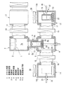
以下、本発明の実施の形態1に係る蒸着装置を、図1〜図4に基づき説明する。本実施の形態1に係る蒸着装置は、有機ELディスプレイの表示部を製造する場合、すなわち有機材料からなる蒸発材料を下方からガラス基板1の表面(下面)に吹付けて蒸着させるアッパーデポジションタイプである。
[Embodiment 1]
Hereinafter, the vapor deposition apparatus which concerns on
この蒸着装置は、図1に示すように、ガラス基板(被蒸着部材)1が、その蒸着面が下方となるように、水平方向で挿入され保持具2に保持される蒸着部3aを形成する蒸着用容器3と、この蒸着用容器3の下方に配置されて有機材料(以下、蒸発前の有機材料を材料といい、蒸発した有機材料を蒸発材料という)の蒸発が行われる蒸発部4aを形成する蒸発用容器4と、前記蒸着用容器3の底壁部中央に形成された出口6と蒸発用容器4の上壁部中央に形成された入口5とを接続する接続部材9により、蒸発用容器4が嵌合可能な円形断面の連通部9aが形成されている。
In this vapor deposition apparatus, as shown in FIG. 1, a glass substrate (deposition target member) 1 forms a
また前記蒸着用容器3の側壁部には、途中に出入用ゲートバルブ(仕切弁)10が介装された接続用通路11を介してガラス基板1を交換するための基板交換用容器(基板交換室ともいう)12が接続されている。
Further, a substrate replacement container (substrate replacement) for replacing the
さらに前記蒸発用容器4の一方の側壁部の開口部に、搬入用ゲートバルブ(仕切弁)15が介装された接続用通路17を介して予熱用容器(予熱室ともいう)13が接続されている。さらにまた蒸発用容器4の他方の側壁部の開口部に、搬出用ゲートバルブ(仕切弁)16が介装された接続用通路18を介して取出用容器(取出室ともいう)14が接続されている。
Further, a preheating container (also referred to as a preheating chamber) 13 is connected to an opening of one side wall portion of the
そして、前記予熱用容器13内には、蒸着材料を収容して加熱・蒸発させるための材料収納容器(蒸発ポットともいう)21を載置して材料を予備加熱する予熱器(例えば、加熱用電熱線からなる)22が設けられた容器載置台23が配置されている。
In the preheating
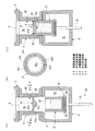
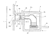
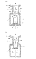
図2に示すように、前記蒸発用容器4内には、材料収納容器21を載置するとともに、当該材料収納容器21を介して材料を加熱および冷却可能な、例えば加熱用電熱線からなる加熱器28と冷却配管からなる冷却器29を有する容器載置台24が配置されている。また図3に示すように、この容器載置台23には、材料収納容器21を連通部9aに嵌入、進退させるための容器進退装置(容器進退手段)20が具備されている。すなわち、容器載置台24の下面から垂下された昇降軸26が、蒸発用容器4の底壁部に真空シール部材を介して昇降可能に貫設されており、この昇降軸26には、カップリング27を介して接続された加熱器28用の電源ケーブルと冷却器29の冷却媒体給排出用の配管がそれぞれ内装されている。そして蒸発用容器4の下方には、昇降軸26を進退駆動する電動ジャッキや油圧式シリンダなどの直線駆動装置からなる進退駆動装置31が設けられており、進退駆動装置31の出力軸が昇降軸26に連結されて容器進退装置20が構成されている。さらに昇降軸26の進退量を検出して材料収納容器21の位置を検知する進退量検出センサ30が設けられており、この進退量検出センサ30は、カップリング27に設けられた反射部材に向って昇降軸26に平行に投光して反射光を受光するように構成されている。
As shown in FIG. 2, the
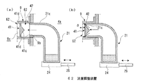
図2に示すように、前記連通部9aに、協働調整部である弁孔形成部材41が設けられ、材料収納容器21の開口部周囲に、弁孔形成部材41に接近して連通部9aにおける蒸発材料の流量を調整可能な開度調整部である開閉弁部42とが設けられ、これら弁孔形成部材41および開閉弁部42と、前記容器進退装置20とで流量調整装置(流量調整手段)40が構成されている。
As shown in FIG. 2, the
円形断面の前記連通部9aには、蒸発用容器4の入口5から少なくとも所定距離の範囲に、材料収納容器21が下方から嵌合されて略気密状態に保持可能な円形断面の気密用嵌合部9bが直線状に形成され、気密用嵌合部9bの上端部に弁孔形成部材41が配置されている。この弁孔形成部材41は、気密用嵌合部9bの上端内周の段部41aに複数本(図は4本)の支持梁41bを介して閉止ブロック41cが支持され、支持梁41b間の段部41aと閉止ブロック41cの間に円弧状の弁孔41dが形成されている。また閉止ブロック41cはその下面が、蒸気材料の流れを妨げない逆円錐形に形成されて蒸発材料を弁孔41dに導きやすくされている。一方材料収納容器21は、上面が開放された円筒形で、その上端部で開口面周囲が開閉弁部42に形成され、また材料収納容器21の高さは気密用嵌合部9bの長さよりも長く形成されている。したがって、気密用嵌合部9b内で材料収納容器21を昇降移動させることにより、開閉弁部42を弁孔41dに接近離間させてその昇降方向の隙間δにより蒸気材料の流量を調整することができる。また、入口5は材料収納容器21を挿入しやすくするために、開口面が大径になるテーパ面に形成されるので、材料収納容器21の位置ずれが修正される。
The
図1に示すように、前記予熱用容器13および取出用容器14の上壁部には、材料収納容器21の出入用の開口フランジ部13b,14bが設けられるとともに、これら開口フランジ部13b,14bには出入用ゲートバルブ(仕切弁)29,30が設けられている。
As shown in FIG. 1, opening
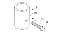
また予熱用容器13および取出用容器14の接続用通路17,18が接続された側壁部とは反対側の側壁部には、材料収納容器21を蒸発用容器4との間で移送するための移送用治具32,33が外部から操作可能に設けられている。これら各移送用治具32,33としては、図4に示すように、各容器13,14の側壁部に、水平方向で移動し得るように且つ容器13,14内の真空状態を維持し得るようにシール部材を介して棒状体35が挿通され、棒状体35の先端部に材料収納容器21の両側壁面に形成されたねじ穴(被係合部)21bに係脱自在なおねじ部(係合部)35aが形成されている。したがって、この棒状体35を回転させることにより、当該移送用治具32,33を材料収納容器21に係合および離脱することができる。36は接続部材9に内蔵された加熱用電熱線で、連通部9aを加熱して蒸発材料の付着を防止している。
In addition, the
なお、図示しないが、前記各容器3,4,12,13,14には、真空ポンプに接続された排気用配管がそれぞれ接続されており、必要に応じて、各容器3,4,12,13,14内が所定の真空度にされる。
Although not shown, each of the
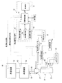
図3に示すように、前記蒸着部3aには、ガラス基板1に蒸着された膜厚を一定時間ごとに連続して測定可能な水晶振動子による膜厚測定センサ44が設けられ、蒸発部4aには容器載置台24に材料収納容器21に接触するように設けられて材料収納容器21(材料)の加熱温度を検出可能な温度センサ45が設けられている。さらに、進退量検出センサ30と膜厚測定センサ44と温度センサ45の信号に基いて、蒸着作業を自動的に行う蒸着制御装置50が設けられている。
As shown in FIG. 3, the
この蒸着制御装置50は、記憶部51、蒸着制御部52、加熱操作部53、冷却操作部54および進退操作部55を具備している。前記記憶部51は、容器進退装置20により材料収納容器21を連通部9aの気密用嵌合部9bに嵌合した嵌入位置、上限位置およびその間の位置などの略気密状態に保持できる位置データや、容器進退装置20により材料収納容器21の開閉弁部42を弁孔41dに接近させた進退位置に対応する蒸気材料の流量または開度の関係を示すデータ、材料収納容器21の進退位置(開閉弁部42の開閉)に対応した材料加熱温度データなど、試験などにより得られて材料収納容器21の進退位置に関連付けられたデータが記憶されている。また加熱操作器53は、給電装置56から容器載置台23の加熱器28に送られる電流を調整する加熱制御器57を停止、材料が蒸発する手前の温度に保持する予備加熱および材料が蒸発する温度に過熱する本加熱に応じて操作するものである。さらに冷却操作部54は、冷却水タンク58から容器載置台23の冷却器29に冷却水を供給し循環させる冷却水ポンプ61を操作するものである。さらに進退操作部55は、進退駆動装置31がたとえば油圧シリンダの場合、油圧ユニット59から進退駆動装置31に送られる圧油の給排出を制御する切換弁60を操作するものである。
The vapor
前記蒸着制御部52は、容器進退装置20により容器載置台24を介して材料収納容器21を上昇させ、気密嵌合穴部9bに材料収納容器21が所定量嵌入される(上記嵌入位置)と、これを進退量検出センサ30の検出信号により検知し、加熱操作部53により加熱制御器57を操作して自動的に加熱器28を、嵌入前から継続された予備加熱から本加熱に移行させる。
The vapor
また蒸着制御部52は、膜厚測定センサ44の検出信号に基いて、ガラス基板1の交換時期を判断する。またこのガラス基板1の交換時に、容器進退装置20により材料収納容器21を上昇させ、開閉弁部42により弁孔41dを閉じて流量調整装置20を全閉する。さらに加熱制御器53により加熱器28を停止又は予備加熱温度にすると同時に、冷却操作部54により冷却器29を起動し、材料収納容器21を材料蒸発温度以下とすることで材料の蒸発を停止し、材料収納容器21内の昇圧を防止し、蒸着用容器3への蒸発材料の流入を停止する。これは特に、熱容量の大きな材料収納容器を使った場合、材料収納容器の加熱温度を低下させただけでは直ちに材料の温度が温度が下がるものではないためである。
Further, the vapor
このような制御動作がない場合、ガラス基板1の交換時にも材料が蒸発されて蒸着部に流入しつづけ、基板交換用容器12に流出したり、流量調整装置20を全閉しても、蒸発が継続されると、材料収納容器21内に蒸発材料が充満して内部が昇圧される。蒸着を再開した時に、流量調整装置20が開放されると、材料収納容器21内に充満した高圧の蒸発材料が一気に蒸着用容器3内に流入して膜厚制御が困難になり、蒸着品質を低下せたり、蒸発材料が無駄になるおそれがある。上記制御動作により、材料のロスを防止するとともに、蒸着の再開時の蒸着膜の品質低下を防止することができる。また材料を予備加熱温度程度に下げることで、蒸発再開への移行時間が短くてすむ。
When there is no such control operation, the material is evaporated even when the
さらに蒸着制御部52は、ガラス基板1への蒸着膜厚を一定時間毎に検出して膜厚の増加量を検出し、その進退位置における同時間間隔における膜厚の増加量を記憶部51から取出して、その条件における膜厚の増加量が十分に小さい場合には、材料収納容器21内の材料が減少した材料収納容器21の交換時期であると判断して材料収納容器21の交換を決定する。
Further, the vapor
次に上記構成の蒸着装置における蒸着作業を説明する。
上記構成において、容器載置台24に載置された材料収納容器21は、加熱器28により予備過熱された状態で、進退駆動装置31が進展されて容器載置台24が上昇され、材料収納容器21が連通部9aの気密嵌合穴部9bに嵌入される。この時、進退量検出センサ30により材料収納容器21の進退位置が検出されており、蒸着制御部50では、記憶部51のデータを参照して、材料収納容器21が気密嵌合穴部9bに嵌入されて気密状態に保持される位置になったと判断すると、加熱操作部53を介して加熱制御器57を操作し、加熱器28により材料収納容器21を本加熱に切替え材料を蒸発させる。
Next, the vapor deposition operation in the vapor deposition apparatus having the above configuration will be described.
In the above-described configuration, the
そして、流量調整装置40が全開である位置で進退駆動装置31を停止させ、加熱蒸発された蒸発材料を弁穴41dを介して連通部9aから蒸着部3aに導入させ、保持具2に保持されたガラス基板1の表面(下面)に蒸発材料を蒸着させる。
Then, the forward /
膜厚測定センサ44によりガラス基板1の表面の膜厚が所定値に達したと判断すると、ガラス基板1の交換を行う。蒸着制御部50では、まず加熱操作部53により加熱制御器57を操作して加熱器28による加熱を停止又は予備加熱に切替えると同時に、記憶部51のデータに基いて進退駆動装置31を進展させて材料収納容器21の開閉弁部42により弁穴41dを閉止させて流量調整装置40を全閉位置(上限位置)とし、冷却操作部54により冷却水ポンプ61を起動して冷却水を容器載置台23の冷却器29に送り、材料収納容器21の材料を強制的に冷却する。この冷却は、材料収納容器(材料)が蒸発温度を下回ったら停止する。
When the film
出入口ゲートバルブ10を開け、接続用通路11を介して蒸発用容器4内と同程度の真空状態とした基板交換用容器12に蒸着したガラス基板1を搬出するとともに、次のガラス基板1を搬入する。
The entrance /
次のガラス基板1が保持具2に保持されると、蒸着制御部50では加熱操作部53により加熱器28をオン(停止→本加熱、または予備加熱→本加熱)し、加熱を再開する。次いで進退操作部55により切換弁60を操作して進退駆動装置31を収縮させ、材料収納容器21を下降させて開閉弁部42を弁穴41dから離間させ流量調整装置40を全開する。これにより、次のガラス基板1の蒸着作業が開始される。
When the
何枚ものガラス基板1への蒸着が進むにつれて、さらに材料収納容器21を交換して材料を補充する必要があると判断された場合には、予熱用容器13で次の材料の予備加熱が行われる。
As it is determined that it is necessary to replace the
そして、膜厚測定センサ44によりガラス基板1の表面の膜厚の増加率が所定以下になると、蒸着制御部50では予熱用容器13内の材料が少なくなったと判断して、加熱操作部53により加熱制御器57を介して加熱器28をオフするとともに、冷却操作部54により冷却水ポンプ61を起動して冷却器29による冷却を開始する。次いで、進退操作部55により切換弁60を操作して進退駆動装置31を収縮させ、材料収納容器21を気密嵌合穴部9bから蒸発部4aに抜き出す。
When the rate of increase of the film thickness on the surface of the
そして、棒状体35により使用済みの材料収納容器21を接続用通路18から搬出用ゲートバルブ16を介して取出用容器14に送り出し、さらに予熱用容器13から新たな材料収納容器21を接続用通路17から搬入用ゲートバルブ15を介して蒸発用容器4に搬入する。搬入、搬出作業がそれぞれ終ると、それぞれのゲートバルブ16,15も閉じられる。
Then, the used
上記実施の形態によれば、進退駆動装置31により材料収納容器21を連通部9aの気密嵌合穴部9bに嵌入することにより、材料収納容器21と蒸発部4aの空間とが略気密状態に分離されるので、材料収納容器21内から蒸発された蒸発材料が連通部9aから直接蒸着部3aに導入され、蒸発材料が蒸発部4a内に充満されることがないため、材料の効率的な利用に繋がる。またこれにより、ガラス基板1の交換時や材料収納容器21の交換時における材料ロスを低減することができる。また材料収納容器21が連通部9aに嵌合される連続動作で、流量調整装置40を操作することができて連通部9aにおける蒸発材料の流量を調整することができる。したがって、進退駆動装置31により材料収納容器21の気密性の確保と、蒸発材料の流量調整とを兼用して行うことができ、装置を簡易化できて設備コストの低減に寄与できる。
According to the embodiment described above, the
また、蒸発部4aと蒸着部3aをそれぞれ独立した蒸発用容器3と蒸着用容器3に設けることで、空間容量を削減することができて、ガラス基板1や材料収納容器21の交換時における蒸発材料のロスを低減することができる。
Further, by providing the evaporating
[実施の形態2]
図5は、本発明に係る実施の形態2の蒸着装置でサイドデポジションタイプであり、90°転向された流量調整装置62を設けたものである。これは材料収納容器21を横方向(図では水平方向)に進退させるもので、材料収納容器21には、上部が側方に90°で折れ曲り、水平方向の連通部9aの気密嵌合穴部9bに略気密状態でかつ出退自在に嵌合される気密用水平嵌合部21cが形成され、気密用水平嵌合部21cの開口部周囲に、開閉弁部41が設けられている。上記実施の形態1の変形例によれば、実施の形態1と同様の作用効果を奏することができる。
[Embodiment 2]
FIG. 5 is a side deposition type vapor deposition apparatus according to the second embodiment of the present invention, which is provided with a flow
なお、実施の形態1および2では、流量調整装置40,62を全開と全閉との二段階で流量調整したが、複数段階または無段階で流量調整することもできる。
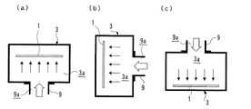
また、図6に示すように、蒸着方向として、(a)のアッパーデポジションタイプの蒸着部3aを示したが、(b)のサイドデポジションの蒸着部3aや(c)のダウンデポジションタイプの蒸着部3aであってもよい。
In the first and second embodiments, the flow
Moreover, as shown in FIG. 6, although the upper deposition type
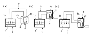
さらに、上記実施の形態では連通部9aの形状を直線状に形成したが、これに限るものではなく、図7(a)〜(c)に示すように、連通部9aのうち、気密嵌合部9bまでは直線状にし、それ以外を折り曲げてもよく、ダウンデポジションタイプの蒸着用容器3に接続された接続部材9を折れ曲り状に形成することもできる。
Furthermore, in the said embodiment, although the shape of the
[実施の形態3]
流量調整装置の異なる蒸着装置の実施の形態3を、図8を参照して説明する。なお、実施の形態1と同一部材には同一符号を付して説明を省略する。
[Embodiment 3]
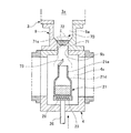
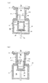
この蒸着装置は、上下方向に形成された連通部9aを有し、前記連通部9aの中間部に形成された弁孔部(協働調整部)71と、前記弁孔部71に昇降自在に配置されて自重により弁孔部71を閉止する第1弁体(協働調整部)72と、材料収納容器21の上部に突出されて前記第1弁体72を押し上げ弁孔部71を開放可能な第1弁体作動部(開度調整部)73とにより流量調整装置70が構成されている。
This vapor deposition apparatus has a communicating
前記弁穴部71は、上位大径部から下位小径部に至るテーパ状着座面71aに形成され、またこの着座面71aに、逆円錐台形の第1弁体72が押上自在に配置されている。第1弁体72の昇降ガイド部材を設けてもよい。前記第1弁体作動部73は、先端部が第1弁体72下面中央の載頭凹部に嵌って押上可能なアーム状に形成されている。
The
前記材料収納容器21は、縮径部21dを介して上部に気密用垂直嵌合部21eが形成され、この気密用垂直嵌合部21eは連通部9aの気密嵌合穴部9bに嵌脱自在で、嵌合状態で材料収納容器21内と蒸発部4aとが略気密状態となるように構成されている。
The
上記構成において、容器載置台24に載置された材料収納容器21は、加熱器28により予備加熱された状態で、進退駆動装置31が進展されて上昇され、気密用垂直嵌合部21eが気密嵌合穴部9bに嵌入される。この時、進退量検出センサ30により気密嵌合穴部9bに嵌合された材料収納容器21が気密状態に保持される位置となると、加熱器28が予備加熱から本加熱に切替えられる。
In the above configuration, the
さらに進退駆動装置31により材料収納容器21を上昇させることで、第1弁体作動部73により第1弁体72を押し上げて弁穴部71を開放する位置で停止させ、流量調整装置70を全開とする。これにより、加熱蒸発された蒸発材料を弁穴部71を介して連通部9aから蒸着部3aに導入し、保持具2に保持されたガラス基板1の表面(下面)に蒸発材料を蒸着させる。
Further, the
ガラス基板の交換時には進退駆動装置31により材料収納容器21を下降させて第1弁体72を弁穴部71の着座面71aに着地させ、弁穴部71を全閉する。その後の動作は、第1の実施の形態と同様に行う。
When the glass substrate is replaced, the
上記実施の形態3によれば、実施の形態1と同様の効果を奏することができる。なお、材料収納容器21の縮径部21dが入口5に接触して進退駆動装置31の進展上限を規定している。
According to the third embodiment, the same effect as in the first embodiment can be obtained. The reduced
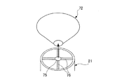
図9は第1弁体作動部の変形例を示し、第1弁体72を押上可能な第1弁体作動部75を、複数のブリッジ76を介して材料収納容器21の開口部に配置したものである。
[実施の形態4]
実施の形態3の流量調整装置70を横置きにしたサイドデポジションタイプの蒸着装置の実施の形態4を、図10に基いて説明する。なお、実施の形態3と同一部材には同一符号を付して説明を省略する。
FIG. 9 shows a modified example of the first valve body operating portion, and the first valve
[Embodiment 4]
A fourth embodiment of the side deposition type vapor deposition apparatus in which the flow
この流量調整装置80は、水平方向に形成された連通部9aの気密嵌合穴部9bの出口側に形成された弁孔部(協働調整部)81と、前記弁孔部81に当接離間自在に配置されてコイルばね(付勢部材)84により弁孔部81を閉止する第2弁体(協働調整部)82と、材料収納容器21の気密用水平嵌合部21cから突出されて前記第2弁体82を押し出して弁孔部81を開放可能な第2弁体作動部(開度調整部)83とにより流量調整装置80が構成されている。
The flow
前記弁穴部81は、出口側大径部から入口側小径部に至るテーパ状着座面81aが形成されている。84aは、連通部9aの出口側に設けられたコイルばね84の支持部材である。進退駆動装置31による材料収納容器21の進退方向が水平方向に変更され、気密用水平嵌合部21cと気密用嵌合孔部9bとが嵌合させれる他は、実施の形態3と同様な動作で蒸発が実施される。なお、ここで連通部9aを水平方向としたが、傾斜角度を持つ横方向であってもよい。
The
上記実施の形態4の変形例によれば、実施の形態1と同様の効果を奏することができる。
[実施の形態5]
他の流量調整装置90を有する蒸着装置の実施の形態5を、図11に基いて説明する。なお、実施の形態1と同一部材には同一符号を付して説明を省略する。
According to the modification of the fourth embodiment, the same effects as those of the first embodiment can be obtained.
[Embodiment 5]
接続部材9は、上端部および下端部にフランジを有する外筒部91aと、上端部フランジから外筒部91a内に垂下されて連通部9aを形成する気密用筒部91bとを具備し、前記気密用筒部91bに、材料収納容器21の上部内面に形成された気密用垂直嵌合部21eが下方から外嵌されることにより、材料収納容器21内と蒸発部4aとを略気密状態に保持できるように構成されている。ここで気密用垂直嵌合部21eの長さは第3弁体92よりも長く形成されている。
The connecting
前記気密用筒部91bの下端部には、基端部が連通部9aの周方向(接線方向)の軸心周りに揺動自在に取り付けられた複数(図では4枚)の花弁状の第3弁体92(協働調整部)が設けられている。これら第3弁体92は、通常の非作用時に、材料の持つ弾性(またはばねなどの付勢部材)により連通部9aを開放する位置に保持されている。またこの開放状態で第3弁体92に外嵌して閉動可能な第3弁体作動部(開度調整部)93が材料収納容器21の気密用垂直嵌合部21eの下部周囲に設けられている。第3弁体作動部93は、気密用垂直嵌合部21eから下部ほど縮径されたテーパ面に形成されている。したがって、第3弁体作動部93が第3弁体92の先端部に当接して内側に揺動させ、連通部9aを略閉止状態にすることができる。
A plurality of (four in the figure) petal-shaped first base ends are attached to the lower end of the airtight
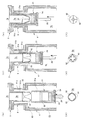
上記構成において、図11(a)(b)に示すように、容器載置台24に載置された材料収納容器21は、加熱器28により予備加熱された状態で、進退駆動装置31が進展されて上昇され、気密用垂直嵌合部21eが第3弁体92および気密用筒部91bに外嵌される。そして、進退量検出センサ30により材料収納容器21が気密状態に保持される位置になると、加熱器28が予備加熱から本加熱に切替えられる。
In the above configuration, as shown in FIGS. 11A and 11B, the
さらに進退駆動装置31により材料収納容器21を上昇させて第3弁体作動部93が第3弁体92に接触する手前の全開位置で停止される。これにより、流量調整装置90が全開状態で蒸着作業が開始され、蒸発材料を連通部9aから蒸着部3aに導入して、保持具2に保持されたガラス基板1の表面(下面)に蒸発材料を蒸着される。
Furthermore, the
ガラス基板1の交換時には、図11(c)(d)に示すように、進退駆動装置31により材料収納容器21を上昇させて第3弁体作動部93により第3弁体93を閉動させ、図11(e)(f)に示すように、連通部9aを閉止する。その後の動作は、第1の実施の形態と同様に行う。
When replacing the
上記第5の実施の形態によれば、第1の実施の形態と同様の作用効果を奏することができる。なお、図11(b)(d)(f)は、蒸着部3aから見た開度状態を示している。
[実施の形態6]
実施の形態6は、実施の形態5の変形例で図12に基いて説明する。なお、実施の形態5と同一部材には同一符号を付して説明を省略する。
According to the fifth embodiment, the same operational effects as those of the first embodiment can be obtained. In addition, FIG.11 (b) (d) (f) has shown the opening degree state seen from the
[Embodiment 6]
The sixth embodiment is a modification of the fifth embodiment and will be described with reference to FIG. Note that the same members as those in the fifth embodiment are denoted by the same reference numerals and description thereof is omitted.
材料収納容器21の開口部周囲には、基端部が周方向(接線方向)の軸心周りに揺動自在に取り付けられた複数(図では4枚)の花弁状の第4弁体(開度調整部)96が設けられており、第4弁体96は通常の非作用時に、材料の持つ弾性(またはばねなどの付勢部材)により材料収納容器21の外周面の上方に連続する位置に保持されて開口部が開放されている。
Around the opening of the
また連通部9aの気密用筒部9bの上部には、上方ほど縮径されて第4弁体96を開閉可能なテーパ状の第4弁体作動部(協働調整部)97が設けられて流量調整装置95が構成されている。
In addition, a tapered fourth valve body actuating portion (cooperation adjusting portion) 97 that is reduced in diameter toward the upper side and can open and close the
したがって、気密用筒部9b内で材料収納容器21が上昇されて第4弁体96の先端部または外側面が第4弁体作動部97に当接されることで、第4弁体96が閉動されて閉じられ、その進退位置により材料収納容器21の開口部から放出される蒸発材料の流量を調整することができる。
Therefore, the
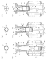
上記構成において、図12(a)(b)に示すように、容器載置台23に載置された材料収納容器21は、加熱器28により予備加熱された状態で、進退駆動装置31が進展されて上昇され、材料収納容器21の第4弁体96および気密用垂直嵌合部21eが連通部9aの気密嵌合穴部9bに下方から嵌入される。ここで気密用筒部9bの長さが第4弁体96よりも長く形成されており、進退量検出センサ30により材料収納容器21が気密状態に保持される位置になると、加熱器28が予備加熱から本加熱に切替えられる。
In the above configuration, as shown in FIGS. 12A and 12B, the
さらに進退駆動装置31により材料収納容器21が上昇されて第4弁体96が第4弁体作動部97に接触する手前の全開位置で停止される。これにより、流量調整装置95が全開状態で蒸着作業が開始され、連通部9aから蒸発材料が蒸着部3aに導入されて、保持具2に保持されたガラス基板1の表面(下面)に蒸発材料が蒸着される。
Furthermore, the
ガラス基板1の交換時には、図12(c)(d)に示すように、進退駆動装置31により材料収納容器21を上昇させ、第4弁体作動部97を第4弁体96の先端部から外側面に当接させて閉動させ、図12(e)(f)に示すように、上昇限の全閉位置で停止される。さらにその後の動作は、第1の実施の形態と同様に行う。
When replacing the
上記第6の実施の形態によれば、第1の実施の形態と同様の作用効果を奏することができる。
[実施の形態7]
他の流量調整装置を有する蒸着装置の実施の形態7を、図13に基いて説明す。なお、実施の形態1と同一部材には同一符号を付して説明を省略する。
According to the sixth embodiment, the same operational effects as those of the first embodiment can be obtained.
[Embodiment 7]
Embodiment 7 of the vapor deposition apparatus which has another flow volume adjustment apparatus is demonstrated based on FIG. The same members as those in the first embodiment are denoted by the same reference numerals and description thereof is omitted.
この流量調整装置100は、連通部9aの気密嵌合穴部9bの上部に、連通穴9aの軸心に直交する支軸101aに回動自在に配置されたバタフライ弁形の第5弁体(協働調整部)101と、材料収納容器21の開口縁部から上方に突出されて第5弁体101を開動可能な板状の第5弁体作動部(開度調整部)102とで構成されている。前記気密嵌合穴部9bの上部の対向面には、第5弁体101の一方の回動を規制する受け側と押え側の係止段部103が形成され、第5弁体101は前記受け側の重量を押え側より大きくして、非作用状態(通常時)に連通部9aを閉止するように構成されている。もちろん、第5弁体101を閉止側に回動付勢するコイルばねなどの付勢部材を支軸101aに介装してもよい。
The flow
上記構成において、容器載置台24に載置された材料収納容器21は、図13(a)に示すように、加熱器28により予備加熱された状態で、進退駆動装置31が進展されて上昇され、材料収納容器21が連通部9aの気密嵌合穴部9bに下方から嵌入される。そして、進退量検出センサ30により材料収納容器21が気密状態に保持される位置になると、加熱器28が予備加熱から本加熱に切替えられる。
In the above configuration, the
さらに進退駆動装置31により材料収納容器21が上昇されて第5弁体作動部102により第5弁体101の遊端部を押し上げて開放させ、全開位置で停止される。これにより、流量調整装置100が全開状態で蒸着作業が開始され、蒸発材料が連通部9aから蒸着部3aに導入されて、保持具2に保持されたガラス基板1の表面(下面)に蒸発材料が蒸着される。
Further, the
ガラス基板1の交換時には、進退駆動装置31により材料収納容器21を下降させて第5弁体作動部102が第5弁体101から離間する位置で停止させ、第5弁体101を係止段部103まで回動させて流量調整装置100を閉止する。さらにその後の動作は、第1の実施の形態と同様に行う。なお、ここでも気密嵌合孔部9bの長さが第5弁体作動部102よりも長いものとする。
When the
上記第7の実施の形態によれば、第1の実施の形態と同様の作用効果を奏することができる。
[実施の形態8]
実施の形態7の弁体と弁体作動部とを逆に配設した実施の形態8を、図14に基いて説明する。なお、実施の形態1と同一部材には同一符号を付して説明を省略する。
According to the said 7th Embodiment, there can exist an effect similar to 1st Embodiment.
[Embodiment 8]
An eighth embodiment in which the valve body and the valve body actuating portion of the seventh embodiment are disposed in reverse will be described with reference to FIG. The same members as those in the first embodiment are denoted by the same reference numerals and description thereof is omitted.
すなわち、流量調整装置110は、材料収納容器21の開口部に容器軸心に直交する支軸111aに回動自在に配置されたバタフライ弁形の第6弁体111と、連通部9aの気密嵌合穴部9bの上部に、下方に向って突出されて第6弁体111を開閉可能な板状の第6弁体作動部112とで構成されている。前記材料収納容器21の開口部には、第6弁体111の一方の回動を規制する係止部113が形成され、第6弁体111は前係止部113の反対側の重量をより大きくして、非作用状態(通常時)で開口部を閉止するように構成されている。もちろん、第6弁体111を閉止側に回動付勢するコイルばねなどの付勢部材を支軸111aに介装してもよい。
That is, the flow
上記構成において、図14(a)に示すように、容器載置台23に載置された材料収納容器21は、加熱器28により予備加熱された状態で、進退駆動装置31が進展されて上昇され、材料収納容器21が連通部9aの気密嵌合穴部9bに下方から嵌入される。そして、進退量検出センサ30により材料収納容器21が気密状態に保持される位置になると、加熱器28が予備加熱から本加熱に切替えられる。
In the above configuration, as shown in FIG. 14A, the
さらに進退駆動装置31により材料収納容器21がさらに上昇され、図14(b)に示すように、第6弁体作動部112により第6弁体111の遊端側を押し下げて、開口部を全開する位置で停止される。これにより、流量調整装置110が全開状態で蒸着作業が開始され、連通部9aから蒸発材料が蒸着部3aに導入されて、保持具2に保持されたガラス基板1の表面(下面)に蒸発材料が蒸着される。
Further, the
ガラス基板1の交換時には、進退駆動装置31により材料収納容器21を下降させて第5弁体作動部112が第5弁体111から離間する位置で停止させ、第6弁体111を係止部113に当接する位置まで回動させて材料収納容器21の開口部を閉止する。さらにその後の動作は、第1の実施の形態と同様に行う。ここで、第6弁体作動部112の先端は、入口5よりも上方に位置している。
When the
上記第7の実施の形態によれば、第1の実施の形態と同様の作用効果を奏することができる。
なお、上記蒸着装置では、真空雰囲気で蒸着を実施したが、蒸発材料により不活性ガス雰囲気で蒸着を行うこともできる。
According to the said 7th Embodiment, there can exist an effect similar to 1st Embodiment.
In the above-described vapor deposition apparatus, vapor deposition is performed in a vacuum atmosphere, but vapor deposition can also be performed in an inert gas atmosphere using an evaporation material.
1 ガラス基板(被蒸着部材)
3 蒸着用容器
3a 蒸着部
4 蒸発用容器
4a 蒸発部
9 接続部材
9a 連通部
9b 気密嵌合部
20 容器進退装置
21 材料収納容器
21b ねじ穴
21c 気密用水平嵌合部
21e 気密用垂直嵌合部
24 容器載置台
26 昇降軸
27 カップリング
28 加熱器
29 冷却器
30 進退量検出センサ
31 進退駆動装置
40 流量調整装置
41 弁孔形成部材
41a 段部
41b 支持梁
41c 閉止部目
41d 弁孔
42 開閉弁部
44 膜厚測定センサ
45 温度センサ
50 蒸着制御部
51 記憶部
52 蒸着制御部
53 加熱操作部
54 冷却操作部
55 進退操作部
71 弁孔部
71a 着座面
72 第1弁体
73 第1弁体作動部
80 流量調整装置
81 弁孔部
81a 着座面
82 第2弁体
83 第2弁体作動部
90 流量調整装置
92 第3弁体
93 第3弁体作動部
95 流量調整装置
96 第4弁体
97 第4弁体作動部材
100 流量調整装置
101 第5弁体
102 第5弁体作動部
110 流量調整装置
111 第5弁体
112 第5弁体作動部
1 Glass substrate (deposition material)
DESCRIPTION OF
Claims (13)
前記連通部に設けられた協働調整部と、前記材料収納容器を連通部に嵌合するとともに前記協働調整部に対して接近離間方向に往復移動させる容器進退手段と、前記材料収納容器に設けられて協働調整部に接近または当接し連通部における蒸発材料の流量を調整可能な開度調整部とを備えた流量調整手段を設け、
前記容器進退手段により材料収納容器を連通部に嵌合されることにより、材料収納容器と連通部とが略気密状態に接続される
ことを特徴とする蒸着装置。 A vapor deposition apparatus comprising: a vapor deposition unit that heats a material storage container to evaporate a material; a vapor deposition unit that adheres the vaporized material to a vapor deposition member; and a communication unit that guides the vaporized material from the vaporization unit to the vapor deposition unit. And
A coordinating adjustment portion provided in the communication portion, a container advancing / retreating means for fitting the material storage container to the communication portion and reciprocating in the approaching / separating direction with respect to the cooperating adjustment portion, and the material storage container. Provided with a flow rate adjusting means provided with an opening degree adjusting unit that can be adjusted to approach or abut the collaborative adjusting unit and adjust the flow rate of the evaporation material in the communicating unit;
The material storage container and the communication part are connected in a substantially airtight state by fitting the material storage container to the communication part by the container advance / retreat means.
前記蒸発用容器と蒸着用容器とを接続する接続部材に、少なくとも前記蒸発用容器側に容器進退手段の進退方向に沿いかつ材料収納容器と連通部とが略気密状態に接続される部位を有する連通部を形成した
ことを特徴とする請求項1記載の蒸着装置。 An evaporation part is provided in the evaporation container, and an evaporation part is independently provided in the evaporation container,
The connecting member for connecting the evaporation container and the evaporation container has at least a portion on the evaporation container side along the advancing / retreating direction of the container advancing / retreating unit and the material storage container and the communication portion being connected in a substantially airtight state. The vapor deposition apparatus according to claim 1, wherein a communication portion is formed.
開度調整部は、前記弁孔に接近離間して流路断面積を縮小調整可能な開閉弁部により構成された
ことを特徴とする請求項1または2記載の蒸着装置。 The coordinating adjustment part is configured by a valve hole forming member that forms a valve hole in the communication part,
The vapor deposition apparatus according to claim 1, wherein the opening degree adjustment unit is configured by an on-off valve unit that can adjust the flow path cross-sectional area to be close to and away from the valve hole.
協働調整部は、前記連通部に形成された弁孔部と、前記弁孔部に昇降自在に配置されて自重により閉止する第1弁体とで構成され、
開度調整部は、前記第1弁体を押し上げて弁孔部を開放可能な第1弁体作動部により構成された
ことを特徴とする請求項1または2記載の蒸着装置。 It has a communication part formed in the vertical direction,
The coordinating adjustment unit is composed of a valve hole portion formed in the communication portion, and a first valve body that is disposed so as to be movable up and down in the valve hole portion and is closed by its own weight,
The vapor deposition apparatus according to claim 1 or 2, wherein the opening degree adjusting unit is configured by a first valve body operating unit that can push up the first valve body to open the valve hole.
協働調整部は、前記連通部に形成された弁孔部と、付勢部材により弁孔部に押し付けられて弁孔部を閉止する第2弁体とを有し、
開度調整部は、前記第2弁体を付勢部材に抗して押し戻し弁孔部を開放可能な第2弁体作動部により構成された
ことを特徴とする請求項1または2記載の蒸着装置。 Having a communicating portion formed in the lateral direction;
The cooperative adjustment portion has a valve hole portion formed in the communication portion, and a second valve body that is pressed against the valve hole portion by the urging member to close the valve hole portion,
3. The vapor deposition according to claim 1, wherein the opening degree adjusting unit is configured by a second valve body operating unit capable of opening the return valve hole against the biasing member against the second valve body. apparatus.
開度調整部は、前記第3弁体を揺動して連通部を開度調整可能な第3弁体作動部により構成された
ことを特徴とする請求項1または2記載の蒸着装置。 The coordinating adjustment portion is configured by a plurality of third valve bodies that are provided in the communication portion so as to be swingable around the axial center in the circumferential direction and open the communication portion when not in operation.
The vapor deposition apparatus according to claim 1, wherein the opening degree adjusting unit is configured by a third valve body operating unit that can swing the third valve body and adjust the opening degree of the communication part.
協働調整部は、第4弁体を揺動して材料収納容器の開口部の開度調整可能な第4弁体作動部により構成された
ことを特徴とする請求項1または2記載の蒸着装置。 The opening adjustment unit is configured by a plurality of fourth valve bodies that are swingably provided in the opening of the material storage container and open the opening when not in operation,
The vapor deposition according to claim 1 or 2, wherein the cooperative adjustment unit is configured by a fourth valve body operating unit that swings the fourth valve body and can adjust an opening degree of the opening of the material storage container. apparatus.
開度調整部は、第5弁体を開動して連通部を開度調整可能な第5弁体開動部により構成された
ことを特徴とする請求項1または2記載の蒸着装置。 The coordinating adjustment portion is configured by a fifth valve body that is rotatably arranged around an axis orthogonal to the communication portion and that makes the communication portion substantially closed when inactive.
The vapor deposition apparatus according to claim 1, wherein the opening degree adjusting unit is configured by a fifth valve body opening unit that can open the fifth valve body and adjust the opening degree of the communication unit.
協働調整部は、第6弁体を開動して容器の開口部を開度調整可能な第6弁体作動部で構成された
ことを特徴とする請求項1または2記載の蒸着装置。 The opening adjustment unit is configured by a sixth valve body that is rotatably arranged around an axis orthogonal to the opening of the material storage container and that makes the opening substantially closed when inactive.
The vapor deposition apparatus according to claim 1, wherein the coordinating adjustment unit is configured by a sixth valve body actuating unit capable of opening the sixth valve body to adjust an opening of the container.
容器進退手段による材料収納容器の移動量を検出する進退量検出手段を設け、
前記進退量検出手段の検出信号に対応して材料加熱手段を制御する蒸着制御部を有する蒸着制御装置を設けた
ことを特徴とする請求項1乃至9の何れかに記載の蒸着装置。 A material heating means for heating the vapor deposition material in the material storage container is provided,
Providing advance / retreat amount detection means for detecting the amount of movement of the material storage container by the container advance / retreat means,
The vapor deposition apparatus according to claim 1, further comprising: a vapor deposition control device having a vapor deposition control unit that controls the material heating unit in response to a detection signal of the advance / retreat amount detection unit.
蒸着制御部は、前記付着量検出手段の検出信号に対応して前記容器進退手段を操作するように構成された
ことを特徴とする請求項10記載の蒸着装置。 A deposition amount detecting means for detecting the deposition amount of the evaporation material on the deposition target member is provided in the deposition unit,
The vapor deposition apparatus according to claim 10, wherein the vapor deposition control unit is configured to operate the container advance / retreat unit in response to a detection signal of the adhesion amount detection unit.
蒸着制御部は、進退量検出手段の検出信号により前記記憶部のデータに基いて材料加熱手段を制御するように構成された
ことを特徴とする請求項10または11記載の蒸着装置。 The vapor deposition control device stores the position where the material storage container is connected to the communication portion in an airtight state, the flow rate of the evaporation material in the communication portion, and the material heating temperature in accordance with the amount of movement of the material storage container. Comprising
The vapor deposition apparatus according to claim 10 or 11, wherein the vapor deposition control unit is configured to control the material heating unit based on data in the storage unit based on a detection signal of the advance / retreat amount detection unit.
蒸着制御部は、進退量検出手段の検出信号により記憶部のデータに基いて材料冷却手段を制御するように構成された
ことを特徴とする請求項12記載の蒸着装置。 A material cooling means for cooling the vapor deposition material in the material container is provided,
The vapor deposition apparatus according to claim 12, wherein the vapor deposition control unit is configured to control the material cooling unit based on data in the storage unit based on a detection signal of the advance / retreat amount detection unit.
Priority Applications (1)
| Application Number | Priority Date | Filing Date | Title |
|---|---|---|---|
| JP2004118450A JP4462989B2 (en) | 2004-04-14 | 2004-04-14 | Vapor deposition equipment |
Applications Claiming Priority (1)
| Application Number | Priority Date | Filing Date | Title |
|---|---|---|---|
| JP2004118450A JP4462989B2 (en) | 2004-04-14 | 2004-04-14 | Vapor deposition equipment |
Publications (2)
| Publication Number | Publication Date |
|---|---|
| JP2005298926A true JP2005298926A (en) | 2005-10-27 |
| JP4462989B2 JP4462989B2 (en) | 2010-05-12 |
Family
ID=35330835
Family Applications (1)
| Application Number | Title | Priority Date | Filing Date |
|---|---|---|---|
| JP2004118450A Expired - Fee Related JP4462989B2 (en) | 2004-04-14 | 2004-04-14 | Vapor deposition equipment |
Country Status (1)
| Country | Link |
|---|---|
| JP (1) | JP4462989B2 (en) |
Cited By (14)
| Publication number | Priority date | Publication date | Assignee | Title |
|---|---|---|---|---|
| JP2007126303A (en) * | 2005-11-01 | 2007-05-24 | Nippon Biitec:Kk | Molecular beam source for thin film deposition and its molecular dose control method |
| JP2008156724A (en) * | 2006-12-25 | 2008-07-10 | Matsushita Electric Works Ltd | Vacuum deposition system |
| JP2008156726A (en) * | 2006-12-25 | 2008-07-10 | Matsushita Electric Works Ltd | Vacuum deposition system |
| JP2008169456A (en) * | 2007-01-15 | 2008-07-24 | Matsushita Electric Works Ltd | Vacuum deposition system |
| JP2009515052A (en) * | 2005-11-07 | 2009-04-09 | セメス カンパニー リミテッド | Organic substance deposition apparatus and method, and substrate processing system including the same |
| JP2009185325A (en) * | 2008-02-05 | 2009-08-20 | Panasonic Electric Works Co Ltd | Vapor deposition equipment |
| JP2010031324A (en) * | 2008-07-29 | 2010-02-12 | Tokyo Electron Ltd | Vapor deposition source unit, vapor deposition method, controller for vapor deposition source unit and film deposition system |
| WO2012030792A1 (en) * | 2010-08-30 | 2012-03-08 | First Solar, Inc. | Vapor deposition system |
| JP2012508815A (en) * | 2008-11-17 | 2012-04-12 | エスエヌユー プレシジョン カンパニー,リミテッド | Vapor deposition material supply apparatus and substrate processing apparatus provided with the same |
| JP2012107287A (en) * | 2010-11-17 | 2012-06-07 | Ulvac Japan Ltd | Thin film deposition apparatus |
| KR101450174B1 (en) | 2006-04-21 | 2014-10-14 | 아익스트론 에스이 | Cvd reactor having a process chamber lid which can be lowered |
| CN110117770A (en) * | 2018-02-06 | 2019-08-13 | 三星显示有限公司 | Organic deposition device and the organic deposition method for utilizing this |
| CN112663000A (en) * | 2020-12-07 | 2021-04-16 | 肇庆市科润真空设备有限公司 | Different-direction evaporation device and method for vacuum coating equipment |
| JP2023140215A (en) * | 2022-03-22 | 2023-10-04 | 株式会社アルバック | Deposition source for vacuum evaporation equipment |
Families Citing this family (1)
| Publication number | Priority date | Publication date | Assignee | Title |
|---|---|---|---|---|
| CN106906445B (en) * | 2017-03-29 | 2019-02-12 | 武汉华星光电技术有限公司 | A kind of evaporation source |
-
2004
- 2004-04-14 JP JP2004118450A patent/JP4462989B2/en not_active Expired - Fee Related
Cited By (17)
| Publication number | Priority date | Publication date | Assignee | Title |
|---|---|---|---|---|
| JP2007126303A (en) * | 2005-11-01 | 2007-05-24 | Nippon Biitec:Kk | Molecular beam source for thin film deposition and its molecular dose control method |
| KR101284394B1 (en) * | 2005-11-01 | 2013-07-09 | 쵸슈 산교 가부시키가이샤 | A molecular beam source for use of thin-film accumulation and a method for controlling volume of molecular beam |
| TWI398557B (en) * | 2005-11-01 | 2013-06-11 | 長州產業股份有限公司 | Molecular line source for film deposition and molecular line amount control method thereof |
| JP2009515052A (en) * | 2005-11-07 | 2009-04-09 | セメス カンパニー リミテッド | Organic substance deposition apparatus and method, and substrate processing system including the same |
| KR101450174B1 (en) | 2006-04-21 | 2014-10-14 | 아익스트론 에스이 | Cvd reactor having a process chamber lid which can be lowered |
| JP2008156726A (en) * | 2006-12-25 | 2008-07-10 | Matsushita Electric Works Ltd | Vacuum deposition system |
| JP2008156724A (en) * | 2006-12-25 | 2008-07-10 | Matsushita Electric Works Ltd | Vacuum deposition system |
| JP2008169456A (en) * | 2007-01-15 | 2008-07-24 | Matsushita Electric Works Ltd | Vacuum deposition system |
| JP2009185325A (en) * | 2008-02-05 | 2009-08-20 | Panasonic Electric Works Co Ltd | Vapor deposition equipment |
| JP2010031324A (en) * | 2008-07-29 | 2010-02-12 | Tokyo Electron Ltd | Vapor deposition source unit, vapor deposition method, controller for vapor deposition source unit and film deposition system |
| JP2012508815A (en) * | 2008-11-17 | 2012-04-12 | エスエヌユー プレシジョン カンパニー,リミテッド | Vapor deposition material supply apparatus and substrate processing apparatus provided with the same |
| WO2012030792A1 (en) * | 2010-08-30 | 2012-03-08 | First Solar, Inc. | Vapor deposition system |
| JP2012107287A (en) * | 2010-11-17 | 2012-06-07 | Ulvac Japan Ltd | Thin film deposition apparatus |
| CN110117770A (en) * | 2018-02-06 | 2019-08-13 | 三星显示有限公司 | Organic deposition device and the organic deposition method for utilizing this |
| CN112663000A (en) * | 2020-12-07 | 2021-04-16 | 肇庆市科润真空设备有限公司 | Different-direction evaporation device and method for vacuum coating equipment |
| JP2023140215A (en) * | 2022-03-22 | 2023-10-04 | 株式会社アルバック | Deposition source for vacuum evaporation equipment |
| JP7856456B2 (en) | 2022-03-22 | 2026-05-11 | 株式会社アルバック | Evaporation source for vacuum deposition apparatus |
Also Published As
| Publication number | Publication date |
|---|---|
| JP4462989B2 (en) | 2010-05-12 |
Similar Documents
| Publication | Publication Date | Title |
|---|---|---|
| JP4462989B2 (en) | Vapor deposition equipment | |
| TWI336735B (en) | Apparatus for treating thin film and method of treating thin film | |
| JP5372243B2 (en) | Raw material supply unit, thin film deposition apparatus and thin film deposition method | |
| KR100926437B1 (en) | Evaporation material supply apparatus and substrate processing apparatus having the same | |
| CN102134707B (en) | Deposition source, deposition apparatus having the same, and method of forming thin film | |
| US20190148129A1 (en) | Substrate processing apparatus and substrate processing method | |
| JP2000223269A (en) | Organic thin film forming equipment | |
| JP2012207263A (en) | Vapor deposition method, and vapor deposition apparatus | |
| JP2009172585A (en) | Liquid crystal dropping device, and its liquid crystal supply device and supply method | |
| US20120082778A1 (en) | Vacuum deposition system and vacuum deposition method | |
| JP2012196600A (en) | Paste application head, paste application device, and paste application method | |
| CN107267920A (en) | Evaporated device, crucible and evaporation coating method | |
| KR101936308B1 (en) | thin film deposition apparatus | |
| WO2022102355A1 (en) | Film formation device | |
| JP2005179764A (en) | Vapor deposition equipment | |
| TWI804076B (en) | Substrate processing apparatus and substrate processing method | |
| KR101450598B1 (en) | Apparatus for Continuously Depositing Thin Film | |
| KR20160077177A (en) | Device and method for pre-treating metal magnesium | |
| JP4535926B2 (en) | Vapor deposition material evaporation equipment | |
| US12300517B2 (en) | Apparatus for treating substrate and temperature control method | |
| KR20160079527A (en) | Deaeration apparatus and deaerating method | |
| JP2003115379A (en) | Organic EL device manufacturing equipment | |
| KR101361484B1 (en) | Mask exchange apparatus for deposition chamber | |
| KR101488944B1 (en) | Apparatus for supplying evaporation material and Apparatus for deposition having the same | |
| US20250354753A1 (en) | Substrate processing method |
Legal Events
| Date | Code | Title | Description |
|---|---|---|---|
| A621 | Written request for application examination |
Free format text: JAPANESE INTERMEDIATE CODE: A621 Effective date: 20061221 |
|
| RD04 | Notification of resignation of power of attorney |
Free format text: JAPANESE INTERMEDIATE CODE: A7424 Effective date: 20080430 |
|
| A977 | Report on retrieval |
Free format text: JAPANESE INTERMEDIATE CODE: A971007 Effective date: 20090716 |
|
| A131 | Notification of reasons for refusal |
Free format text: JAPANESE INTERMEDIATE CODE: A131 Effective date: 20090721 |
|
| A521 | Written amendment |
Free format text: JAPANESE INTERMEDIATE CODE: A523 Effective date: 20090810 |
|
| TRDD | Decision of grant or rejection written | ||
| A01 | Written decision to grant a patent or to grant a registration (utility model) |
Free format text: JAPANESE INTERMEDIATE CODE: A01 Effective date: 20100119 |
|
| A01 | Written decision to grant a patent or to grant a registration (utility model) |
Free format text: JAPANESE INTERMEDIATE CODE: A01 |
|
| A61 | First payment of annual fees (during grant procedure) |
Free format text: JAPANESE INTERMEDIATE CODE: A61 Effective date: 20100216 |
|
| FPAY | Renewal fee payment (prs date is renewal date of database) |
Free format text: PAYMENT UNTIL: 20130226 Year of fee payment: 3 |
|
| FPAY | Renewal fee payment (prs date is renewal date of database) |
Free format text: PAYMENT UNTIL: 20140226 Year of fee payment: 4 |
|
| LAPS | Cancellation because of no payment of annual fees |