JP2005297950A - Vehicle seat frame - Google Patents
Vehicle seat frame Download PDFInfo
- Publication number
- JP2005297950A JP2005297950A JP2005065015A JP2005065015A JP2005297950A JP 2005297950 A JP2005297950 A JP 2005297950A JP 2005065015 A JP2005065015 A JP 2005065015A JP 2005065015 A JP2005065015 A JP 2005065015A JP 2005297950 A JP2005297950 A JP 2005297950A
- Authority
- JP
- Japan
- Prior art keywords
- seat frame
- peripheral flange
- vehicle seat
- outer peripheral
- main body
- Prior art date
- Legal status (The legal status is an assumption and is not a legal conclusion. Google has not performed a legal analysis and makes no representation as to the accuracy of the status listed.)
- Pending
Links
Images
Classifications
-
- B—PERFORMING OPERATIONS; TRANSPORTING
- B60—VEHICLES IN GENERAL
- B60N—SEATS SPECIALLY ADAPTED FOR VEHICLES; VEHICLE PASSENGER ACCOMMODATION NOT OTHERWISE PROVIDED FOR
- B60N2/00—Seats specially adapted for vehicles; Arrangement or mounting of seats in vehicles
- B60N2/68—Seat frames
- B60N2/686—Panel like structures
-
- A—HUMAN NECESSITIES
- A47—FURNITURE; DOMESTIC ARTICLES OR APPLIANCES; COFFEE MILLS; SPICE MILLS; SUCTION CLEANERS IN GENERAL
- A47C—CHAIRS; SOFAS; BEDS
- A47C7/00—Parts, details, or accessories of chairs or stools
- A47C7/36—Supports for the head or the back
- A47C7/40—Supports for the head or the back for the back
Landscapes
- Engineering & Computer Science (AREA)
- Aviation & Aerospace Engineering (AREA)
- Transportation (AREA)
- Mechanical Engineering (AREA)
- Seats For Vehicles (AREA)
- Chair Legs, Seat Parts, And Backrests (AREA)
Abstract
【課題】堅固であり、耐久性を有し、しかも、製造コストが比較的安価な、ユニークなワンピースタイプのマグネシウムダイキャストシートフレームを提供する。
【解決手段】シートフレーム10は上面14、底面16、両サイド18,20、前面22及び背面24を含むマグネシウムダイキャストユニタリ・ボディー(単体本体)12を含む。前面22は本体の両サイド18,20及び上面14に隣接して位置する外側周辺フランジ28を有する。内側周辺フランジ30は外側周辺フランジ28から離間されて外側周辺フランジ28と同じ広がりを持つように延伸する。前面22はまた、少なくとも1つのほぼ水平に延伸する水平フランジ34と、少なくとも2つの斜めに延伸する斜めフランジ36を有する。この構成と、ダイキャストマグネシウムを使用する。フレーム本体はまた、シートアセンブリの重心を下げるような位置に大きな孔44を備える。
【選択図】図1The present invention provides a unique one-piece type magnesium die cast seat frame that is robust, durable, and relatively inexpensive to manufacture.
A seat frame includes a magnesium die-cast unitary body including a top surface, a bottom surface, both sides and a front surface and a back surface. The front face 22 has an outer peripheral flange 28 located adjacent to the sides 18 and 20 and the top face 14 of the body. The inner peripheral flange 30 extends away from the outer peripheral flange 28 so as to be coextensive with the outer peripheral flange 28. The front surface 22 also has at least one generally horizontally extending horizontal flange 34 and at least two obliquely extending oblique flanges 36. This configuration and die cast magnesium are used. The frame body also includes a large hole 44 at a position that lowers the center of gravity of the seat assembly.
[Selection] Figure 1
Description
本発明は一般に乗物のシートに関し、特に、主として長距離輸送トラックのシート用に設計された乗物シートフレームに関する。 The present invention relates generally to vehicle seats and more particularly to a vehicle seat frame designed primarily for seats in long haul trucks.
自動車及びトラックに使用されるような乗物シートは、一般に、金属板床又は管材料からなる内部フレームを含む。該フレームの上に発泡クッションと、これとは分離した又は一体となった布、皮等のカバーが組み付けられる。従来技術の一般的なトラックの座席は金属チューブフレームを用いて作られており、このフレームの崩壊は一般的な問題である。機械的な崩壊に加え、フレームの製造及び組立は、それがシートメタル又は管材料から作られているときは、非常に手間がかかり、費用がかかるものである。これらの従来技術のフレーム設計に関連する別の問題は、発泡クッションの支持が均一でないことである。 Vehicle seats, such as those used in automobiles and trucks, generally include an inner frame made of a metal plate floor or tube material. A foam cushion and a cover such as cloth or leather separated from or integrated with the foam cushion are assembled on the frame. Conventional truck seats are made using a metal tube frame, and the collapse of this frame is a common problem. In addition to mechanical collapse, the manufacture and assembly of the frame is very time consuming and expensive when it is made from sheet metal or tube material. Another problem associated with these prior art frame designs is that the foam cushion support is not uniform.
例えば、プラスチックフレームを射出成形し、又は金属フレームをダイキャスト成形することによるワンピースフレームを用いることによってこれらの問題をある程度避けることができる。しかしながら、プラスチックフレームは一般的にあまりに撓みやすく、過酷な乗物シート環境に対する十分な強度を持たない。いくつかのオフロード乗物シートはダイキャスト成形フレームを用いて製作されてきたが、これらは比較的脆く、安全荷重支持要件を達成するために材料の量をかなり多く必要とする。 For example, these problems can be avoided to some extent by using a one-piece frame by injection molding a plastic frame or die casting a metal frame. However, plastic frames are generally too flexible and do not have sufficient strength for harsh vehicle seat environments. Some off-road vehicle seats have been made using die cast molded frames, but these are relatively brittle and require a significant amount of material to achieve safe load bearing requirements.
本発明はワンピースタイプのマグネシウムダイキャストシートフレームを提供することによって従来技術の欠点を克服する。本発明のシートフレームは、堅固であり、耐久性を有し、しかも、製造コストが比較的安価な、ユニークなダイキャスト設計を用いる。本発明によれば、シートフレームは上面、底面、両サイド、前面及び背面を含むユニタリ・ボディーを含む。前面は本体の両サイド及び上面に隣接して位置する外側周辺フランジを有する。内側周辺フランジは外側周辺フランジから離間されて外側周辺フランジと同じ広がりを持つように延伸する。前面はまた、少なくとも1つのほぼ水平に延伸する水平フランジと、少なくとも2つの斜めに延伸する斜めフランジを有する。この構成と、ダイキャストマグネシウムを使用することで、軽量ではあるが堅固かつ耐久性のあるフレームができ、重ねられるシートクッションにほぼ均一な支持を与えることが出来る。フレーム本体はまた、シートアセンブリの重心を下げるような位置に大きな孔を備える。 The present invention overcomes the disadvantages of the prior art by providing a one-piece type magnesium die cast seat frame. The seat frame of the present invention uses a unique die-cast design that is robust, durable, and relatively inexpensive to manufacture. In accordance with the present invention, the seat frame includes a unitary body including a top surface, a bottom surface, both sides, a front surface and a back surface. The front surface has outer peripheral flanges located adjacent to both sides and the top surface of the body. The inner peripheral flange extends away from the outer peripheral flange and is coextensive with the outer peripheral flange. The front surface also has at least one generally horizontally extending horizontal flange and at least two obliquely extending oblique flanges. By using this configuration and die-cast magnesium, a lightweight but firm and durable frame can be obtained, and a substantially uniform support can be given to the seat cushions to be stacked. The frame body also includes a large hole in a position that lowers the center of gravity of the seat assembly.
発明の特徴である新規な特徴は添付の特許請求の範囲に記載される。しかしながら、発明自体及びそのさらなる目的と利点は添付図面に関連して以下になされる説明を参照することによって最も良く理解されるであろう。 The novel features which are characteristic of the invention are set forth in the appended claims. However, the invention itself and its further objects and advantages will best be understood by referring to the description made below in connection with the accompanying drawings.
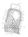
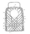
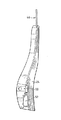
図面に言及し、本発明に従って製造された乗物シートフレームの1実施の形態を参照番号10で示す。シートフレーム10は、上面14,底面16及び両サイド18,20を有する本体12を含む。本体12はまた、前面22と背面24を有する。
Referring to the drawings, an embodiment of a vehicle seat frame manufactured in accordance with the present invention is indicated by
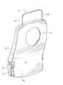
周辺リブ26は本体の両サイド及び上面に沿って延伸する。好ましくは、リブ26は外側周辺フランジ28と、内側周辺フランジ30を有し、これらの2つの周辺フランジは互いに離間している。一連のブリッジフランジ(渡しフランジ)32は外側及び内側周辺フランジの間に延伸し、好ましくは、これらの2つのフランジに対して斜めに配設されている。少なくとも1つ、好ましくは2つほぼ水平なフランジ34は本体12の前面から突出し、本体の低位置、好ましくは、シートに着座する人の腰の位置に配設される。一連の斜めフランジ36がまた前面に設けられている。前記水平フランジ及び斜めフランジは、1サイド側の内側周辺フランジから反対側のサイドの内側周辺フランジへと前面22の全体を横切って延伸する。図示の実施の形態に示すように、これらのフランジは、好ましくは、内側周辺フランジ30に隣接する端部において、中間部分42よりも大きな高さ(突き出し長さ)を持つ。本体12の上部領域に孔44が設けられている。この孔44は比較的大きく、該上部領域における本体12の端から端までの距離(横幅)の少なくとも1/3、好ましくは、約半分の直径を有する。孔の位置及びサイズはシートフレームの重心、究極的には組み上げられたシート全体の重心を下げるものである。これは、引いては、シートの衝突安全能力を高める。
The
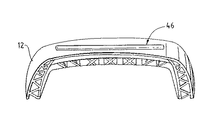
本発明のシートフレームは、好ましくは、ワンピースのダイキャスト部品として作られるが、ダイキャスト本体12をその多様性を高めるためにその他の構成要素と共に用いることとしてもよい。図示の実施の形態において、そういった多様性を高めることの1つは、いわゆる「ハイバック」シートと呼ばれる上部領域を支持するための上部延伸部46を使用することで達成される。上部延伸部46は管材料又は棒材から作られ、シートに採用するハイバッククッションの特定のサイズ及び形状に依存して多様な形状を持つことが出来る。上部延伸部46の垂直端部48,48を本体12に形成された適当な取付孔(図示省略)に単に挿入するだけで上部延伸部46を簡単に本体12の上面に組み付けることができる。
The seat frame of the present invention is preferably made as a one-piece die-cast part, but the die-
その他の機能を達成するために多様なキャビティを本体12の周辺に設けることとしてもよい。例えば、シートにアームレストを取り付けるための金物を収容するキャビティ50を各サイド18,20に配設することができる。同様に、フレームをシートサスペンション他のフレームパーツのような他のシート構成要素に組み付けることを可能にする切欠き52を設けることもできる。
Various cavities may be provided around the
上記説明は発明を定める特許請求の範囲の文言の意味を限定する目的ではない。根本的な変更でなければ、むしろ、構造、機能又は効果に関する変更も可能であり、そういった変更も特許請求の範囲によりカバーされることを意図するものである。 The above description is not intended to limit the meaning of the words in the claims that define the invention. Rather, changes in structure, function, or effect are possible insofar as they are not radical changes, and such changes are intended to be covered by the claims.
10 シートフレーム
12 本体
14 上面
16 底面
18,20 サイド
22 前面
24 背面
26 周辺リブ
28 外側周辺フランジ
30 内側周辺フランジ
34 水平フランジ
36 斜めフランジ
32 渡しフランジ
44 孔
DESCRIPTION OF
Claims (6)
前記本体の前記両サイド及び前記上面に隣接して前記本体前面に配設された外側周辺フランジと;
前記本体前面に配設され前記外側周辺フランジから離間され前記外側周辺フランジと同じ広がりを持つように延伸する内側周辺フランジと;
前記本体前面をほぼ水平に横切る少なくとも1つの水平フランジと;
前記本体前面を斜めに延伸する少なくとも2つの斜めフランジと;
を含んでなる乗物シートフレーム。 A one-piece type magnesium die-cutting body having a top surface, a bottom surface, both sides, a front surface and a back surface;
An outer peripheral flange disposed on the front surface of the main body adjacent to both sides and the upper surface of the main body;
An inner peripheral flange disposed on the front surface of the main body and extending to be spaced apart from the outer peripheral flange and coextensive with the outer peripheral flange;
At least one horizontal flange extending substantially horizontally across the front of the body;
At least two diagonal flanges extending diagonally at the front of the body;
Vehicle seat frame comprising.
Applications Claiming Priority (1)
| Application Number | Priority Date | Filing Date | Title |
|---|---|---|---|
| US10/825,598 US20050231019A1 (en) | 2004-04-15 | 2004-04-15 | Vehicle seat frame |
Publications (1)
| Publication Number | Publication Date |
|---|---|
| JP2005297950A true JP2005297950A (en) | 2005-10-27 |
Family
ID=34465813
Family Applications (1)
| Application Number | Title | Priority Date | Filing Date |
|---|---|---|---|
| JP2005065015A Pending JP2005297950A (en) | 2004-04-15 | 2005-03-09 | Vehicle seat frame |
Country Status (5)
| Country | Link |
|---|---|
| US (1) | US20050231019A1 (en) |
| JP (1) | JP2005297950A (en) |
| CN (1) | CN1683184A (en) |
| DE (1) | DE102005017061A1 (en) |
| GB (1) | GB2413070A (en) |
Cited By (5)
| Publication number | Priority date | Publication date | Assignee | Title |
|---|---|---|---|---|
| KR101162117B1 (en) * | 2010-06-01 | 2012-07-04 | 재단법인 전주기계탄소기술원 | Magnesium seat back frame |
| KR101482001B1 (en) * | 2009-07-27 | 2015-01-14 | 존슨 컨트롤스 테크놀러지 컴퍼니 | One-piece seat structures and method of forming |
| US10023087B2 (en) | 2013-08-28 | 2018-07-17 | Toyota Jidosha Kabushiki Kaisha | Vehicle seat |
| US10266085B2 (en) * | 2016-03-18 | 2019-04-23 | Acro Aircraft Seating Limited | Seat back |
| JP2024080370A (en) * | 2022-12-02 | 2024-06-13 | トヨタ紡織株式会社 | Manufacturing method of vehicle seat and vehicle back frame |
Families Citing this family (13)
| Publication number | Priority date | Publication date | Assignee | Title |
|---|---|---|---|---|
| US7131694B1 (en) * | 2005-04-29 | 2006-11-07 | Buffa John A | Adjustable lumbar support for vehicle seat |
| DE102005053948B4 (en) * | 2005-11-11 | 2017-01-19 | Fico Cables, Lda. | Support element with adjustable side supports |
| WO2010045571A1 (en) * | 2008-10-16 | 2010-04-22 | Johnson Controls Technology Company | One-piece seat structure and cold forming processes to create seat structures |
| IN2012DN01238A (en) * | 2009-08-04 | 2015-05-15 | Johnson Controls Tech Co | |
| CN102686447B (en) * | 2010-01-18 | 2015-04-01 | 李尔公司 | Seat assembly having a cross member |
| IT1402398B1 (en) * | 2010-10-21 | 2013-09-04 | Bonetti | BACKREST STRUCTURE, PARTICULARLY FOR CHAIRS. |
| BR112014011695A2 (en) * | 2011-12-26 | 2017-05-09 | Toray Industries | seat frame structure |
| DE102012214039A1 (en) * | 2012-05-29 | 2013-12-05 | Keiper Gmbh & Co. Kg | Backrest part for a seat, in particular a vehicle seat |
| DE102013220364A1 (en) * | 2013-07-22 | 2015-01-22 | Johnson Controls Components Gmbh & Co. Kg | BACKREST FOR A VEHICLE SEAT AND VEHICLE SEAT |
| DE102013021692A1 (en) * | 2013-12-19 | 2015-06-25 | GM Global Technology Operations LLC (n. d. Ges. d. Staates Delaware) | Automotive seat element |
| DE102017206751A1 (en) * | 2017-04-21 | 2018-10-25 | Lear Corporation | VEHICLE SEAT SYSTEM |
| CN111376805A (en) * | 2018-12-29 | 2020-07-07 | Sabic环球技术有限责任公司 | Plastic seat frames for electric vehicles |
| CA3267124A1 (en) * | 2022-09-08 | 2024-03-14 | Anthro Form, Llc | Chair having interchangeable decorative feature |
Family Cites Families (14)
| Publication number | Priority date | Publication date | Assignee | Title |
|---|---|---|---|---|
| US4088367A (en) * | 1977-06-20 | 1978-05-09 | Rohr Industries, Inc. | Vehicle seat assembly |
| US4588228A (en) * | 1983-08-05 | 1986-05-13 | Tachikawa Spring Co., Ltd. | Pan-type vehicle seat back mounted to a reclining mechanism |
| DE3841532A1 (en) * | 1988-12-09 | 1990-06-13 | Bayer Ag | BACKREST SUPPORT STRUCTURE FOR A VEHICLE SEAT AND VEHICLE SEAT BACKREST WITH THIS BACKREST SUPPORT STRUCTURE |
| GB2246699B (en) * | 1990-07-26 | 1994-02-09 | Autoliv Dev | Improvements in or relating to a seat frame |
| US5328248A (en) * | 1991-07-23 | 1994-07-12 | Toyota Jidosha Kabushiki Kaisha | Seat frame for a vehicle |
| US5897168A (en) * | 1995-07-28 | 1999-04-27 | Johnson Controls Technology Company | Vehicle seat frame |
| US5984419A (en) * | 1995-11-27 | 1999-11-16 | Lear Corporation | Automotive seat back |
| WO1998008705A1 (en) * | 1996-08-29 | 1998-03-05 | Lear Corporation | Vehicle seat assembly |
| AUPO274796A0 (en) * | 1996-10-04 | 1996-10-31 | Henderson's Industries Pty Ltd | Seat backrest frame |
| US5951110A (en) * | 1997-10-17 | 1999-09-14 | Irwin Seating Company | Contoured plastic seat back |
| AT3804U1 (en) * | 1999-05-27 | 2000-08-25 | Tcg Unitech Ag | SEATREST FOR A MOTOR VEHICLE |
| JP4477766B2 (en) * | 2000-10-30 | 2010-06-09 | 株式会社岡村製作所 | Chair backboard |
| US20040174056A1 (en) * | 2003-03-06 | 2004-09-09 | Sears Manufacturing Company | Inflatable seat cushion |
| US20040212242A1 (en) * | 2003-04-24 | 2004-10-28 | Dennis Gryp | Vehicle seat with internal anchors |
-
2004
- 2004-04-15 US US10/825,598 patent/US20050231019A1/en not_active Abandoned
-
2005
- 2005-03-07 CN CNA2005100515916A patent/CN1683184A/en active Pending
- 2005-03-09 GB GB0504848A patent/GB2413070A/en not_active Withdrawn
- 2005-03-09 JP JP2005065015A patent/JP2005297950A/en active Pending
- 2005-04-13 DE DE102005017061A patent/DE102005017061A1/en not_active Withdrawn
Cited By (5)
| Publication number | Priority date | Publication date | Assignee | Title |
|---|---|---|---|---|
| KR101482001B1 (en) * | 2009-07-27 | 2015-01-14 | 존슨 컨트롤스 테크놀러지 컴퍼니 | One-piece seat structures and method of forming |
| KR101162117B1 (en) * | 2010-06-01 | 2012-07-04 | 재단법인 전주기계탄소기술원 | Magnesium seat back frame |
| US10023087B2 (en) | 2013-08-28 | 2018-07-17 | Toyota Jidosha Kabushiki Kaisha | Vehicle seat |
| US10266085B2 (en) * | 2016-03-18 | 2019-04-23 | Acro Aircraft Seating Limited | Seat back |
| JP2024080370A (en) * | 2022-12-02 | 2024-06-13 | トヨタ紡織株式会社 | Manufacturing method of vehicle seat and vehicle back frame |
Also Published As
| Publication number | Publication date |
|---|---|
| DE102005017061A1 (en) | 2005-11-10 |
| CN1683184A (en) | 2005-10-19 |
| GB0504848D0 (en) | 2005-04-13 |
| US20050231019A1 (en) | 2005-10-20 |
| GB2413070A (en) | 2005-10-19 |
Similar Documents
| Publication | Publication Date | Title |
|---|---|---|
| JP2005297950A (en) | Vehicle seat frame | |
| JP6362948B2 (en) | Seat back frame | |
| CA2517822A1 (en) | Seat mount structure for saddle ride vehicle | |
| US11440452B2 (en) | Composite seat back | |
| JP2009126184A5 (en) | ||
| JP2006168422A (en) | Bumper frame structure of vehicle | |
| KR20170001117U (en) | light weight car seat with looking back | |
| CN103921699A (en) | Vehicle rear seat and manufacturing method thereof | |
| JP4346486B2 (en) | Headrest | |
| JP2018176766A (en) | Decorative body for vehicle seat and molding tool for the same | |
| JPH0716648U (en) | Vehicle seat pad structure | |
| JP2018095151A (en) | Slide rail support structure | |
| CN218198166U (en) | Rear trim part of vehicle | |
| CN216069711U (en) | Integrated seat basin of vehicle seat | |
| JP2016210296A (en) | Vehicular seat | |
| JP2021079826A (en) | Vehicle interior structure | |
| JP3544952B2 (en) | saddle | |
| JP4005821B2 (en) | Center hinge structure for vehicle rear seats | |
| JPH0729892Y2 (en) | Headrest | |
| JP4238725B2 (en) | Vehicle structure | |
| JP2535062Y2 (en) | Headrest | |
| JP2558827Y2 (en) | Motorcycle seat mounting structure | |
| JP4140680B2 (en) | Automotive interior parts | |
| JPH0129732B2 (en) | ||
| KR200437788Y1 (en) | Chair with steel frame |