JP2005297929A - Vehicular slip preventive supporting device - Google Patents
Vehicular slip preventive supporting device Download PDFInfo
- Publication number
- JP2005297929A JP2005297929A JP2004121271A JP2004121271A JP2005297929A JP 2005297929 A JP2005297929 A JP 2005297929A JP 2004121271 A JP2004121271 A JP 2004121271A JP 2004121271 A JP2004121271 A JP 2004121271A JP 2005297929 A JP2005297929 A JP 2005297929A
- Authority
- JP
- Japan
- Prior art keywords
- refrigerant
- tire
- road
- auxiliary device
- container
- Prior art date
- Legal status (The legal status is an assumption and is not a legal conclusion. Google has not performed a legal analysis and makes no representation as to the accuracy of the status listed.)
- Pending
Links
Images


Landscapes
- Tires In General (AREA)
Abstract
Description
この発明は、車輪タイヤの路面に対する摩擦係数を、タイヤを冷却することにより増加させる車両用スリップ防止補助装置に関する。 The present invention relates to an anti-slip auxiliary device for a vehicle that increases a coefficient of friction with respect to a road surface of a wheel tire by cooling the tire.
走行時の車輪タイヤの路面に対する摩擦係数を増大させる手段が種々提案されているが、かかる手段は一般に冬季路面の凍結路が対象であり、例えば特許文献1ではスリップ防止粒子を粒子保温手段により保温し、保温した粒子を凍結路面に付着させて凹凸を形成し、接触摩擦力を増加させる手段を示している。又、上記粒状物を散布する手段以外に、空気をタイヤに吹付けてタイヤの摩擦熱による温度上昇の防止を図る方法が特許文献2により提案されている。
Various means for increasing the coefficient of friction with respect to the road surface of the wheel tire during traveling have been proposed. Such means are generally intended for frozen roads in the winter road surface. For example, in Patent Document 1, the anti-slip particles are kept warm by the particle heat retaining means. The means for increasing the contact friction force is shown by forming the unevenness by attaching the heat-insulated particles to the frozen road surface. Further,
この特許文献2による自動車タイヤのスリップ防止法では、フエンダ部等に設けたノズルから外気より数度低下するように空気をタイヤに吹付けてタイヤの温度上昇を防止することを提案している。さらに凍結路でのスリップ時に車輪前方の路面を冷却してスリップを防止する方法が特許文献3により提案されている。このスリップ防止方法では、車輪のスリップを防止すべき状態を検出すると、車輪前方に気化熱により路面を冷却する冷却物質を放出し、車輪前方の路面を冷却するとされている。
In the slip prevention method for automobile tires according to
しかし、上記いずれの例も冬季路面の凍結路でのスリップ防止が対象であり、凍結路以外のWet路(路面が水で濡れた状態)や、冬季以外の一般的な乾燥状態の路面であるDry路に対しては効果が期待できない。スリップ防止粒子となる砂等を凍結路以外の路面で散布すると、砂粒等により却ってスリップし易くなり、又低温空気を路面に吹き付けても路面の熱容量が大きいため、タイヤを冷却する効果が薄いからである。摩擦係数μを増大させる手段は、凍結路は勿論のこと、Wet路、Dry路に対しても共通に利用できることが望ましいが、従来は主として凍結路を対象としており、凍結路、Wet路、Dry路のいずれであっても有効にスリップを防止する手段が求められている。
この発明は、上記の問題に留意して、凍結路、Wet路、又はDry路のいずれであってもタイヤ面を有効に冷却することによって、ブレーキ制動時その他の必要時にタイヤの路面に対する摩擦係数を増大させ得る車両用スリップ防止補助装置を提供することを課題とする。 In consideration of the above problems, the present invention effectively cools the tire surface, whether it is a frozen road, a wet road, or a dry road, so that the coefficient of friction with respect to the road surface of the tire when braking or other necessary is required. It is an object of the present invention to provide an anti-slip auxiliary device for a vehicle that can increase the motor.
この発明は、上記の課題を解決する手段として、車輪の外周辺に冷媒を収容した容器を配置し、この容器の冷媒をノズルからタイヤに吹付け、付着した冷媒の気化によりタイヤを冷却してタイヤの路面に対する摩擦係数を増大させるようにした車両用スリップ防止補助装置としたのである。 As a means for solving the above problems, the present invention arranges a container containing a refrigerant around the outer periphery of the wheel, sprays the refrigerant in the container from the nozzle onto the tire, and cools the tire by vaporizing the adhering refrigerant. This is an anti-slip auxiliary device for vehicles in which the coefficient of friction with respect to the road surface of the tire is increased.
上記の構成としたこの発明の車両用スリップ防止補助装置によれば、冷媒をタイヤ表面(外周面)又は側面に吹付けると、その冷媒の気化によりタイヤを冷却することができ、これによりタイヤの路面に対する摩擦係数を増大させることができる。冷媒は容器内に所定圧力で液化されて収容されており、容器の開口を開放すれば噴射ノズルから霧状(液滴状)で噴射され、タイヤ表面又は側面に瞬時に付着し、付着した冷媒が気化することによりタイヤから熱を奪ってタイヤが冷却される。タイヤ表面又は側面を冷却すると、凍結路、Wet路、又はDry路のいずれであれ、タイヤの路面に対する摩擦係数が増大する。 According to the vehicle slip prevention auxiliary device of the present invention having the above-described configuration, when the coolant is sprayed on the tire surface (outer peripheral surface) or the side surface, the tire can be cooled by vaporization of the coolant. The coefficient of friction against the road surface can be increased. The refrigerant is liquefied and stored in the container at a predetermined pressure. If the opening of the container is opened, the refrigerant is sprayed from the spray nozzle in the form of a mist (droplet) and instantly adheres to the tire surface or side surface. As a result of vaporization, the tire is cooled by removing heat from the tire. When the tire surface or side surface is cooled, the friction coefficient with respect to the road surface of the tire increases whether it is a frozen road, a wet road, or a dry road.
ゴム高分子材料を用いたタイヤの摩擦力は、タイヤゴムの粘着力(接着力)とタイヤゴムが路面の凹凸による伸縮で繰り返される変形に伴う摩擦仕事に対応するヒステリシス分力とから成り、一般に粘着力がヒステリシス分力より数倍大きく、かつヒステリシス分力は高温から低温(0℃付近)に冷却されてもわずかに増大するだけであるが、粘着力は低温になる程増大し、従って摩擦係数が増大する。このため、凍結路、Wet路、あるいはDry路のいずれであれタイヤ表面を冷却して低温にする程摩擦係数が大きくなる。このため、この発明ではタイヤ表面又は側面に冷媒を積極的に吹付けて、摩擦係数の増大が十分有効な値となるようにしたのである。 The frictional force of a tire using a rubber polymer material consists of the adhesive force (adhesive force) of the tire rubber and the hysteresis component that corresponds to the frictional work caused by repeated deformation of the tire rubber due to the expansion and contraction caused by the unevenness of the road surface. Is several times larger than the hysteresis component, and the hysteresis component increases only slightly even when cooled from a high temperature to a low temperature (near 0 ° C.), but the adhesive force increases as the temperature decreases, so the coefficient of friction increases. Increase. For this reason, the friction coefficient increases as the tire surface is cooled to a low temperature, whether it is a frozen road, a wet road, or a dry road. For this reason, in the present invention, the coolant is positively sprayed on the tire surface or side surface so that the increase in the friction coefficient becomes a sufficiently effective value.
走行路面が凍結路、Wet路である場合は、路面の温度が一般に低く単に冷媒を吹付面が路面に接地する直前に吹付ければよいが、Dry路では大気中に含まれる水分が冷媒の吹付けでタイヤの吹付面の気化、冷却による温度低下で結露してタイヤ表面が濡れ、却って摩擦係数μが小さくなりスリップする場合がある。従って、凍結路、Wet路の場合は、車両の進行方向の前方から後向きに車輪のタイヤ面に向って、又Dry路の場合は結露した水分が蒸発、飛散により除去されるよう路面への接地を時間的に遅らせるため、車輪の後方から前方のタイヤ面に向って冷媒を噴射できるように冷媒噴射ユニットを両方の位置に設け、路面の状態によってそのいずれかを選択的に作動させるのが望ましい。 When the traveling road surface is a frozen road or a wet road, the temperature of the road surface is generally low, and it is only necessary to spray the refrigerant just before the spraying surface contacts the road surface. However, on the Dry road, moisture contained in the atmosphere is blown by the refrigerant. In some cases, the surface of the tire is vaporized and the temperature decreases due to cooling, so that the tire surface gets wet and the friction coefficient μ decreases and slipping may occur. Therefore, in the case of icy roads and wet roads, the road is grounded from the front in the direction of travel of the vehicle toward the tire surface of the wheels, and in the case of dry roads, the condensed water is removed by evaporation and scattering. It is desirable to provide a refrigerant injection unit at both positions so that the refrigerant can be injected from the rear of the wheel toward the front tire surface, and selectively operate one of them depending on the road surface condition. .
この発明の車両用スリップ防止補助装置は、路面が凍結路、Wet路、又はDry路のいずれであれ、冷媒をノズルからタイヤに積極的に吹付けて付着した冷媒の気化によりタイヤを冷却し、摩擦係数を増大させるようにしたから、タイヤの路面に対する摩擦力が有効に飛躍的に増大し、ブレーキ制動時やその他の必要時に応じて確実に摩擦力が向上し、制動距離の短縮や、スリップ防止による旋回性能の向上を可能とする効果が得られる。 The vehicle anti-slip auxiliary device of the present invention cools the tire by vaporizing the attached refrigerant by actively spraying the refrigerant from the nozzle to the tire regardless of whether the road surface is a frozen road, a wet road, or a dry road. Since the friction coefficient is increased, the frictional force on the road surface of the tire is effectively increased dramatically, and the frictional force is reliably improved according to braking and other necessary times, shortening the braking distance and slipping. The effect which improves the turning performance by prevention is acquired.
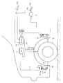
以下、この発明の実施の形態について図面を参照して説明する。図1は実施形態の車両用スリップ防止補助装置の全体概略構成図を示す。図1では、冷媒噴射ユニットA1 、A2 を前輪の1輪の前後に設けた例を示しているが、他の前輪及び後輪に対しても同様に設けられる。但し、冷媒噴射ユニットA1 とA2 は全く同一の構成、機能であり、以下では主としてA1 を代表させて説明する。図示のように、冷媒噴射ユニットA1 は、制御回路(ECU)10からの制御信号を駆動回路11へ送り、駆動ラインLcからの電源信号で後述するソレノイド4を駆動して作動するように接続されて車両用スリップ防止補助装置が構成されている。但し、後述するように、冷媒噴射ユニットA1 、A2 と同一構成、作用の他の冷媒噴射ユニットA3 、A4 を用いる場合もある。
Embodiments of the present invention will be described below with reference to the drawings. FIG. 1 is an overall schematic configuration diagram of a vehicular slip prevention auxiliary apparatus according to an embodiment. Although FIG. 1 shows an example in which the refrigerant injection units A 1 and A 2 are provided on the front and rear of one front wheel, the refrigerant injection units A 1 and A 2 are similarly provided on the other front and rear wheels. However, the refrigerant injection units A 1 and A 2 have exactly the same configuration and function, and in the following, A 1 will be mainly described as a representative. As shown in the figure, the refrigerant injection unit A 1 is connected so as to operate by sending a control signal from the control circuit (ECU) 10 to the
制御回路10へは車輪速度センサS1 〜S4 、ブレーキ装置のブレーキペダルPDB のブレーキ圧検出器SB (但し、ブレーキ踏力検出器でも可)、アクセルのアクセルペダルPDA の作動を検出するアクセル検出器SA のそれぞれの検出信号が入力される。制御回路10には、後述するように走行路面が凍結路、Wet路、あるいはDry路であるかを、ブレーキ作動時のブレーキ圧検出器SB 、車輪速度センサS1 〜S4 からの信号、及び図示しないが加速度センサ(減速度)及び外気の温度センサ等からの信号に基づいて判定するプログラムを含むものとする。但し、そのプログラムの内容がこの発明の主要部ではないから、詳細な説明は省略する。又、上記判定プログラムの判定結果により、後述するように、他の冷媒噴射ユニットA2 又はA3 、さらにA4 を作動させる場合もある。
Control the wheel speed sensors S 1 to S 4 is the
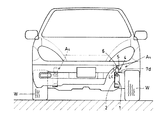
冷媒噴射ユニットA1 の詳細構成については後述するが、その取付位置は、図示の例では車輪Wの外周付近で、その接続パイプ8の端末の噴射ノズル8bから冷媒を車輪(前輪)Wのタイヤ進行方向の前方から後方に向ってタイヤトレッド面に噴射するのに適する車体フレーム等の適宜位置に設置する。なお、冷媒噴射ユニットA2 は、Dry路に対応するために前方の冷媒噴射ユニットA1 と全く同一構成のものを車輪WのA1 に対向する後方位置に設けている。これは、Dry路ではタイヤに結露した水分が蒸発、飛散により除去されるよう路面への接地を時間的に遅らせることができるような位置として設定したからである。さらに、冷媒噴射ユニットA3 のように、タイヤ舵角軸心付近上にノズルを配置して舵角によってタイヤ面へ噴射するノズル位置を動かす必要をなくしてもよい。
Although the detailed configuration of the refrigerant injection unit A 1 will be described later, the mounting position thereof is in the vicinity of the outer periphery of the wheel W in the illustrated example, and refrigerant is supplied from the
冷媒噴射ユニットA1 は、図2に示すように、冷媒を収容した冷媒容器として冷媒スプレ缶1を保持器2に対し弾性を有するその保持バンド2aにより着脱自在に装着し、その上方の取付座3上に電磁コイル5、プランジャ6から成るソレノイド4と、冷媒を外部へ導出するためのノズルチップ7を備えている。プランジャ6は図中のばねによりコイルへの非通電時は上方に押上げられている。カバー(又はヨーク)5a内に設けられた電磁コイル5へは電源信号が駆動ラインLcから送られ、発生した電磁力でプランジャ6の下方に向けて端板4aを貫通して設けた突出ロッド6aを下方に押下げ、これによりノズルチップ7を下方へ押下げてノズルチップ7の弁座7aの斜面を冷媒スプレ缶1の噴射パイプ1aに当接させ、噴射パイプ1aを押下げると噴射パイプ1aから圧送される冷媒がノズルチップ7内の導通孔7bを通り、接続パイプ8へと送られるように設けられている。
As shown in FIG. 2, the refrigerant injection unit A 1 is detachably mounted with a refrigerant spray can 1 as a refrigerant container containing a refrigerant by a
ノズルチップ7は、図示省略しているが、通常(非通電時)は取付座3に設けた弾性部材のばね(例えば皿ばね)の力で、図2に示す上方の位置に押圧されており、冷媒を噴射する際はこのばね力及びプランジャ6のばね力に打勝ってノズルチップ7を端面7cに沿って下方に押下げ得る電磁力をソレノイド4は発生するものとする。接続パイプ8は、一端がノズルチップ7の導通孔7bに嵌合、接続され、他端は噴射ノズル8bとして形成されている。但し、後述する冷媒噴射ユニットA4 では接続パイプ8は省略され、ノズルチップ7の端に噴射ノズル7dが設けられている。
The
冷媒スプレ缶1内に収容されている冷媒は、図示の例ではフロン134a(HFC134a)(いわゆる代替フロン)が用いられる。このフロン134aは、塩素Cl成分を含まず、従ってオゾン層を破壊する危険が全くなく、沸点が−26℃以下で、常温での貯蔵圧力が6kgf/cm2 と低く、常温の大気中に放出されると速やかに気化するという性質を有し、比較的簡易に十分な安全性を確保できるという利点を有する。但し、冷媒としてはフロン134aは一例であり、他のフロン系冷媒、あるいは非フロン系の冷媒でもよく、タイヤ表面(外周面)又は側面に吹付けてタイヤを冷却する作用を有する冷却物質であればよい。 As the refrigerant accommodated in the refrigerant spray can 1, in the illustrated example, chlorofluorocarbon 134a (HFC134a) (so-called alternative chlorofluorocarbon) is used. This chlorofluorocarbon 134a does not contain a chlorine Cl component, and therefore has no danger of destroying the ozone layer, has a boiling point of −26 ° C. or lower, and has a low storage pressure of 6 kgf / cm 2 at room temperature, and is released into the atmosphere at room temperature. If it is done, it has the property of vaporizing quickly, and has the advantage that sufficient safety can be secured relatively easily. However, as the refrigerant, chlorofluorocarbon 134a is an example, and other chlorofluorocarbon refrigerants or non-fluorocarbon refrigerants may be used, and any coolant that acts on the tire surface (outer peripheral surface) or side surface to cool the tire can be used. That's fine.
上記のように構成したこの実施形態の車両用スリップ防止補助装置は、着脱自在、即ちワンタッチで装着可能な冷媒スプレ缶1を装着してスリップ防止のための冷媒の噴射の可能な状態で走行中に作動させる。ブレーキ作動時に走行路が凍結路、又はWet路であることを前述した各種センサ、検出器からの検出信号により制御回路10の所定のプログラムで判定すると、その制御信号の指令により前方の冷媒噴射ユニットA1 が作動して冷媒が噴射ノズル8bから噴射され、タイヤ表面が冷却される。このため、タイヤの路面に対する摩擦係数μが増大し、制動効果が大きくなる。冷媒噴射は、前述したように、ソレノイド4が作動するとプランジャ6の突出ロッド6aでノズルチップ7を押し下げ、これにより冷媒スプレ缶1の噴射パイプ1aを押し下げて冷媒を噴射し、ノズルチップ7から接続パイプ8を経て噴射ノズル8bより噴射される。
The vehicle anti-slip auxiliary device according to this embodiment configured as described above is mounted in a state where the refrigerant spray can 1 is detachably attached, that is, can be attached with a single touch, and the refrigerant can be injected to prevent slipping. To operate. When a predetermined program of the
一方、ブレーキ作動時に走行路がDry路であることを制御回路10で判定すると、前方の冷媒噴射ユニットA1 を作動させた場合、一般に外気が冬期より高いため湿度が高く、タイヤを冷媒の噴射により冷却すると外気に含まれる水分がタイヤ表面に結露して濡れるため、逆に摩擦係数μが低下する可能性が高くなる。従って、Dry路でのブレーキ作動時には前方の冷媒噴射ユニットA1 ではなく、後方の冷媒噴射ユニットA2 を制御回路10で選択し、その制御回路からの指令を後方の冷媒噴射ユニットA2 へ送り、タイヤ表面に後方から噴射する。
On the other hand, when the
これは、前述したように、タイヤ後方からタイヤ表面に噴射することによりその噴射面が接地するまでの時間を遅らせ、その間に結露による水分の蒸発又は遠心力による水分の飛散によりタイヤの濡れを減少させ、冷却効果を保持して摩擦係数μの増大を図るためである。なお、上記例ではDry路の場合、後方の冷媒噴射ユニットA2 を使用するとしたが、図3に示すように冷媒噴射ユニットA4 を車両のタイヤより内側に設置し、タイヤ表面に近いタイヤ側面に冷媒を噴射させてタイヤ表面を冷却するようにしてもよい。 As described above, by spraying the tire surface from the rear of the tire, the time until the injection surface contacts the ground is delayed, and during that time, moisture is evaporated due to condensation or moisture is scattered due to centrifugal force to reduce tire wetting. This is to maintain the cooling effect and increase the friction coefficient μ. In the above example, in the case of a dry road, the rear refrigerant injection unit A 2 is used. However, as shown in FIG. 3, the refrigerant injection unit A 4 is installed on the inner side of the vehicle tire, and the tire side surface close to the tire surface. The tire surface may be cooled by injecting the coolant.
上記各例では冷媒のタイヤ表面又は側面への噴射によってタイヤ表面を冷却し、これによりタイヤの路面に対する摩擦係数μを増大させるとしたが、これはタイヤの技術分野における次のような説明(例えば技術誌「タイヤの話」服部六郎著、大成社)に基づいている。即ち、タイヤの摩擦力Fは、タイヤのゴム高分子材料の粘着力FA (又は接着力、Adhesion)と、タイヤ表面が路面の凹凸によって繰り返し変形して摩擦仕事として消費されるヒステリシス(Hysteresis)損失に対応するヒステリシス分力FH とに分けられるが、一般に粘着力FA の占める割合の方がヒステリシス分力FH より数倍大きい。そして、Dry路で高温の場合は、それぞれの分力に対する摩擦係数μは共に低下するが、特に粘着力の摩擦係数はその低下が著しくなり、反対にタイヤの温度が低くなる程急激に大きくなる。 In each of the above examples, the tire surface is cooled by injecting the coolant onto the tire surface or side surface, thereby increasing the coefficient of friction μ with respect to the road surface of the tire. Based on the technical journal “Tire Story” written by Rokuro Hattori and Taiseisha. That is, the tire friction force F includes the tire rubber polymer material adhesive force F A (or adhesion), and the hysteresis that the tire surface is repeatedly deformed by road surface irregularities and consumed as friction work (Hysteresis). The hysteresis component force F H corresponding to the loss is generally divided, but the ratio of the adhesive force F A is generally several times larger than the hysteresis component force F H. When the temperature is high on the dry road, the friction coefficient μ with respect to each component force decreases. In particular, the friction coefficient of the adhesive force decreases remarkably, and conversely increases as the tire temperature decreases. .
これに対してヒステリシス分力による摩擦係数は低温である程大きいが、高温では少し低下する程度であり、比較的その変化の割合は小さい。従って、凍結路、Wet路であれば、タイヤの温度は比較的低く、又は低くなるため粘着力による摩擦係数が大となるが、冷媒の噴射によりタイヤ表面の温度をさらに低くすることにより益々摩擦係数は大となる。一方、Dry路で高温の場合、粘着力は大きく減少し、この場合にタイヤ表面に冷媒を噴射することにより冷却すれば、摩擦力が大きく回復することとなる。 On the other hand, the coefficient of friction due to the hysteresis component force increases as the temperature decreases, but decreases slightly at a high temperature, and the rate of change is relatively small. Therefore, if the road is frozen or wet, the temperature of the tire is relatively low or low, so the coefficient of friction due to the adhesive force is large. However, the friction is increased by further lowering the temperature of the tire surface by injecting the refrigerant. The coefficient is large. On the other hand, when the temperature is high on the Dry road, the adhesive force is greatly reduced. In this case, if the coolant is cooled by spraying the coolant onto the tire surface, the frictional force is greatly recovered.
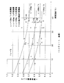
又、他の技術誌(「路面のすべりとその対策」市原薫、小野田光之著、技術書院、平成9年3月25日発行(第1刷))によれば、路面の温度とすべり摩擦係数fとの関係を図4、図5に示すように、実測値で示されており、上述した変化が分かる。図中の曲線は次の実験式で表される。
・コンクリート、湿潤路(図4)
f=0.000105t2 +0.00002 vt−0.0111t+0.000056v2 −0.0117v+1.19
・コンクリート、乾燥路(図5)
f=0.000139t2 +0.00003 vt−0.0113t+0.00005 v2 −0.0066v+1.11
In addition, according to other technical journals ("Slip on the road surface and its countermeasures", Jun Ichihara, Mitsuyuki Onoda, Technical Shoin, published on March 25, 1997 (first printing)), the temperature of the road surface and the sliding friction. As shown in FIGS. 4 and 5, the relationship with the coefficient f is shown as an actual measurement value, and the change described above can be seen. The curve in the figure is expressed by the following empirical formula.
・ Concrete, wet road (Fig. 4)
f = 0.000105t 2 +0.00002 vt−0.0111t + 0.000056v 2 −0.0117v + 1.19
・ Concrete, dry road (Fig. 5)
f = 0.000139t 2 +0.00003 vt−0.0113t + 0.00005 v 2 −0.0066v + 1.11
上記研究によれば、乾燥路面では路面温度が0℃近く、しかも走行速度が40km/hより小さい場合、比較的大きな摩擦係数値が得られ(P18)、温度の摩擦係数に対する影響は、温度の低いところでは1℃増大するごとに摩擦係数は約0.01減少する。この傾向は温度の上昇と共に小さくなり、40℃付近では温度変化の影響はほとんど0になる(P22)。一方、湿潤路面ではほぼ乾燥路の場合と同様であり、温度の低いところでは1℃増大するごとに摩擦係数は約0.01減少する。この傾向は温度の上昇とともに小さくなり、50℃付近では温度変化の影響はほとんど0となる(P23)。 According to the above research, when the road surface temperature is close to 0 ° C. and the traveling speed is less than 40 km / h on a dry road surface, a relatively large friction coefficient value is obtained (P18). At low temperatures, the coefficient of friction decreases by about 0.01 for every 1 ° C increase. This tendency becomes smaller as the temperature rises, and the influence of the temperature change becomes almost 0 near 40 ° C. (P22). On the other hand, the wet road surface is almost the same as in the dry road, and the coefficient of friction decreases by about 0.01 each time the temperature increases by 1 ° C. This tendency becomes smaller as the temperature rises, and the influence of the temperature change becomes almost 0 near 50 ° C. (P23).
なお、この実施形態では各冷媒噴射ユニットA1 〜A4 の作動は、急ブレーキ時を要件としている。この急ブレーキ要件とは、例えば通常走行中、あるいは低速走行中(20〜10km/H程度以下)に緊急制動を必要とする場合、又前方障害物と衝突の可能性がある場合、交差点進入直前に信号機が赤信号に変化したことに気付くのが遅れた場合、カーブした道路でカーブを曲り切れずにガードレールと衝突の可能性がある場合等である。 In this embodiment, the operation of each of the refrigerant injection units A 1 to A 4 is required during sudden braking. This sudden braking requirement is, for example, when emergency braking is required during normal driving or low speed driving (about 20 to 10 km / H or less), or when there is a possibility of collision with a front obstacle, immediately before entering the intersection. When it is late to notice that the traffic light has changed to a red light, there is a possibility of collision with the guardrail without being able to turn the curve on a curved road.
このような急ブレーキ要件を制御回路10に含まれるプログラムで判断すると共に、このプログラムには冷媒噴射による冷却効果を上げるため、次のようなプログラムも含む。即ち、アクセルペダルPDA を急に離した場合、アクセル検出器SA によるその状態を検出した信号を制御回路10に送り、次に急ブレーキが行なわれてブレーキペダルPDB の踏込みにより生じる信号がブレーキ圧検出器SB から送られて来ることを予測して所定時間のタイムラグを設け、その信号が来れば冷媒噴射ユニットA1 〜A4 のうちの所定のユニットを作動させ、その間に急ブレーキの信号が送られて来ない場合は作動させず、又所定時間内に急ブレーキ信号が送られて来たが、その後直ちに急ブレーキ信号が無くなった場合は作動を直ちに停止させるプログラムを含むものとする。
Such a sudden braking requirement is determined by a program included in the
さらに、上記プログラムには冷媒噴射ユニットA1 〜A4 のそれぞれの作動時間を各別に積算し、冷媒スプレ缶内の現在の残量を演算により算出して推定し、残量小となれば警告信号を送り音声又は表示ランプ等により警告をして冷媒スプレ缶1の交換を促すようなプログラムも含むものとする。又、上記実施形態では、冷媒噴射ユニットA1 〜A4 を作動させるのは、ブレーキ作動時として説明したが、例えば急発進時や急加速、あるいは旋回操舵を必要とする走行中の特定条件下で作動させてもよく、それぞれの場合に摩擦係数μが増大すればそれだけ急発進、急加速、急旋回が効果的に行なえることとなる。 Further, in the above program, the operation time of each of the refrigerant injection units A 1 to A 4 is accumulated separately, the current remaining amount in the refrigerant spray can is calculated and estimated, and a warning is given if the remaining amount is low. A program that sends a signal and gives a warning by voice or a display lamp or the like to prompt replacement of the refrigerant spray can 1 is also included. In the above-described embodiment, the refrigerant injection units A 1 to A 4 are operated when the brake is operated. However, for example, a specific condition during traveling that requires sudden start, sudden acceleration, or turning steering is used. In each case, if the friction coefficient μ increases, sudden start, sudden acceleration, and sudden turn can be effectively performed.
以上の実施形態では車両の前進時を前提として説明したが、シフトレバーがバック(後退位置)に入れられた場合、シフトレバーのバック位置の信号を制御回路10へ送り、その信号により前方の冷媒噴射ユニットA1 と後方の冷媒噴射ユニットA2 を前進時とは逆に動作させるように制御する。これにより凍結路、Wet路、又はDry路のいずれであれ、前進、後退のどちらでも摩擦係数を増加させることが可能となる。
The above embodiment has been described on the assumption that the vehicle is moving forward. However, when the shift lever is put in the back (reverse position), a signal of the back position of the shift lever is sent to the
さらに、上記実施形態では冷媒を収容する容器はワンタッチで着脱自在のスプレ缶方式の容器としたが、スプレ缶に替えて固定式のボンベを冷媒収容容器として保持器2により固定して設け、あるいはボンベを運転席内の適宜位置等に固定し、このボンベに接続パイプを接続し、パイプ端末から冷媒を送液できるようにして、冷媒が無くなると充填できる充填形式の容器にしてもよい。
Further, in the above-described embodiment, the container for storing the refrigerant is a spray can type container that is detachable with a single touch, but instead of the spray can, a fixed cylinder is fixed as the refrigerant container by the
この発明の車両用スリップ防止補助装置は、冷媒を積極的に吹付けてタイヤの路面に対する摩擦係数を増大させる機能を有するから、タイヤで走行するあらゆる種類の車両に広く利用することができる。 The vehicle anti-slip auxiliary device of the present invention has a function of increasing the coefficient of friction with respect to the road surface of the tire by positively spraying the refrigerant, and thus can be widely used for all kinds of vehicles that run on the tire.
1 スプレ缶
2 保持器
3 取付座
4 ソレノイド
5 電磁コイル
6 プランジャ
7 ノズルチップ
8 接続パイプ
10 制御回路
11 駆動回路
A1 〜A4 冷媒噴射ユニット
W 車輪
S1 〜S4 車輪速度センサ
SA アクセル検出器
SB ブレーキ圧検出器
Lc 駆動ライン
1 spray can 2
Claims (6)
Priority Applications (1)
| Application Number | Priority Date | Filing Date | Title |
|---|---|---|---|
| JP2004121271A JP2005297929A (en) | 2004-04-16 | 2004-04-16 | Vehicular slip preventive supporting device |
Applications Claiming Priority (1)
| Application Number | Priority Date | Filing Date | Title |
|---|---|---|---|
| JP2004121271A JP2005297929A (en) | 2004-04-16 | 2004-04-16 | Vehicular slip preventive supporting device |
Publications (1)
| Publication Number | Publication Date |
|---|---|
| JP2005297929A true JP2005297929A (en) | 2005-10-27 |
Family
ID=35329977
Family Applications (1)
| Application Number | Title | Priority Date | Filing Date |
|---|---|---|---|
| JP2004121271A Pending JP2005297929A (en) | 2004-04-16 | 2004-04-16 | Vehicular slip preventive supporting device |
Country Status (1)
| Country | Link |
|---|---|
| JP (1) | JP2005297929A (en) |
Cited By (6)
| Publication number | Priority date | Publication date | Assignee | Title |
|---|---|---|---|---|
| DE102009020657A1 (en) | 2009-05-08 | 2010-11-18 | Daimler Ag | Method for increasing friction value between vehicle tire and roadway during e.g. snow condition, involves attaching friction value-increasing articles i.e. steel pins, at vehicle tire during driving operation |
| DE102010037835A1 (en) * | 2010-09-28 | 2012-03-29 | Schrader T + A Fahrzeugbau Gmbh & Co. Kg | Vehicle e.g. tank lorry, has tank comprising outlet through which liquid for improving sliding properties of wheels flows out from tank, and valve selectively opening or closing outlet such that liquid is fed on region of wheels |
| KR101483088B1 (en) * | 2014-02-25 | 2015-01-19 | 아주자동차대학 산학협력단 | Spray chain device In a car to Spraying or Cleaning |
| CN104742643A (en) * | 2015-03-26 | 2015-07-01 | 重庆交通大学 | Multifunctional automobile wheel |
| CN110375517A (en) * | 2019-07-23 | 2019-10-25 | 交通运输部公路科学研究所 | A kind of brake rim cooling system |
| WO2024011986A1 (en) * | 2022-07-14 | 2024-01-18 | 中国第一汽车股份有限公司 | Antiskid method, system and apparatus, and non-volatile storage medium |
-
2004
- 2004-04-16 JP JP2004121271A patent/JP2005297929A/en active Pending
Cited By (7)
| Publication number | Priority date | Publication date | Assignee | Title |
|---|---|---|---|---|
| DE102009020657A1 (en) | 2009-05-08 | 2010-11-18 | Daimler Ag | Method for increasing friction value between vehicle tire and roadway during e.g. snow condition, involves attaching friction value-increasing articles i.e. steel pins, at vehicle tire during driving operation |
| DE102010037835A1 (en) * | 2010-09-28 | 2012-03-29 | Schrader T + A Fahrzeugbau Gmbh & Co. Kg | Vehicle e.g. tank lorry, has tank comprising outlet through which liquid for improving sliding properties of wheels flows out from tank, and valve selectively opening or closing outlet such that liquid is fed on region of wheels |
| KR101483088B1 (en) * | 2014-02-25 | 2015-01-19 | 아주자동차대학 산학협력단 | Spray chain device In a car to Spraying or Cleaning |
| CN104742643A (en) * | 2015-03-26 | 2015-07-01 | 重庆交通大学 | Multifunctional automobile wheel |
| CN104742643B (en) * | 2015-03-26 | 2017-01-18 | 重庆交通大学 | Multifunctional automobile wheel |
| CN110375517A (en) * | 2019-07-23 | 2019-10-25 | 交通运输部公路科学研究所 | A kind of brake rim cooling system |
| WO2024011986A1 (en) * | 2022-07-14 | 2024-01-18 | 中国第一汽车股份有限公司 | Antiskid method, system and apparatus, and non-volatile storage medium |
Similar Documents
| Publication | Publication Date | Title |
|---|---|---|
| US6170594B1 (en) | Method and apparatus for reducing vehicle rollover | |
| CA2498099C (en) | Hybrid vehicle slip stop device | |
| US7213687B2 (en) | Emergency braking apparatus for vehicle | |
| CN103079916B (en) | Method for securing a vehicle with an automatic parking brake | |
| US5350035A (en) | Antihydroplaning system for a motor vehicle | |
| JPH10507145A (en) | Wheel car | |
| JP2009113803A (en) | Driver assistance system | |
| US10272277B2 (en) | Apparatus, system and method for extinguishing a fire over the rear axle of a truck trailer | |
| CN101356087B (en) | System for controlling a service brake of a vehicle | |
| JP2005014781A (en) | Slip prevention device for vehicle | |
| TW201836885A (en) | Controller, control method and brake system | |
| JP2005297929A (en) | Vehicular slip preventive supporting device | |
| JP2004161119A (en) | Travel stabilizer for vehicle | |
| JP2005029143A (en) | Braking device for vehicle | |
| US6447009B1 (en) | Emergency vehicle braking system employing adhesive substances | |
| KR20220117356A (en) | Road anti-skid system on black ice (snow, rain) | |
| FI108418B (en) | Procedure and device for vehicle safety device | |
| JP4389244B2 (en) | Vehicle contact surface frictional force improving device | |
| JPH07309101A (en) | Auxiliary device and method for preventing slip of vehicle | |
| US20040182656A1 (en) | Vehicle slip stop device | |
| JPH06293202A (en) | Vehicle slip prevention method and device | |
| JP3589031B2 (en) | Travel control device for vehicles | |
| KR100799854B1 (en) | Automotive auxiliary braking system using compressed air | |
| FI95224C (en) | Active Double System | |
| JP2003146198A (en) | Braking control device |