JP2005297897A - Vehicle seat - Google Patents
Vehicle seat Download PDFInfo
- Publication number
- JP2005297897A JP2005297897A JP2004120256A JP2004120256A JP2005297897A JP 2005297897 A JP2005297897 A JP 2005297897A JP 2004120256 A JP2004120256 A JP 2004120256A JP 2004120256 A JP2004120256 A JP 2004120256A JP 2005297897 A JP2005297897 A JP 2005297897A
- Authority
- JP
- Japan
- Prior art keywords
- seat
- seat cushion
- hinge
- vehicle
- cushion
- Prior art date
- Legal status (The legal status is an assumption and is not a legal conclusion. Google has not performed a legal analysis and makes no representation as to the accuracy of the status listed.)
- Pending
Links
Images


Landscapes
- Seats For Vehicles (AREA)
Abstract
Description
本発明は、車両用シートに関する。 The present invention relates to a vehicle seat.
従来より、車両用シートのシートバックを後傾させてフラットなシート面を形成できるようにしたものが知られている。また、シートバックを前傾させてシートクッションに接するように折り畳むことができるものもある。 2. Description of the Related Art Conventionally, there has been known a vehicle seat that can form a flat seat surface by tilting the seat back of the vehicle seat backward. In some cases, the seat back can be folded so that the seat back is in contact with the seat cushion.
シートを3列備える車両では、各シートの配置や折り畳み方を工夫することで、多彩なシートアレンジが実現されている。 In vehicles equipped with three rows of seats, various seat arrangements are realized by devising the arrangement and folding of each seat.
シートを2列備える車両においても、1列目および2列目のシートバックを後傾させることで、比較的広い平坦なシート面を得ることができる。しかしながら、1列目のシートを通常どおりに使用している状況では、2列目シートのみで対応せざるを得ず、あまり広い平坦面は得られない。また、2列目シートのみの自由度しかない状況では、シートアレンジも限られたものとなる。 Even in a vehicle having two rows of seats, a relatively wide flat seat surface can be obtained by tilting the seat backs of the first row and the second row backward. However, in a situation where the first row sheet is used as usual, it is necessary to deal with only the second row sheet, and a very wide flat surface cannot be obtained. Further, in a situation where there is only a degree of freedom of the second row seat, the seat arrangement is also limited.
一方、従来より、シートの下に引き出し可能な補助シートを設けた車両や、2列目シートの後部に折り畳み式の車両用ベッドを設けた車両が提案されている(特許文献1、2参照)。
しかしながら、補助シートやベッドを備えたものでは、それらを装備する分、構成が複雑化し、製造コストも増大してしまうという問題があった。 However, those equipped with auxiliary sheets and beds have a problem that the configuration becomes complicated and the manufacturing cost increases because they are equipped.
そこで、本発明は、より簡素な構成の車両用シートによって、より広いシート面や、より多彩なシートアレンジを得ることを目的とする。 Accordingly, an object of the present invention is to obtain a wider seat surface and more various seat arrangements with a vehicle seat having a simpler configuration.
本発明は、シートクッションとシートバックとを備える車両用シートにおいて、上下に積層され前端部でヒンジを介して相互に接続される上側シートクッションと下側シートクッションとを備え、該ヒンジを支点として該上側シートクッションと下側シートクッションとを展開することにより、下側シートクッションを露出自在としたことを最も主要な特徴とする。 The present invention relates to a vehicle seat including a seat cushion and a seat back, and includes an upper seat cushion and a lower seat cushion that are stacked one above the other and connected to each other via a hinge at a front end portion, and the hinge serves as a fulcrum. The main feature is that the lower seat cushion can be exposed by developing the upper seat cushion and the lower seat cushion.
本発明によれば、二つのシートクッションを上下に積層し、そのうち下側のシートクッションをシート要素として利用できるようにしたので、より広い平坦なシート面、及びより多彩なシートアレンジを得ることができる。これら二つのシートクッションは、通常は、折り畳んだ状態で従来のシートクッションの位置に収納することができるため、従来のシートとほぼ同じ容積で構成することができる。しかもヒンジ接続を基本とした簡素な構成とすることができ、コスト的に有利に得ることができる。 According to the present invention, two seat cushions are stacked one above the other, and the lower seat cushion can be used as a seat element, so that a wider flat seat surface and more various seat arrangements can be obtained. it can. Since these two seat cushions can be normally stored in the position of the conventional seat cushion in a folded state, the two seat cushions can be configured with substantially the same volume as the conventional seat. In addition, a simple configuration based on the hinge connection can be obtained, which can be advantageously obtained in terms of cost.
以下、本発明の実施形態について図面を参照しながら詳細に説明する。 Hereinafter, embodiments of the present invention will be described in detail with reference to the drawings.
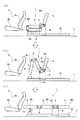
図1および図2は、本発明の第1の実施形態を示しており、図1は、本実施形態にかかる車両用シートの概略構成を示す側面図、図2は、本実施形態にかかる車両用シートによるシートアレンジを例示する側面図である。 1 and 2 show a first embodiment of the present invention, FIG. 1 is a side view showing a schematic configuration of a vehicle seat according to the present embodiment, and FIG. 2 shows a vehicle according to the present embodiment. It is a side view which illustrates the seat arrangement by the sheet for use.
図1および図2は、本実施形態にかかる車両用シートを2列シートの車両に適用した例を示しており、この車両では、フロント側の1列目には二つのシート要素2a,2bを有するシート2が配置され、リア側の2列目には三つのシート要素3,4,8を有するシート1が配置されている。
1 and 2 show an example in which the vehicle seat according to this embodiment is applied to a two-row seat vehicle. In this vehicle, two
シート1では、上側シートクッション3とシートバック4とは、上側シートクッション3の後端部の両側端に設けられたヒンジ5を介して互いに接続されている。そして、シートバック4は、フロア7に対して略平行となる位置まで後傾させることができるようにしてある一方、上側シートクッション3は、その前側を跳ね上げる方向に回動させることができるようにしてある。また、ヒンジ5は、シート1の台座となるシートスライダ6に支持されている。
In the seat 1, the
通常使用時(図1の(a))には、上側シートクッション3と下側シートクッション8とは積層されている。また、これら上側シートクッション3と下側シートクッション8とは、前端部の両側端に設けられたヒンジ9を介して互いに接続されている。
During normal use (FIG. 1A), the
さらに、フロア7上には、前後方向に伸びる2本の平行なレール10が設けられており、シートスライダ6は、このレール10に沿って進退自在に案内される。
Further, two
したがって、図1の(b)に示すように、上側シートクッション3の前側を上方に跳ね上げ、下側シートクッション8を下側から前方側に回動させて上側シートクッション3の前方に進出させる一方、シートバック4を後傾させ、さらにシートスライダ6をリア側に移動させることにより、1列目のシート2のリア側に、ほぼ平坦なシート面(所謂フルフラット面)20を形成することができる(図1の(c))。この場合、シート面20は、フロント側から、下側シートクッション8の下面8L、上側シートクッション3の上面(表面)3U、およびシートバック4の表面(フロント側の面)4Sによって形成されることになる。なお、下側シートクッション8には、収納自在な脚部11が設けられており、この脚部11を下方に立設したときにシート面20とフロア7とが略平行となるようにしてある。
Accordingly, as shown in FIG. 1B, the front side of the
以上のように、本実施形態によれば、三つのシート要素3,4,8を有する2列目のシート1により、広い平坦なシート面を得ることができる。さらに、図示しないが、一列目のシート2のシートバック2aを後傾させて平坦面を形成し、シート2による平坦面にシート面20が縦続するようにシート1を移動させれば、一層広い平坦面を得ることができる。
As described above, according to the present embodiment, a wide flat sheet surface can be obtained by the second row of sheets 1 having the three
また、本実施形態によれば、上述したように、通常使用時には、上側シートクッション3と下側シートクッション8とを折り畳んで収納できるようにしたため、シート2とほぼ同じ容積で構成することができるという利点がある。
Further, according to the present embodiment, as described above, the
さらに、本実施形態によれば、ヒンジ5,9を支点として各シート要素3,4,8を適宜に回動させることにより、図2に例示するような多彩なシートアレンジを、極めて容易に得ることができる。
Furthermore, according to the present embodiment, various seat arrangements as illustrated in FIG. 2 can be obtained very easily by appropriately rotating the
例えば、図2の(a)は、上側シートクッション3および下側シートクッション8のみを展開し、シートバック4を傾動させない場合のシートアレンジを示している。このシートアレンジによれば、シートバック4により、荷物や乗員がリア側に飛び出すのを抑制することができるという利点がある。
For example, FIG. 2A shows a seat arrangement when only the
図2の(b)は、シートバック4、上側シートクッション3および下側シートクッション8をそれぞれフロア7に対して適宜に傾斜させ、凸凹のシート面が形成されるようにしたシートアレンジを示している。このシートアレンジによれば、最もフロント側にある下側シートクッション8を乗員の足乗せ台(オットマン)として用いることができる。
FIG. 2 (b) shows a seat arrangement in which the seat back 4, the
図2の(c)は、各シート要素3,4,8がフロア7に対して直交する位置まで回動させつつ折り畳むとともに、シートスライダ6を移動させてフロント側に寄せたシートアレンジを示している。このシートアレンジによれば、シート1を、急停止時等にリア側に搭載した荷物が前方に飛び出すのを抑制する壁として用いることができる。
FIG. 2C shows a seat arrangement in which the
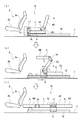
図3は、本発明の第2実施形態にかかる車両用シートの概略構成を示す側面図である。 FIG. 3 is a side view showing a schematic configuration of the vehicle seat according to the second embodiment of the present invention.
図3は、本実施形態にかかる車両用シートを2列シートの車両に適用した例を示しており、この車両では、フロント側の1列目には二つのシート要素を有するシート2が配置され、リア側の2列目には三つのシート要素3,4,8を有するシート12が配置されている。
FIG. 3 shows an example in which the vehicle seat according to this embodiment is applied to a two-row seat vehicle. In this vehicle, a
シート12では、シートバック4と下側シートクッション8とは、下側シートクッション8の後端部の両側端に設けられたヒンジ13を介して互いに接続されている。このヒンジ13は、シート12の台座となるシートスライダ6に支持されている。そして、この実施形態でも、シートバック4はフロア7に対して略平行となる位置まで後傾させることができるようにしてある。
In the
このシート12でも、上側シートクッション3と下側シートクッション8とは、前端部の両側端に設けられたヒンジ14を介して互いに接続されており、この上側シートクッション3は、図3の(b)に示すように、ヒンジ14を支点として後側を跳ね上げて上側から回動させて下側シートクッション8の前方に進出させ、フロア7に対して略平行となる位置で固定できるようにしてある。
Also in this
したがって、図3の(c)に示すような、ほぼ平坦なシート面(所謂フルフラット面)21を形成することができる。この場合、シート面21は、フロント側から、上側シートクッション3の下面(裏面)3L、下側シートクッション8の上面8U、およびシートバック4の表面4Sによって形成されることになる。
Therefore, a substantially flat sheet surface (so-called full flat surface) 21 as shown in FIG. 3C can be formed. In this case, the seat surface 21 is formed from the front side by the lower surface (back surface) 3L of the
すなわち、本実施形態によっても、三つのシート要素3,4,8を有する2列目のシート12により、広い平坦なシート面を得ることができる。
That is, also in this embodiment, a wide flat sheet surface can be obtained by the second row of
そして、本実施形態でも、通常使用時には、上側シートクッション3と下側シートクッション8とを折り畳んで収納できるようにしたため、シート2とほぼ同じ容積で構成することができるという利点がある。
In the present embodiment, the
また、本実施形態でも、図示しないが、ヒンジ13,14を支点として各シート要素3,4,8を適宜に回動させることにより、多彩なシートアレンジを極めて容易に得ることができる。
Also in this embodiment, although not shown, various seat arrangements can be obtained very easily by appropriately rotating the
図4は、本発明の第3実施形態にかかる車両用シートの概略構成を示す側面図である。 FIG. 4 is a side view showing a schematic configuration of the vehicle seat according to the third embodiment of the present invention.
図4は、本実施形態にかかる車両用シートを2列シートの車両に適用した例を示しており、この車両では、フロント側の1列目には二つのシート要素2a,2bを有するシート2が配置され、リア側の2列目には三つのシート要素3,4,8を有するシート15が配置されている。
FIG. 4 shows an example in which the vehicle seat according to the present embodiment is applied to a two-row seat vehicle. In this vehicle, a
シート15では、上側シートクッション3と下側シートクッション8とは、前端部の両側端に設けられたヒンジ17を介して互いに接続されており、この上側シートクッション3は、図4の(b)に示すように、ヒンジ17を支点として後側を跳ね上げて上側から回動させて下側シートクッション8の前方に進出させ、フロア7に対して略平行となる位置で固定できるようにしてある。
In the
さらに、このシート15では、上側シートクッション3とシートバック4とが、上側シートクッション3の後端部の両側端に設けられたヒンジ16を介して互いに接続されており、このシートバック4は、図4の(b)に示すように、ヒンジ16を支点として上側から回動させて下側シートクッション8の前方に進出させ、フロア7に対して略平行となる位置で固定できるようにしてある。
Further, in the
したがって、図4の(c)に示すような、ほぼ平坦なシート面(所謂フルフラット面)22を形成することができる。この場合、シート面22は、フロント側から、シートバック4の裏面4B、上側シートクッション3の下面(裏面)3L、および下側シートクッション8の上面8Uによって形成されることになる。これらの面4B,3L,8Uはいずれも通常使用時には乗員と接触しない面である。したがって、これらの面4B,3L,8Uには、乗員の体をサポートしたり座り心地を良くするための凹凸を形成する必要が無く、本実施形態では、こうした凹凸の無いフラットなシート面22を形成することができるという利点がある。
Therefore, a substantially flat sheet surface (so-called full flat surface) 22 as shown in FIG. 4C can be formed. In this case, the
本実施形態によっても、三つのシート要素3,4,8を有する2列目のシート15により、広い平坦なシート面を得ることができる。
Also in this embodiment, a wide flat sheet surface can be obtained by the second row of
そして、上述したように、本実施形態でも、上側シートクッション3と下側シートクッション8とを折り畳んで収納するようにしたため、シート2とほぼ同じ容積で構成することができるという利点がある。
As described above, the present embodiment also has an advantage that the
また、本実施形態によっても、図示しないが、ヒンジ16,17を支点として各シート要素3,4,8を適宜に回動させることにより、多彩なシートアレンジを極めて容易に得ることができる。
Also, according to the present embodiment, although not shown, various seat arrangements can be obtained very easily by appropriately rotating the
以上、本発明の好適な実施形態について説明したが、本発明は上記実施形態に限定されるものではなく、要旨を逸脱しない範囲で上記実施形態に種々の改変を施すことができる。例えば、上記実施形態では、本発明にかかる車両用シートを2列シートの車両の2列目に適用した場合について説明したが、より多列シートの車両に適用することができるのは勿論であるし、1列目に適用してもよい。また、分割シートに適用することも勿論可能である。 The preferred embodiments of the present invention have been described above, but the present invention is not limited to the above embodiments, and various modifications can be made to the above embodiments without departing from the scope of the invention. For example, in the above embodiment, the case where the vehicle seat according to the present invention is applied to the second row of the two-row seat vehicle has been described. And it may be applied to the first column. Of course, it can also be applied to divided sheets.
1,12,15 シート(車両用シート)
3 上側シートクッション
4 シートバック
5,9,13,14,16,17 ヒンジ
6 シートスライダ
7 フロア
8 下側シートクッション
10 レール
1,12,15 seat (vehicle seat)
3
Claims (7)
上下に積層され前端部でヒンジを介して相互に接続される上側シートクッションと下側シートクッションとを備え、該ヒンジを支点として該上側シートクッションと下側シートクッションとを展開することにより、下側シートクッションを露出自在としたことを特徴とする車両用シート。 In a vehicle seat comprising a seat cushion and a seat back,
An upper seat cushion and a lower seat cushion, which are stacked one above the other and are connected to each other via a hinge at the front end, are developed by deploying the upper seat cushion and the lower seat cushion with the hinge as a fulcrum. A vehicle seat characterized in that the side seat cushion is freely exposed.
Priority Applications (1)
| Application Number | Priority Date | Filing Date | Title |
|---|---|---|---|
| JP2004120256A JP2005297897A (en) | 2004-04-15 | 2004-04-15 | Vehicle seat |
Applications Claiming Priority (1)
| Application Number | Priority Date | Filing Date | Title |
|---|---|---|---|
| JP2004120256A JP2005297897A (en) | 2004-04-15 | 2004-04-15 | Vehicle seat |
Publications (1)
| Publication Number | Publication Date |
|---|---|
| JP2005297897A true JP2005297897A (en) | 2005-10-27 |
Family
ID=35329952
Family Applications (1)
| Application Number | Title | Priority Date | Filing Date |
|---|---|---|---|
| JP2004120256A Pending JP2005297897A (en) | 2004-04-15 | 2004-04-15 | Vehicle seat |
Country Status (1)
| Country | Link |
|---|---|
| JP (1) | JP2005297897A (en) |
Cited By (7)
| Publication number | Priority date | Publication date | Assignee | Title |
|---|---|---|---|---|
| JP2008062676A (en) * | 2006-09-04 | 2008-03-21 | Shiroki Corp | Vehicle seat and railway vehicle |
| JP2016500610A (en) * | 2012-10-26 | 2016-01-14 | ゾディアック シーツ フランス | Aircraft seat configuration, arrangement system and arrangement method |
| KR102114456B1 (en) * | 2020-01-22 | 2020-05-22 | 허득범 | Car seat can be transformed into a bed |
| US11772517B2 (en) | 2020-11-09 | 2023-10-03 | Ford Global Technologies, Llc | Vehicular system capable of adjusting a passenger compartment from a child seat arrangement to a second arrangement |
| US11904732B2 (en) | 2020-11-09 | 2024-02-20 | Ford Global Technologies, Llc | Vehicular system capable of adjusting a passenger compartment from a first arrangement to a child care arrangement |
| US12077068B2 (en) | 2020-11-09 | 2024-09-03 | Ford Global Technologies, Llc | Authorization-based adjustment of passenger compartment arrangement |
| US12257932B2 (en) | 2020-11-09 | 2025-03-25 | Ford Global Technologies, Llc | Exterior imager utilized in adjusting a passenger compartment arrangement |
-
2004
- 2004-04-15 JP JP2004120256A patent/JP2005297897A/en active Pending
Cited By (7)
| Publication number | Priority date | Publication date | Assignee | Title |
|---|---|---|---|---|
| JP2008062676A (en) * | 2006-09-04 | 2008-03-21 | Shiroki Corp | Vehicle seat and railway vehicle |
| JP2016500610A (en) * | 2012-10-26 | 2016-01-14 | ゾディアック シーツ フランス | Aircraft seat configuration, arrangement system and arrangement method |
| KR102114456B1 (en) * | 2020-01-22 | 2020-05-22 | 허득범 | Car seat can be transformed into a bed |
| US11772517B2 (en) | 2020-11-09 | 2023-10-03 | Ford Global Technologies, Llc | Vehicular system capable of adjusting a passenger compartment from a child seat arrangement to a second arrangement |
| US11904732B2 (en) | 2020-11-09 | 2024-02-20 | Ford Global Technologies, Llc | Vehicular system capable of adjusting a passenger compartment from a first arrangement to a child care arrangement |
| US12077068B2 (en) | 2020-11-09 | 2024-09-03 | Ford Global Technologies, Llc | Authorization-based adjustment of passenger compartment arrangement |
| US12257932B2 (en) | 2020-11-09 | 2025-03-25 | Ford Global Technologies, Llc | Exterior imager utilized in adjusting a passenger compartment arrangement |
Similar Documents
| Publication | Publication Date | Title |
|---|---|---|
| US7341302B2 (en) | Seating arrangement for a vehicle | |
| JP2004106739A (en) | Vehicle seat arrangement structure | |
| JP4717193B2 (en) | Car seat structure | |
| US7850246B2 (en) | Shingled thin seat construction for vehicle | |
| JP2004131044A (en) | Front seat assembly for automobile | |
| JP2005297897A (en) | Vehicle seat | |
| JP2004155421A (en) | Layout of backseat of automobile that includes folding backrest provided for headrest, and vehicle equipped with this seat | |
| CN107336641A (en) | It is vehicle seat used | |
| JP2003276482A (en) | Vehicular rear seat | |
| JP4395684B2 (en) | Headrest mounting structure | |
| JP7186250B2 (en) | seat | |
| JP7073147B2 (en) | Vehicle seat | |
| JPH07172223A (en) | Vehicular multi-purpose seat | |
| JP3870805B2 (en) | Vehicle seat device | |
| JPH10264698A (en) | Rear seat for vehicle | |
| JP4114026B2 (en) | Sheet folding structure | |
| JP2005297632A (en) | Vehicle seat structure | |
| JP4762584B2 (en) | Vehicle seat device | |
| JP2007168609A (en) | Vehicle seat structure | |
| JP2019151196A (en) | Vehicle seat structure | |
| JP2008279893A (en) | Vehicle seat device | |
| JP4561161B2 (en) | Vehicle seat device | |
| JPH10226253A (en) | Vehicle seat | |
| JP2005075075A (en) | Vehicle seat | |
| JP3261980B2 (en) | Vehicle seat |