JP2005297041A - Pipe forming method and pipe forming apparatus - Google Patents
Pipe forming method and pipe forming apparatus Download PDFInfo
- Publication number
- JP2005297041A JP2005297041A JP2004119822A JP2004119822A JP2005297041A JP 2005297041 A JP2005297041 A JP 2005297041A JP 2004119822 A JP2004119822 A JP 2004119822A JP 2004119822 A JP2004119822 A JP 2004119822A JP 2005297041 A JP2005297041 A JP 2005297041A
- Authority
- JP
- Japan
- Prior art keywords
- metal pipe
- sectional shape
- cross
- processing roller
- diameter
- Prior art date
- Legal status (The legal status is an assumption and is not a legal conclusion. Google has not performed a legal analysis and makes no representation as to the accuracy of the status listed.)
- Pending
Links
Images
Landscapes
- Shaping Metal By Deep-Drawing, Or The Like (AREA)
Abstract
Description
本発明は、スピニング加工による金属パイプの成形に関し、特に楕円形などの非軸対称形状の断面を有する金属パイプの端部を円形断面などに縮径するパイプ成形方法及びパイプ成形装置に関するものである。 The present invention relates to forming a metal pipe by spinning, and more particularly to a pipe forming method and a pipe forming apparatus for reducing the diameter of an end of a metal pipe having a non-axisymmetric cross section such as an ellipse to a circular cross section. .
従来より、金属パイプの成形方法が種々提案されている。例えば、自動車の触媒コンバータや消音器用の金属容器本体として、搭載スペース等を考慮して断面が楕円形など扁平な非軸対称形状のパイプがしばしば用いられる。これらの端部は排気管等と接続するために小径の円形断面としなくてはならない。従来このような容器は、例えば楕円形断面のパイプ部分と端部となる部材、あるいは容器を縦に2分割した形状の部材を別々に成形し、これらを溶接することで製作している。しかしながら、上記の方法で容器を製作するには各部材の成形や溶接などの作業に時間がかかり作業性が劣るという問題があった。
円形断面の金属パイプを縮径する際には、回転する金属パイプに加工ローラを押し付けて成形するスピニング加工を用いることができる。しかし、従来のスピニング加工を用いて上記のような非軸対称形状の金属パイプの縮径を行うと、加工ローラが描く軌跡と金属パイプの断面形状が一致しないため、加工ローラと金属パイプの接触が断続的となり、その結果、製品に歪みが生じたり、本体のパイプ部分と両端の縮径部との境界が滑らかでなくなる。
非軸対称形状、特に楕円形断面の金属パイプ端部の縮径をスピニング加工によって行うための方法として、特開2001−286955号では、加工ローラを金属パイプの周りに公転させながら、金属パイプの断面形状に合わせて公転半径を変動させることにより加工ローラと金属パイプの接触を保つ方法が考案されている。
また、特開2002−66665号および特開2004−1023号では、まず金属パイプ端部をプレス加工などにより円形断面に変形し、その後にスピニング加工により変形部分の縮径を行う方法が考案されている。
When reducing the diameter of a metal pipe having a circular cross section, a spinning process in which a processing roller is pressed against a rotating metal pipe to form can be used. However, when the diameter of a non-axisymmetric metal pipe as described above is reduced using conventional spinning, the locus drawn by the processing roller and the cross-sectional shape of the metal pipe do not match, so the contact between the processing roller and the metal pipe As a result, the product is distorted, and the boundary between the pipe portion of the main body and the reduced diameter portions at both ends is not smooth.
As a method for reducing the diameter of an end portion of a metal pipe having a non-axisymmetric shape, particularly an elliptical cross section by spinning, Japanese Patent Application Laid-Open No. 2001-286955 discloses a method of rotating a metal roller around a metal pipe while rotating the metal pipe. A method has been devised for maintaining the contact between the processing roller and the metal pipe by varying the revolution radius in accordance with the cross-sectional shape.
Japanese Patent Laid-Open No. 2002-66665 and Japanese Patent Laid-Open No. 2004-1023 have devised a method in which a metal pipe end is first deformed into a circular cross section by pressing or the like, and then the diameter of the deformed portion is reduced by spinning. Yes.
しかしながら、前掲の特開2001−286955号の方法では、加工ローラをその公転半径を変動させる複雑な機構とともに金属パイプの周りに公転させる必要があるため、公転の回転数を上げることができず加工時間が長くなるという問題があった。また、前掲の特開2002−66665号および特開2004−1023号の方法では、スピニング加工の前工程として、プレス加工による金属パイプの変形工程が余分に必要となっていた。 However, in the method disclosed in Japanese Patent Laid-Open No. 2001-286955, it is necessary to revolve the processing roller around the metal pipe together with a complicated mechanism for changing the revolving radius of the processing roller. There was a problem that time became long. Moreover, in the method of the above-mentioned Unexamined-Japanese-Patent No. 2002-66665 and Unexamined-Japanese-Patent No. 2004-1023, the deformation | transformation process of the metal pipe by press work was needed as a pre-process of spinning process.
この発明は、上記に鑑み提案されたもので、非軸対称形状の金属パイプ端部を関数制御された複数の加工ローラを使用したスピニング加工により、順次滑らかに短時間で縮径するパイプ成形方法およびパイプ成形装置を提供することを目的とする。 The present invention has been proposed in view of the above, and a pipe forming method for smoothly reducing the diameter of a non-axisymmetric metal pipe end portion in a short time sequentially by spinning using a plurality of function-controlled processing rollers. And it aims at providing a pipe forming apparatus.
上記目的を達成する為に、本発明のパイプ成形方法は、断面が楕円形等の非軸対称形状の金属パイプの端部を縮径するパイプ成形方法であって、前記金属パイプを回転角センサ付きモータによって駆動される主軸に取り付けて回転させる工程と、前記金属パイプの外周に配した主軸方向および半径方向に駆動可能な複数の加工ローラを前記主軸の回転角に同期して半径方向に進退させる工程と、前記加工ローラと前記金属パイプとの接触点が予め設定した断面形状の軌道に接するように制御し、前記加工ローラの主軸方向送りに同期して前記軌道の形状を滑らかに変化させる工程を順次繰り返し、前記金属パイプを所望の断面形状まで縮径することを特徴としている。 In order to achieve the above object, the pipe forming method of the present invention is a pipe forming method for reducing the diameter of an end portion of a metal pipe having a non-axisymmetric shape such as an ellipse in cross section. Attaching to the main shaft driven by the attached motor and rotating it, and a plurality of processing rollers arranged on the outer periphery of the metal pipe that can be driven in the main shaft direction and the radial direction are advanced and retracted in the radial direction in synchronization with the rotation angle of the main shaft. And the contact point between the processing roller and the metal pipe is controlled so as to contact a predetermined cross-sectional shape of the track, and the shape of the track is smoothly changed in synchronism with the spindle feed of the processing roller. The steps are sequentially repeated to reduce the diameter of the metal pipe to a desired cross-sectional shape.
また、請求項2に記載の発明において、前記金属パイプの初期断面形状と目標とする縮径後の断面形状から、前記加工ローラの主軸方向送り変位に基づく補間計算により、縮径部テーパ部分の成形における前記加工ローラの半径方向送り変位を順次決定することを特徴とする。 Further, in the invention according to claim 2, from the initial cross-sectional shape of the metal pipe and the target cross-sectional shape after the diameter reduction, an interpolation calculation based on a feed displacement in the main shaft direction of the processing roller performs an interpolation calculation of the reduced diameter portion taper portion. A radial feed displacement of the processing roller in molding is sequentially determined.
また、請求項3に記載の発明において、前記断面が楕円形など非軸対称形状の金属パイプの端部を縮径するパイプ成形装置であって、前記金属パイプを把持するためのチャックを備えた主軸モータと、前記主軸モータに取り付けられた回転角センサと、前記チャックに装着された金属パイプを加工するための加工ローラと、前記加工ローラを金属パイプの主軸方向および半径方向に駆動可能な駆動手段と、前記駆動手段を制御する制御手段とを備え、前記加工ローラと前記金属パイプとの接触点が予め設定した断面形状になるように前記主軸モータの回転角に同期して前記加工ローラを半径方向に進退させながら、前記加工ローラの主軸方向送りに同期して前記設定断面形状を変化させる工程を順次繰り返し、前記金属パイプを所望の断面形状まで滑らかに縮径することを特徴とする。 The invention according to claim 3 is a pipe forming apparatus for reducing the diameter of an end portion of a metal pipe having a non-axisymmetric shape such as an ellipse in cross section, comprising a chuck for gripping the metal pipe. A main shaft motor, a rotation angle sensor attached to the main shaft motor, a processing roller for processing the metal pipe attached to the chuck, and a drive capable of driving the processing roller in the main shaft direction and the radial direction of the metal pipe And a control means for controlling the driving means, and the processing roller is synchronized with a rotation angle of the spindle motor so that a contact point between the processing roller and the metal pipe has a preset cross-sectional shape. The process of changing the set cross-sectional shape in order to synchronize with the feeding of the processing roller in the main axis direction while advancing and retreating in the radial direction is sequentially repeated, so that the metal pipe has a desired cross-sectional shape Characterized in that it smoothly reduced in diameter to.
また、請求項4に記載の発明において、前記制御手段は、素材である前記金属パイプの初期断面形状と目標とする縮径後の断面形状から、前記加工ローラの主軸方向送り変位に基づく補間計算により、縮径部テーパ部分の成形における前記加工ローラの半径方向送り変位を決定することを特徴とする。 Further, in the invention according to claim 4, the control means performs an interpolation calculation based on a feed displacement in the main shaft direction of the processing roller from an initial cross-sectional shape of the metal pipe as a material and a target cross-sectional shape after the diameter reduction. To determine a radial feed displacement of the processing roller in forming the tapered portion of the reduced diameter portion.
この発明は上記した構成からなるので、以下に説明するような効果を奏することができる。 Since this invention consists of an above-described structure, there can exist an effect which is demonstrated below.
請求項1に記載の発明では、断面が楕円形等の非軸対称形状の金属パイプの端部を縮径するパイプ成形方法であって、前記金属パイプを回転角センサ付きモータによって駆動される主軸に取り付けて回転させる工程と、前記金属パイプの外周に配した主軸方向および半径方向に駆動可能な複数の加工ローラを前記主軸の回転角に同期して半径方向に進退させる工程と、前記加工ローラと前記金属パイプとの接触点が予め設定した断面形状の軌道に接するように制御し、前記加工ローラの主軸方向送りに同期して前記軌道の形状を滑らかに変化させる工程を順次繰り返し、前記金属パイプを所望の断面形状まで縮径するので、成形後の断面形状を滑らかに変化でき、製品に歪みを与えることなく縮径することができる。
The invention according to
請求項2に記載の発明では、前記金属パイプの初期断面形状と目標とする縮径後の断面形状から、前記加工ローラの主軸方向送り変位に基づく補間計算により、縮径部テーパ部分の成形における前記加工ローラの半径方向送り変位を順次決定するので、三次元データを用いることなく、簡易な補間計算により加工ローラの運動を制御して滑らかに金属パイプ端部を縮径することができる。 In the invention according to claim 2, in the formation of the tapered portion of the reduced diameter portion by interpolation calculation based on the main-axis direction feed displacement of the processing roller from the initial sectional shape of the metal pipe and the target sectional shape after the diameter reduction. Since the radial feed displacement of the processing roller is sequentially determined, the metal pipe end portion can be smoothly reduced in diameter by controlling the motion of the processing roller by simple interpolation calculation without using three-dimensional data.
請求項3に記載の発明では、前記断面が楕円形など非軸対称形状の金属パイプの端部を縮径するパイプ成形装置であって、前記金属パイプを把持するためのチャックを備えた主軸モータと、前記主軸モータに取り付けられた回転角センサと、前記チャックに装着された金属パイプを加工するための加工ローラと、前記加工ローラを金属パイプの主軸方向および半径方向に駆動可能な駆動手段と、前記駆動手段を制御する制御手段とを備え、前記加工ローラと前記金属パイプとの接触点が予め設定した断面形状になるように前記主軸モータの回転角に同期して前記加工ローラを半径方向に進退させながら、前記加工ローラの主軸方向送りに同期して前記設定断面形状を変化させる工程を順次繰り返し、前記金属パイプを所望の断面形状まで滑らかに縮径するので、成形後の断面形状を滑らかに変化でき、製品に歪みを与えることなく縮径することができる。 According to a third aspect of the present invention, there is provided a pipe forming apparatus for reducing the diameter of an end portion of a metal pipe having a non-axisymmetric shape such as an ellipse in cross section, and a spindle motor including a chuck for gripping the metal pipe A rotation angle sensor attached to the main shaft motor, a processing roller for processing the metal pipe mounted on the chuck, and a driving means capable of driving the processing roller in the main axis direction and the radial direction of the metal pipe. And a control means for controlling the drive means, and the radial direction of the machining roller is synchronized with the rotation angle of the spindle motor so that the contact point between the machining roller and the metal pipe has a preset cross-sectional shape. The step of changing the set cross-sectional shape is sequentially repeated in synchronization with the feed of the processing roller in the main axis direction, and the metal pipe is slid to a desired cross-sectional shape. Since reduced in diameter, the cross-sectional shape after molding smoothly be changed, it can be reduced in diameter without distorting the product.
請求項4に記載の発明では、前記制御手段は、素材である前記金属パイプの初期断面形状と目標とする縮径後の断面形状から、前記加工ローラの主軸方向送り変位に基づく補間計算により、縮径部テーパ部分の成形における前記加工ローラの半径方向送り変位を決定するので、三次元データを用いることなく、簡易な補間計算により加工ローラの運動を制御して滑らかに金属パイプ端部を縮径することができる。 In the invention according to claim 4, the control means, from the initial cross-sectional shape of the metal pipe that is a material and the target cross-sectional shape after the diameter reduction, by interpolation calculation based on the main-axis direction feed displacement of the processing roller, Since the radial feed displacement of the processing roller in forming the tapered portion of the reduced diameter portion is determined, the end of the metal pipe is smoothly contracted by controlling the motion of the processing roller by simple interpolation calculation without using three-dimensional data. Can be calibrated.
非軸対称のパイプを歪みを生じることなく、滑らかに縮径するという目的を関数制御された複数の加工ローラを使用したスピニング加工により、順次短時間で実現することができる。 The objective of smoothly reducing the diameter of a non-axisymmetric pipe without causing distortion can be realized in a short time by spinning using a plurality of function-controlled processing rollers.
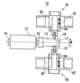
以下、本発明のパイプ成形方法を実施するためのパイプ成形装置の一実施例について図面を参照して説明する。図1は、本発明に係るパイプ成形装置の一例を示す概略平面図である。ここで、パイプ成形装置10は、断面が楕円形など非軸対称形状の金属パイプ11の端部を縮径するものであって、金属パイプ11を把持するためのチャック12を備えた主軸モータ13と、前記主軸モータ13に取り付けられた回転角センサ14と、前記チャック12に装着された金属パイプ11を加工するための加工ローラ15と、前記加工ローラ15を金属パイプ11の主軸方向および半径方向に駆動可能な駆動手段16と、前記駆動手段16を制御する制御手段17とを備えている。
Hereinafter, an embodiment of a pipe forming apparatus for carrying out the pipe forming method of the present invention will be described with reference to the drawings. FIG. 1 is a schematic plan view showing an example of a pipe forming apparatus according to the present invention. Here, the
金属パイプ11は、例えば、図2、3に示すように断面が楕円形状をしており、チャック12に装着固定される。主軸モータ13の後端には、回転角センサ14が取り付けられており、主軸回転角θを実測することができる。また、駆動手段16は、それぞれ直交配置された直動テーブル18と直動テーブル19とから構成されている。駆動手段16は、金属パイプ11の両側に配置されている。直動テーブル18、18’は、ボールねじなどで駆動され、それぞれ主軸半径方向に前進あるいは後退するよう構成されている。また、直動テーブル18、18’はそれぞれ直動テーブル19、19’によって主軸方向に前進あるいは後退する。直動テーブル19、19’は、図1に示すように独立となっていても良く、または一体的に構成された直動テーブルで直動テーブル18、18’を駆動しても良い。各直動テーブルは送り量を検出するエンコーダなどの変位センサを備えるものとする。
For example, as shown in FIGS. 2 and 3, the
次に、以上のように構成されたパイプ成形装置の動作について説明する。断面が楕円形など非軸対称形状の金属パイプ11は、成形加工の対象として、チャック12により回転角センサ14を有する主軸モータ13に固定されて回転する。加工ローラ15、15’はボールねじなどで駆動される直動テーブル18、18’によってそれぞれ主軸半径方向に駆動される。また、直動テーブル18、18’は、それぞれ直動テーブル19、19’によって主軸方向に前進あるいは後退する。直動テーブル19、19’は、図1に示すように独立となっていても、または一体となった直動テーブルで直動テーブル18、18’を動かしても良い。各直動テーブルは、送り量を検出するエンコーダなどの変位センサを備えるものとする。
Next, the operation of the pipe forming apparatus configured as described above will be described. A
加工ローラ15、15’を主軸モータ13の回転角に同期して直動テーブル18、18’により半径方向に前進または後退させ、加工ローラ15、15’と金属パイプ11との接触点が目標とする断面形状の軌道に接するように制御する。一方、直動テーブル19、19’により直動テーブル18、18’を主軸と平行に金属パイプ11の先端に向かって送る。直動テーブル19、19’の送り変位に同期して前記軌道の形状を滑らかに変化させ、金属パイプ11を所望の形状11’まで縮径する。
The
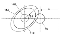
図2は、金属パイプ11と加工ローラ15の接触の様子を主軸に直交する断面図で示したものである。金属パイプ11と加工ローラ15の接触点の軌跡が図2に示すように目標とする断面形状11dとなるよう加工ローラ15の半径方向の送り変位Xを決定する。そのとき、送り変位Xは主軸の回転角θの関数X(θ)として表わされる。目標とする断面形状11dは、素材の金属パイプの断面形状11Aからパイプ先端の断面形状11Bまで、加工ローラ15の主軸方向の送り変位Zの増加に従って徐々に変化する。断面形状が11Aのときの送り変位Xの関数をXA(θ)、断面形状が11Bのときの送り変位Xの関数をXB(θ)として表わす。
FIG. 2 shows a state of contact between the
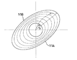
図3は、本発明のパイプ成形装置における各半径方向に於ける縮径状態を示す説明図である。本実施例では、長径rnを順次縮径してr0とする。 FIG. 3 is an explanatory view showing a reduced diameter state in each radial direction in the pipe forming apparatus of the present invention. In this embodiment, the major axis rn is sequentially reduced to r0.
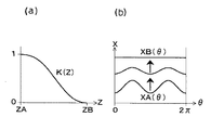
図4は、加工ローラの半径方向送り変位Xの補間計算の方法を示す。成形開始点における主軸方向の送り変位ZをZA、金属パイプ先端における主軸方向の送り変位ZをZBとする。図4(a)のような補間のための関数K(Z)を考える。K(Z)は、
K(ZA)=1,K(ZB)=0
を満たす滑らかな単調減少関数とする。加工ローラの主軸方向の送り変位がZ、主軸の回転角がθのとき、加工ローラの半径方向の送り変位Xを
X=K(Z)XA(θ)+{1−K(Z)}XB(θ)・・・・(1)
によって計算する。このとき、成形開始点(Z=ZA)においてはX=XA(θ)となり、また金属パイプ先端(Z=ZB)においてはX=XB(θ)となる。その中間においては、図4(b)のように半径方向送り変位Xの変動はK(Z)に従って滑らかに変化する。これにより金属パイプ端部を成形開始点から先端まで滑らかに縮径することができる。成形部分の主軸を含む断面の形状は、K(Z)を伸縮したものと相似形となる。なお、加工ローラ15’の半径方向変位に関しても、全く同様に計算することができる。
FIG. 4 shows a method of interpolation calculation of the radial feed displacement X of the processing roller. The feed displacement Z in the main shaft direction at the forming start point is ZA, and the feed displacement Z in the main shaft direction at the tip of the metal pipe is ZB. Consider a function K (Z) for interpolation as shown in FIG. K (Z) is
K (ZA) = 1, K (ZB) = 0
A smooth monotonically decreasing function that satisfies When the feed displacement in the main shaft direction of the processing roller is Z and the rotation angle of the main shaft is θ, the feed displacement X in the radial direction of the processing roller is X = K (Z) XA (θ) + {1−K (Z)} XB (Θ) (1)
Calculate by At this time, X = XA (θ) at the forming start point (Z = ZA), and X = XB (θ) at the metal pipe tip (Z = ZB). In the middle, as shown in FIG. 4B, the variation of the radial feed displacement X changes smoothly according to K (Z). Thereby, a metal pipe end part can be smoothly diameter-reduced from a shaping | molding start point to a front-end | tip. The shape of the cross section including the main axis of the molded part is similar to that obtained by expanding and contracting K (Z). The radial displacement of the
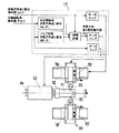
図5は、本発明による金属パイプの成形を行うための制御手段の構成を示す。制御手段17には、加工ローラ15の主軸方向送り変位指令値Zd(t)および主軸回転角指令値θd(t)が与えられる。Zd(t)、θd(t)は、時間tの経過に従って増加する。主軸回転角指令値θd(t)は、サーボアンプに入力され、主軸モータ13を駆動して金属パイプ11を回転させる。主軸方向送り変位指令値Zd(t)もサーボアンプに入力され、直動テーブル19を駆動して直動テーブル18および加工ローラ15を主軸と平行に金属パイプ11の先端に向かって送る。
FIG. 5 shows the configuration of the control means for forming the metal pipe according to the present invention. The control means 17 is given a spindle direction feed displacement command value Zd (t) and a spindle rotation angle command value θd (t) of the
また、あらかじめ記憶された加工開始点における加工ローラ15の半径方向送り変位XA(θ)および金属パイプ先端における半径方向送り変位XB(θ)に基づいて、現在の主軸回転角指令値θd(t)に対応するそれぞれの半径方向送り変位XA(θd(t))、XB(θd(t))を求める。これらと現在の主軸方向送り変位指令値Zd(t)から(1)式の補間計算により加工ローラ15の半径方向送り変位指令値Xdを計算する。半径方向の送り変位指令値Xdは、サーボアンプに入力され、直動テーブル18を駆動して加工ローラ15を半径方向に前進または後退させる。図5では、加工ローラ15’に関する制御手段の構成は省略したが、上記と同様に直動テーブル18’、19’を駆動する制御手段を構成することができる。
Further, the current spindle rotation angle command value θd (t) based on the radial feed displacement XA (θ) of the
なお、図5では補間計算に主軸回転角指令値θd(t)を用いたが、その代わりに主軸モータ13の回転角センサ14で計測された主軸回転角θの実測値を用いて補間計算を行うことも可能である。
In FIG. 5, the spindle rotation angle command value θd (t) is used for the interpolation calculation. Instead, the interpolation calculation is performed using the measured value of the spindle rotation angle θ measured by the
なお、以上、本発明に係るパイプ成形方法および装置を実施例に基づいて説明したが、本発明はこのような実施例に限定されることなく、特許請求の範囲に記載した技術的事項の範囲内で種々の実施の態様があることは言うまでもない。 The pipe forming method and apparatus according to the present invention have been described based on the embodiments. However, the present invention is not limited to such embodiments, and the scope of technical matters described in the claims. Needless to say, there are various embodiments.
10 パイプ成形装置
11 金属パイプ
12 チャック
13 主軸モータ
14 回転角センサ
15 加工ローラ
16 駆動手段
17 制御手段
18 直動テーブル
19 直動テーブル
DESCRIPTION OF
Claims (4)
Priority Applications (1)
| Application Number | Priority Date | Filing Date | Title |
|---|---|---|---|
| JP2004119822A JP2005297041A (en) | 2004-04-15 | 2004-04-15 | Pipe forming method and pipe forming apparatus |
Applications Claiming Priority (1)
| Application Number | Priority Date | Filing Date | Title |
|---|---|---|---|
| JP2004119822A JP2005297041A (en) | 2004-04-15 | 2004-04-15 | Pipe forming method and pipe forming apparatus |
Publications (1)
| Publication Number | Publication Date |
|---|---|
| JP2005297041A true JP2005297041A (en) | 2005-10-27 |
Family
ID=35329218
Family Applications (1)
| Application Number | Title | Priority Date | Filing Date |
|---|---|---|---|
| JP2004119822A Pending JP2005297041A (en) | 2004-04-15 | 2004-04-15 | Pipe forming method and pipe forming apparatus |
Country Status (1)
| Country | Link |
|---|---|
| JP (1) | JP2005297041A (en) |
Cited By (15)
| Publication number | Priority date | Publication date | Assignee | Title |
|---|---|---|---|---|
| KR100805126B1 (en) | 2006-05-26 | 2008-02-21 | 엠티 주식회사 | Molding device for aluminum oil separator case |
| CN101823095A (en) * | 2010-03-29 | 2010-09-08 | 新昌县科贸实业有限公司 | Gantry-type rotary pressing machine |
| CN102847710A (en) * | 2012-09-18 | 2013-01-02 | 昆山坤林彩钢板活动房有限公司 | Pipe contracting machine |
| KR101223509B1 (en) * | 2011-04-01 | 2013-01-17 | (주)두합 | Forming method for upper shaft of steering column |
| CN103600002A (en) * | 2013-11-21 | 2014-02-26 | 沧州市螺旋钢管集团有限公司 | Spinning-type tube end expanding device commonly applied to large-diameter steel tubes |
| JP2015213923A (en) * | 2014-05-08 | 2015-12-03 | トヨタ自動車株式会社 | Sub-muffler and sub-muffler manufacturing method |
| CN105215154A (en) * | 2015-11-09 | 2016-01-06 | 扬中市三环电热科技有限公司 | A kind of electric heating tube machine for shrinking |
| CN106040816A (en) * | 2016-07-11 | 2016-10-26 | 长春设备工艺研究所 | Multifunctional rotary extrusion equipment |
| JP2018515341A (en) * | 2015-10-20 | 2018-06-14 | ライフェルト メタル スピニング アーゲーLeifeld Metal Spinning Ag | Molding machine for spinning / flow forming and method for spinning / flow forming |
| CN109482755A (en) * | 2018-11-23 | 2019-03-19 | 西安航天发动机有限公司 | A kind of closing device |
| CN110548797A (en) * | 2019-09-16 | 2019-12-10 | 芜湖西诺普汽车零部件科技有限公司 | Coreless spinning processing method for large-proportion multi-time reducing hollow shaft |
| CN110788629A (en) * | 2019-11-21 | 2020-02-14 | 常州至能自动化设备有限公司 | Automatic production equipment and process method for metal storage device |
| CN112045024A (en) * | 2020-07-02 | 2020-12-08 | 长春理工大学 | Spinning forming method of parts with oval cross sections |
| CN113798381A (en) * | 2021-09-03 | 2021-12-17 | 中材科技(苏州)有限公司 | Spinning forming device and method for aluminum inner container of high-pressure hydrogen cylinder |
| CN114472658A (en) * | 2022-01-27 | 2022-05-13 | 长春理工大学 | Spin forming equipment for thin-wall part with non-circular section |
Citations (2)
| Publication number | Priority date | Publication date | Assignee | Title |
|---|---|---|---|---|
| JP2001286955A (en) * | 2000-04-11 | 2001-10-16 | Sakamoto Industry Co Ltd | Pipe forming method and forming apparatus |
| JP2003181555A (en) * | 2001-12-13 | 2003-07-02 | National Institute Of Advanced Industrial & Technology | Spinning processing method |
-
2004
- 2004-04-15 JP JP2004119822A patent/JP2005297041A/en active Pending
Patent Citations (2)
| Publication number | Priority date | Publication date | Assignee | Title |
|---|---|---|---|---|
| JP2001286955A (en) * | 2000-04-11 | 2001-10-16 | Sakamoto Industry Co Ltd | Pipe forming method and forming apparatus |
| JP2003181555A (en) * | 2001-12-13 | 2003-07-02 | National Institute Of Advanced Industrial & Technology | Spinning processing method |
Cited By (20)
| Publication number | Priority date | Publication date | Assignee | Title |
|---|---|---|---|---|
| KR100805126B1 (en) | 2006-05-26 | 2008-02-21 | 엠티 주식회사 | Molding device for aluminum oil separator case |
| CN101823095A (en) * | 2010-03-29 | 2010-09-08 | 新昌县科贸实业有限公司 | Gantry-type rotary pressing machine |
| CN101823095B (en) * | 2010-03-29 | 2012-05-02 | 新昌县科贸实业有限公司 | Gantry-type rotary pressing machine |
| KR101223509B1 (en) * | 2011-04-01 | 2013-01-17 | (주)두합 | Forming method for upper shaft of steering column |
| CN102847710A (en) * | 2012-09-18 | 2013-01-02 | 昆山坤林彩钢板活动房有限公司 | Pipe contracting machine |
| CN103600002A (en) * | 2013-11-21 | 2014-02-26 | 沧州市螺旋钢管集团有限公司 | Spinning-type tube end expanding device commonly applied to large-diameter steel tubes |
| US9470124B2 (en) | 2014-05-08 | 2016-10-18 | Toyota Jidosha Kabushiki Kaisha | Sub-muffler and manufacturing method of sub-muffler |
| JP2015213923A (en) * | 2014-05-08 | 2015-12-03 | トヨタ自動車株式会社 | Sub-muffler and sub-muffler manufacturing method |
| JP2018515341A (en) * | 2015-10-20 | 2018-06-14 | ライフェルト メタル スピニング アーゲーLeifeld Metal Spinning Ag | Molding machine for spinning / flow forming and method for spinning / flow forming |
| US10888911B2 (en) | 2015-10-20 | 2021-01-12 | Leifeld Metal Spinning Ag | Forming machine for spinning/flow forming and method for spinning/flow forming |
| CN105215154A (en) * | 2015-11-09 | 2016-01-06 | 扬中市三环电热科技有限公司 | A kind of electric heating tube machine for shrinking |
| CN106040816A (en) * | 2016-07-11 | 2016-10-26 | 长春设备工艺研究所 | Multifunctional rotary extrusion equipment |
| CN109482755A (en) * | 2018-11-23 | 2019-03-19 | 西安航天发动机有限公司 | A kind of closing device |
| CN110548797A (en) * | 2019-09-16 | 2019-12-10 | 芜湖西诺普汽车零部件科技有限公司 | Coreless spinning processing method for large-proportion multi-time reducing hollow shaft |
| CN110548797B (en) * | 2019-09-16 | 2020-07-07 | 芜湖西诺普汽车零部件科技有限公司 | Coreless spinning processing method for large-proportion multi-time reducing hollow shaft |
| CN110788629A (en) * | 2019-11-21 | 2020-02-14 | 常州至能自动化设备有限公司 | Automatic production equipment and process method for metal storage device |
| CN112045024A (en) * | 2020-07-02 | 2020-12-08 | 长春理工大学 | Spinning forming method of parts with oval cross sections |
| CN113798381A (en) * | 2021-09-03 | 2021-12-17 | 中材科技(苏州)有限公司 | Spinning forming device and method for aluminum inner container of high-pressure hydrogen cylinder |
| CN113798381B (en) * | 2021-09-03 | 2024-04-09 | 中材科技(苏州)有限公司 | Spinning forming device and method for aluminum liner of high-pressure hydrogen cylinder |
| CN114472658A (en) * | 2022-01-27 | 2022-05-13 | 长春理工大学 | Spin forming equipment for thin-wall part with non-circular section |
Similar Documents
| Publication | Publication Date | Title |
|---|---|---|
| JP2005297041A (en) | Pipe forming method and pipe forming apparatus | |
| JP5791599B2 (en) | Stretched flow forming method and apparatus | |
| CN101513660B (en) | End processing method and device for cylindrical workpiece | |
| JP2007014983A (en) | Pipe forming method and pipe forming apparatus | |
| KR19990045474A (en) | Method and apparatus for forming end of cylindrical member | |
| JP6555498B2 (en) | Pipe male thread rolling method, module and equipment and pipe male thread production line | |
| JP2018508364A (en) | Ring rolling method and ring rolling apparatus | |
| JP2000190030A (en) | Method and device for molding pipe material end part | |
| JP4986179B2 (en) | Spinning method and apparatus | |
| JP5549527B2 (en) | Grooving method | |
| JP3378614B2 (en) | Method of manufacturing a hollow workpiece having at least an inner surface having a molded portion extending straight in the axial direction of the workpiece or a molded portion extending obliquely to the axis of the workpiece. | |
| WO2005056210A1 (en) | Method and device for spinning process | |
| JP2017185540A (en) | Method for thread-cutting pipe body | |
| CN109108198B (en) | Rotary radial forging method of large-diameter thin-walled tube | |
| JP4635256B2 (en) | Manufacturing method of deformed pipe | |
| JP5229909B2 (en) | Spinning method and apparatus | |
| JP2009018342A (en) | Method of forming different diameter part of workpiece | |
| CN113490567B (en) | Equipment for track cutting and calibration of tubes | |
| JP2000190038A (en) | Pipe material end part molding method and device | |
| CN109201830A (en) | A method of prevent coupling barrel process from flange defect occur | |
| JP5285236B2 (en) | Pipe bending equipment | |
| CN107639421A (en) | A kind of discharge process equipment and its processing technology | |
| JP6080800B2 (en) | Manufacturing method of eccentric tube | |
| CN101222989A (en) | Method and device for producing metal rings | |
| JP5376526B2 (en) | Spinning method and apparatus |
Legal Events
| Date | Code | Title | Description |
|---|---|---|---|
| A621 | Written request for application examination |
Free format text: JAPANESE INTERMEDIATE CODE: A621 Effective date: 20070411 |
|
| A521 | Written amendment |
Free format text: JAPANESE INTERMEDIATE CODE: A821 Effective date: 20070412 |
|
| A131 | Notification of reasons for refusal |
Free format text: JAPANESE INTERMEDIATE CODE: A131 Effective date: 20100126 |
|
| A977 | Report on retrieval |
Free format text: JAPANESE INTERMEDIATE CODE: A971007 Effective date: 20100128 |
|
| A521 | Written amendment |
Free format text: JAPANESE INTERMEDIATE CODE: A523 Effective date: 20100304 |
|
| A02 | Decision of refusal |
Free format text: JAPANESE INTERMEDIATE CODE: A02 Effective date: 20100824 |