JP4635256B2 - Manufacturing method of deformed pipe - Google Patents
Manufacturing method of deformed pipe Download PDFInfo
- Publication number
- JP4635256B2 JP4635256B2 JP2006039350A JP2006039350A JP4635256B2 JP 4635256 B2 JP4635256 B2 JP 4635256B2 JP 2006039350 A JP2006039350 A JP 2006039350A JP 2006039350 A JP2006039350 A JP 2006039350A JP 4635256 B2 JP4635256 B2 JP 4635256B2
- Authority
- JP
- Japan
- Prior art keywords
- tube
- processing roller
- cross
- deformed
- mold
- Prior art date
- Legal status (The legal status is an assumption and is not a legal conclusion. Google has not performed a legal analysis and makes no representation as to the accuracy of the status listed.)
- Expired - Fee Related
Links
Images


Landscapes
- Shaping Metal By Deep-Drawing, Or The Like (AREA)
Description
本発明は、スピニング加工による管の成形方法に関し、特に断面が円形の金属素管から楕円形や多角形等の異形断面の金属管を製造する方法に関するものである。 The present invention relates to a method of forming a tube by spinning, and more particularly to a method of manufacturing a metal tube having an irregular cross section such as an ellipse or a polygon from a metal base tube having a circular cross section.
異形断面の金属管の製造方法としては、型を用いた押出・引抜やロール成形が代表的であるが、多様な異形管を小ロットで製造する場合には、断面が円形の金属素管をスウェージング加工やスピニング加工で異形断面に成形する方法が有用である(特許文献1、2参照)。
Typical methods for manufacturing metal pipes with irregular cross-sections include extrusion / pulling and roll forming using molds, but when manufacturing various irregular pipes in small lots, metal pipes with circular cross-sections are used. A method of forming an irregular cross section by swaging or spinning is useful (see
従来、スピニング加工により断面が楕円形や多角形等の異形管を成形する方法が知られている(非特許文献1参照)。そして、この方法は主として金属管の端部を楕円形や多角形等の異形断面に縮径するためのものであるが、成形される異形断面部分を長く取れば、異形管の製造方法としても利用可能である。
しかしながら上記の方法では金属管を中空のままスピニング加工しており、管の壁厚が薄く剛性が不十分な場合は、ローラからの加工力により管に弾性変形が生じる。そのため所望の異形断面の通りに正確な成形が行われない恐れがあり、また軸長が長い管を成形することも困難である。 However, in the above method, spinning is performed with the metal tube hollow, and when the wall thickness of the tube is thin and the rigidity is insufficient, the tube is elastically deformed by the processing force from the roller. For this reason, there is a risk that accurate molding may not be performed according to a desired irregular cross section, and it is also difficult to mold a tube having a long axial length.
この発明は、断面が円形の金属管を素材として、成形型を用いたスピニング加工を行うことにより、所望の異形断面形状まで短時間で正確に縮径する異形管の製造方法を提供することを課題とする。 The present invention provides a method of manufacturing a deformed tube that can be accurately reduced in a short time to a desired deformed cross-sectional shape by performing a spinning process using a mold using a metal tube having a circular cross section as a raw material. Let it be an issue.
本発明は上記課題を解決するために、断面が円形の金属素管から楕円形や多角形等の異形断面の金属管を製造する方法であって、前記素管の内面とほぼ同じ断面形状を有する柱体と、前記異形管の内面とほぼ同じ断面形状を有する柱体と、断面形状が連続的に変化して前記2つの柱体の間を接続する錘台からなる形状の成形型を前記素管に挿入し、前記成形型と前記素管をともに軸周りに回転させつつ、前記素管の外周より加工ローラを半径方向に押し付けながら前記加工ローラを軸方向に移動して前記素管の内面を前記成形型に密着させる第一の工程と、前記成形型に対して前記素管を軸方向に相対的に移動して前記成形型と前記素管の間に空隙を設ける第二の工程を順次繰り返し、前記素管を所望の異形断面形状まで縮径することを特徴とする異形管の製造方法を提供する。 In order to solve the above problems, the present invention is a method of manufacturing a metal tube having an odd-shaped cross section such as an ellipse or a polygon from a metal base tube having a circular cross section, and has a cross-sectional shape substantially the same as the inner surface of the base tube. A mold having a shape including a column having a column having substantially the same cross-sectional shape as the inner surface of the deformed tube, and a frustum connecting the two columns by changing the cross-sectional shape continuously. Inserting into the raw tube, rotating both the mold and the raw tube around the axis, moving the processing roller in the axial direction while pressing the processing roller in the radial direction from the outer periphery of the raw tube, A first step of bringing an inner surface into close contact with the mold, and a second step of moving the element tube relative to the mold in the axial direction to provide a gap between the mold and the element tube. In order to reduce the diameter of the element tube to a desired irregular cross-sectional shape. To provide a method of manufacturing a deformed tube.
前記成形型と前記素管の回転角および前記加工ローラの前記成形型に対する軸方向変位の数値に基づいて、前記加工ローラが前記素管の内面を前記成形型に密着させるように、前記加工ローラの半径方向変位を決定してもよい。 The processing roller so that the processing roller causes the inner surface of the base tube to be in close contact with the forming die based on the rotation angle of the forming die and the base tube and the numerical value of the axial displacement of the processing roller with respect to the forming die. May be determined.
前記加工ローラの前記素管に対する押し付け力を制御することによって、前記加工ローラが前記素管の内面を前記成形型に密着させてもよい。 By controlling the pressing force of the processing roller against the raw tube, the processing roller may bring the inner surface of the raw tube into close contact with the mold.
この発明は上記した構成からなるので、以下に説明するような効果を奏することができる。
(イ)素管及び成形済みの異形管は成形型の柱体部分によって常に内面を拘束され、管の塑性変形は主に成形型中間の錘台形状部分の近辺で行われるから、薄肉の管を加工する場合でも、加工力による管の弾性変形の影響を最小限にとどめることができる。そのため所望の異形断面形状通りに正確な縮径が可能である。またローラの押し込み量を大きく取ることが可能となるため、短時間で成形することができる。
Since this invention consists of an above-described structure, there can exist an effect which is demonstrated below.
(A) Since the inner surface of the raw tube and the formed deformed tube are always constrained by the column portion of the mold, and the plastic deformation of the tube is mainly performed near the frustum-shaped portion in the middle of the mold, the thin tube Even when machining, the influence of elastic deformation of the tube due to the machining force can be minimized. Therefore, accurate diameter reduction is possible according to the desired irregular cross-sectional shape. In addition, since the roller can be pushed in a large amount, it can be molded in a short time.
(ロ)成形型と素管の回転角および前記加工ローラの前記成形型に対する軸方向変位の数値に基づいて、加工ローラが前記素管の内面を前記成形型に密着させるように、前記加工ローラの半径方向変位を決定するので、加工ローラは常に管を成形型に押し付けることができ、所望の異形断面形状通りに正確な縮径が可能である。 (B) The processing roller so that the processing roller brings the inner surface of the base tube into close contact with the forming die based on the rotation angle of the forming die and the raw tube and the numerical value of the axial displacement of the processing roller with respect to the forming die. Therefore, the processing roller can always press the tube against the mold, and the diameter can be accurately reduced according to the desired irregular cross-sectional shape.
(ハ)加工ローラの前記素管に対する押し付け力を制御することによって、加工ローラが前記素管の内面を前記成形型に密着させるので、異形管の断面形状データや縮径部形状の三次元データを用いることなく、簡便な制御方法で異形管への縮径が可能である。 (C) By controlling the pressing force of the processing roller against the raw tube, the processing roller brings the inner surface of the raw tube into close contact with the mold, so that the sectional shape data of the deformed tube and the three-dimensional data of the reduced diameter portion shape Can be reduced to a deformed tube by a simple control method.
本発明に係る異形管の製造方法の実施するための最良の形態を実施例に基づいて図面を参照して、以下に説明する。 The best mode for carrying out the modified pipe manufacturing method according to the present invention will be described below with reference to the drawings based on the embodiments.
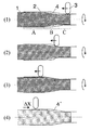
図1は、本発明に係る異形管の製造方法における成形プロセスの一例を示す図である。図1(1)において、成形型1は、金属管のワーク2(素管)に挿入されており、ともに軸周りに回転している。成形型1は、後述するが、図2に示すように、断面が円形の素管の内面とほぼ同じ断面形状aを有する柱体部分Aと、所望する異形管の内面とほぼ同じ断面形状cを有する柱体部分Cと、断面形状b1、b2が連続的に変化してA−Cの間を接続する錘台部分Bからなる。
FIG. 1 is a diagram showing an example of a forming process in the method for manufacturing a deformed pipe according to the present invention. In FIG. 1 (1), the forming die 1 is inserted into a work 2 (base tube) of a metal tube, and both rotate around an axis. As will be described later, as shown in FIG. 2, the
ワーク2は、図1(1)では成形途中の形状を表し、図中左側の素管のままの部分、右側の異形断面に成形済みの部分、及びそれらの中間の部分からなる。
The
加工ローラ3をワーク2の外周から半径方向に押し付けながら、軸方向に図1(1)〜(3)にそれぞれ示すように、図1中で左方向に移動し、成形型1とワーク2の間の空隙4を潰してワーク2の内面を成形型1に密着させる。
While pressing the
次いで図1(4)に示すように、加工ローラ3をワーク2から離し、成形型1に対してワーク2をΔXだけ軸方向に相対的に移動し、成形型1とワーク2の間に再び空隙4’を設ける。ここで図(1)に示す状態に戻って再度、図1(1)〜(4)に示す過程を繰り返せば、異形断面に成形済みの部分の長さがΔXずつ増加し、ワーク2を成形型1のCの部分に沿うような異形断面形状に成形できる。
Next, as shown in FIG. 1 (4), the
なお、ここでは加工ローラ3をCからAに向かって送りながら成形を行ったが、逆にAからCに向かって送りながら成形を行っても良いし、また加工ローラ3を両方向に往復させて成形を行っても良い。
Here, the forming was performed while feeding the
また図1では、加工ローラ3を1個だけしか図示していないが、複数の加工ローラを用いて成形を行った方がワークが安定し、加工時間も短縮できる。さらに図1(4)では成形型1を軸方向に関して固定し、ワーク2を軸方向に移動しているが、逆にワーク2を固定して成形型1を移動することによってそれらの間に空隙を設けても構わない。
Further, in FIG. 1, only one
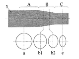
図2は、楕円断面管を製造するための成形型1の形状を例示する。成形型1の柱体部分Aは、素管の内面とほぼ同じ円形の断面形状aを有する。また柱体部分Cは、所望する異形管の内面とほぼ同じ楕円形の断面形状cを有する。途中の錘台部分Bでは、断面形状は円形aから、例えばb1、b2のような中間の形状を経て、楕円形cまで連続的に変化する。
FIG. 2 illustrates the shape of the
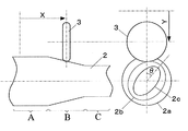
図3は、ワーク2と加工ローラ3の接触状態を示す図である。ワーク2の素管部分Aの断面形状は円形2aであり、成形済み部分Cの断面形状は楕円形2cである。ワーク2と加工ローラ3の接触点における断面2bにおいて、加工ローラ3がワーク2の内面を成形型(図示せず)に密着させるようにワーク2を加圧するには、加工ローラ3の半径方向変位Yをワーク2及び成形型の回転角θに同期して変化させればよい。
FIG. 3 is a diagram illustrating a contact state between the
また、接触点における断面形状2bは加工ローラ3の軸方向変位Xによって決定されるから、結局、加工ローラ3の半径方向変位Yは、ワーク2及び成形型の回転角θ及び加工ローラ3の軸方向変位Xの関数Y(θ,X)として表される。具体的にはY(θ,X)を制御を行う計算機上で数値の表として記憶しておき、θ及びXの数値に基づいて補間計算などによりYを求めればよい。
In addition, since the
また、図4は加工ローラ3の力制御による成形を示す。加工ローラ3の半径方向送りの駆動にリニアモータや油圧シリンダなどのアクチュエータ(図示せず)を用いれば、加工ローラ3の押し付け力Fを制御し、例えば押し付け力Fを一定値に保つことができる。
FIG. 4 shows molding by force control of the
そうすれば、成形型1とワーク2の回転にしたがって、成形型1の断面形状に加工ローラ3が倣って半径方向に前進または後退し、ワーク2の内面を成形型1に密着させることができる。この場合は加工ローラ3の半径方向変位のデータを計算機に与える必要がなくなり、簡便な制御方法で成形が可能である。
Then, as the
図5は、本発明の方法により異形管を製造するための装置の構成例を示す概略平面図である。成形型1はチャック5に把持され、主軸モータ6によって金属管のワーク2とともに軸周りに回転する。加工ローラ3は直動テーブル7によってワーク2を半径方向に加圧しながら、直動テーブル8によって軸方向に移動して、所望する異形管断面形状への縮径を行う。
FIG. 5 is a schematic plan view showing a configuration example of an apparatus for manufacturing a deformed pipe by the method of the present invention. The forming
ワーク2の端部は、チャック9で軸受10に固定され、加工ローラ3による部分成形が完了する毎に、直動テーブル11により成形型1に対してワーク2を軸方向に相対的に移動して、成形型1とワーク2の間に新たに縮径すべき空隙を設ける。
The end portion of the
以上、本発明に係る異形管の製造方法を実施するための最良の形態を実施例に基づいて説明したが、本発明は、このような実施例に限定されることなく、特許請求の範囲記載の技術的事項の範囲内で、いろいろな実施例があることは言うまでもない。 The best mode for carrying out the method for manufacturing a deformed pipe according to the present invention has been described based on the embodiments. However, the present invention is not limited to such embodiments, and the claims are described. It goes without saying that there are various embodiments within the scope of the technical matters.
本発明は、以上のような構成であるから、機械部品、化学プラント、その他各種の工業分野の異形管の製造に適用できる。 Since the present invention has the above-described configuration, it can be applied to manufacture of deformed pipes in machine parts, chemical plants, and other various industrial fields.
1 成形型
2 ワーク
3 加工ローラ
4、4’ 空隙
5 チャック
6 主軸モータ
7、8、11 直動テーブル
9 チャック
10 軸受
11 直動テーブル
DESCRIPTION OF
Claims (3)
前記素管の内面とほぼ同じ断面形状を有する柱体と、前記異形管の内面とほぼ同じ断面形状を有する柱体と、断面形状が連続的に変化して前記2つの柱体の間を接続する錘台からなる形状の成形型を前記素管に挿入し、
前記成形型と前記素管をともに軸周りに回転させつつ、前記素管の外周より加工ローラを半径方向に押し付けながら前記加工ローラを軸方向に移動して前記素管の内面を前記成形型に密着させる第一の工程と、
前記成形型に対して前記素管を軸方向に相対的に移動して前記成形型と前記素管の間に空隙を設ける第二の工程を順次繰り返し、
前記素管を所望の異形断面形状まで縮径することを特徴とする異形管の製造方法。 A method of manufacturing a metal pipe having an odd-shaped cross section such as an ellipse or a polygon from a metal pipe having a circular cross section,
A column having substantially the same cross-sectional shape as the inner surface of the blank tube, a column having substantially the same cross-sectional shape as the inner surface of the deformed tube, and a connection between the two columns by continuously changing the cross-sectional shape. Insert a mold having a frustum shape into the base tube,
While rotating both the forming die and the raw tube around the axis, the processing roller is moved in the axial direction while pressing the processing roller in the radial direction from the outer periphery of the raw tube so that the inner surface of the raw tube becomes the forming die. A first step of adhering;
The second step of sequentially moving the element pipe relative to the mold in the axial direction to provide a gap between the mold and the element pipe is sequentially repeated.
A method of manufacturing a deformed tube, comprising reducing the diameter of the raw tube to a desired deformed cross-sectional shape.
Priority Applications (1)
| Application Number | Priority Date | Filing Date | Title |
|---|---|---|---|
| JP2006039350A JP4635256B2 (en) | 2006-02-16 | 2006-02-16 | Manufacturing method of deformed pipe |
Applications Claiming Priority (1)
| Application Number | Priority Date | Filing Date | Title |
|---|---|---|---|
| JP2006039350A JP4635256B2 (en) | 2006-02-16 | 2006-02-16 | Manufacturing method of deformed pipe |
Publications (2)
| Publication Number | Publication Date |
|---|---|
| JP2007216258A JP2007216258A (en) | 2007-08-30 |
| JP4635256B2 true JP4635256B2 (en) | 2011-02-23 |
Family
ID=38494059
Family Applications (1)
| Application Number | Title | Priority Date | Filing Date |
|---|---|---|---|
| JP2006039350A Expired - Fee Related JP4635256B2 (en) | 2006-02-16 | 2006-02-16 | Manufacturing method of deformed pipe |
Country Status (1)
| Country | Link |
|---|---|
| JP (1) | JP4635256B2 (en) |
Families Citing this family (6)
| Publication number | Priority date | Publication date | Assignee | Title |
|---|---|---|---|---|
| EP2404684B1 (en) | 2009-03-04 | 2013-10-16 | Nippon Steel & Sumitomo Metal Corporation | Machining apparatus and machining method for metal plate |
| CN104998963A (en) * | 2015-07-09 | 2015-10-28 | 阜阳三环管桩有限公司 | Sheet iron pipe package structure |
| CN112642914A (en) * | 2020-12-21 | 2021-04-13 | 秦皇岛通桥科技有限公司 | Reducing-hot spinning forming method of stepped pipe blank for large-size expansion-compression formed automobile axle housing |
| CN113600644B (en) * | 2021-10-09 | 2021-12-07 | 启东锦桥轴承有限公司 | Spinning device for blank bar for bearing production |
| WO2025019974A1 (en) * | 2023-07-21 | 2025-01-30 | 中材科技(九江)有限公司 | Spinning roller bottom-closing machine |
| CN118371612B (en) * | 2024-06-20 | 2024-08-30 | 太原科技大学 | Thick-wall metal gas cylinder single-ring roller necking spinning machine and spinning method |
Family Cites Families (5)
| Publication number | Priority date | Publication date | Assignee | Title |
|---|---|---|---|---|
| GB1361437A (en) * | 1971-12-07 | 1974-07-24 | Yorkshire Imperial Metals Ltd | Method and apparatus for producing fluted tubes |
| JP3345225B2 (en) * | 1995-08-14 | 2002-11-18 | 株式会社神戸製鋼所 | Manufacturing method of deformed pipe |
| JP3769612B2 (en) * | 2001-12-13 | 2006-04-26 | 独立行政法人産業技術総合研究所 | Spinning method |
| JP2003326322A (en) * | 2002-05-15 | 2003-11-18 | Toyota Motor Corp | Method of manufacturing hollow member and catalytic converter having catalyst container formed of hollow member |
| US7584636B2 (en) * | 2003-12-08 | 2009-09-08 | National Institute Of Advanced Industrial Science And Technology | Metal spinning method and apparatus |
-
2006
- 2006-02-16 JP JP2006039350A patent/JP4635256B2/en not_active Expired - Fee Related
Also Published As
| Publication number | Publication date |
|---|---|
| JP2007216258A (en) | 2007-08-30 |
Similar Documents
| Publication | Publication Date | Title |
|---|---|---|
| KR20130099133A (en) | Spin forming process and apparatus for manufacturing articles by spin forming | |
| JP6803336B2 (en) | Ring rolling method and ring rolling equipment | |
| Wong et al. | Effects of roller path and geometry on the flow forming of solid cylindrical components | |
| JP5611526B2 (en) | Flexible forming equipment for forming 3D processed products | |
| JP2009279653A (en) | Method for bending pipe, rod, profiled section and similar blank, and corresponding device | |
| JP2007014983A (en) | Pipe forming method and pipe forming apparatus | |
| JP4635256B2 (en) | Manufacturing method of deformed pipe | |
| JP2005297041A (en) | Pipe forming method and pipe forming apparatus | |
| CN105328109B (en) | Large-scale dish axle integral piece local continuous loading forming method | |
| CN114260327A (en) | Method for preparing axial variable cross-section pipe by radial continuous extrusion | |
| JP2017087250A (en) | Method for manufacturing ring-shaped member | |
| JP6618940B2 (en) | Spinning method and cylindrical body having a head cone at the end | |
| WO2005056210A1 (en) | Method and device for spinning process | |
| JP2007203342A5 (en) | ||
| JP2009297787A (en) | Spinning method and apparatus | |
| CN102921847B (en) | A kind of precision rolling manufacturing process of cylindrical member and device | |
| JP4906849B2 (en) | Steel pipe expansion forming method and steel pipe expansion forming apparatus | |
| JP2011025283A (en) | Spinning method and device | |
| JP2007130673A (en) | Method of manufacturing outer race and inner race of bearing race using bearing steel pipe | |
| CN108080434B (en) | A processing method and stamping die for stepped deep hole shaft parts | |
| JP2010089103A (en) | Plastic working method of spline | |
| JP2005199338A (en) | CVJ inner race forging method, forging device and CVJ inner race | |
| JP4356644B2 (en) | Method for manufacturing hollow camshaft | |
| JP2013240828A (en) | Spinning method, spinning device, and shaped component | |
| JP2008238727A (en) | Method and apparatus for controlling parison deviation in a hollow molding machine |
Legal Events
| Date | Code | Title | Description |
|---|---|---|---|
| A621 | Written request for application examination |
Free format text: JAPANESE INTERMEDIATE CODE: A621 Effective date: 20080905 |
|
| A977 | Report on retrieval |
Free format text: JAPANESE INTERMEDIATE CODE: A971007 Effective date: 20101021 |
|
| TRDD | Decision of grant or rejection written | ||
| A01 | Written decision to grant a patent or to grant a registration (utility model) |
Free format text: JAPANESE INTERMEDIATE CODE: A01 Effective date: 20101102 |
|
| A01 | Written decision to grant a patent or to grant a registration (utility model) |
Free format text: JAPANESE INTERMEDIATE CODE: A01 |
|
| A61 | First payment of annual fees (during grant procedure) |
Free format text: JAPANESE INTERMEDIATE CODE: A61 Effective date: 20101104 |
|
| FPAY | Renewal fee payment (event date is renewal date of database) |
Free format text: PAYMENT UNTIL: 20131203 Year of fee payment: 3 |
|
| R150 | Certificate of patent or registration of utility model |
Ref document number: 4635256 Country of ref document: JP Free format text: JAPANESE INTERMEDIATE CODE: R150 Free format text: JAPANESE INTERMEDIATE CODE: R150 |
|
| FPAY | Renewal fee payment (event date is renewal date of database) |
Free format text: PAYMENT UNTIL: 20131203 Year of fee payment: 3 |
|
| R250 | Receipt of annual fees |
Free format text: JAPANESE INTERMEDIATE CODE: R250 |
|
| R250 | Receipt of annual fees |
Free format text: JAPANESE INTERMEDIATE CODE: R250 |
|
| S533 | Written request for registration of change of name |
Free format text: JAPANESE INTERMEDIATE CODE: R313533 |
|
| R350 | Written notification of registration of transfer |
Free format text: JAPANESE INTERMEDIATE CODE: R350 |
|
| R250 | Receipt of annual fees |
Free format text: JAPANESE INTERMEDIATE CODE: R250 |
|
| R250 | Receipt of annual fees |
Free format text: JAPANESE INTERMEDIATE CODE: R250 |
|
| R250 | Receipt of annual fees |
Free format text: JAPANESE INTERMEDIATE CODE: R250 |
|
| R250 | Receipt of annual fees |
Free format text: JAPANESE INTERMEDIATE CODE: R250 |
|
| R250 | Receipt of annual fees |
Free format text: JAPANESE INTERMEDIATE CODE: R250 |
|
| LAPS | Cancellation because of no payment of annual fees |